JP5177255B2 - Dark current interruption device and dark current interruption method - Google Patents
Dark current interruption device and dark current interruption method Download PDFInfo
- Publication number
- JP5177255B2 JP5177255B2 JP2011106824A JP2011106824A JP5177255B2 JP 5177255 B2 JP5177255 B2 JP 5177255B2 JP 2011106824 A JP2011106824 A JP 2011106824A JP 2011106824 A JP2011106824 A JP 2011106824A JP 5177255 B2 JP5177255 B2 JP 5177255B2
- Authority
- JP
- Japan
- Prior art keywords
- recording
- load
- failure
- dark current
- open
- Prior art date
- Legal status (The legal status is an assumption and is not a legal conclusion. Google has not performed a legal analysis and makes no representation as to the accuracy of the status listed.)
- Active
Links
Images


Classifications
-
- B—PERFORMING OPERATIONS; TRANSPORTING
- B60—VEHICLES IN GENERAL
- B60R—VEHICLES, VEHICLE FITTINGS, OR VEHICLE PARTS, NOT OTHERWISE PROVIDED FOR
- B60R16/00—Electric or fluid circuits specially adapted for vehicles and not otherwise provided for; Arrangement of elements of electric or fluid circuits specially adapted for vehicles and not otherwise provided for
- B60R16/02—Electric or fluid circuits specially adapted for vehicles and not otherwise provided for; Arrangement of elements of electric or fluid circuits specially adapted for vehicles and not otherwise provided for electric constitutive elements
- B60R16/03—Electric or fluid circuits specially adapted for vehicles and not otherwise provided for; Arrangement of elements of electric or fluid circuits specially adapted for vehicles and not otherwise provided for electric constitutive elements for supply of electrical power to vehicle subsystems or for
- B60R16/033—Electric or fluid circuits specially adapted for vehicles and not otherwise provided for; Arrangement of elements of electric or fluid circuits specially adapted for vehicles and not otherwise provided for electric constitutive elements for supply of electrical power to vehicle subsystems or for characterised by the use of electrical cells or batteries
Description
本発明は、暗電流遮断装置及び暗電流遮断方法に関する。 The present invention relates to a dark current interruption device and a dark current interruption method.
近年、車両では電装品が増加の傾向にあり、車両の輸送中や保管中において暗電流が増加する傾向にある。このため、車両の輸送中や保管中にバッテリが上がり易くなってしまう。そこで、車両の輸送中や保管中にバッテリが上がってしまうことを防止するため、負荷とバッテリとの間に設けられたヒューズのショートピン等を抜いておく技術が提案されている(例えば特許文献1,2参照)。また、負荷とバッテリとの間にリレーを設け、このリレーを開放するものが提案されている(例えば特許文献3参照)。 In recent years, electrical equipment tends to increase in vehicles, and dark current tends to increase during transportation and storage of vehicles. For this reason, the battery is likely to rise during transportation or storage of the vehicle. Therefore, in order to prevent the battery from going up during transportation or storage of the vehicle, a technique has been proposed in which a short pin of a fuse provided between the load and the battery is removed (for example, patent document). 1 and 2). Further, there has been proposed a relay that is provided between a load and a battery and the relay is opened (see, for example, Patent Document 3).
ここで、負荷には、故障記録を行うものが存在する。すなわち、負荷には、電力供給が行われず正常に作動できない場合、故障と判断してその旨を記録するものがある。しかし、従来装置では、暗電流を遮断するためにショートピン等を抜いた場合、故障記録を行う機能を有する負荷については電力供給が遮断されたことにより故障記録を行ってしまう。このように故障記録が行われてしまうと、ディーラ等では車両の販売時に故障記録を消去する作業が必要となってしまう。一方、故障記録されないようにショートピン等を抜かないとなると、暗電流を遮断できず、暗電流の遮断効果が低減されてしまう。 Here, some loads perform failure recording. In other words, when there is no power supply and normal operation cannot be performed, there is a load that determines that a failure has occurred and records that fact. However, in the conventional apparatus, when a short pin or the like is removed in order to cut off the dark current, the fault recording is performed because the power supply is cut off for the load having the function of performing the fault recording. If the failure record is performed in this way, a dealer or the like needs to delete the failure record when the vehicle is sold. On the other hand, if the short pin or the like is not removed so as not to record the failure, the dark current cannot be cut off, and the dark current cut-off effect is reduced.
本発明はこのような従来の課題を解決するためになされたものであり、その目的とするところは、故障記録の消去作業を不要とし、且つ、暗電流の遮断効果について向上を図ることが可能な暗電流遮断装置及び暗電流遮断方法を提供することにある。 The present invention has been made in order to solve such a conventional problem, and an object of the present invention is to eliminate the failure record erasing operation and improve the dark current interruption effect. An object of the present invention is to provide a dark current interruption device and a dark current interruption method.
本発明の暗電流遮断装置において故障記録手段は、負荷が作動しない場合に負荷の故障と判断して記録する。また、開閉判断手段は、バッテリと負荷との間に設けられて開放時に負荷への電力供給を遮断すると共に閉鎖時に負荷へ電力を供給させる開閉手段が開放されていることを判断する。記録禁止手段は、開閉手段が開放されていると判断された場合に、故障記録手段により故障と判断されて記録されることを禁止する。 In the dark current interrupting device of the present invention, the failure recording means records and records a load failure when the load does not operate. The open / close determining means determines that the open / close means provided between the battery and the load for cutting off power supply to the load when opened and supplying power to the load when closed is open. The recording prohibiting means prohibits recording when the failure recording means determines that there is a failure when it is determined that the opening / closing means is open.
また、本発明の暗電流遮断装置において故障記録手段は、負荷が作動しない場合に負荷の故障と判断して記録する。また、開閉判断手段は、バッテリと負荷との間に設けられて開放時に負荷への電力供給を遮断すると共に閉鎖時に負荷へ電力を供給させる開閉手段が開放されていることを判断する。記録禁止手段は、開閉手段が開放されていると判断された場合に、バッテリからの電力を開閉手段を介さない別経路により負荷に供給して、故障記録手段により故障と判断されて記録されないようにする。 Further, in the dark current interrupting device of the present invention, the failure recording means records and records a load failure when the load does not operate. The open / close determining means determines that the open / close means provided between the battery and the load for cutting off power supply to the load when opened and supplying power to the load when closed is open. When it is determined that the opening / closing means is open, the recording prohibiting means supplies power from the battery to the load through another path not via the opening / closing means so that the failure recording means determines that a failure has occurred and is not recorded. To.
本発明によれば、開閉手段が開放されていると判断された場合に、故障記録手段により
故障と判断されて記録されることを禁止するため、故障記録を行う負荷への電力供給を遮断していたとしても故障記録されることがなく、車両の販売時に故障記録を消去する作業が必要とならない。これにより、故障記録が行われる負荷についても暗電流を遮断することができる。従って、故障記録の消去作業を不要とし、且つ、暗電流の遮断効果について向上を図ることができる。
According to the present invention, when it is determined that the opening / closing means is open, it is determined that the failure recording means determines that a failure has occurred. Even if it is, the failure record is not recorded, and it is not necessary to delete the failure record when the vehicle is sold. As a result, dark current can be cut off even for a load for which failure recording is performed. Therefore, it is possible to eliminate the failure record erasing operation and improve the dark current interruption effect.
また、本発明によれば、開閉手段が開放されていると判断された場合に、バッテリからの電力を開閉手段を介さない別経路により負荷に供給して、故障記録手段により故障と判断されて記録されないようにする。このため、ショートピン等を抜いたとしても故障記録が行われる負荷については電力が供給され続けることとなり、故障記録が行われないこととなる。一方、故障記録が行われない負荷については電力供給路が遮断されて暗電流が遮断されることとなる。従って、故障記録の消去作業を不要とし、且つ、暗電流の遮断効果について向上を図ることができる。 Further, according to the present invention, when it is determined that the opening / closing means is open, the power from the battery is supplied to the load through another route not via the opening / closing means, and the failure recording means determines that a failure has occurred. Avoid recording. For this reason, even if the short pin or the like is removed, power is continuously supplied to the load for which failure recording is performed, and failure recording is not performed. On the other hand, for a load for which failure recording is not performed, the power supply path is cut off and the dark current is cut off. Therefore, it is possible to eliminate the failure record erasing operation and improve the dark current interruption effect.
以下、本発明の好適な実施形態を図面に基づいて説明する。図1は、本実施形態に係る暗電流遮断装置1の概略構成図である。図1に示すように、暗電流遮断装置1は、バッテリ10と、負荷20と、ヒューズブロック30と、マスターユニット40とから構成されている。
DESCRIPTION OF EXEMPLARY EMBODIMENTS Hereinafter, preferred embodiments of the invention will be described with reference to the drawings. FIG. 1 is a schematic configuration diagram of a dark
バッテリ10は、負荷20に対して電力供給を行うものである。負荷20は、メータ類など、車両に搭載される各種機器である。この負荷20には、車両輸送時や保管時において電力供給の必要が無いオーディオ機器等のものが多数ある。ヒューズブロック30は、定格以上の電流が流れた場合に大電流から負荷20を保護するヒューズ31を多数備えたものである。バッテリ10からの電流はこのヒューズブロック30を介して各負荷20に供給される。
The
また、ヒューズブロック30は、負荷20のうち一部の負荷20に対して電力供給を制限するためのカットオフスイッチ32を備えている。このカットオフスイッチ32は、バッテリ10と負荷20との間に設けられており、ショートピン32aを備えている。ショートピン32aは、引き抜き時(開放時)に負荷20への電力供給を遮断すると共に差し込み時(閉鎖時)に負荷20へ電力を供給させるものである。一般に車両の輸送時や保管時においては、ショートピン32aが引き抜かれており、バッテリ10からの電流が一部の負荷20に対して供給されないようになっている。これにより、車両の輸送時や保管時における暗電流が遮断されることとなる。
Further, the
しかし、負荷20には、故障記録を行うものが存在する。すなわち、負荷20には、電力供給が行われず正常に作動できない場合、故障と判断してその旨を記録するものがある。このため、ショートピン32aを引き抜いてしまうと、このような負荷20は故障記録を行ってしまう。故に、ディーラ等は、車両販売時に故障記録を消去しなければならなくなってしまう。一方、このような負荷20に対して輸送時や保管時においてもバッテリ10との接続関係を維持すると暗電流が流れてしまい、暗電流の遮断効果の低下につながっ
てしまう。そこで、本実施形態に係る暗電流遮断装置1は以下の構成を備えている。
However, some
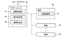
図2は、本実施形態に係る暗電流遮断装置1の要部を示すブロック図である。図2に示すように、マスターユニット40は、開閉判断部(開閉判断手段)41と、動作指示部(禁止指示手段)42と、記録禁止部(記録禁止手段)43とを備えている。また、負荷20は、上述した故障記録を行う故障記録部(故障記録手段)21を備えている。
FIG. 2 is a block diagram showing a main part of the dark
故障記録部21は、負荷20が作動しない場合に負荷20の故障と判断してその旨を記録するものである。開閉判断部41は、カットオフスイッチ32が開放されていること、すなわちショートピン32aが引き抜かれていることを判断するものである。図1に示すように、マスターユニット40はカットオフスイッチ32及び信号線33を介してバッテリ10と接続されており、開閉判断部41は信号線33から入力される電圧値に基づいて、カットオフスイッチ32が開放状態であるか閉鎖状態であるかを判断することができる。
The
記録禁止部43は、開閉判断部41によりカットオフスイッチ32が開放されていると判断された場合に、カットオフスイッチ32を介さない別経路Cにより、バッテリ10からの電力を、故障記録を行う負荷20に供給するものである。
When the open /
このような構成により、故障記録を行う負荷20であってもカットオフスイッチ32の開放時に故障記録されることなく、車両の販売時に故障記録を消去する作業が不要とすることができる。
With such a configuration, even if the
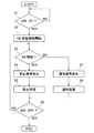
次に、フローチャートを参照して、本実施形態に係る暗電流遮断方法について説明する。図3は、本実施形態に係る暗電流遮断方法を示すフローチャートである。 Next, the dark current interruption method according to the present embodiment will be described with reference to a flowchart. FIG. 3 is a flowchart showing the dark current interruption method according to the present embodiment.
まず、図3に示すように、マスターユニット40は、イグニッションスイッチがオンされたか否かを判断する(S1)。イグニッションスイッチがオンされていないと判断した場合(S1:NO)、イグニッションスイッチがオンされたと判断されるまで、この処理は繰り返される。
First, as shown in FIG. 3, the
一方、イグニッションスイッチがオンされたと判断した場合(S1:YES)、開閉判断部41は、カットオフスイッチ32が開放状態であるか閉鎖状態であるかについて検出を開始する(S2)。以後、開閉判断部41は、イグニッションスイッチがオフされるまで、カットオフスイッチ32の状態を検出することとなる。
On the other hand, when it is determined that the ignition switch is turned on (S1: YES), the open /
その後、開閉判断部41は、カットオフスイッチ32が開放状態であるか否かを判断する(S3)。カットオフスイッチ32が開放状態であると判断した場合(S3:YES)、動作指示部42は、故障記録の禁止を指示する禁止信号を発生させる(S4)。そして、記録禁止部43は、故障記録を禁止する禁止処理を実行する(S5)。すなわち、記録禁止部43は、別経路Cにより故障記録を行う負荷20に対して電力を供給する。これにより、たとえショートピン32aを抜いていたとしても、故障記録を行う負荷20に対して電力が供給されて故障記録されないこととなる。また、故障記録を行わない負荷20には電力の供給経路が遮断されているため、暗電流についても遮断されることとなる。
Thereafter, the open / close determining
次いで、マスターユニット40は、イグニッションスイッチがオフされたか否かを判断する(S6)。イグニッションスイッチがオフされていないと判断した場合(S6:NO)、処理はステップS3に移行する。一方、イグニッションスイッチがオフされたと判断した場合(S6:YES)、図3に示す処理は終了する。
Next, the
また、カットオフスイッチ32が開放状態でないと判断した場合(S3:NO)、動作指示部42は、故障記録を禁止しない通常動作を指示する通常信号を発生させる(S7)。その後、記録禁止部43は故障記録を禁止する禁止処理を実行せず、通常処理を実行する(S8)。これにより、ユーザによる車両使用時において負荷20に故障があって電力供給が断たれた場合、故障記録部21により故障が記録されることとなり、ディーラ等における修理時に故障記録から故障している負荷20を容易に特定することができる。その後、処理は上記したステップS6に移行する。
If it is determined that the
このようにして、本実施形態に係る暗電流遮断装置1及び暗電流遮断方法によれば、カットオフスイッチ32が開放されていると判断された場合に、バッテリ10からの電力をカットオフスイッチ32を介さない別経路Cにより負荷20に供給して、故障記録部21により故障と判断されて記録されないようにする。このため、ショートピン32aを抜いたとしても故障記録が行われる負荷20については電力が供給され続けることとなり、故障記録が行われないこととなる。一方、故障記録が行われない負荷については電力供給路が遮断されて暗電流が遮断されることとなる。従って、故障記録の消去作業を不要とし、且つ、暗電流の遮断効果について向上を図ることができる。
Thus, according to the dark current interrupting
また、ショートピン32aを抜き差しすることにより、負荷20への電力供給を遮断したり、負荷20へ電力供給したりするカットオフスイッチ32を備える。ここで、本実施形態によらず暗電流を遮断する手法として、例えば故障記録を行う負荷20と故障記録を行わない負荷20とを分けておき、故障記録を行う負荷20と故障記録を行わない負荷20とのそれぞれにカットオフスイッチ32を設けることも考えられる。そして、故障記録を行わない負荷20のヒューズブロック32についてショートピン32aを抜くことが考えられる。しかし、この場合、作業者がショートピン32aを抜くべきカットオフスイッチ32を判断しなければならず、ショートピン32aを抜く作業において誤りが発生する可能性がある。これに対して、本実施形態ではたとえカットオフスイッチ32を備えていたとしても、作業者がショートピン32aを抜くべきカットオフスイッチ32を判断する必要がなく、カットオフスイッチ32のような手作業にて電力供給路を遮断するものを備えていたとしても適切に暗電流を遮断することができる。
In addition, a cut-
次に、本発明の第2実施形態を説明する。第2実施形態に係る暗電流遮断装置及び暗電流遮断方法は、第1実施形態のものと同様であるが、構成及び処理方法が一部異なっている。以下、第1実施形態との相違点について説明する。 Next, a second embodiment of the present invention will be described. The dark current interrupting device and the dark current interrupting method according to the second embodiment are the same as those of the first embodiment, but the configuration and the processing method are partially different. Hereinafter, differences from the first embodiment will be described.
図4は、第2実施形態に係る暗電流遮断装置1の要部を示すブロック図である。図4に示す暗電流遮断装置2は、第1実施形態のようにカットオフスイッチ32の開放時に故障記録を行う負荷20に対して電力を供給するのではなく、故障記録を行う負荷20に対して故障記録を行う機能を禁止させることとしている。
FIG. 4 is a block diagram showing a main part of the dark current interrupting
具体的に第2実施形態において、動作指示部42は、開閉判断部41によりカットオフスイッチ32が開放されていると判断された場合、故障記録を禁止する旨の禁止信号を負荷20に送信する。また、負荷20は、記録禁止部(記録禁止手段)22を備えている。負荷20の記録禁止部22は、動作指示部42からの禁止信号を受信すると、故障記録部21により故障と判断されて記録されることを禁止することとなる。すなわち、記録禁止部22は、故障記録部21による故障記録の機能をマスクすることとなる。
Specifically, in the second embodiment, when the open /
さらに、第2実施形態においてマスターユニット40は、記録禁止部43に代えて異常検出部(異常検出手段)44を備えている。異常検出部44は、異常検出部43はカットオフスッチ32の異常を検出するものである。この異常検出部43についての詳細は後述する。
Furthermore, in the second embodiment, the
また、記録禁止部22は、異常検出部43によりカットオフスッチ32の異常が検出された場合、故障記録を禁止する動作を実行しない。このため、カットオフスイッチ32の異常をカットオフスイッチ32の開放と誤って判断して、本来故障記録を行わなければならない場合に故障記録を禁止してしまうことなく、正常に記録処理を実行することができる。
In addition, when the
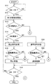
次に、フローチャートを参照して、第2実施形態に係る暗電流遮断方法について説明する。図5及び図6は、本実施形態に係る暗電流遮断方法を示すフローチャートである。なお、図5に示すステップS11,S12の処理は図3に示したステップS1,S2と同様であるため、説明を省略する。 Next, a dark current interruption method according to the second embodiment will be described with reference to a flowchart. 5 and 6 are flowcharts showing the dark current interruption method according to this embodiment. Note that the processing in steps S11 and S12 shown in FIG. 5 is the same as that in steps S1 and S2 shown in FIG.
ステップS13において異常判断部43は、カットオフスイッチ32に異常が発生していないか否かを判断する(S13)。カットオフスイッチ32の異常の判断方法について一例を説明する。まず、本実施形態では上記したように、カットオフスイッチ32の開放時に故障記録が禁止(マスク)される。このため、例えば、負荷20に故障が無ければ、カットオフスイッチ32の開放時には故障記録がマスクされると共に、カットオフスイッチ32の閉鎖時には通常の通りの判断が実行されて故障記録されることがない。また、負荷20の1つだけに故障記録されている場合、通常通りの判断が実行されてその負荷20に故障記録がされる。しかし、多数の負荷20に故障記録がされている場合は、多数の負荷20それぞれの故障とは考え難く、カットオフスイッチ32に異常が発生している判断することが妥当といえる。このため、異常判断部43は、このような多数の故障記録がされている場合に、カットオフスイッチ32の異常であると判断する。
In step S13, the
カットオフスイッチ32に異常が発生していないと判断した場合(S13:YES)、開閉判断部41は、カットオフスイッチ32が開放状態であるか否かを判断する(S14)。カットオフスイッチ32が開放状態であると判断した場合(S14:YES)、動作指示部42は、故障記録の禁止を指示する禁止信号を送信する(S15)。このとき、動作指示部42は、故障記録を行う機能を有する負荷20を選別して禁止信号を送信する。
When it is determined that no abnormality has occurred in the cut-off switch 32 (S13: YES), the open /
その後、マスターユニット40は、通信異常がないか否かを判断する(S16)。通信異常が発生していると、ステップS5において送信した禁止信号が負荷20に受信されず、故障記録がマスクされないためである。なお、本実施形態において負荷20は、動作指示部42からの信号を受信すると、受信した旨の信号をマスターユニット40に返信する。よって、マスターユニット40は、負荷20から返信があった場合に通信異常がないと判断し、負荷20からの返信がなかった場合に通信異常が発生していると判断する。
Thereafter, the
通信異常がなかった場合(S16:YES)、記録禁止部22は、故障記録を禁止する禁止処理を実行する(S17)。これにより、故障記録を行う負荷20であっても、電力が供給されていないときに故障記録がされることなく、ショートピン32aを抜いておくことにより暗電流を遮断することができる。
When there is no communication abnormality (S16: YES), the
次いで、マスターユニット40は、イグニッションスイッチがオフされたか否かを判断する(S18)。イグニッションスイッチがオフされていないと判断した場合(S18:NO)、処理はステップS13に移行する。一方、イグニッションスイッチがオフされたと判断した場合(S18:YES)、図5及び図6に示す処理は終了する。
Next, the
また、カットオフスイッチ32が開放状態でないと判断した場合(S14:NO)、動作指示部42は、故障記録を禁止しない通常動作を指示する通常信号を送信する(S19)。その後、マスターユニット40は、通信異常がないか否かを判断する(S20)。通
信異常の判断方法はステップS16と同じである。
If it is determined that the
そして、通信異常がなかった場合(S20:YES)、記録禁止部22は故障記録を禁止する禁止処理を実行せず、負荷20は通常の処理を実行する(S21)。これにより、ユーザによる車両使用時において負荷20に故障があった場合、故障記録部21により故障が記録されることとなり、ディーラ等における修理時に故障記録から故障している負荷20を容易に特定することができる。その後、処理は上記したステップS18に移行する。
If there is no communication abnormality (S20: YES), the
ところで、カットオフスイッチ32の異常があった場合(S13:NO)、処理は図6のステップS22に移行する。そして、動作指示部42は、故障記録を禁止しない通常動作を指示する通常信号を送信する(S22)。これにより、記録禁止部22は故障記録を禁止する禁止処理を実行せず、負荷20は通常の処理を実行する(S23)。
Incidentally, when there is an abnormality in the cut-off switch 32 (S13: NO), the process proceeds to step S22 in FIG. Then, the
ここで、通常の処理を実行する理由は以下の通りである。カットオフスイッチ32に異常があった場合、負荷20には電力供給がされないこととなる。このため、通常処理実行時には負荷20は故障記録を行うこととなる。しかも、カットオフスイッチ32の異常であることから多数の負荷20に故障記録が行われる。これにより、ディーラ等では多数の故障記録から多数の負荷20の個別の故障ではなくカットオフスイッチ32の異常であると判断でき、カットオフスイッチ32の交換・修理等を行うことができる。
Here, the reason for executing the normal processing is as follows. If the cut-
その後、処理はステップS24に移行し、マスターユニット40は、イグニッションスイッチがオフされたか否かを判断する(S24)。イグニッションスイッチがオフされていないと判断した場合(S24:NO)、処理はステップS22に移行する。一方、イグニッションスイッチがオフされたと判断した場合(S24:YES)、図5及び図6に示す処理は終了する。
Thereafter, the process proceeds to step S24, and the
また、図5に示すステップS16及びステップS20において通信異常があったと判断した場合(S16,S20:NO)、処理は図6のステップS25に移行する。そして、負荷20は、カットオフスイッチ32の状態を示す信号を未受信であるか否かを判断する(S25)。すなわち、負荷20は、ステップS15に示す禁止信号又はステップS19に示す通常信号を、過去に1回でも受信したか否かを判断することとなる。
If it is determined in step S16 and step S20 shown in FIG. 5 that there is a communication abnormality (S16, S20: NO), the process proceeds to step S25 in FIG. Then, the
カットオフスイッチ32の状態を示す信号を未受信であると判断した場合(S25:YES)、処理はステップS22に移行する。一方、未受信でないと判断した場合(S25:NO)、故障記録部21は、通信異常が発生する前の負荷20の故障記録を確定状態として保持する(S26)。その後、マスターユニット40は、イグニッションスイッチがオフされたか否かを判断する(S27)。イグニッションスイッチがオフされていないと判断した場合(S27:NO)、処理はステップS26に移行する。一方、イグニッションスイッチがオフされたと判断した場合(S27:YES)、図5及び図6に示す処理は終了する。
If it is determined that a signal indicating the state of the cut-
このようにして、第2実施形態に係る暗電流遮断装置1及び暗電流遮断方法によれば、カットオフスイッチ32が開放されていると判断された場合に、故障記録部21により故障と判断されて記録されることを禁止するため、故障記録を行う負荷20への電力供給を遮断していたとしても故障記録されることがなく、車両の販売時に故障記録を消去する作業が必要とならない。これにより、故障記録が行われる負荷20についても暗電流を遮断することができ、暗電流の遮断効果について向上を図ることができる。
Thus, according to the dark current interrupting
また、記録禁止部22は、異常検出部43によりカットオフスイッチ32の異常が検出
された場合、故障記録の禁止動作を実行しない。このため、カットオフスイッチ32の異常をカットオフスイッチ32の開放と誤って判断して、本来故障記録を行わなければならない場合、故障記録を禁止してしまうことなく、正常に記録処理を実行することができる。
In addition, when the
また、禁止指示部42からの信号が記録禁止部22に到達しない場合、負荷20の故障に関する記録内容を確定状態として保持するため、通信異常に起因して故障記録が書き換えられることがなく、通信異常の解消時に故障記録を消去する等の作業が発生してしまうことを防止することができる。
In addition, when the signal from the
また、ショートピン32aを抜き差しすることにより、負荷20への電力供給を遮断したり、負荷20へ電力供給したりするカットオフスイッチ32を備えるため、第1実施形態と同様に、適切に暗電流を遮断することができる。
In addition, since the cut-
以上、実施形態に基づき本発明を説明したが、本発明は上記実施形態に限られるものでは無く、本発明の趣旨を逸脱しない範囲で、変更を加えてもよい。 As described above, the present invention has been described based on the embodiments, but the present invention is not limited to the above-described embodiments, and modifications may be made without departing from the spirit of the present invention.
例えば、上記実施形態においては、ステップS13におけるカットオフスイッチ32の異常検出や、ステップS16及びステップS20における通信異常検出について一例を示したが、これに限らず、公知の他の方法を採用してもよい。
For example, in the above-described embodiment, an example of the abnormality detection of the cut-
1…暗電流装置
10…バッテリ
20…負荷
21…故障記録部(故障記録手段)
22…記録禁止部(記録禁止手段)
30…ヒューズブロック
31…ヒューズ
32…カットオフスイッチ
32a…ショートピン
33…信号線
40…マスターユニット
41…開閉判断部(開閉判断手段)
42…動作指示部(禁止指示手段)
43…記録禁止部(記録禁止手段)
44…異常検出部(異常検出手段)
C…別経路
DESCRIPTION OF
22 ... Recording prohibition section (recording prohibition means)
DESCRIPTION OF
42. Operation instruction section (prohibition instruction means)
43. Recording prohibition section (recording prohibition means)
44. Abnormality detection unit (abnormality detection means)
C ... Alternative route
Claims (4)
前記バッテリと前記負荷との間に設けられて開放時に前記負荷への電力供給を遮断すると共に閉鎖時に前記負荷へ電力を供給させる開閉手段と、
前記負荷が作動しない場合に負荷の故障と判断して記録する故障記録手段と、
前記開閉手段が開放されていることを判断する開閉判断手段と、
前記開閉判断手段により前記開閉手段が開放されていると判断された場合に、前記故障記録手段により故障と判断されて記録されることを禁止する記録禁止手段と、
前記開閉手段の異常を検出する異常検出手段とを備え、
前記記録禁止手段は、前記異常検出手段により前記開閉手段の異常が検出された場合、前記禁止動作を実行しない
ことを特徴とする暗電流遮断装置。 A battery for supplying power to the load;
An opening / closing means provided between the battery and the load for shutting off power supply to the load when opened and supplying power to the load when closed;
Failure recording means for determining and recording a load failure when the load is not activated; and
Open / close determining means for determining that the open / close means is open; and
A recording prohibiting means for prohibiting the recording by the failure recording means from being determined as a failure when the opening / closing determining means determines that the opening / closing means is open;
An abnormality detecting means for detecting an abnormality of the opening and closing means,
The dark current interrupting device , wherein the recording prohibiting means does not execute the prohibiting operation when an abnormality of the opening / closing means is detected by the abnormality detecting means .
前記記録禁止手段は、前記負荷に搭載されて、前記禁止指示手段からの信号により、前記故障記録手段により故障と判断されて記録されることを禁止し、
前記故障記録手段は、前記前記禁止指示手段からの信号が前記記録禁止手段に到達しない場合、負荷の故障に関する記録内容を確定状態として保持する
ことを特徴とする請求項1に記載の暗電流遮断装置。 When the open / close determining means determines that the open / close means is open, the apparatus further comprises prohibition instruction means for transmitting a signal indicating that the failure recording process is prohibited,
The recording prohibition means is mounted on the load and prohibits recording by the failure recording means determined to be a failure by a signal from the prohibition instruction means,
2. The dark current interruption according to claim 1, wherein when the signal from the prohibition instruction unit does not reach the recording prohibition unit, the failure recording unit holds a recorded content related to a load failure as a finalized state. apparatus.
前記バッテリと前記負荷との間に設けられて開放時に前記負荷への電力供給を遮断すると共に閉鎖時に前記負荷へ電力を供給させる開閉手段と、を備えた暗電流遮断装置の暗電流遮断方法であって、
前記負荷が作動しない場合に負荷の故障と判断して記録する故障記録工程と、
前記開閉手段が開放されていることを判断する開閉判断工程と、
前記開閉判断工程において前記開閉手段が開放されていると判断された場合に、前記故障記録工程において故障と判断されて記録されることを禁止する記録禁止工程と、
前記開閉手段の異常を検出する異常検出工程とを含み、
前記記録禁止工程は、前記異常検出工程により前記開閉手段の異常が検出された場合、前記禁止動作を実行しない
ことを特徴とする暗電流遮断装置の暗電流遮断方法。 A battery for supplying power to the load;
A dark current interrupting method for a dark current interrupting device, comprising: an open / close means provided between the battery and the load for shutting off power supply to the load when opened and for supplying power to the load when closed; There,
A failure recording step of determining and recording a load failure when the load is not activated; and
An opening / closing determination step for determining that the opening / closing means is open;
A recording prohibiting step for prohibiting recording when it is determined that the failure is recorded in the failure recording step when it is determined that the opening / closing means is opened in the opening / closing determining step;
An abnormality detection step of detecting an abnormality of the opening and closing means,
The dark current interrupting method of the dark current interrupting device, wherein the recording prohibiting step does not execute the prohibiting operation when an abnormality of the opening / closing means is detected by the abnormality detecting step .
Priority Applications (5)
| Application Number | Priority Date | Filing Date | Title |
|---|---|---|---|
| JP2011106824A JP5177255B2 (en) | 2011-05-12 | 2011-05-12 | Dark current interruption device and dark current interruption method |
| PCT/JP2012/055042 WO2012153562A1 (en) | 2011-05-12 | 2012-02-29 | Dark current cutoff device and dark current cutoff method |
| CN201280022926.XA CN103517831B (en) | 2011-05-12 | 2012-02-29 | Dark current cutoff device and dark current cutting-off method |
| US14/116,936 US9484761B2 (en) | 2011-05-12 | 2012-02-29 | Dark current cutoff device and dark current cutoff method |
| EP12781782.3A EP2708421B1 (en) | 2011-05-12 | 2012-02-29 | Dark current cutoff device and dark current cutoff method |
Applications Claiming Priority (1)
| Application Number | Priority Date | Filing Date | Title |
|---|---|---|---|
| JP2011106824A JP5177255B2 (en) | 2011-05-12 | 2011-05-12 | Dark current interruption device and dark current interruption method |
Publications (3)
| Publication Number | Publication Date |
|---|---|
| JP2012236503A JP2012236503A (en) | 2012-12-06 |
| JP2012236503A5 JP2012236503A5 (en) | 2013-01-24 |
| JP5177255B2 true JP5177255B2 (en) | 2013-04-03 |
Family
ID=47139048
Family Applications (1)
| Application Number | Title | Priority Date | Filing Date |
|---|---|---|---|
| JP2011106824A Active JP5177255B2 (en) | 2011-05-12 | 2011-05-12 | Dark current interruption device and dark current interruption method |
Country Status (5)
| Country | Link |
|---|---|
| US (1) | US9484761B2 (en) |
| EP (1) | EP2708421B1 (en) |
| JP (1) | JP5177255B2 (en) |
| CN (1) | CN103517831B (en) |
| WO (1) | WO2012153562A1 (en) |
Cited By (1)
| Publication number | Priority date | Publication date | Assignee | Title |
|---|---|---|---|---|
| US11431179B2 (en) | 2017-05-30 | 2022-08-30 | Continental Automotive Gmbh | Input circuit capable of reducing dark current |
Families Citing this family (6)
| Publication number | Priority date | Publication date | Assignee | Title |
|---|---|---|---|---|
| JP5966962B2 (en) * | 2013-02-14 | 2016-08-10 | トヨタ自動車株式会社 | Hybrid vehicle travel control device |
| KR101714518B1 (en) * | 2015-09-11 | 2017-03-22 | 현대자동차주식회사 | Method and Apparutus for Preventing Excess of Dark Current In Telematics Terminal |
| JP2017121864A (en) * | 2016-01-07 | 2017-07-13 | 株式会社オートネットワーク技術研究所 | Power-feeding relay circuit, sub-battery module and power source system |
| KR101756008B1 (en) * | 2016-04-11 | 2017-07-10 | 현대자동차주식회사 | Control method and system of low voltage dc-dc converter for hybrid vehicle |
| KR102360155B1 (en) * | 2016-05-30 | 2022-02-09 | 현대자동차주식회사 | Apparatus for diagnosing icu and method thereof |
| CN109515350B (en) * | 2018-11-13 | 2021-09-24 | 深圳市路畅科技股份有限公司 | Protective circuit |
Family Cites Families (7)
| Publication number | Priority date | Publication date | Assignee | Title |
|---|---|---|---|---|
| JP3316791B2 (en) | 1996-08-28 | 2002-08-19 | 矢崎総業株式会社 | Vehicle battery power supply |
| JP2002235599A (en) * | 2001-02-09 | 2002-08-23 | Isuzu Motors Ltd | Trouble diagnosing device for cab-over type truck |
| DE10300464A1 (en) * | 2003-01-07 | 2004-07-15 | Intedis Gmbh & Co. Kg | Vehicle electrical system |
| JP4345589B2 (en) * | 2004-06-29 | 2009-10-14 | トヨタ自動車株式会社 | Disconnection detection device for vehicle and disconnection detection method for vehicle |
| JP2008126812A (en) * | 2006-11-20 | 2008-06-05 | Toyota Motor Corp | Vehicle height adjusting device |
| JP2008179221A (en) | 2007-01-24 | 2008-08-07 | Furukawa Electric Co Ltd:The | Power source feeding device for vehicle |
| JP4450037B2 (en) * | 2007-09-11 | 2010-04-14 | トヨタ自動車株式会社 | Failure information detection apparatus, failure information detection system, server, failure information detection method |
-
2011
- 2011-05-12 JP JP2011106824A patent/JP5177255B2/en active Active
-
2012
- 2012-02-29 EP EP12781782.3A patent/EP2708421B1/en active Active
- 2012-02-29 CN CN201280022926.XA patent/CN103517831B/en active Active
- 2012-02-29 WO PCT/JP2012/055042 patent/WO2012153562A1/en active Application Filing
- 2012-02-29 US US14/116,936 patent/US9484761B2/en active Active
Cited By (1)
| Publication number | Priority date | Publication date | Assignee | Title |
|---|---|---|---|---|
| US11431179B2 (en) | 2017-05-30 | 2022-08-30 | Continental Automotive Gmbh | Input circuit capable of reducing dark current |
Also Published As
| Publication number | Publication date |
|---|---|
| EP2708421A4 (en) | 2014-12-17 |
| EP2708421B1 (en) | 2019-02-13 |
| US9484761B2 (en) | 2016-11-01 |
| EP2708421A1 (en) | 2014-03-19 |
| CN103517831A (en) | 2014-01-15 |
| US20140077620A1 (en) | 2014-03-20 |
| WO2012153562A1 (en) | 2012-11-15 |
| CN103517831B (en) | 2016-01-20 |
| JP2012236503A (en) | 2012-12-06 |
Similar Documents
| Publication | Publication Date | Title |
|---|---|---|
| JP5177255B2 (en) | Dark current interruption device and dark current interruption method | |
| JP6398931B2 (en) | In-vehicle power supply device and control method thereof | |
| KR101273144B1 (en) | Over current relay for diagnosing open condition of current transformer secondary circuit and method thereof | |
| JP5871940B2 (en) | Electronic circuit breaker with alternative operation mode using auxiliary power supply | |
| JP6614452B2 (en) | Relay device | |
| KR101846345B1 (en) | reactor trip switchgear system | |
| JP2010036646A (en) | Power supplying device for vehicle and power supplying method for vehicle | |
| JP5167915B2 (en) | Auxiliary power supply system for electric power steering system | |
| JP2001309546A (en) | Protector for vehicle wiring system | |
| JP2013062974A (en) | Protection relay system | |
| EP2651026B1 (en) | Automatic fault isolation methodology | |
| JP4020203B2 (en) | Automatic monitoring circuit for protective relay device | |
| KR101151969B1 (en) | Apparatus and method for protecting power transmission line | |
| KR102036413B1 (en) | Logic of Breaker Failure(BF) Protective Element using Apparent Power Detective Element for Generator Circuit Breaker(GCB) in Power Plant | |
| JP2015177617A (en) | Protection relay | |
| JP2005312180A (en) | Digital protective relay system | |
| JP5401879B2 (en) | Ground fault sequence interrupting device | |
| KR101545891B1 (en) | Triple protecting apparatus using 3 relays | |
| JP3562674B2 (en) | Transformer protection relay | |
| JP2005168150A (en) | Automatic inspection device for protective relay device | |
| KR102572958B1 (en) | Protecting circuit and a method for protecting of circuit using the same | |
| JP4885594B2 (en) | Switch | |
| JP2009022063A (en) | Power transmission line protection system, and protection relay device | |
| KR101033125B1 (en) | A method for compensating brake out time error of relay protecting electric power system | |
| JP2022108553A (en) | On-vehicle power source device and on-vehicle power source control method |
Legal Events
| Date | Code | Title | Description |
|---|---|---|---|
| A521 | Request for written amendment filed |
Free format text: JAPANESE INTERMEDIATE CODE: A523 Effective date: 20121114 |
|
| A621 | Written request for application examination |
Free format text: JAPANESE INTERMEDIATE CODE: A621 Effective date: 20121114 |
|
| A871 | Explanation of circumstances concerning accelerated examination |
Free format text: JAPANESE INTERMEDIATE CODE: A871 Effective date: 20121114 |
|
| RD02 | Notification of acceptance of power of attorney |
Free format text: JAPANESE INTERMEDIATE CODE: A7422 Effective date: 20121114 |
|
| A975 | Report on accelerated examination |
Free format text: JAPANESE INTERMEDIATE CODE: A971005 Effective date: 20121130 |
|
| TRDD | Decision of grant or rejection written | ||
| A01 | Written decision to grant a patent or to grant a registration (utility model) |
Free format text: JAPANESE INTERMEDIATE CODE: A01 Effective date: 20121211 |
|
| A61 | First payment of annual fees (during grant procedure) |
Free format text: JAPANESE INTERMEDIATE CODE: A61 Effective date: 20121224 |
|
| R150 | Certificate of patent or registration of utility model |
Ref document number: 5177255 Country of ref document: JP Free format text: JAPANESE INTERMEDIATE CODE: R150 |