JP5171170B2 - Medical image diagnosis support system - Google Patents
Medical image diagnosis support system Download PDFInfo
- Publication number
- JP5171170B2 JP5171170B2 JP2007232560A JP2007232560A JP5171170B2 JP 5171170 B2 JP5171170 B2 JP 5171170B2 JP 2007232560 A JP2007232560 A JP 2007232560A JP 2007232560 A JP2007232560 A JP 2007232560A JP 5171170 B2 JP5171170 B2 JP 5171170B2
- Authority
- JP
- Japan
- Prior art keywords
- image
- shadow
- abnormal candidate
- medical image
- medical
- Prior art date
- Legal status (The legal status is an assumption and is not a legal conclusion. Google has not performed a legal analysis and makes no representation as to the accuracy of the status listed.)
- Expired - Fee Related
Links
- 238000003745 diagnosis Methods 0.000 title claims description 16
- 230000002159 abnormal effect Effects 0.000 claims description 40
- 238000006243 chemical reaction Methods 0.000 claims description 7
- 239000000203 mixture Substances 0.000 claims description 7
- 239000007787 solid Substances 0.000 claims description 4
- 239000005337 ground glass Substances 0.000 claims description 2
- 230000002093 peripheral effect Effects 0.000 claims description 2
- 230000002194 synthesizing effect Effects 0.000 claims 2
- 238000000034 method Methods 0.000 description 23
- 238000010586 diagram Methods 0.000 description 13
- 238000003384 imaging method Methods 0.000 description 4
- 206010028980 Neoplasm Diseases 0.000 description 3
- 201000011510 cancer Diseases 0.000 description 3
- 238000001514 detection method Methods 0.000 description 2
- 238000002601 radiography Methods 0.000 description 2
- 206010058467 Lung neoplasm malignant Diseases 0.000 description 1
- 238000004458 analytical method Methods 0.000 description 1
- 238000002059 diagnostic imaging Methods 0.000 description 1
- 239000004973 liquid crystal related substance Substances 0.000 description 1
- 210000004072 lung Anatomy 0.000 description 1
- 201000005202 lung cancer Diseases 0.000 description 1
- 208000020816 lung neoplasm Diseases 0.000 description 1
- 210000000056 organ Anatomy 0.000 description 1
- 238000003672 processing method Methods 0.000 description 1
- 238000011158 quantitative evaluation Methods 0.000 description 1
- 238000003325 tomography Methods 0.000 description 1
- 235000021419 vinegar Nutrition 0.000 description 1
- 239000000052 vinegar Substances 0.000 description 1
Images


Landscapes
- Apparatus For Radiation Diagnosis (AREA)
Description
本発明は、デジタルラジオグラフィを含むX線画像診断装置に表示される画像を用いて医師の診断を支援する医用画像診断支援システムに関する。 The present invention relates to a medical image diagnosis support system that supports a diagnosis of a doctor using an image displayed on an X-ray image diagnosis apparatus including digital radiography.
従来、医師が読影によって肺がん等の異常陰影を発見する場合、単純X線画像よりもCTなどの断層像の方が異常陰影の早期発見に優れていることは知られている。例えば、X線画像の場合では、約3cm程度の大きさの陰影でないと発見は困難であるが、CTなどの断層像の場合は、約5mm程度の大きさを発見することが可能である。そこで、医師は、まずCT画像を読影して異常陰影位置を確認したら、次回からは低被曝のX線画像を撮影する。そして、断層画像に基づいてCADや読影によって発見された異常陰影などを特定領域として、その座標を取得するものである。取得された特定領域の座標を、X線画像上の座標又は領域に変換し、変換後の座標又は領域を特定することができるように通常のX線画像上にマークを付けて表示する場合がある。(例えば、特許文献1)
しかしながら、特許文献1では、異常陰影の存在領域が明確になるに過ぎず、X線画像のみからは異常陰影を視認することが早期のがんなどの異常陰影が見つけられないという未解決の問題がある。 However, in Patent Document 1, the existence area of the abnormal shadow is only clarified, and it is an unresolved problem that the abnormal shadow such as early cancer cannot be found by viewing the abnormal shadow only from the X-ray image. There is.
本発明の目的は、早期のがんなどの異常陰影をX線画像上で容易に視認できるようにした医用画像診断支援システムを提供することにある。 An object of the present invention is to provide a medical image diagnosis support system that enables an abnormal shadow such as early cancer to be easily visually recognized on an X-ray image.
本発明の医用画像診断支援システムは、被検者の断層画像上で予め抽出された異常候補陰影領域の位置を取得する位置取得手段と、前記位置取得手段によって取得された異常候補陰影の位置を、前記被検者のX線画像上の座標又は領域に変換する位置変換手段と、前記位置変換手段によって変換された前記X線画像上の座標又は領域に前記異常候補陰影領域の画素情報を合成し、第1の画像を生成する画像合成手段と、前記画像合成手段によって生成された第1の画像を表示する表示手段と、を備える。 The medical image diagnosis support system according to the present invention includes a position acquisition unit that acquires a position of an abnormal candidate shadow region extracted in advance on a tomographic image of a subject, and a position of the abnormal candidate shadow acquired by the position acquisition unit. A position conversion means for converting the coordinates or area on the X-ray image of the subject and the pixel information of the abnormal candidate shadow area to the coordinates or area on the X-ray image converted by the position conversion means. And an image composition means for generating the first image, and a display means for displaying the first image generated by the image composition means.
本発明によれば、早期のがんなどの異常陰影をX線画像上で視認可能とした医用画像診断支援システムを提供することができるという効果を奏する。 According to the present invention, it is possible to provide a medical image diagnosis support system in which abnormal shadows such as early cancer can be visually recognized on an X-ray image.
以下、添付図面に従って、本発明に係る医用画像診断支援システムの好ましい実施の形態について詳説する。 Hereinafter, preferred embodiments of a medical image diagnosis support system according to the present invention will be described in detail with reference to the accompanying drawings.
図1は、発明の一実施の形態に係る医用画像診断支援システム1の構成を示すハードウエア構成図である。 FIG. 1 is a hardware configuration diagram showing a configuration of a medical image diagnosis support system 1 according to an embodiment of the invention.
図1の医用画像診断支援システム1は、X線CT装置、MRI装置、超音波装置、PET、などの医用断層画像撮影装置2と、医用断層画像撮影装置2に撮影された医用画像を格納する画像データベース4と、医用画像を表示する医用画像表示装置10とを備える。医用断層画像撮影装置2、画像データベース4及び医用画像表示装置10は、LAN3等のネットワークにより相互に接続される。
The medical image diagnosis support system 1 in FIG. 1 stores a medical
医用画像表示装置10は、中央処理装置(CPU)11と、主メモリ12と、磁気ディスク13と、表示メモリ14と、キーボード16と、コントローラ18と、が共通バス19によって相互に接続される。
In the medical
CPU11は、主として各構成要素の動作を制御する。主メモリ12は、装置の制御プログラムが格納されたり、プログラム実行時の作業領域となったりする。磁気ディスク13は、オペレーティングシステム(OS)、周辺機器のデバイスドライブ、医用画像から注目部位を定量評価する処理等を行うためのプログラムを含む各種アプリケーションソフト等を格納する。表示メモリ14は、ディスプレイ15への表示に供する表示用データを一時記憶する。ディスプレイ15は、表示メモリ14ろ接続され、表示メモリ14からのデータに基づいて画像を表示するもので、CRTモニタや液晶モニタ等の種類がある。キーボード16は、被検者のIDなどの主に文字情報を入力する。マウス17は、コントローラ18に接続され、ディスプレイ15にマウス用カーソールが表示され、ディスプレイ15上に設けられるソフトスイッチや、表示画像の関心領域の設定などを入力する。コントローラ18は、マウス17の状態を検出してモニタ15上のマウスポインタの位置やマウス17の状態等の信号をCPU11に出力する。
The
本実施の形態においては、医用画像表示装置10は、LAN3を介して画像データベース4から医用画像を読み出すが、医用画像表示装置10に接続された記憶装置、例えばFDD、CD-RWドライブ、MOドライブ、ZIPドライブ等から医用画像を読み込んでも良い。また、LAN3を経由して、医用断層画像撮影装置2から直接医用画像を取得してもよい。
In the present embodiment, the medical
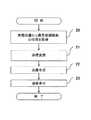
図2は、図1の医用画像診断支援装置が実行するメインフローを示す図である。図1のCPU11はこのメインフローに従って動作する。以下、このメインフローの詳細をステップ順に説明する。
FIG. 2 is a diagram showing a main flow executed by the medical image diagnosis support apparatus of FIG. The
まず、医用画像診断支援装置のディスプレイ14上に被検者のID入力画面が表示されるので、操作者は患者のID番号を入力する。すると、医用画像モダリティによって予め撮影された断層像の中から診断対象となる患者のID番号に対応した断層画像を磁気ディスク12から読み出される。読み出しが終了したら、断層画像(現在画像)を表示する。
First, since the subject ID input screen is displayed on the display 14 of the medical image diagnosis support apparatus, the operator inputs the patient ID number. Then, a tomographic image corresponding to the ID number of the patient to be diagnosed is read from the
図2は、医用画像表示装置の実行プログラムの一例を示すフローチャート図である。図3から図5は、図2の医用画像表示装置における画像表示の一例を示す図である。 FIG. 2 is a flowchart showing an example of an execution program of the medical image display apparatus. 3 to 5 are diagrams showing an example of image display in the medical image display apparatus of FIG.
[ステップS20]
CPU11は、CT画像などの断層画像上の異常陰影の座標を取得する。取得の手法は、マウスなどを使い操作者が手動入力によって抽出してもよく、また特開2002-325761号公報に開示されているようなCAD(Computer-Aided Detection)処理を用い、自動的に異常候補陰影の位置を抽出するようにしてもよい。
[Step S20]
The
[ステップS21]
CPU11は、ステップS20で取得された異常候補陰影の座標を、X線画像診断装置に撮影されたX線画像上の座標に変換する。CT装置とX線画像診断装置との間で変換式が決まっている場合は、その式を用いる。式が決まっていない場合は、例えば、まずCT画像から計算により擬似X線画像を生成し、X線画像診断装置に撮影されたX線画像と擬似X線画像全体の大きさや、臓器(例:肺など)の解剖学的な情報を形状などの類似性に基づいて位置合わせを計算することにより、座標変換式を求めてもよい。
[Step S21]
The
[ステップS22]
ステップS21では、CPU11がCT画像上の異常候補陰影が撮影X線画像上に対応する位置を求めた。CPU11は前記X線画像上の座標又は領域に前記異常候補陰影領域の画素情報を合成し、第1の画像を生成する。また、X線画像上の対応する部位を強調処理してもよい。この強調処理の方法は、その画素値のn倍でも良い。また、その近傍画素の最大値で強調しても良い。
[Step S22]
In step S21, the
[ステップS23]
CPU11は、ステップS22で生成された第1の画像を表示メモリ14に書き込む。表示メモリ14に書き込まれた第1の画像は、図3から図5に示すようにディスプレイ15に表示される。
[Step S23]
The
図3において、表示画像中の表示領域30には、並列でDR(デジタルラジオグラフィ)などで撮影されたX線画像31と、本発明の第1の画像32が並列表示されている。また、図4に示すように、単独で第1の画像32を表示してもよい。
In FIG. 3, an
また、図5では、同一被検者の過去に撮影した画像について第1の画像と同じ処置をした第2の画像と、当日撮影したX線画像33が表示されている。これにより、X線画像上での経過観察が容易に行うことが可能になる。
Further, in FIG. 5, a second image obtained by performing the same treatment as the first image on an image photographed in the past of the same subject and an
図6は、図2の別実施形態を示すフローチャート、図7は、図6の医用画像表示装置における画像表示の一例を示す図である。 FIG. 6 is a flowchart showing another embodiment of FIG. 2, and FIG. 7 is a diagram showing an example of image display in the medical image display apparatus of FIG.
[ステップS60]
CPU11は、ステップS20と同様、断層画像上の異常陰影の座標を取得する。
[Step S60]
As in step S20, the
[ステップS61]
CPU11は、断層画像上の異常陰影の座標を取得処理において、手動で位置を取得した場合、異常陰影候補の大きさや全体における位置などの特徴量を算出する。
[Step S61]
When the
[ステップS62]
CPU11は、ステップS21と同様、異常陰影候補の座標を、X線画像上の座標に変換する。
[Step S62]
As in step S21, the
[ステップS63]
CPU11は、異常陰影候補の特徴(大きさ、存在する位置や陰影タイプ)に応じた陰影強調方法により、X線画像上の陰影を強調する。ここで、陰影タイプとは、充実陰影、すりガラス状陰影や充実とすりガラス混合のように分類されるものである。
[Step S63]
The
[ステップS64]
CPU11は、ステップS63で異常候補陰影部分を強調したX線画像を表示メモリ14に書き込む。表示メモリ14に書き込まれた強調X線画像は、図7に示すようにディスプレイ15に表示される。
[Step S64]
The
図8は、医用画像表示装置の別の実行プログラムの一例を示すフローチャート、図9は、図8の医用画像表示装置における画像表示の一例を示す図である。 FIG. 8 is a flowchart showing an example of another execution program of the medical image display device, and FIG. 9 is a diagram showing an example of image display in the medical image display device of FIG.
[ステップS80]
CPU11は、ステップS20と同様、断層画像上の異常候補陰影の座標を取得する。
[Step S80]
As in step S20, the
[ステップS81]
CPU11は、ステップS21と同様、異常候補陰影の座標を、X線画像上の座標に変換する。
[Step S81]
As in step S21, the
[ステップS82]
CPU11は、ステップS22と同様、X線画像上の異常候補陰影部位を強調する。強調方法は前述の場合と同じである。
[Step S82]
As in step S22, the
[ステップS83]
CPU11は、同一被検者の過去に撮影したCT画像(過去画像)において、ステップS80で取得した異常候補陰影の座標と同部位を取得する。
[Step S83]
The
[ステップS84]
CPU11は、ステップS83で取得した過去画像における異常候補陰影部位を、領域解析処理を行う。
[Step S84]
The
[ステップS85]
CPU11は、ステップS81と同様、過去画像における異常候補陰影の座標を、X線画像上の座標に変換する。さらに、この変換画像を、当日撮影した画像と位置が合うように位置合わせ処理を行う。変換方法は前述の場合と同じである。
[Step S85]
Similar to step S81, the
[ステップS86]
CPU11は、ステップS82と同様、X線画像上の異常候補陰影部位を強調する。強調方法は前述の場合と同じである。
[Step S86]
As in step S82, the
[ステップS87]
CPU11は、ステップS82とステップS86で強調したX線画像を表示メモリ14に書き込む。表示メモリ14に書き込まれた強調X線画像は、図9に示すようにディスプレイ15に表示される。
[Step S87]
CPU11 writes the X-ray image that was highlighted in the scan STEP S82 and vinegar STEP S86 in the display memory 14. The emphasized X-ray image written in the display memory 14 is displayed on the
図10は図2及び図6の医用画像表示方法及び装置の処理の流れを模式的に示す図である。図10に示すように、CT画像のような断層画像の中からCAD処理叉は読影医によって異常候補陰影が検出された場合、この異常候補陰影が断層画像上の座標として取得される。CPU11はCT画像に基づいて補間処理と再構成処理によって、擬似X線画像を作成し、実際のX線画像と大きさ、傾きなどの全体の位置合わせ及び、体内のランドマーク(例:肋骨)の位置で位置合わせを行う。この位置合わせが終了したら、CPU11は、X線画像上の対応する異常候補陰影部位を強調処理し、表示する。これより、X線画像では捕らえることが困難な陰影を捉えることができることのほか、注目部位全体の形状などを把握できる。
FIG. 10 is a diagram schematically showing a processing flow of the medical image display method and apparatus shown in FIGS. As shown in FIG. 10, when an abnormal candidate shadow is detected from a tomographic image such as a CT image by a CAD process or an interpretation doctor, the abnormal candidate shadow is acquired as coordinates on the tomographic image. CPU11 creates a pseudo X-ray image by interpolation processing and reconstruction processing based on the CT image, aligns the actual X-ray image with the entire size, inclination, etc., and landmarks in the body (eg, ribs) Align at the position. When this alignment is completed, the
図11は医用画像表示方法及び装置における画像表示の一例である。読影医は本発明により要注意部位が明確になっているので、CT画像と並列表示することで容易に確認することが可能になる。 FIG. 11 shows an example of image display in the medical image display method and apparatus. Since the site requiring attention is clarified by the present invention, the image interpretation doctor can easily confirm by displaying in parallel with the CT image.
1 医用画像表示システム、2 医用断層画像撮影装置、3 LAN、4 画像データベース、10 医用画像表示装置、11 CPU、12 主メモリ、13 磁気ディスク、14 表示メモリ、15 モニタ、16 キーボード、17 マウス、18 コントローラ、19 共通バス 1 Medical image display system, 2 Medical tomography system, 3 LAN, 4 Image database, 10 Medical image display device, 11 CPU, 12 Main memory, 13 Magnetic disk, 14 Display memory, 15 Monitor, 16 Keyboard, 17 Mouse, 18 controller, 19 common bus
Claims (4)
前記位置取得手段によって取得された前記断層画像上での異常候補陰影領域の位置を、前記被検者のX線画像上の座標又は領域に変換する位置変換手段と、
前記位置変換手段によって変換された前記X線画像上の座標又は領域に前記異常候補陰影領域の画素情報を合成、若しくは前記X線画像上の座標又は領域を強調処理し、第1の画像を生成する画像合成手段と、
前記画像合成手段によって生成された第1の画像を表示する表示手段と、を備え、
前記画像合成手段は前記異常候補陰影領域の位置に応じて異なる強調処理を施すことを特徴とする医用画像診断支援システム。 Position acquisition means for acquiring the position of the abnormal candidate shadow region on the tomographic image of the subject;
Position conversion means for converting the position of the abnormal candidate shadow area on the tomographic image acquired by the position acquisition means into coordinates or areas on the X-ray image of the subject;
The pixel information of the abnormal candidate shadow area is synthesized with the coordinates or area on the X-ray image converted by the position conversion means, or the coordinates or area on the X-ray image is enhanced to generate a first image Image synthesizing means,
Display means for displaying the first image generated by the image synthesizing means ,
The medical image diagnosis support system, wherein the image composition means performs different enhancement processing according to the position of the abnormal candidate shadow region .
Priority Applications (1)
| Application Number | Priority Date | Filing Date | Title |
|---|---|---|---|
| JP2007232560A JP5171170B2 (en) | 2007-09-07 | 2007-09-07 | Medical image diagnosis support system |
Applications Claiming Priority (1)
| Application Number | Priority Date | Filing Date | Title |
|---|---|---|---|
| JP2007232560A JP5171170B2 (en) | 2007-09-07 | 2007-09-07 | Medical image diagnosis support system |
Publications (3)
| Publication Number | Publication Date |
|---|---|
| JP2009061156A JP2009061156A (en) | 2009-03-26 |
| JP2009061156A5 JP2009061156A5 (en) | 2010-10-21 |
| JP5171170B2 true JP5171170B2 (en) | 2013-03-27 |
Family
ID=40556306
Family Applications (1)
| Application Number | Title | Priority Date | Filing Date |
|---|---|---|---|
| JP2007232560A Expired - Fee Related JP5171170B2 (en) | 2007-09-07 | 2007-09-07 | Medical image diagnosis support system |
Country Status (1)
| Country | Link |
|---|---|
| JP (1) | JP5171170B2 (en) |
Families Citing this family (2)
| Publication number | Priority date | Publication date | Assignee | Title |
|---|---|---|---|---|
| US9014448B2 (en) * | 2009-12-18 | 2015-04-21 | Koninklijke Philips N.V. | Associating acquired images with objects |
| WO2023276810A1 (en) * | 2021-06-29 | 2023-01-05 | 富士フイルム株式会社 | Disease label creation device, method, and program, learning device, and disease detection model |
Family Cites Families (5)
| Publication number | Priority date | Publication date | Assignee | Title |
|---|---|---|---|---|
| JP4104054B2 (en) * | 2001-08-27 | 2008-06-18 | 富士フイルム株式会社 | Image alignment apparatus and image processing apparatus |
| JP4253497B2 (en) * | 2002-12-03 | 2009-04-15 | 株式会社東芝 | Computer-aided diagnosis device |
| JP4745637B2 (en) * | 2004-10-01 | 2011-08-10 | 株式会社日立メディコ | Image display device |
| JP4748991B2 (en) * | 2005-01-05 | 2011-08-17 | 株式会社日立メディコ | Medical image diagnosis support device |
| JP2007159643A (en) * | 2005-12-09 | 2007-06-28 | Canon Inc | Image processing device and method |
-
2007
- 2007-09-07 JP JP2007232560A patent/JP5171170B2/en not_active Expired - Fee Related
Also Published As
| Publication number | Publication date |
|---|---|
| JP2009061156A (en) | 2009-03-26 |
Similar Documents
| Publication | Publication Date | Title |
|---|---|---|
| US20190355174A1 (en) | Information processing apparatus, information processing system, information processing method, and computer-readable recording medium | |
| CN102138827B (en) | Image display device | |
| JP2007117739A (en) | Method and device for supporting image diagnosis | |
| JP2010176209A (en) | Diagnostic support apparatus and method for controlling the same | |
| JP2015085192A (en) | Medical image data processor, medical image data processing method and medical image data processing program | |
| US20180271460A1 (en) | System for Synthetic Display of Multi-Modality Data | |
| JP2007159643A (en) | Image processing device and method | |
| JP2016537073A (en) | Visualization of volumetric image data | |
| JP6897656B2 (en) | Image display control system, image display system, image analyzer, image display control program and image display control method | |
| JP4748991B2 (en) | Medical image diagnosis support device | |
| JP5171170B2 (en) | Medical image diagnosis support system | |
| JP2007151652A (en) | System and apparatus for processing medical image | |
| JP4745637B2 (en) | Image display device | |
| JP6200618B1 (en) | Medical image diagnosis support system and apparatus, and program | |
| JP2008173213A (en) | Device for supporting medical image diagnosis | |
| US20080117229A1 (en) | Linked Data Series Alignment System and Method | |
| JP2004329742A (en) | Image displaying device, image displaying method, computer program, and recording medium in which computer reading is possible | |
| JP2010227209A (en) | Supporting device and program for writing diagnostic reading report | |
| JP2021019677A (en) | Teacher image generation program, teacher image generation method, and teacher image generation system | |
| JP5853785B2 (en) | Medical image display system | |
| JP6146249B2 (en) | Image display device and image display method | |
| US20210298697A1 (en) | Imaged-range defining apparatus, medical apparatus, and program | |
| US20230401708A1 (en) | Recording medium, information processing apparatus, information processing system, and information processing method | |
| WO2023199957A1 (en) | Information processing device, information processing method, and information processing program | |
| US20220309658A1 (en) | Image display apparatus, non-transitory computer readable storage medium storing control program, and image display system |
Legal Events
| Date | Code | Title | Description |
|---|---|---|---|
| A521 | Request for written amendment filed |
Free format text: JAPANESE INTERMEDIATE CODE: A523 Effective date: 20100906 |
|
| A621 | Written request for application examination |
Free format text: JAPANESE INTERMEDIATE CODE: A621 Effective date: 20100906 |
|
| A977 | Report on retrieval |
Free format text: JAPANESE INTERMEDIATE CODE: A971007 Effective date: 20120427 |
|
| A131 | Notification of reasons for refusal |
Free format text: JAPANESE INTERMEDIATE CODE: A131 Effective date: 20120528 |
|
| A521 | Request for written amendment filed |
Free format text: JAPANESE INTERMEDIATE CODE: A523 Effective date: 20120726 |
|
| TRDD | Decision of grant or rejection written | ||
| A01 | Written decision to grant a patent or to grant a registration (utility model) |
Free format text: JAPANESE INTERMEDIATE CODE: A01 Effective date: 20121217 |
|
| A61 | First payment of annual fees (during grant procedure) |
Free format text: JAPANESE INTERMEDIATE CODE: A61 Effective date: 20121225 |
|
| R150 | Certificate of patent or registration of utility model |
Ref document number: 5171170 Country of ref document: JP Free format text: JAPANESE INTERMEDIATE CODE: R150 |
|
| S111 | Request for change of ownership or part of ownership |
Free format text: JAPANESE INTERMEDIATE CODE: R313111 |
|
| S533 | Written request for registration of change of name |
Free format text: JAPANESE INTERMEDIATE CODE: R313533 |
|
| R350 | Written notification of registration of transfer |
Free format text: JAPANESE INTERMEDIATE CODE: R350 |
|
| LAPS | Cancellation because of no payment of annual fees |