JP5169873B2 - Heat pump water heater - Google Patents
Heat pump water heater Download PDFInfo
- Publication number
- JP5169873B2 JP5169873B2 JP2009014023A JP2009014023A JP5169873B2 JP 5169873 B2 JP5169873 B2 JP 5169873B2 JP 2009014023 A JP2009014023 A JP 2009014023A JP 2009014023 A JP2009014023 A JP 2009014023A JP 5169873 B2 JP5169873 B2 JP 5169873B2
- Authority
- JP
- Japan
- Prior art keywords
- hot water
- water storage
- temperature
- flow path
- storage tank
- Prior art date
- Legal status (The legal status is an assumption and is not a legal conclusion. Google has not performed a legal analysis and makes no representation as to the accuracy of the status listed.)
- Expired - Fee Related
Links
Images


Description
本発明は、ヒートポンプを用いて沸き上げた温水を貯湯して用いるヒートポンプ給湯機に関するものである。 The present invention relates to a heat pump water heater that uses hot water boiled using a heat pump.
従来、この種のヒートポンプ給湯機は、図5に示すような構造を有していた。 Conventionally, this type of heat pump water heater has a structure as shown in FIG.
図5において、1は圧縮機、2は放熱器、3は膨張弁、4は蒸発器であり、これらはこの順で環状に構成され、ヒートポンプサイクル5を形成して、ヒートポンプユニット21内に配設されている。また、7は熱交換器で、ヒートポンプサイクル5の放熱器2通過後の高圧冷媒と蒸発器4通過後の低圧冷媒とを熱交換する。
In FIG. 5, 1 is a compressor, 2 is a radiator, 3 is an expansion valve, and 4 is an evaporator. These are configured in an annular shape in this order to form a
また、11は貯湯タンク、12は循環ポンプ、13は三方弁であり、貯湯タンク11の下部から循環ポンプ12、放熱器2、三方弁13を経て貯湯タンク11の上部または下部へ還流する沸き上げ回路16を構成している。また、19は給湯混合弁、15は温度センサーであり、給湯混合弁19は供給水配管と貯湯タンク11からの給湯配管の混合部に設けられ、温度センサー15は放熱器2の水側出口配管上に設けてられていて、それぞれ貯湯ユニット22内に配設されている。
Further, 11 is a hot water storage tank, 12 is a circulation pump, and 13 is a three-way valve. The water is recirculated from the lower part of the hot
以上のように構成されたヒートポンプ給湯機について、以下にその動作を説明する。 The operation of the heat pump water heater configured as described above will be described below.
貯湯運転中は、圧縮機1はヒートポンプサイクル5内に冷媒を循環させ、循環ポンプ12は沸き上げ回路16内に水を循環させ、沸き上げられた温水温度が十分に高い場合には、沸きあげた温水を貯湯タンク11の上部に還流して貯湯する。
During the hot water storage operation, the
ヒートポンプサイクル5においては、冷媒は、圧縮機1において高温高圧にされた後に放熱器2に供給され、水と熱交換を行って放熱した後に膨張弁3で減圧されて低温低圧となり、蒸発器4において大気より受熱して再び圧縮機1に供給される。
In the
一方、外気温度が低く、蒸発器4に霜が付着した場合には、これを除去すべく、貯湯運転から除霜運転へと切り換えを行う。除霜運転を開始すると、循環ポンプ12を停止させ、また、膨張弁3における減圧量を少なくして、0℃以上の冷媒を蒸発器4に供給して、付着した霜を融解させて除去する。
On the other hand, when the outside air temperature is low and frost adheres to the
付着した霜が十分に除去できたら、再び温水を沸き上げるべく除霜運転から貯湯運転へと切り換える。このとき、放熱器2出口における沸き上げ温度によって貯湯タンク11上部と下部のいずれかに連通する流路を三方弁13により選択して貯湯タンク11に還流する。三方弁13は、目標沸き上げ温度に対して沸き上げ温度が一定温度差以上低い中温水を生成している間は貯湯タンク11下部に還流する流路を選択し、目標沸き上げ温度に対して沸き上げ温度が一定温度差以内になると、貯湯タンク11上部に還流する流路を選択するように切り換える。
When the adhering frost has been sufficiently removed, the operation is switched from the defrosting operation to the hot water storage operation to boil the hot water again. At this time, the flow path communicating with either the upper part or the lower part of the hot
上記のように三方弁13を動作することにより、中温水を貯湯タンク11下部への還流することによる上部の温水温度の低下を抑制して、沸き上げ完了時点において貯湯タンク11内に蓄熱される熱量がより大きくなるように作用している。
By operating the three-
ところが、中温水を貯湯タンク11下部へ還流すると、貯湯タンク11下部の冷水温度が上昇するため、放熱器2へ供給される入水温度が上昇し、ヒートポンプサイクル5による貯湯運転時のエネルギー効率が低下してしまう。とりわけ、除霜運転を繰り返し行ったときには、入水温度は大きく上昇してしまう。
However, when the intermediate temperature water is returned to the lower part of the hot
したがって、貯湯運転におけるエネルギー効率向上の観点から考えれば、上記のように生成した中温水を貯湯タンク11の下部に還流することは良策ではなく、高温の温水による蓄熱が必要な場合にのみ、生成する中温水を貯湯タンク11下部に還流するのが合理的である。
従来のヒートポンプ給湯機における三方弁13などの流路切り換え手段は、高温の温水による蓄熱の必要性に関わらず、除霜運転終了直後の貯湯運転再開時に生成する中温水を貯湯タンク11下部に還流していたため、除霜運転を行うたびに入水温度が上昇し、ヒートポンプサイクル5による貯湯運転時のエネルギー効率が低下するという問題点を有していた。
The flow path switching means such as the three-
また、上記特許文献1に記載のヒートポンプ給湯機は、目標沸き上げ温度に対して沸き上げ温度が一定温度差以上の場合には、生成した中温水はバイパス回路を経て再び放熱器へ供給されるため、上記のような課題を有しない。しかしながら、一度バイパス回路を経て再び放熱器へ供給される中温水を沸き上げる場合のエネルギー効率は極めて低く、貯湯運転に消費する電力量が増大するという課題があった。
In the heat pump water heater described in
本発明は上記の課題を解決するもので、入水温度の上昇を抑制し、高いエネルギー効率で貯湯運転を行うことができるヒートポンプ給湯機を提供することを目的とする。 This invention solves said subject, and it aims at providing the heat pump water heater which can suppress the raise of incoming water temperature and can perform hot water storage operation with high energy efficiency.
上記目的を達成するために本発明のヒートポンプ給湯機は、圧縮機、放熱器、減圧手段、蒸発器を順に接続したヒートポンプサイクルと、前記放熱器にて加熱された被加熱流体を貯湯する貯湯タンク、前記被加熱流体を前記放熱器を介して前記貯湯タンクへ還流させ
る循環ポンプ、前記放熱器と前記貯湯タンクの略上部とを連通する上側流路、前記放熱器と前記貯湯タンクの略下部とを連通する下側流路、前記上側流路と前記下側流路のどちらかを選択して流路を切り換える流路切り換え手段を有する貯湯回路と、前記被加熱流体の前記放熱器通過後の温度を検知する温度検知手段と、制御手段とを備え、前記蒸発器の着霜を除去するために、前記循環ポンプを停止し前記圧縮機を運転させる除霜運転から、前記循環ポンプ、前記圧縮機を運転させ前記放熱器にて前記被加熱流体を加熱し前記貯湯タンクへ貯湯する貯湯運転への変更時において、目標沸き上げ温度と前記温度検知手段の検知温度との温度差が所定値以内になると、前記制御手段は、前記流路切り換え手段が前記上側流路を選択するように切り換えるとともに、前記所定値は深夜時間帯の方が昼間時間帯よりも小さいことを特徴とするものである。
In order to achieve the above object, a heat pump water heater of the present invention includes a heat pump cycle in which a compressor, a radiator, a decompression means, and an evaporator are connected in order, and a hot water storage tank for storing hot fluid heated by the radiator. A circulating pump that recirculates the heated fluid to the hot water storage tank via the radiator, an upper flow path that communicates the radiator and a substantially upper portion of the hot water storage tank, a substantially lower portion of the radiator and the hot water storage tank, A hot water storage circuit having flow path switching means for switching the flow path by selecting either the upper flow path or the lower flow path, and the heated fluid after passing through the radiator A temperature detecting means for detecting the temperature, and a control means, in order to remove the frost formation of the evaporator, from the defrosting operation in which the circulation pump is stopped and the compressor is operated, the circulation pump, the compression Luck It is allowed Oite when the change to the hot water storage operation for the hot water storage to the hot water storage tank to heat the heated fluid at the radiator, when the temperature difference between the detected temperature of the target boiling temperature to the temperature sensing means is within a predetermined value The control means performs switching so that the flow path switching means selects the upper flow path, and the predetermined value is smaller in the midnight time zone than in the daytime time zone .
これにより、時間帯によって異なる制御方法により流路切り換え手段の動作を制御することで、高温の温水による蓄熱の必要性がない時間帯においては、除霜運転終了直後の貯湯運転再開時に、流路切り換え手段を貯湯タンク略上部に連通する上側流路と連通するように切り換えて、中温水を貯湯タンクの上側に還流することで、入水温度の上昇を抑制しできる。 Thus, by controlling the operation of the flow path switching means by a control method that differs depending on the time zone, in the time zone where there is no need for heat storage with high-temperature hot water, By switching the switching means so as to communicate with the upper flow path communicating with the substantially upper part of the hot water storage tank and returning the warm water to the upper side of the hot water storage tank, it is possible to suppress an increase in the incoming water temperature .
そのため高いエネルギー効率で貯湯運転を行うことができるヒートポンプ給湯機を提供できる。 Therefore, a heat pump water heater capable of performing hot water storage operation with high energy efficiency can be provided.
また、深夜時間帯においては除霜運転終了直後の貯湯運転再開時に生成する中温水を、貯湯タンク略下部へ還流して深夜沸き上げ完了時に貯湯タンクに蓄熱される熱量を大きくしながらも、昼間時間帯においては、除霜運転終了直後の貯湯運転再開時に生成する中温水を、貯湯タンク略上部へ還流して貯湯運転時の入水温度の上昇を抑制し、高いエネルギー効率で貯湯運転を行うことができる。In addition, during the midnight hours, the medium temperature water generated when the hot water storage operation is resumed immediately after the end of the defrosting operation is returned to the lower part of the hot water storage tank to increase the amount of heat stored in the hot water storage tank when the midnight boiling is completed. In the time zone, hot water storage operation is performed with high energy efficiency by suppressing the rise of the incoming water temperature during hot water storage operation by returning the medium temperature water generated when resuming the hot water storage operation immediately after the defrost operation is completed to the upper part of the hot water storage tank. Can do.
本発明によれば、必要な時間帯には大きな熱量を貯湯タンクに蓄熱し、かつ高いエネルギー効率で貯湯運転を行うヒートポンプ給湯機を提供できる。 According to the present invention, it is possible to provide a heat pump water heater that stores a large amount of heat in a hot water storage tank in a necessary time zone and performs hot water storage operation with high energy efficiency.
第1の発明は、圧縮機、放熱器、減圧手段、蒸発器を順に接続したヒートポンプサイクルと、前記放熱器にて加熱された被加熱流体を貯湯する貯湯タンク、前記被加熱流体を前記放熱器を介して前記貯湯タンクへ還流させる循環ポンプ、前記放熱器と前記貯湯タンクの略上部とを連通する上側流路、前記放熱器と前記貯湯タンクの略下部とを連通する下側流路、前記上側流路と前記下側流路のどちらかを選択して流路を切り換える流路切り換え手段を有する貯湯回路と、前記被加熱流体の前記放熱器通過後の温度を検知する温度検知手段と、制御手段とを備え、前記蒸発器の着霜を除去するために、前記循環ポンプを停止し前記圧縮機を運転させる除霜運転から、前記循環ポンプ、前記圧縮機を運転させ前記放熱器にて前記被加熱流体を加熱し前記貯湯タンクへ貯湯する貯湯運転への変更時において、目標沸き上げ温度と前記温度検知手段の検知温度との温度差が所定値以内になると、前記制御手段は、前記流路切り換え手段が前記上側流路を選択するように切り換えるとともに、前記所定値は深夜時間帯の方が昼間時間帯よりも小さいことを特徴とするものである。 A first invention includes a heat pump cycle in which a compressor, a radiator, a decompression unit, and an evaporator are connected in order, a hot water storage tank for storing a heated fluid heated by the radiator, and the heated fluid as the radiator. A circulation pump that recirculates to the hot water storage tank via the upper passage, an upper flow passage that communicates the radiator and a substantially upper portion of the hot water storage tank, a lower flow passage that communicates the radiator and a substantially lower portion of the hot water storage tank, A hot water storage circuit having a flow path switching means for switching between the flow paths by selecting either the upper flow path or the lower flow path, a temperature detection means for detecting the temperature of the heated fluid after passing through the radiator, Control means, and in order to remove frost formation of the evaporator, from the defrosting operation in which the circulation pump is stopped and the compressor is operated, the circulation pump and the compressor are operated, and the radiator Heat the heated fluid The Oite when changing to a hot water storage operation for the hot water storage to the hot water storage tank, the temperature difference between the detected temperature of the target boiling temperature to the temperature sensing means is within a predetermined value, said control means, said flow path switching unit is the In addition to switching to select the upper flow path, the predetermined value is smaller in the midnight time zone than in the daytime time zone .
これにより、時間帯によって異なる制御方法により流路切り換え手段の動作を制御することで、高温の温水による蓄熱の必要性がない時間帯においては、除霜運転終了直後の貯湯運転再開時に、流路切り換え手段を貯湯タンク略上部に連通する上側流路と連通するように切り換えて、中温水を貯湯タンクの上側に還流することで、入水温度の上昇を抑制しできる。 Thus, by controlling the operation of the flow path switching means by a control method that differs depending on the time zone, in the time zone where there is no need for heat storage with high-temperature hot water, By switching the switching means so as to communicate with the upper flow path communicating with the substantially upper part of the hot water storage tank and returning the warm water to the upper side of the hot water storage tank, it is possible to suppress an increase in the incoming water temperature .
そのため高いエネルギー効率で貯湯運転を行うことができるヒートポンプ給湯機を提供できる。 Therefore, a heat pump water heater capable of performing hot water storage operation with high energy efficiency can be provided .
また、深夜時間帯においては除霜運転終了直後の貯湯運転再開時に生成する中温水を、貯湯タンク略下部へ還流して深夜沸き上げ完了時に貯湯タンクに蓄熱される熱量を大きくしながらも、昼間時間帯においては、除霜運転終了直後の貯湯運転再開時に生成する中温水を、貯湯タンク略上部へ還流して貯湯運転時の入水温度の上昇を抑制し、高いエネルギー効率で貯湯運転を行うことができる。 In addition, during the midnight hours, the medium temperature water generated when the hot water storage operation is resumed immediately after the end of the defrosting operation is returned to the lower part of the hot water storage tank to increase the amount of heat stored in the hot water storage tank when the midnight boiling is completed. In the time zone, hot water storage operation is performed with high energy efficiency by suppressing the rise of the incoming water temperature during hot water storage operation by returning the medium temperature water generated when resuming the hot water storage operation immediately after the defrost operation is completed to the upper part of the hot water storage tank. Can do.
第2の発明は、貯湯運転時、ヒートポンプサイクルの高圧側が超臨界圧力で運転することを特徴とするもので、高温湯を貯湯できる。 The second invention is characterized in that during hot water storage operation, the high pressure side of the heat pump cycle is operated at supercritical pressure, and hot water can be stored.
第3の発明は、ヒートポンプサイクルの冷媒として、二酸化炭素を用いることを特徴とするもので、冷媒の発火や爆発の危険性なく、高いエネルギー効率で貯湯運転を行うことができる。 The third invention is characterized in that carbon dioxide is used as the refrigerant of the heat pump cycle, and the hot water storage operation can be performed with high energy efficiency without risk of ignition or explosion of the refrigerant.
以下、本発明の実施の形態におけるヒートポンプ給湯機について、図面を参照しながら述べる。 Hereinafter, a heat pump water heater in an embodiment of the present invention will be described with reference to the drawings.
なお、この実施の形態によって本発明が限定されるものではない。 Note that the present invention is not limited to the embodiments.
(実施の形態1)
図1は、本発明の第1の実施の形態におけるヒートポンプ給湯機の構成図である。図1において、13は三方弁、14は三方弁制御手段、15は沸き上げ温度を検知する温度センサーである。
(Embodiment 1)
FIG. 1 is a configuration diagram of a heat pump water heater in the first embodiment of the present invention. In FIG. 1, 13 is a three-way valve, 14 is a three-way valve control means, and 15 is a temperature sensor for detecting the boiling temperature.
以下、ヒートポンプ給湯機の動作および作用について説明する。 Hereinafter, the operation and action of the heat pump water heater will be described.
沸き上げ温度と目標沸き上げ温度の偏差が一定温度差以内になったときの動作および作用は、従来のヒートポンプ給湯機に同じであるので詳細な説明は省略し、ここでは、除霜運転から貯湯運転を再開するときの動作および作用について説明する。 Since the operation and action when the deviation between the boiling temperature and the target boiling temperature is within a certain temperature difference are the same as those of a conventional heat pump water heater, a detailed description thereof will be omitted. The operation and action when resuming operation will be described.
除霜運転中は、循環ポンプ12を停止させ、また、膨張弁3の開度を最大にし、高温圧縮冷媒を圧縮機1から蒸発器4に供給して、付着した霜を融解させて除去する。除霜運転の終了が判断されると、循環ポンプ12の運転を開始し、また、膨張弁3を絞って貯湯運転を再開する。この貯湯運転再開直後、放熱器2を出た温水の温度は目標沸き上げ温度未満のため、三方弁13は貯湯タンク11の下部に連通する流路18を選択しているが、温度センサー15によって検知された温度が、予め定められた温度より高くなると、三方弁制御手段14は、三方弁13を切り換えて、貯湯タンク11上部に連通する流路17を選択する。
During the defrosting operation, the
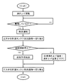
三方弁13が選択する流路を決定する三方弁制御手段14のフローチャートを、図2に示す。図2に示すように、除霜運転の開始が判定されると、三方弁13は貯湯タンク11下部に連通する流路18を選択するように切り換えられ、現在時刻が昼間時間帯(朝7時〜夜11時)であるか深夜時間帯(夜11時〜朝7時)であるかを確認する。
A flowchart of the three-way valve control means 14 for determining the flow path selected by the three-
現在時刻が昼間時間帯であれば、除霜運転終了直後の貯湯運転再開時に、温度センサー15によって検知された放熱器2通過後の沸き上げ温度である温水の温度と、目標沸き上げ温度との差が45℃以下(例えば、目標沸き上げ温度が70℃であれば、沸き上げ温度
25℃以上)であるか否かを判断し、温度差が45℃であれば、三方弁制御手段14は、三方弁13を貯湯タンク11上部に連通する流路17に切り換える。
If the current time is in the daytime period, when the hot water storage operation is resumed immediately after the defrosting operation is finished, the temperature of the hot water that is the boiling temperature after passing through the
一方、現在時刻が深夜時間帯であれば、温度センサー15によって検知された温度と目標沸き上げ温度との差が15℃以下(例えば、目標沸き上げ温度が70℃であれば、沸き上げ温度55℃以上)になると、三方弁制御手段14は、三方弁13を貯湯タンク11上部に連通する流路17に切り換える。
On the other hand, if the current time is midnight, the difference between the temperature detected by the
上記のように、三方弁13を制御して動作させることによって、昼間時間帯においては、目標沸き上げ温度に対して温度差が45℃以内である比較的温度が低めの中温水も、貯湯タンク11上部に還流することで、除霜運転を行うたびに上昇していた貯湯タンク11下部の冷水温度を低く維持し、放熱器2に供給される入水温度の上昇を抑制して、ヒートポンプサイクル5による貯湯運転時のエネルギー効率を向上できる。
As described above, by controlling the three-
一方、深夜時間帯においては、沸き上げ温度が目標沸き上げ温度に対して温度差が15℃以内である比較的温度が高めの中温水も、貯湯タンク11下部に還流されることで、貯湯タンク11上部の温水の温度低下が抑制され、深夜沸き上げ完了時における貯湯タンク11内に蓄熱される熱量を大きくすることができる。
On the other hand, in the midnight time zone, the hot water having a relatively high temperature whose boiling temperature is within a temperature difference of 15 ° C. with respect to the target boiling temperature is also returned to the lower part of the
このようにすることによって、必要な時間帯に大きな熱量を貯湯タンク11に蓄熱し、かつ貯湯運転時のエネルギー効率を高くして、消費電力量を低減することができる。
By doing so, a large amount of heat can be stored in the hot
本実施の形態によれば、上記の構成により、除霜運転終了直後の貯湯運転再開時に、昼間時間帯と深夜時間帯において、沸き上げ温度が予め定められた温度になると、貯湯タンク11の下部から上部に連通するように流路を切り換える。
According to the present embodiment, with the above-described configuration, when the boiling temperature reaches a predetermined temperature in the daytime time zone and midnight time zone when the hot water storage operation is resumed immediately after the defrosting operation is finished, the lower part of the hot
そして、深夜時間帯における流路切り換え温度を、昼間時間帯における流路切り換え温度よりも高くすることで、昼間時間帯においては、貯湯運転開始時や除霜運転後などに生成する中温水を貯湯タンク11上部に還流し、深夜時間帯においては、上記中温水を貯湯タンク11下部に還流することによって、必要な時間帯に大きな熱量を蓄熱しながらも、貯湯運転時に高いエネルギー効率を実現できるという効果を奏する。
Then, by setting the flow path switching temperature in the midnight hours higher than the flow path switching temperature in the daytime hours, during the daytime hours, the medium-temperature water generated at the start of the hot water storage operation or after the defrosting operation is stored. By returning to the upper part of the
(参考例1)
次に、本発明の参考例1におけるヒートポンプ給湯機の構成は、上記実施の形態1における構成と同一である。本参考例における三方弁13は、三方弁制御手段14によって、図3に示すようなフローチャートに従って、昼間時間帯と深夜時間帯において異なる制御方法により制御され動作する。
( Reference Example 1 )
Next, the configuration of the heat pump water heater in Reference Example 1 of the present invention is the same as the configuration in the first embodiment. The three-
昼間時間帯においては、除霜運転終了直後の貯湯運転再開時に、沸き上げ回路16に水を循環させるために循環ポンプ12が始動すると同時に、三方弁制御手段14によって三方弁13は貯湯タンク11の上部に連通する流路に切り換えられる。一方、深夜時間帯においては、除霜運転終了直後の貯湯運転再開時に、温度センサー15によって検知された温度が目標沸き上げ温度に対して温度差が15℃以内になると、三方弁制御手段14によって三方弁13は貯湯タンク11の上部に連通する流路に切り換えられる。
In the daytime period, when the hot water storage operation is resumed immediately after the end of the defrosting operation, the
上記のように三方弁13を動作させることによって、昼間時間帯においては、循環ポンプ12が始動し、除霜運転終了直後の貯湯運転再開時に生成する中温水が貯湯タンク11上部に還流され、除霜運転のたびに貯湯タンク11下部の冷水温度が上昇するのを抑制し、放熱器2に供給される入水温度の上昇を抑制して、ヒートポンプサイクル5による貯湯運転時のエネルギー効率を向上させる。一方、深夜時間帯においては、除霜運転終了直後
の貯湯運転再開時に、沸き上げ温度が目標沸き上げ温度に対して温度差が15℃以上である中温水は貯湯タンク11下部に還流され、貯湯タンク11上部の温水の温度低下が抑制され、深夜沸き上げ完了時における貯湯タンク11内に蓄熱される熱量を大きくすることができる。
By operating the three-
こうすることによって、必要な時間帯に大きな熱量を貯湯タンク11に蓄熱し、かつ貯湯運転時のエネルギー効率を高くして、消費電力量を低減することができる。
By doing so, a large amount of heat can be stored in the hot
本参考例によれば、上記の構成により、昼間時間帯においては、除霜運転終了直後の貯湯運転再開時に、循環ポンプの始動とともに貯湯タンク11の下部から上部に連通するように流路を切り換え、深夜時間帯においては、除霜運転終了直後の貯湯運転再開時に、沸き上げ温度が予め定められた温度以上になると、流路を切り換える三方弁13を備え、昼間時間帯においては除霜運転終了直後の貯湯運転再開時に生成する中温水を貯湯タンク11上部に還流し、深夜時間帯においては上記中温水を貯湯タンク11下部に還流することによって、必要な時間帯に大きな熱量を蓄熱しながらも、貯湯運転時に高いエネルギー効率を実現できるという効果を奏する。
According to this reference example , with the above configuration, in the daytime period, when the hot water storage operation is resumed immediately after the defrosting operation is completed, the flow path is switched so as to communicate from the lower part of the hot
(参考例2)
次に、本発明の参考例2におけるヒートポンプ給湯機の構成は、上記実施の形態1における構成に同じである。本参考例における三方弁13は、三方弁制御手段14によって、図4に示すようなフローチャートに従って、昼間時間帯と深夜時間帯において異なる制御方法により制御され動作する。
( Reference Example 2 )
Next, the configuration of the heat pump water heater in Reference Example 2 of the present invention is the same as the configuration in the first embodiment. The three-
昼間時間帯においては、除霜運転終了直後の貯湯運転再開時に、蒸発器に空気を導く送風手段6が始動すると同時に、三方弁制御手段14によって三方弁13は貯湯タンク11の上部に連通する流路に切り換えられる。一方、深夜時間帯においては、除霜運転終了直後の貯湯運転再開時に、温度センサー15によって検知された温度が目標沸き上げ温度に対して温度差が15℃以内になると、三方弁制御手段14によって三方弁13は貯湯タンク11の上部に連通する流路に切り換えられる。
In the daytime period, when the hot water storage operation is resumed immediately after the defrosting operation is started, the air blowing means 6 that guides air to the evaporator starts, and at the same time, the three-way valve control means 14 causes the three-
上記のように三方弁13を動作させることによって、昼間時間帯においては、送風手段6が始動し、除霜運転終了直後の貯湯運転再開時に生成する中温水が貯湯タンク11上部に還流されるために、貯湯タンク11下部の冷水温度の上昇が抑制され、放熱器2に供給される入水温度の上昇を抑制して、ヒートポンプサイクル5による貯湯運転時のエネルギー効率を向上させる。一方、深夜時間帯においては、除霜運転終了直後の貯湯運転再開時に、沸き上げ温度が目標沸き上げ温度に対して温度差が15℃以上である中温水は貯湯タンク11下部に還流され、貯湯タンク11上部の温水の温度低下が抑制され、深夜沸き上げ完了時における貯湯タンク11内に蓄熱される熱量を大きくすることができる。
By operating the three-
これによって、必要な時間帯に大きな熱量を貯湯タンク11に蓄熱し、かつ貯湯運転時のエネルギー効率を高くして、消費電力量を低減することができる。
As a result, a large amount of heat can be stored in the hot
本参考例によれば、上記の構成により、昼間時間帯においては、除霜運転終了直後の貯湯運転再開時に、送風手段6の始動とともに貯湯タンク11の下部から上部に連通するように流路を切り換え、深夜時間帯においては、除霜運転終了直後の貯湯運転再開時に、沸き上げ温度が予め定められた温度以上になると、流路を切り換える三方弁13を備え、昼間時間帯においては除霜運転終了直後の貯湯運転再開時に生成する中温水を貯湯タンク11上部に還流し、深夜時間帯においては上記中温水を貯湯タンク11下部に還流することによって、必要な時間帯に大きな熱量を蓄熱しながらも、貯湯運転時に高いエネルギー効率を実現できるという効果を奏する。
According to this reference example , with the above-described configuration, in the daytime period, when the hot water storage operation is resumed immediately after the defrosting operation is completed, the flow path is communicated from the lower part of the hot
本発明の貯湯式ヒートポンプ給湯機は、除霜運転終了直後の貯湯運転再開時において、高いエネルギー効率で貯湯運転を行うことを可能とし、かつ、必要な時間帯には貯湯タンク内に大きな熱量を蓄熱することも可能とする効果を有するので、ヒートポンプ給湯機の省エネルギー化および湯切れ防止に対して有用である。 The hot water storage type heat pump water heater of the present invention makes it possible to perform hot water storage operation with high energy efficiency when hot water storage operation is resumed immediately after the completion of the defrosting operation, and to generate a large amount of heat in the hot water storage tank in the required time zone. Since it has the effect of making it possible to store heat, it is useful for energy saving of the heat pump water heater and prevention of running out of hot water.
1 圧縮機
2 放熱器
3 膨張弁
4 蒸発器
5 ヒートポンプサイクル
6 送風手段
11 貯湯タンク
12 循環ポンプ
13 三方弁
14 三方弁制御手段
15 温度センサー
16 沸き上げ回路
DESCRIPTION OF
Claims (3)
Priority Applications (1)
| Application Number | Priority Date | Filing Date | Title |
|---|---|---|---|
| JP2009014023A JP5169873B2 (en) | 2009-01-26 | 2009-01-26 | Heat pump water heater |
Applications Claiming Priority (1)
| Application Number | Priority Date | Filing Date | Title |
|---|---|---|---|
| JP2009014023A JP5169873B2 (en) | 2009-01-26 | 2009-01-26 | Heat pump water heater |
Publications (2)
| Publication Number | Publication Date |
|---|---|
| JP2010169352A JP2010169352A (en) | 2010-08-05 |
| JP5169873B2 true JP5169873B2 (en) | 2013-03-27 |
Family
ID=42701676
Family Applications (1)
| Application Number | Title | Priority Date | Filing Date |
|---|---|---|---|
| JP2009014023A Expired - Fee Related JP5169873B2 (en) | 2009-01-26 | 2009-01-26 | Heat pump water heater |
Country Status (1)
| Country | Link |
|---|---|
| JP (1) | JP5169873B2 (en) |
Family Cites Families (5)
| Publication number | Priority date | Publication date | Assignee | Title |
|---|---|---|---|---|
| JP3932913B2 (en) * | 2002-01-29 | 2007-06-20 | ダイキン工業株式会社 | Heat pump water heater |
| JP2003279136A (en) * | 2002-03-19 | 2003-10-02 | Toto Ltd | Heat pump water heater |
| JP3919736B2 (en) * | 2003-11-18 | 2007-05-30 | 松下電器産業株式会社 | Start-up control device and start-up control method for heat pump water heater |
| JP4192875B2 (en) * | 2004-06-08 | 2008-12-10 | 株式会社デンソー | Heat pump type water heater |
| JP3992199B2 (en) * | 2004-08-31 | 2007-10-17 | 松下電器産業株式会社 | Hot water heater |
-
2009
- 2009-01-26 JP JP2009014023A patent/JP5169873B2/en not_active Expired - Fee Related
Also Published As
| Publication number | Publication date |
|---|---|
| JP2010169352A (en) | 2010-08-05 |
Similar Documents
| Publication | Publication Date | Title |
|---|---|---|
| US8919296B2 (en) | Hot-water supply system | |
| US20090250203A1 (en) | Hot Water Supply Apparatus | |
| CN103415747A (en) | Heat pump-type water heater | |
| EP2933579B1 (en) | Heat pump water heater | |
| JP2007278553A (en) | Water heater | |
| JP5181828B2 (en) | Heat pump water heater | |
| JP5655695B2 (en) | Hot water storage water heater | |
| JP3900186B2 (en) | Heat pump water heater | |
| JP2008224067A (en) | Heat pump hot water supply device | |
| JP2006250367A (en) | Heat pump water heater | |
| JP5169873B2 (en) | Heat pump water heater | |
| JP5575190B2 (en) | Water heater | |
| JP2005140439A (en) | Heat pump water heater | |
| JP3703995B2 (en) | Heat pump water heater | |
| JP5413328B2 (en) | Water heater | |
| JP5394314B2 (en) | Heat pump water heater | |
| JP4134969B2 (en) | Hot water storage type heat pump water heater | |
| JP5097054B2 (en) | Heat pump water heater | |
| JP3856025B2 (en) | Heat pump water heater | |
| JP2002340440A (en) | Heat pump hot-water supplier | |
| JP2009264650A (en) | Water heater | |
| JP5387102B2 (en) | Heat pump water heater | |
| JP4223468B2 (en) | Hot water storage hot water heater | |
| JP7441727B2 (en) | hot water storage system | |
| JP5498130B2 (en) | Boiling set temperature determination method of heat pump hot water storage type hot water supply and heating system |
Legal Events
| Date | Code | Title | Description |
|---|---|---|---|
| A621 | Written request for application examination |
Free format text: JAPANESE INTERMEDIATE CODE: A621 Effective date: 20110302 |
|
| RD01 | Notification of change of attorney |
Free format text: JAPANESE INTERMEDIATE CODE: A7421 Effective date: 20110413 |
|
| A977 | Report on retrieval |
Free format text: JAPANESE INTERMEDIATE CODE: A971007 Effective date: 20121017 |
|
| A131 | Notification of reasons for refusal |
Free format text: JAPANESE INTERMEDIATE CODE: A131 Effective date: 20121023 |
|
| A521 | Written amendment |
Free format text: JAPANESE INTERMEDIATE CODE: A523 Effective date: 20121112 |
|
| TRDD | Decision of grant or rejection written | ||
| A01 | Written decision to grant a patent or to grant a registration (utility model) |
Free format text: JAPANESE INTERMEDIATE CODE: A01 Effective date: 20121204 |
|
| A61 | First payment of annual fees (during grant procedure) |
Free format text: JAPANESE INTERMEDIATE CODE: A61 Effective date: 20121217 |
|
| FPAY | Renewal fee payment (event date is renewal date of database) |
Free format text: PAYMENT UNTIL: 20160111 Year of fee payment: 3 |
|
| LAPS | Cancellation because of no payment of annual fees |