JP5169767B2 - Radio communication apparatus, radio communication system, and signal switching method in radio communication system - Google Patents
Radio communication apparatus, radio communication system, and signal switching method in radio communication system Download PDFInfo
- Publication number
- JP5169767B2 JP5169767B2 JP2008297680A JP2008297680A JP5169767B2 JP 5169767 B2 JP5169767 B2 JP 5169767B2 JP 2008297680 A JP2008297680 A JP 2008297680A JP 2008297680 A JP2008297680 A JP 2008297680A JP 5169767 B2 JP5169767 B2 JP 5169767B2
- Authority
- JP
- Japan
- Prior art keywords
- wireless communication
- signal
- switching
- communication device
- output
- Prior art date
- Legal status (The legal status is an assumption and is not a legal conclusion. Google has not performed a legal analysis and makes no representation as to the accuracy of the status listed.)
- Expired - Fee Related
Links
Images


Classifications
-
- H—ELECTRICITY
- H04—ELECTRIC COMMUNICATION TECHNIQUE
- H04B—TRANSMISSION
- H04B10/00—Transmission systems employing electromagnetic waves other than radio-waves, e.g. infrared, visible or ultraviolet light, or employing corpuscular radiation, e.g. quantum communication
- H04B10/25—Arrangements specific to fibre transmission
- H04B10/2575—Radio-over-fibre, e.g. radio frequency signal modulated onto an optical carrier
- H04B10/25752—Optical arrangements for wireless networks
- H04B10/25753—Distribution optical network, e.g. between a base station and a plurality of remote units
-
- H—ELECTRICITY
- H04—ELECTRIC COMMUNICATION TECHNIQUE
- H04B—TRANSMISSION
- H04B1/00—Details of transmission systems, not covered by a single one of groups H04B3/00 - H04B13/00; Details of transmission systems not characterised by the medium used for transmission
- H04B1/02—Transmitters
- H04B1/04—Circuits
- H04B1/0466—Fault detection or indication
-
- H—ELECTRICITY
- H04—ELECTRIC COMMUNICATION TECHNIQUE
- H04B—TRANSMISSION
- H04B1/00—Details of transmission systems, not covered by a single one of groups H04B3/00 - H04B13/00; Details of transmission systems not characterised by the medium used for transmission
- H04B1/74—Details of transmission systems, not covered by a single one of groups H04B3/00 - H04B13/00; Details of transmission systems not characterised by the medium used for transmission for increasing reliability, e.g. using redundant or spare channels or apparatus
- H04B1/745—Details of transmission systems, not covered by a single one of groups H04B3/00 - H04B13/00; Details of transmission systems not characterised by the medium used for transmission for increasing reliability, e.g. using redundant or spare channels or apparatus using by-passing or self-healing methods
Abstract
Description
本発明は、無線通信装置、無線通信システム、及び無線通信システムにおける信号切替え方法に関する。 The present invention relates to a radio communication device, a radio communication system, and a signal switching method in the radio communication system.
図18は従来の無線基地局装置の構成例を示す図である(例えば、以下の非特許文献1)。無線基地局装置200は、ベースバンド信号に対する処理を行う無線制御装置(REC:Radio Equipment Controller)210と、無線信号に対する処理を行う無線装置(RE:Radio Equipment)220とを備える。無線制御装置210と無線装置220とは、光ファイバにより接続される。接続はCPRIによるインタフェースが用いられる。
FIG. 18 is a diagram illustrating a configuration example of a conventional radio base station apparatus (for example, Non-Patent
図19は、CPRI(Common Public Radio Interface)インタフェースを用いた従来の無線通信システムの構成例を示す図である(例えば、以下の特許文献1)。無線通信システム100は、第1の無線基地局装置2と、第2の無線基地局装置4と、各無線基地局装置2,4に接続された上位装置1,3とを備える。第1の無線基地局装置2と第2の無線基地局装置4は、無線制御装置21,51のインタフェース変換部213,513を介して互いに接続される。無線通信システム100は、アンテナ5を介して端末装置と無線通信を行う。無線通信システム100は、2つの無線サービスA,Bを端末装置に提供できる。
しかし、従来の無線通信システム100は、インタフェース変換部513で故障が発生した場合、無線サービスB対応の第2の無線制御装置51からの信号と、無線サービスA対応の第1の無線制御装置21からの信号とを無線装置52に出力できない。この場合、無線通信システム100はどちらの無線サービスも継続して端末装置に提供することができない。
However, in the conventional wireless communication system 100, when a failure occurs in the
そこで、一目的は、継続してサービスを提供することができる無線通信システム、無線通信装置、及び無線通信システムにおける信号切替え方法を提供することにある。 Accordingly, an object is to provide a radio communication system, a radio communication apparatus, and a signal switching method in the radio communication system that can continuously provide services.
一態様によれば、端末装置と無線通信を行う無線通信装置システムにおいて、第1の信号を処理する第1の無線通信装置と、第2の信号を処理し、前記第1及び第2の信号を合成または分離する第2の無線通信装置と、前記第2の無線通信装置から出力された前記第1及び第2の信号を増幅して前記端末装置に送信し、前記端末装置から受信した前記第1及び第2の信号を増幅して前記第2の無線通信装置に出力する共用アンプと、前記第1及び第2の無線通信装置と前記共用アンプとの間に接続され、前記第1または第2の無線通信装置で異常が発生した場合、前記第1または第2の無線通信装置の接続を切り離すように切替える切替装置とを備える。 According to an aspect, in a wireless communication device system that performs wireless communication with a terminal device, a first wireless communication device that processes a first signal, a second signal, and the first and second signals A second wireless communication device that combines or separates, and the first and second signals output from the second wireless communication device are amplified and transmitted to the terminal device, and received from the terminal device. A shared amplifier that amplifies the first and second signals and outputs them to the second wireless communication device; and is connected between the first and second wireless communication devices and the shared amplifier; And a switching device that switches to disconnect the connection of the first or second wireless communication device when an abnormality occurs in the second wireless communication device.
また、他の態様によれば、端末装置と無線通信を行う無線通信装置において、第1の信号と他の無線通信装置から出力された第2の信号とを合成し、合成された前記第1及び第2の信号を分離する無線制御部と、前記無線制御部から出力された前記第1及び第2の信号を増幅して前記端末装置に送信し、前記端末装置から受信した前記第1及び第2の信号を増幅して前記無線制御部に出力する共用アンプと、前記他の無線通信装置及び前記無線制御部と前記共用アンプとの間に接続され、前記他の無線基地局装置または前記無線制御部で異常が発生した場合、前記他の無線基地局装置または前記無線制御部の接続を切り離すように切替える切替部とを備える。 According to another aspect, in the wireless communication device that performs wireless communication with the terminal device, the first signal is combined with the second signal output from the other wireless communication device, and the first signal is combined. And a radio control unit that separates the second signal, and the first and second signals output from the radio control unit are amplified and transmitted to the terminal device, and the first and second signals received from the terminal device A shared amplifier that amplifies a second signal and outputs the amplified signal to the radio control unit, and the other radio communication device and the radio control unit and the common amplifier are connected, and the other radio base station device or the A switching unit that switches to disconnect the connection of the other radio base station device or the radio control unit when an abnormality occurs in the radio control unit.
さらに、他の態様によれば、第1の信号を処理する第1の無線通信装置と、第2の信号を処理し前記第1及び第2の信号を合成または分離する第2の無線通信装置と、前記第2の無線通信装置から出力された前記第1及び第2の信号を増幅して前記端末装置に送信し、前記端末装置から受信した前記第1及び第2の信号を増幅して前記第2の無線通信装置に出力する共用アンプと備える無線通信システムにおける信号切替え方法において、前記第1または第2の無線通信装置で異常が発生した場合、前記第1及び第2の無線通信装置と前記共用アンプとの間に接続される切替装置により前記第1または第2の無線通信装置の接続を切り離すように切替える。 Further, according to another aspect, a first wireless communication device that processes a first signal and a second wireless communication device that processes a second signal and combines or separates the first and second signals. And amplifying the first and second signals output from the second wireless communication device and transmitting them to the terminal device, and amplifying the first and second signals received from the terminal device. In a signal switching method in a wireless communication system including a shared amplifier that outputs to the second wireless communication device, when an abnormality occurs in the first or second wireless communication device, the first and second wireless communication devices And switching to disconnect the connection of the first or second wireless communication device by a switching device connected between the common amplifier and the shared amplifier.
継続してサービスを提供することができる無線通信システム、無線通信装置、及び無線通信システムにおける信号切替え方法を提供することができる。 It is possible to provide a wireless communication system, a wireless communication apparatus, and a signal switching method in the wireless communication system that can continuously provide services.
以下、図面を参照して実施するための最良の形態を説明する。 Hereinafter, the best mode for carrying out the invention will be described with reference to the drawings.
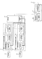
図1は、無線通信システム300の構成例を示す図である。無線通信システム300は、無線サービスA対応の第1の無線基地局装置(または無線通信装置)10と、無線サービスB対応の第2の無線基地局装置20と、無線装置(RE)24と、切替装置40とを備える。無線サービスAと無線サービスBとは異なる通信方式であり、無線通信システム300は異なる通信方式の信号を取り扱うことができる。たとえば、無線サービスAは旧サービス、無線サービスBは新サービスの通信方式である。
FIG. 1 is a diagram illustrating a configuration example of a wireless communication system 300. The radio communication system 300 includes a first radio base station apparatus (or radio communication apparatus) 10 compatible with the radio service A, a second radio
第1の無線基地局装置10は、第1の無線制御装置(REC)11を備える。第1の無線制御装置11は、第1の共通制御部111と、第1のベースバンド信号処理部112と、第1のインタフェース変換部113とを備える。
The first radio
一方、第2の無線基地局装置20は、第2の無線制御装置(REC)22を備える。第2の無線制御装置(REC)22は、第2の共通制御部221と、第2のベースバンド信号処理部222と、第2のインタフェース変換部223とを備える。
On the other hand, the second radio
第1及び第2の共通制御部111,221は、各無線基地局装置10,20に同期信号を配信する等により各無線基地局装置20内を制御したり、個々のユーザ設定等を行う。
The first and second
第1及び第2のベースバンド信号処理部112,222は、上位装置からの信号を例えばI信号、Q信号からなるベースバンド信号に変換し、第1及び第2のインタフェース変換部113,223からのベースバンド信号を上位装置に送信できるフォーマットに変換等を行う。
The first and second baseband
第1のインタフェース変換部113は、第1のCPRI処理部1131と、第1の変換部1132とを備える。
The first
第2のインタフェース変換部223は、第2のCPRI処理部2231と、第2の変換部2232と、第3の変換部2233と、第3のCPRI処理部2234と、サービス多重分離部2235と、第4の変換部2236と、第4のCPRI処理2237と、第5の変換部2238とを備える。
The second
第1及び第2のCPRI処理部1131,2231は、ベースバンド信号をCPRIフォーマットであるCPRI信号に変換してそれぞれ第1及び第2の変換部1132,2232に出力する。また、第1及び第2のCPRI処理部1131,2231は、第1及び第2の変換部1132,2232からのCPRI信号をベースバンド信号に変換等する。
The first and second
第1及び第2の変換部1132,2232は、第1及び第2のCPRI処理部1131,2231からのCPRI信号を光信号に変換し、光信号をCPRI信号に変換して第1及び第2のCPRI処理部1131,2231に出力等する。
The first and
第3及び第4の変換部2233,2236は、光信号を電気信号であるCPRI信号に変換して第3及び第4のCPRI処理部2234,2237に出力し、第3及び第4のCPRI処理部2234,2237からのCPRI信号を光信号に変換等する。
The third and
第3及び第4のCPRI処理部2234,2237は、CPRI信号をベースバンド信号に変換してサービス多重分離部2235に出力し、サービス多重分離部2235からのベースバンド信号をCPRI信号に変換等する。
The third and fourth
サービス多重分離部2235は、2つの無線サービスAおよびBに対応する2つのCPRI信号を多重または合成して第5の変換部2238に出力し、第5の変換部2238からの多重化されたCPRI信号を無線サービスごとに分離して出力する。
The
第5の変換部2238は多重化されたCPRI信号を光信号に変換して切替装置40に出力し、切替装置40からの光信号をCPRI信号に変換してサービス多重分離部2235に出力する。
The
無線装置24は、第3のインタフェース変換部241と、送受信増幅部242とを備える。
The
第3のインタフェース変換部241は、切替装置40からの光信号をCPRI信号に変換し、変換後のCPRI信号(多重化信号)から無線サービスAおよびBに対応したベースバンド信号を分離または抽出し送受信増幅器242に出力する。また、第3のインタフェース変換部241は、送受信増幅器242から出力された無線サービスAおよびBにそれぞれ対応したベースバンド信号を多重化し、光信号に変換等して切替装置40に出力する。
The third
送受信増幅器242は、第3のインタフェース変換部241からのベースバンド信号を変調し、増幅等してアンテナ5に出力する。また、送受信増幅器242は、アンテナ5を介して受信した2つの無線サービスAおよびBに対応する信号を増幅し、ダウンコンバート等して第3のインタフェース変換部241に出力する。
The transmission /
このように無線装置24または送受信増幅器242は、無線サービスAおよびBに対応する信号に対して共用して使用される共用アンプでもある。
As described above, the
アンテナ5は端末装置と2つの無線サービスAおよびBに対応する信号を送受信する。無線通信システム300は2つの無線サービスAおよびBを提供できる。
The
切替装置40は、第1の光スイッチ41と、第2の光スイッチ42と、第1及び第2の光カプラ43,45と、第6及び第7の変換部44,46と、信号モニタ/自律切替制御部(以下、信号モニタ部)47と、切替制御部48とを備える。
The
第1の光スイッチ41は、第1の変換部1132と第4の変換部2236との間に接続され、さらに第1の変換部1132と第2の光スイッチ42との間に接続される。第1の光スイッチ41は、切替制御部48からの切替制御信号に基づいて、第1の変換部1132からの無線サービスA対応の信号を第2の光スイッチ42または第4の変換部2236のいずれか一方にそれぞれ端子「a」または端子「b」を介して出力する。また、第1の光スイッチ41は、切替制御信号に基づいて第2の光スイッチ42からの信号または第4の変換部2236からの信号のいずれか一方を第1の変換部1132に出力する。
The first
第1の光カプラ43は、第1の無線基地局装置10と切替装置40との間に流れる信号を分岐(またはコピー)して第6の変換部44に出力する。第6の変換部44は、分岐した光信号を電気信号に変換し、信号モニタ部47に出力する。
The first
第2の光スイッチ42は、第5の変換部2238と無線装置24との間に接続され、さらに第1の光スイッチ41と無線装置24との間に接続される。第2の光スイッチ42は、切替制御部48からの切替制御信号に基づいて、第1の光スイッチ41からの無線サービスA対応の信号、または第5の変換部2238からの多重化信号のいずれか一方をそれぞれ端子「c」または「d」を介して無線装置24に出力する。または、第2の光スイッチ42は切替制御信号に基づいて、無線装置24からの信号を第5の変換部2238または第1の光スイッチ41に出力する。
The second
第2の光カプラ45は、第2の光スイッチ42と無線装置24との間に接続され、この間に流れる信号を分岐(またはコピー)する。第7の変換部46は光信号を電気信号に変換し、信号モニタ部47に出力する。
The second
信号モニタ部47は、第6または第7の変換部44,46からの信号に基づいて、第1の無線基地局装置10、または第2の無線制御装置22に異常が発生したか否かを検出し、その結果を切替制御部48に通知する。
The
切替制御部48は、信号モニタ部47からの通知に基づいて第1及び第2の光スイッチ41,42に切替制御信号を出力する。
The switching
次に、第1及び第2の光スイッチ41,42の切替動作を説明する。まず、下り方向(各無線基地局装置10,20から無線装置24への方向)について説明する。図2は切替動作の例を示すフローチャートである。
Next, the switching operation of the first and second
切替装置40は、起動すると(S10)、初期設定を行う(S11)。例えば、切替制御部48は切替装置40の起動を検出すると、初期設定として、第1の光スイッチ41を端子「b」、第2の光スイッチ42を端子「d」に切替えるよう切替制御信号を出力する。第1及び第2の光スイッチ41,42は、切替制御信号に基づいてスイッチが切替わる。図1は初期設定時のスイッチ切替え例を示す。
When the
この場合、第1の基地局装置10から出力される無線サービスAの信号は、第1の光スイッチ41を介して無線サービスB対応の第2の無線基地局装置20に出力される。また、無線サービスAとBの2つの多重化された信号は第2の無線基地局装置20から第2の光スイッチ42を介して無線装置24に出力される。この場合、アンテナ5からは2つの無線サービスA、Bの信号が送信されるため、無線通信システム300は2つの無線サービスA、Bを端末装置に提供できる。
In this case, the signal of the radio service A output from the first
次いで、切替装置40の信号モニタ部47は、第2の光スイッチ42から出力される多重化された信号に対してモニタを開始する(S12)。
Next, the
そして、信号モニタ部47は第2の光スイッチ42から出力される信号の異常を検出すると(S13でYes)、切替制御部48に異常を検出したことを通知する(S14)。
When the
切替制御部48は、この通知を受けて、第1の光スイッチ41を端子「b」から端子「a」に、第2の光スイッチ42を端子「d」から端子「c」に切替えるように各スイッチ41,42に切替制御信号を出力する。
Upon receiving this notification, the switching
図3はスイッチ切替後の無線通信システム300の構成例を示す図である。スイッチ切替後は、無線サービスA対応の信号が第1の光スイッチ41から第2の光スイッチ42に出力され、さらに第2の光スイッチ42から無線装置24に出力される。無線サービスA対応の信号は第2の無線基地局装置20に出力されず、また第2の無線基地局装置20からの出力信号は無線装置24に出力されない。スイッチの切替により、第2の無線基地局装置20が無線通信システム300から切り離され、無線サービスA対応の信号が無線サービスB対応の第2の無線基地局装置20の影響を受けずに無線装置24に出力される。
FIG. 3 is a diagram illustrating a configuration example of the wireless communication system 300 after switch switching. After the switch is switched, a signal corresponding to the wireless service A is output from the first
図2に戻り、信号モニタ部47は異常を検出しないとき(S13でNo)、異常を検出するまで処理を繰り返す(S13のループ)。
Returning to FIG. 2, when the signal monitor 47 does not detect any abnormality (No in S13), the
このように、無線通信システム300は、第2の無線基地局装置20から出力される信号の異常を検出すると、切替装置40により無線サービスA対応の信号を出力するようにしている。従って、無線通信システム300は、無線サービスB対応の第2の無線制御装置22で故障等が発生しても継続してサービスを提供できる。
As described above, when the radio communication system 300 detects an abnormality in the signal output from the second radio
次に異常検出の例について説明する。図4はCPRIプロトコルの例を示す図である。CPRIプロトコルのレイヤ1では、コネクタを外す等により光インタフェースの切断が検出できる。信号モニタ部47はこの切断を示す信号を受信することにより異常を検出できる。これ以外にも、信号モニタ部47は、例えばレイヤ2の「HDLC」を利用して異常を検出できる。「HDLC」の例の場合、リンクの切断やプロトコル異常が発生したときに「HDLC」フィールドにはかかる異常を示す情報が挿入されるため、信号モニタ部47がこれを検出することで異常を検出できる。さらに、信号モニタ部47は、例えば「Vender Specific」や、「Control&Management Plane」を用いて診断用データや各ベンダ独自のデータを監視し、異常を示すデータを検出することでも検出可能である。各フィールドへの情報の挿入は、例えばサービス多重分離部2235または第5の変換部2238等で行われる。
Next, an example of abnormality detection will be described. FIG. 4 is a diagram illustrating an example of the CPRI protocol. In
上述した例は、信号モニタ部47により異常を検出した例である。この場合、信号モニタ部47は、例えば第2の無線制御装置22のサービス多重分離部2235から第2の光スイッチ42の前段までの異常を検出できる。
The example described above is an example in which an abnormality is detected by the
一方、第2の無線基地局装置20における、第2の共通制御部221及び第4の変換部2236からサービス多重分離部2235の前段までの異常は、例えばサービス多重分離部2235で検出できる。サービス多重分離部2235は、CPRI信号を取り扱うため、図4に示した例で異常を検出できる。このような場合において、異常を検出した場合の動作について説明する。図5はその動作例を示すフローチャートである。
On the other hand, an abnormality from the second
サービス多重分離部2235は、無線サービスA側の信号、すなわち第4の変換部2236から第4のCPRI処理部2237まで入出力される信号の異常を検出した場合(S20,S21でYes)、無線サービスA側の信号を多重せず無線サービスB側の信号を出力する(S22)。
When the
一方、サービス多重分離部2235は、無線サービスB側の信号、すなわち、第2の共通制御部221から第3のCPRI処理部2234まで入出力される信号の異常を検出した場合(S21でYes)、無線サービスB側の信号を多重せず、無線サービスA側の信号を出力する(S22)。
On the other hand, when the
サービス多重分離部2235で異常検出が行われる場合、切替装置40は初期設定のままである。ただし、サービス多重分離部2235で異常検出を行わない場合や異常検出ができない場合などは、上述した切替装置40の信号モニタ部47で異常検出が行われてもよい。
When abnormality detection is performed in the
切替装置40は、第1の無線基地局装置10の異常も監視することができる。信号モニタ部47は、第1の光カプラ43及び第6の変換部44を経由する信号を監視し、初期設定は図1に示すように切替を行う。信号モニタ部47は異常を検出した場合、その旨を切替制御部48に通知する。切替制御部48は、第1の光スイッチ41を端子「a」、第2の光スイッチ42を端子「d」に切替えるように切替制御信号を出力する。
The switching
図6は切替後の無線通信システム300の構成例を示す図である。無線サービスA対応の信号は第1の光スイッチ41を介して第2の光スイッチ42に出力されるものの、第2の光スイッチ42は端子「d」側に切替えられているため、第2の光スイッチ42から出力されない。また、無線サービスA対応の信号は第2の無線基地局装置20にも送信されない。結局、無線サービスB対応の信号が第2の光スイッチ42から無線装置24に出力される。
FIG. 6 is a diagram illustrating a configuration example of the wireless communication system 300 after switching. Although the signal corresponding to the wireless service A is output to the second
よって、切替装置40は第1の無線基地局装置10からの信号の異常を検出した場合、第2の無線基地局装置20からの信号を無線装置24に出力するため、無線通信システム300は継続してサービスを提供できる。
Therefore, when the
次に上り方向の動作等について説明する。図7は上り方向における切替動作の例を示すフローチャートである。 Next, the upward operation and the like will be described. FIG. 7 is a flowchart showing an example of the switching operation in the upward direction.
切替装置40は、起動すると(S40)、初期設定を行う(S41)。例えば、切替制御部48は切替装置40の起動を検出すると、第1の光スイッチ41を端子「b」、第2の光スイッチ42を端子「d」に切替えるよう切替制御信号を出力する。各光スイッチ41,42は各端子にスイッチが切替わる。図1は初期設定時のスイッチ切替例を示す。
When the
この場合、無線装置24からの信号は、第2の光スイッチ42を介して第2の無線制御装置22に出力される。また、第2の無線基地局装置20から出力される無線サービスA対応の信号は第1の光スイッチ41を介して第1の無線基地局装置10に出力される。
In this case, a signal from the
次いで、切替装置40の信号モニタ部47は、第1の光スイッチ41から出力される信号、すなわち第1の光カプラ43及び第6の変換部44から出力される信号の監視を開始する(S42)。
Next, the
そして、信号モニタ部47は第1の光スイッチ41から出力される信号の異常を検出すると(S43でYes)、切替制御部48に異常を検出したことを通知する(S44)。
When the
切替制御部48は、この通知を受けて、第1の光スイッチ41を端子「a」に、第2の光スイッチ42を端子「c」に切替えるように各スイッチ41,42に切替制御信号を出力する。スイッチ切替後の構成例を図3に示す。
Upon receiving this notification, the switching
無線装置24からの信号は、第2の光スイッチ42から第1の光スイッチ41を経由して、第1の無線基地局装置10に出力される。2つのスイッチ41,42により、サービスB対応の第2の無線制御装置22と無線装置24との接続が切り離される。第2の無線制御装置22で故障等が発生しても、無線装置24からの信号は第1の無線基地局装置10に出力できる。よって、無線通信システム300は上り方向でも端末装置に対して継続したサービスを提供できる。
A signal from the
図7に戻り、信号モニタ部47は第6の変換部44からの信号に異常を検出しないとき(S43でNo)、異常を検出するまで処理を繰り返す(S43のループ)。 Returning to FIG. 7, when the signal monitor 47 does not detect any abnormality in the signal from the sixth converter 44 (No in S43), the signal monitor 47 repeats the process until an abnormality is detected (S43 loop).
なお、第2の無線制御装置22のサービス多重分離部2235から第4の変換部2236の間で故障等により異常が発生した場合、信号モニタ部47は第1の光スイッチ41の出力を監視することで異常を検出できる。また、第2の無線制御装置22のサービス多重分離部2235より前段で異常が発生した発生した場合、サービス多重分離部2235で異常を検出することができる。この場合、検出した異常の発生をサービス多重分離部2235が切替装置40に通知できるようにするために、例えば、サービス多重分離部2235と切替制御部48とを制御線で接続してもよい。図8はその構成例を示す図である。切替制御部48は異常発生の通知を受けると、同図に示すように第2の無線制御装置22の接続を切り離すように切替えを行う。
When an abnormality occurs between the
次に他の実施例について説明する。例えば、切替装置40は、上位装置からの指示に基づいて切替えが行われてもよい。図9〜図11はこのような場合の無線通信システム300の構成例等を示す図である。
Next, another embodiment will be described. For example, the switching
図9に示すように、無線通信システム300はさらに第1及び第2の上位装置60,80を備える。第1の上位装置60は無線サービスA対応の第1の無線基地局装置10、第2の上位装置80は無線サービスB対応の第2の無線基地局装置20に接続される。さらに、第1及び第2の共通制御部111,221はそれぞれ切替装置40の切替制御部48と制御線で接続される。
As shown in FIG. 9, the wireless communication system 300 further includes first and second
図10は、第1または第2の共通制御部111,221における切替動作の例を示すフローチャートである。図10は上り方向及び下り方向のどちらも含まれるフローチャートである。
FIG. 10 is a flowchart illustrating an example of the switching operation in the first or second
無線サービスAおよびB対応の第1及び第2の無線基地局装置10,20が起動すると(S50)、第1または第2の共通制御部111,221は、第1または第2の上位装置60,80から切替装置40への制御信号を受信したか否かを判定する(S51)。
When the first and second radio
第1または第2の共通制御部111,221は、制御信号を受信したとき(S51でYes)、制御信号に含まれる切替指示を切替制御部48に制御線を介して通知する(S52)。これにより、切替装置40は第1または第2の上位装置60,80からの制御により切替が行われる。例えば図3や図6に示すように、第1または第2の無線制御装置11,22からの信号が無線装置24に出力されるように切替が行われる。このような切替は、例えばメンテナンスや故障等の原因究明のために行われる。
When receiving the control signal (Yes in S51), the first or second
一方、第1または第2の共通制御部111,221は、制御信号を受信しないとき(S51でNo)、自装置異常による切替装置40の制御があるか否かを判定する(S53)。例えば、第1及び第2の共通制御部111,221は、それぞれ第1及び第2の無線基地局装置10,20の各部で故障等の異常が発生したときに異常を示す信号を検出できる。これを受信したか否かで本処理は判定できる。
On the other hand, when the first or second
自装置の異常による切替装置40への制御がある場合(S53でYes)、第1または第2の共通制御部111,221は切替制御部48に切替を指示する(S54)。切替は、例えば、第2の共通制御部221が第2の無線基地局装置20の異常を検出した場合、第1の光スイッチ41を端子「a」、第2の光スイッチ42を端子「c」に切替えるよう切替制御部48に指示する。これにより、例えば図3に示すように、無線サービスB対応の第2の無線制御装置22が無線通信システム300から切り離すことができる。
When there is control over the switching
図11は切替装置40における切替動作の例を示すフローチャートである。図11も下り方向及び上り方向どちらも含まれるフローチャートである。
FIG. 11 is a flowchart illustrating an example of the switching operation in the
切替装置40の起動により(S60)、切替装置40は初期設定を行う(S61)。例えば、切替装置40は第1の光スイッチ41を端子「b」、第2の光スイッチ42を端子「d」にする。
When the
次いで、信号モニタ部47と切替制御部48は信号の監視を行う(S62)。
Next, the
次いで、切替制御部48は、第1または第2の無線基地局装置10,20の第1または第2の共通制御部111,221から切替指示を受信すると(S63でYes)、その指示内容に従い第1及び第2の光スイッチ41,42へ切替制御信号を出力する(S64)。これにより、例えば図3や図6に示すような切替が行われる。
Next, when the switching
一方、第1及び第2の共通制御部111,221から切替指示を受信しないとき(S63でNo)、受信するまで本処理を繰り返す。
On the other hand, when a switching instruction is not received from the first and second
他の実施例として、切替装置40が第2の無線基地局装置20の外部ではなく内部にあってもよい。図12及び図13はかかる場合の無線通信システム300の構成例を示す図である。第2の無線基地局装置20は信号切り替え部50を備える。図12に示すように、信号切り替え部50と上述した切替装置40は同一構成である。
As another example, the switching
さらに、他の実施例として、第2の無線基地局装置20の第2のインタフェース部223が切替装置40内部にあってもよい。図14及び図15はかかる例における無線通信システム300の構成例を示す図である。切替装置40はさらに第2のインタフェース変換部223を備える。
Furthermore, as another embodiment, the
通常動作時、第1及び第2の光スイッチ41,42は、図14に示すように、それぞれ端子「b」及び「d」に切替えられる。一方、第2の無線制御装置22や第2のインタフェース変換部223で異常が発生した場合、図15に示すように、第1及び第2の光スイッチ41,42は、それぞれ端子「a」及び「c」に切替えられる。第1の無線基地局装置10で異常が発生した場合も、図6に示すように、第1及び第2の光スイッチ41,42はそれぞれ端子「a」及び「c」に切替えられる。本例も、異常が発生しても継続して無線サービスを提供できる。
During normal operation, the first and second
さらに、他の実施例として、無線装置24は第2の無線基地局装置20内に設けられていてもよい。図16及び図17は無線通信システム300の本例における構成例を示す図である。図16に示すように、第2の無線基地局装置20はさらに無線装置24を備える。また、図17に示すように、第2の無線基地局装置20は無線装置24と信号切替部50とをさらに備えてもよい。
Furthermore, as another embodiment, the
以上まとめると付記のようになる。 The above is summarized as an appendix.
(付記1)
端末装置と無線通信を行う無線通信装置システムにおいて、
第1の信号を処理する第1の無線通信装置と、
第2の信号を処理し、前記第1及び第2の信号を合成または分離する第2の無線通信装置と、
前記第2の無線通信装置からの前記第1及び第2の信号を増幅して前記端末装置に送信し、前記端末装置から受信した前記第1及び第2の信号を増幅して前記第2の無線通信装置に出力する共用アンプと、
前記第1及び第2の無線通信装置と前記共用アンプとの間に接続され、前記第1または第2の無線通信装置で異常が発生した場合、前記第1または第2の無線通信装置の接続を切り離すように切替える切替装置と、
を備えることを特徴とする無線通信システム。
(Appendix 1)
In a wireless communication device system that performs wireless communication with a terminal device,
A first wireless communication device for processing a first signal;
A second wireless communication device that processes a second signal and combines or separates the first and second signals;
The first and second signals from the second wireless communication device are amplified and transmitted to the terminal device, and the first and second signals received from the terminal device are amplified and the second signal A shared amplifier that outputs to the wireless communication device;
Connected between the first and second wireless communication devices and the shared amplifier, and when an abnormality occurs in the first or second wireless communication device, connection of the first or second wireless communication device A switching device that switches to disconnect
A wireless communication system comprising:
(付記2)
前記切替装置は、第1及び第2の切替部を備え、
前記第2の無線通信装置で異常が発生した場合、前記第1の切替部は前記第1の無線通信装置から出力された前記第1の信号を前記第2の切替部に出力するように切替え、前記第2の切替部は前記第1の切替部から出力された前記第1の信号を前記共用アンプに出力するように切替えることで、前記第2の無線通信装置の接続を切り離すことを特徴とする付記1記載の無線通信システム。
(Appendix 2)
The switching device includes first and second switching units,
When an abnormality occurs in the second wireless communication device, the first switching unit switches to output the first signal output from the first wireless communication device to the second switching unit. The second switching unit disconnects the connection of the second wireless communication device by switching the first signal output from the first switching unit to output to the shared amplifier. The wireless communication system according to
(付記3)
前記切替装置は、第1及び第2の切替部を備え、
前記第2の無線通信装置で異常が発生した場合、前記第2の切替部は前記共用アンプから出力された前記第1及び第2の信号を前記第1の切替部に出力するように切替え、前記第1の切替部は前記第1の切替部から出力された前記第1及び第2の信号を前記第1の無線通信装置に出力するように切替えることで、前記第2の無線通信装置の接続を切り離すことを特徴とする付記1記載の無線通信システム。
(Appendix 3)
The switching device includes first and second switching units,
When an abnormality occurs in the second wireless communication device, the second switching unit switches to output the first and second signals output from the shared amplifier to the first switching unit, The first switching unit switches the first and second signals output from the first switching unit to output to the first wireless communication device, thereby enabling the second wireless communication device to The wireless communication system according to
(付記4)
前記切替装置は、第1及び第2の切替部を備え、
前記第1の無線通信装置で異常が発生した場合、前記第1の切替部は前記第1の無線通信装置から出力された前記第1の信号を前記第2の切替部に出力するように切替え、前記第2の切替部は前記第2の無線通信装置から出力された前記第2の信号を前記共用アンプに出力するように切替えることを特徴とする付記1記載の無線通信システム。
(Appendix 4)
The switching device includes first and second switching units,
When an abnormality occurs in the first wireless communication device, the first switching unit switches to output the first signal output from the first wireless communication device to the second switching unit. The wireless communication system according to
(付記5)
前記切替装置は、第1及び第2の切替部を備え、
前記第1の無線通信装置で異常が発生した場合、前記第2の切替部は前記共用アンプから出力された前記第1及び第2の信号を前記第2の無線通信装置に出力するように切替え、前記第1の切替部は前記第2の切替部と接続されるように切替えることを特徴とする付記1記載の無線通信システム。
(Appendix 5)
The switching device includes first and second switching units,
When an abnormality occurs in the first wireless communication device, the second switching unit switches to output the first and second signals output from the shared amplifier to the second wireless communication device. The wireless communication system according to
(付記6)
前記切替装置は、前記第1の無線通信装置と前記切替装置との間で入出力される信号または前記切替装置と前記無線装置との間で入出力される信号の異常を検出する検出部を備え、
前記第1または前記第2の無線通信装置の異常は前記検出部により検出されることを特徴とする付記1記載の無線通信システム。
(Appendix 6)
The switching device includes a detection unit that detects an abnormality of a signal input / output between the first wireless communication device and the switching device or a signal input / output between the switching device and the wireless device. Prepared,
The wireless communication system according to
(付記7)
前記切替装置は、前記第1の無線通信装置で異常が発生したことを示す信号を前記第1の無線通信装置から受信することで前記第1の無線通信装置の異常を検出することを特徴とする付記5記載の無線通信システム。
(Appendix 7)
The switching device detects an abnormality of the first wireless communication device by receiving a signal indicating that an abnormality has occurred in the first wireless communication device from the first wireless communication device. The wireless communication system according to
(付記8)
さらに、前記第1の無線通信装置に接続された第1の上位装置と、前記第2の無線通信装置に接続された第2の上位装置とを備え、
前記切替装置は、前記第1または第2の上位装置からの指示に基づいて、前記第1または前記第2の無線通信装置の接続を切り離すように接続を切替えることを特徴とする付記1記載の無線通信システム。
(Appendix 8)
And a first host device connected to the first wireless communication device and a second host device connected to the second wireless communication device,
The switching device switches the connection so as to disconnect the connection of the first or second wireless communication device based on an instruction from the first or second host device. Wireless communication system.
(付記9)
前記切替装置は前記第2の無線通信装置に設けられていることを特徴とする付記1記載の無線通信システム。
(Appendix 9)
The wireless communication system according to
(付記10)
前記第2の無線通信装置は、前記第2の信号を処理する無線制御部と、前記第1及び第2の信号を合成または分離するインタフェース変換部とを備え、
前記インタフェース変換部は前記切替装置と接続されることを特徴とする付記1記載の無線通信システム。
(Appendix 10)
The second wireless communication apparatus includes a wireless control unit that processes the second signal, and an interface conversion unit that combines or separates the first and second signals,
The wireless communication system according to
(付記11)
前記インタフェース変換部は前記切替装置に設けられていることを特徴とする付記10記載の無線通信システム。
(Appendix 11)
The wireless communication system according to
(付記12)
前記第1の信号は第1の通信方式に対応する信号であり、前記第2の信号は第2の通信方式に対応する信号であることを特徴とする付記1記載の無線通信システム。
(Appendix 12)
The wireless communication system according to
(付記13)
端末装置と無線通信を行う無線通信装置において、
第1の信号と他の無線通信装置から出力された第2の信号とを合成し、合成された前記第1及び第2の信号を分離する無線制御部と、
前記無線制御部から出力された前記第1及び第2の信号を増幅して前記端末装置に送信し、前記端末装置から受信した前記第1及び第2の信号を増幅して前記無線制御部に出力する共用アンプと、
前記他の無線通信装置及び前記無線制御部と前記共用アンプとの間に接続され、前記他の無線基地局装置または前記無線制御部で異常が発生した場合、前記他の無線基地局装置または前記無線制御部の接続を切り離すように切替える切替部と、
を備えることを特徴とする無線通信装置。
(Appendix 13)
In a wireless communication device that performs wireless communication with a terminal device,
A wireless control unit that combines the first signal and the second signal output from another wireless communication device, and separates the combined first and second signals;
The first and second signals output from the radio control unit are amplified and transmitted to the terminal device, and the first and second signals received from the terminal device are amplified and transmitted to the radio control unit. A shared amplifier to output,
When the other radio communication device and the radio control unit are connected between the shared amplifier and an abnormality occurs in the other radio base station device or the radio control unit, the other radio base station device or the A switching unit that switches to disconnect the wireless control unit;
A wireless communication apparatus comprising:
(付記14)
第1の信号を処理する第1の無線通信装置と、第2の信号を処理し前記第1及び第2の信号を合成または分離する第2の無線通信装置と、前記第2の無線通信装置からの前記第1及び第2の信号を増幅して前記端末装置に送信し、前記端末装置から受信した前記第1及び第2の信号を増幅して前記第2の無線通信装置に出力する共用アンプと備える無線通信システムにおける信号切替え方法において、
前記第1または第2の無線通信装置で異常が発生した場合、前記第1及び第2の無線通信装置と前記共用アンプとの間に接続される切替装置により前記第1または第2の無線通信装置の接続を切り離すように切替える、
ことを特徴とする信号切替え方法。
(Appendix 14)
A first wireless communication device that processes a first signal; a second wireless communication device that processes a second signal and combines or separates the first and second signals; and the second wireless communication device The first and second signals from the terminal are amplified and transmitted to the terminal device, and the first and second signals received from the terminal device are amplified and output to the second wireless communication device In a signal switching method in a wireless communication system provided with an amplifier,
When an abnormality occurs in the first or second wireless communication device, the first or second wireless communication is performed by a switching device connected between the first and second wireless communication devices and the shared amplifier. Switch to disconnect the device,
A signal switching method characterized by that.
10 第1の無線基地局装置、 11 第1の無線制御装置(REC)、 20 第2の無線基地局装置、 22 第2の無線制御装置(REC)、 24 無線装置(RE)、 40 切替装置、 41 第1の光スイッチ、 42 第2の光スイッチ、 43,45 第1,第2の光カプラ、 44,46 第6,第7の変換部、 47 信号モニタ部、 48 切替制御部、 60,80 第1,第2の上位装置、 50 信号切り替え部、 111,221 第1,第2の共通制御部、 112,222 第1,第2のベースバンド信号処理部、 113,223 第1,第2のインタフェース変換部、 300 無線通信システム、 1131,2231,2234,2237 第1,第2,第3,第4のCPRI処理部、 1132,2232,2233,2236,2238 第1,第2,第3,第4,第5の変換部、 2235 サービス多重分離部
DESCRIPTION OF
Claims (9)
第1の信号を処理する第1の無線通信装置と、
第2の信号を処理し、前記第1及び第2の信号を合成または分離する第2の無線通信装置と、
前記第2の無線通信装置から出力された前記第1及び第2の信号を増幅して前記端末装置に送信し、前記端末装置から受信した前記第1及び第2の信号を増幅して前記第2の無線通信装置に出力する共用アンプと、
前記第1及び第2の無線通信装置と前記共用アンプとの間に接続され、前記第1または第2の無線通信装置で異常が発生した場合、前記第1または第2の無線通信装置の接続を切り離すように切替える切替装置と、
を備え、
前記切替装置は、第1及び第2の切替部を備え、
前記第2の無線通信装置で異常が発生した場合、前記第1の切替部は前記第1の無線通信装置から出力された前記第1の信号を前記第2の切替部に出力するように切替え、前記第2の切替部は前記第1の切替部から出力された前記第1の信号を前記共用アンプに出力するように切替えることで、前記第2の無線通信装置の接続を切り離すことを特徴とする無線通信システム。 In a wireless communication device system that performs wireless communication with a terminal device,
A first wireless communication device for processing a first signal;
A second wireless communication device that processes a second signal and combines or separates the first and second signals;
The first and second signals output from the second wireless communication device are amplified and transmitted to the terminal device, and the first and second signals received from the terminal device are amplified and the first signal is amplified. A shared amplifier that outputs to the two wireless communication devices;
Connected between the first and second wireless communication devices and the shared amplifier, and when an abnormality occurs in the first or second wireless communication device, connection of the first or second wireless communication device A switching device that switches to disconnect
Equipped with a,
The switching device includes first and second switching units,
When an abnormality occurs in the second wireless communication device, the first switching unit switches to output the first signal output from the first wireless communication device to the second switching unit. The second switching unit disconnects the connection of the second wireless communication device by switching the first signal output from the first switching unit to output to the shared amplifier. A wireless communication system.
第1の信号を処理する第1の無線通信装置と、
第2の信号を処理し、前記第1及び第2の信号を合成または分離する第2の無線通信装置と、
前記第2の無線通信装置から出力された前記第1及び第2の信号を増幅して前記端末装置に送信し、前記端末装置から受信した前記第1及び第2の信号を増幅して前記第2の無線通信装置に出力する共用アンプと、
前記第1及び第2の無線通信装置と前記共用アンプとの間に接続され、前記第1または第2の無線通信装置で異常が発生した場合、前記第1または第2の無線通信装置の接続を切り離すように切替える切替装置と、
を備え、
前記切替装置は、第1及び第2の切替部を備え、
前記第2の無線通信装置で異常が発生した場合、前記第2の切替部は前記共用アンプから出力された前記第1及び第2の信号を前記第1の切替部に出力するように切替え、前記第1の切替部は前記第2の切替部から出力された前記第1及び第2の信号を前記第1の無線通信装置に出力するように切替えることで、前記第2の無線通信装置の接続を切り離すことを特徴とする無線通信システム。 In a wireless communication device system that performs wireless communication with a terminal device,
A first wireless communication device for processing a first signal;
A second wireless communication device that processes a second signal and combines or separates the first and second signals;
The first and second signals output from the second wireless communication device are amplified and transmitted to the terminal device, and the first and second signals received from the terminal device are amplified and the first signal is amplified. A shared amplifier that outputs to the two wireless communication devices;
Connected between the first and second wireless communication devices and the shared amplifier, and when an abnormality occurs in the first or second wireless communication device, connection of the first or second wireless communication device A switching device that switches to disconnect
With
The switching device includes first and second switching units,
When an abnormality occurs in the second wireless communication device, the second switching unit switches to output the first and second signals output from the shared amplifier to the first switching unit, The first switching unit switches the first and second signals output from the second switching unit to output to the first wireless communication device, whereby the second wireless communication device A wireless communication system characterized by disconnecting a connection.
第1の信号を処理する第1の無線通信装置と、
第2の信号を処理し、前記第1及び第2の信号を合成または分離する第2の無線通信装置と、
前記第2の無線通信装置から出力された前記第1及び第2の信号を増幅して前記端末装置に送信し、前記端末装置から受信した前記第1及び第2の信号を増幅して前記第2の無線通信装置に出力する共用アンプと、
前記第1及び第2の無線通信装置と前記共用アンプとの間に接続され、前記第1または第2の無線通信装置で異常が発生した場合、前記第1または第2の無線通信装置の接続を切り離すように切替える切替装置と、
を備え、
前記切替装置は、第1及び第2の切替部を備え、
前記第1の無線通信装置で異常が発生した場合、前記第1の切替部は前記第1の無線通信装置から出力された前記第1の信号を前記第2の切替部に出力するように切替え、前記第2の切替部は前記第2の無線通信装置から出力された前記第2の信号を前記共用アンプに出力するように切替えることを特徴とする無線通信システム。 In a wireless communication device system that performs wireless communication with a terminal device,
A first wireless communication device for processing a first signal;
A second wireless communication device that processes a second signal and combines or separates the first and second signals;
The first and second signals output from the second wireless communication device are amplified and transmitted to the terminal device, and the first and second signals received from the terminal device are amplified and the first signal is amplified. A shared amplifier that outputs to the two wireless communication devices;
Connected between the first and second wireless communication devices and the shared amplifier, and when an abnormality occurs in the first or second wireless communication device, connection of the first or second wireless communication device A switching device that switches to disconnect
With
The switching device includes first and second switching units,
When an abnormality occurs in the first wireless communication device, the first switching unit switches to output the first signal output from the first wireless communication device to the second switching unit. The wireless communication system, wherein the second switching unit performs switching so as to output the second signal output from the second wireless communication device to the shared amplifier.
第1の信号と他の無線通信装置から出力された第2の信号とを合成し、または合成された前記第1及び第2の信号を分離して、分離した前記第2の信号を前記他の無線通信装置に出力する無線制御部と、
前記無線制御部から出力された前記第1及び第2の信号を増幅して前記端末装置に送信し、前記端末装置から受信した前記第1及び第2の信号を増幅して前記無線制御部に出力する共用アンプと、
前記他の無線通信装置及び前記無線制御部と前記共用アンプとの間に接続され、前記他の無線通信装置または前記無線制御部で異常が発生した場合、前記他の無線通信装置または前記無線制御部の接続を切り離すように切替える切替部と、
を備え、
前記切替装置は、第1及び第2の切替部を備え、
前記無線制御部で異常が発生した場合、前記第1の切替部は前記他の無線通信装置から出力された前記第2の信号を前記第2の切替部に出力するように切替え、前記第2の切替部は前記第1の切替部から出力された前記第2の信号を前記共用アンプに出力するように切替えることで、前記無線制御部の接続を切り離すことを特徴とする無線通信装置。 In a wireless communication device that performs wireless communication with a terminal device,
The first signal and the second signal output from another wireless communication device are combined, or the combined first and second signals are separated and the separated second signal is used as the other signal. A wireless control unit for outputting to the wireless communication device ;
The first and second signals output from the radio control unit are amplified and transmitted to the terminal device, and the first and second signals received from the terminal device are amplified and transmitted to the radio control unit. A shared amplifier to output,
The other radio communication device or the radio control unit and the shared amplifier are connected between the other amplifier and the other radio communication device or the radio control when an abnormality occurs in the other radio communication device or the radio control unit. A switching unit that switches to disconnect the connection of the unit,
Equipped with a,
The switching device includes first and second switching units,
When an abnormality occurs in the wireless control unit, the first switching unit switches to output the second signal output from the other wireless communication device to the second switching unit, and the second switching unit The switching unit disconnects the connection of the wireless control unit by switching so that the second signal output from the first switching unit is output to the shared amplifier .
第1の信号と他の無線通信装置から出力された第2の信号とを合成し、または合成された前記第1及び第2の信号を分離して、分離した前記第2の信号を前記他の無線通信装置に出力する無線制御部と、The first signal and the second signal output from another wireless communication device are combined, or the combined first and second signals are separated and the separated second signal is used as the other signal. A wireless control unit for outputting to the wireless communication device;
前記無線制御部から出力された前記第1及び第2の信号を増幅して前記端末装置に送信し、前記端末装置から受信した前記第1及び第2の信号を増幅して前記無線制御部に出力する共用アンプと、The first and second signals output from the radio control unit are amplified and transmitted to the terminal device, and the first and second signals received from the terminal device are amplified and transmitted to the radio control unit. A shared amplifier to output,
前記他の無線通信装置及び前記無線制御部と前記共用アンプとの間に接続され、前記他の無線通信装置または前記無線制御部で異常が発生した場合、前記他の無線通信装置または前記無線制御部の接続を切り離すように切替える切替部と、The other radio communication device or the radio control unit and the shared amplifier are connected between the other amplifier and the other radio communication device or the radio control when an abnormality occurs in the other radio communication device or the radio control unit. A switching unit that switches to disconnect the connection of the unit,
を備え、With
前記切替装置は、第1及び第2の切替部を備え、The switching device includes first and second switching units,
前記無線制御部で異常が発生した場合、前記第2の切替部は前記共用アンプから出力された前記第1及び第2の信号を前記第1の切替部に出力するように切替え、前記第1の切替部は前記第2の切替部から出力された前記第1及び第2の信号を前記他の無線通信装置に出力するように切替えることで、前記無線制御部の接続を切り離すことを特徴とする無線通信装置。When an abnormality occurs in the wireless control unit, the second switching unit switches to output the first and second signals output from the shared amplifier to the first switching unit, and the first switching unit The switching unit is configured to disconnect the connection of the wireless control unit by switching to output the first and second signals output from the second switching unit to the other wireless communication device. Wireless communication device.
第1の信号と他の無線通信装置から出力された第2の信号とを合成し、または合成された前記第1及び第2の信号を分離して、分離した前記第2の信号を前記他の無線通信装置に出力する無線制御部と、The first signal and the second signal output from another wireless communication device are combined, or the combined first and second signals are separated and the separated second signal is used as the other signal. A wireless control unit for outputting to the wireless communication device;
前記無線制御部から出力された前記第1及び第2の信号を増幅して前記端末装置に送信し、前記端末装置から受信した前記第1及び第2の信号を増幅して前記無線制御部に出力する共用アンプと、The first and second signals output from the radio control unit are amplified and transmitted to the terminal device, and the first and second signals received from the terminal device are amplified and transmitted to the radio control unit. A shared amplifier to output,
前記他の無線通信装置及び前記無線制御部と前記共用アンプとの間に接続され、前記他の無線通信装置または前記無線制御部で異常が発生した場合、前記他の無線通信装置または前記無線制御部の接続を切り離すように切替える切替部と、The other radio communication device or the radio control unit and the shared amplifier are connected between the other amplifier and the other radio communication device or the radio control when an abnormality occurs in the other radio communication device or the radio control unit. A switching unit that switches to disconnect the connection of the unit,
を備え、With
前記切替装置は、第1及び第2の切替部を備え、The switching device includes first and second switching units,
前記他の無線通信装置で異常が発生した場合、前記第1の切替部は前記他の無線通信装置から出力された前記第2の信号を前記第2の切替部に出力するように切替え、前記第2の切替部は前記無線制御部から出力された前記第1の信号を前記共用アンプに出力するように切替えることを特徴とする無線通信装置。When an abnormality occurs in the other wireless communication device, the first switching unit switches to output the second signal output from the other wireless communication device to the second switching unit, The second switching unit switches to output the first signal output from the wireless control unit to the shared amplifier.
前記第1または第2の無線通信装置で異常が発生した場合、前記第1及び第2の無線通信装置と前記共用アンプとの間に接続される切替装置により前記第1または第2の無線通信装置の接続を切り離すように切替え、
前記切替装置は、第1及び第2の切替部を備え、
前記第2の無線通信装置で異常が発生した場合、前記第1の切替部は前記第1の無線通信装置から出力された前記第1の信号を前記第2の切替部に出力するように切替え、前記第2の切替部は前記第1の切替部から出力された前記第1の信号を前記共用アンプに出力するように切替えることで、前記第2の無線通信装置の接続を切り離すことを特徴とする信号切替え方法。 A first wireless communication device that processes a first signal; a second wireless communication device that processes a second signal and combines or separates the first and second signals; and the second wireless communication device The first and second signals output from the terminal device are amplified and transmitted to the terminal device, and the first and second signals received from the terminal device are amplified and output to the second wireless communication device. in the signal switching method in a radio communication system and a common amplifier which,
When an abnormality occurs in the first or second wireless communication device, the first or second wireless communication is performed by a switching device connected between the first and second wireless communication devices and the shared amplifier. Switch to disconnect the device ,
The switching device includes first and second switching units,
When an abnormality occurs in the second wireless communication device, the first switching unit switches to output the first signal output from the first wireless communication device to the second switching unit. The second switching unit disconnects the connection of the second wireless communication device by switching the first signal output from the first switching unit to output to the shared amplifier. Signal switching method.
前記第1または第2の無線通信装置で異常が発生した場合、前記第1及び第2の無線通信装置と前記共用アンプとの間に接続される切替装置により前記第1または第2の無線通信装置の接続を切り離すように切替え、When an abnormality occurs in the first or second wireless communication device, the first or second wireless communication is performed by a switching device connected between the first and second wireless communication devices and the shared amplifier. Switch to disconnect the device,
前記切替装置は、第1及び第2の切替部を備え、The switching device includes first and second switching units,
前記第2の無線通信装置で異常が発生した場合、前記第2の切替部は前記共用アンプから出力された前記第1及び第2の信号を前記第1の切替部に出力するように切替え、前記第1の切替部は前記第1の切替部から出力された前記第1及び第2の信号を前記第1の無線通信装置に出力するように切替えることで、前記第2の無線通信装置の接続を切り離すことを特徴とする信号切替え方法。When an abnormality occurs in the second wireless communication device, the second switching unit switches to output the first and second signals output from the shared amplifier to the first switching unit, The first switching unit switches the first and second signals output from the first switching unit to output to the first wireless communication device, thereby enabling the second wireless communication device to A signal switching method characterized by disconnecting a connection.
前記第1または第2の無線通信装置で異常が発生した場合、前記第1及び第2の無線通信装置と前記共用アンプとの間に接続される切替装置により前記第1または第2の無線通信装置の接続を切り離すように切替え、When an abnormality occurs in the first or second wireless communication device, the first or second wireless communication is performed by a switching device connected between the first and second wireless communication devices and the shared amplifier. Switch to disconnect the device,
前記切替装置は、第1及び第2の切替部を備え、The switching device includes first and second switching units,
前記第1の無線通信装置で異常が発生した場合、前記第1の切替部は前記第1の無線通信装置から出力された前記第1の信号を前記第2の切替部に出力するように切替え、前記第2の切替部は前記第2の無線通信装置から出力された前記第2の信号を前記共用アンプに出力するように切替えることを特徴とする信号切替え方法。When an abnormality occurs in the first wireless communication device, the first switching unit switches to output the first signal output from the first wireless communication device to the second switching unit. The signal switching method, wherein the second switching unit performs switching so that the second signal output from the second wireless communication apparatus is output to the shared amplifier.
Priority Applications (3)
| Application Number | Priority Date | Filing Date | Title |
|---|---|---|---|
| JP2008297680A JP5169767B2 (en) | 2008-11-21 | 2008-11-21 | Radio communication apparatus, radio communication system, and signal switching method in radio communication system |
| US12/619,023 US8116816B2 (en) | 2008-11-21 | 2009-11-16 | Radio communication apparatus, radio communication system and signal switching method |
| EP09176351.6A EP2190124B1 (en) | 2008-11-21 | 2009-11-18 | Radio communication apparatus, radio communication system and signal switching method |
Applications Claiming Priority (1)
| Application Number | Priority Date | Filing Date | Title |
|---|---|---|---|
| JP2008297680A JP5169767B2 (en) | 2008-11-21 | 2008-11-21 | Radio communication apparatus, radio communication system, and signal switching method in radio communication system |
Publications (2)
| Publication Number | Publication Date |
|---|---|
| JP2010124364A JP2010124364A (en) | 2010-06-03 |
| JP5169767B2 true JP5169767B2 (en) | 2013-03-27 |
Family
ID=41694736
Family Applications (1)
| Application Number | Title | Priority Date | Filing Date |
|---|---|---|---|
| JP2008297680A Expired - Fee Related JP5169767B2 (en) | 2008-11-21 | 2008-11-21 | Radio communication apparatus, radio communication system, and signal switching method in radio communication system |
Country Status (3)
| Country | Link |
|---|---|
| US (1) | US8116816B2 (en) |
| EP (1) | EP2190124B1 (en) |
| JP (1) | JP5169767B2 (en) |
Families Citing this family (4)
| Publication number | Priority date | Publication date | Assignee | Title |
|---|---|---|---|---|
| JP5193990B2 (en) * | 2009-12-17 | 2013-05-08 | 株式会社エヌ・ティ・ティ・ドコモ | Relay device |
| JP5255105B2 (en) * | 2011-10-24 | 2013-08-07 | 株式会社エヌ・ティ・ティ・ドコモ | Base station and communication system |
| US9031056B2 (en) * | 2013-07-10 | 2015-05-12 | Freescale Semiconductor, Inc. | Wireless communication apparatus and method |
| US9332567B1 (en) | 2015-05-28 | 2016-05-03 | Freescale Semiconductor, Inc. | System for recovering unresponsive common public radio interface (CPRI) nodes |
Family Cites Families (8)
| Publication number | Priority date | Publication date | Assignee | Title |
|---|---|---|---|---|
| JP3015148B2 (en) * | 1991-07-05 | 2000-03-06 | 富士通株式会社 | Wireless paging method |
| JP3770929B2 (en) * | 1994-11-09 | 2006-04-26 | 富士通株式会社 | Mobile communication system and radio base station |
| US6047199A (en) * | 1997-08-15 | 2000-04-04 | Bellsouth Intellectual Property Corporation | Systems and methods for transmitting mobile radio signals |
| JP2002094438A (en) * | 2000-09-14 | 2002-03-29 | Fujitsu Ltd | Radio base station apparatus |
| JP3539395B2 (en) * | 2001-03-26 | 2004-07-07 | 日本電気株式会社 | CDMA radio base station apparatus and duplex system thereof |
| US7711393B1 (en) * | 2006-09-27 | 2010-05-04 | Nextel Communications Inc. | Cellular communications network optical cross-connect switching architecture |
| JP4791320B2 (en) * | 2006-10-13 | 2011-10-12 | 富士通株式会社 | A circuit detour using the vendor-specific area of the common public radio interface (CPRI) |
| JP2008297680A (en) | 2007-06-01 | 2008-12-11 | Unitica Fibers Ltd | Crimped yarn and interior product |
-
2008
- 2008-11-21 JP JP2008297680A patent/JP5169767B2/en not_active Expired - Fee Related
-
2009
- 2009-11-16 US US12/619,023 patent/US8116816B2/en not_active Expired - Fee Related
- 2009-11-18 EP EP09176351.6A patent/EP2190124B1/en not_active Not-in-force
Also Published As
| Publication number | Publication date |
|---|---|
| US20100130147A1 (en) | 2010-05-27 |
| EP2190124A2 (en) | 2010-05-26 |
| EP2190124B1 (en) | 2015-09-09 |
| US8116816B2 (en) | 2012-02-14 |
| EP2190124A3 (en) | 2013-06-19 |
| JP2010124364A (en) | 2010-06-03 |
Similar Documents
| Publication | Publication Date | Title |
|---|---|---|
| JP5169767B2 (en) | Radio communication apparatus, radio communication system, and signal switching method in radio communication system | |
| JP2009212763A (en) | Optical transmission system, optical transmitter/receiver and terminal-side receiver used by optical transmission system, and optical transmission method | |
| JP2000078166A (en) | Point-to-multipoint network | |
| CN102687585A (en) | Wireless device common use device | |
| JP2006067239A (en) | Transmission equipment, fault notification method therefor, and transmission system | |
| JP2006094446A (en) | Radio base station apparatus | |
| JP5999924B2 (en) | Optical communication network and transmission apparatus | |
| JP5367467B2 (en) | Retransmission system | |
| WO2014010151A1 (en) | Wavelength-division multiplex communication device and optical network system | |
| JP5320158B2 (en) | Retransmission system | |
| US10484896B2 (en) | Wireless communication system, wireless communication apparatus, and wireless communication method | |
| JP4720575B2 (en) | Power line communication device | |
| JP4145778B2 (en) | Optical communication system | |
| JPS61164395A (en) | Optical exchange | |
| JP2015091060A (en) | Base station device and radio access system | |
| JP2018050155A (en) | Optical transmission device and setting method thereof | |
| JP5404304B2 (en) | Retransmission system | |
| JP2007102637A (en) | Customer premise equipment for emergency communication | |
| JP2010273072A (en) | Optical interface device and method of transmitting monitor control information | |
| KR101462433B1 (en) | Method and Line reset System for Resetting Line in Wireless Access Network | |
| JP6114364B1 (en) | Optical transmission apparatus and optical transmission method | |
| JP2003218812A (en) | Optical transmission system | |
| JP6155146B2 (en) | Receiver and transmitter | |
| JP2006128981A (en) | Communication system | |
| JP2005318314A (en) | Optical amplifier monitoring system and optical amplifier |
Legal Events
| Date | Code | Title | Description |
|---|---|---|---|
| A621 | Written request for application examination |
Free format text: JAPANESE INTERMEDIATE CODE: A621 Effective date: 20110808 |
|
| A977 | Report on retrieval |
Free format text: JAPANESE INTERMEDIATE CODE: A971007 Effective date: 20120718 |
|
| A131 | Notification of reasons for refusal |
Free format text: JAPANESE INTERMEDIATE CODE: A131 Effective date: 20120724 |
|
| A521 | Request for written amendment filed |
Free format text: JAPANESE INTERMEDIATE CODE: A523 Effective date: 20120924 |
|
| TRDD | Decision of grant or rejection written | ||
| A01 | Written decision to grant a patent or to grant a registration (utility model) |
Free format text: JAPANESE INTERMEDIATE CODE: A01 Effective date: 20121204 |
|
| A61 | First payment of annual fees (during grant procedure) |
Free format text: JAPANESE INTERMEDIATE CODE: A61 Effective date: 20121217 |
|
| R150 | Certificate of patent or registration of utility model |
Ref document number: 5169767 Country of ref document: JP Free format text: JAPANESE INTERMEDIATE CODE: R150 |
|
| LAPS | Cancellation because of no payment of annual fees |