JP5167971B2 - Content distribution system, content distribution device, terminal device, and content distribution method - Google Patents
Content distribution system, content distribution device, terminal device, and content distribution method Download PDFInfo
- Publication number
- JP5167971B2 JP5167971B2 JP2008155941A JP2008155941A JP5167971B2 JP 5167971 B2 JP5167971 B2 JP 5167971B2 JP 2008155941 A JP2008155941 A JP 2008155941A JP 2008155941 A JP2008155941 A JP 2008155941A JP 5167971 B2 JP5167971 B2 JP 5167971B2
- Authority
- JP
- Japan
- Prior art keywords
- header
- information
- content
- terminal device
- state
- Prior art date
- Legal status (The legal status is an assumption and is not a legal conclusion. Google has not performed a legal analysis and makes no representation as to the accuracy of the status listed.)
- Expired - Fee Related
Links
Images


Classifications
-
- H—ELECTRICITY
- H04—ELECTRIC COMMUNICATION TECHNIQUE
- H04L—TRANSMISSION OF DIGITAL INFORMATION, e.g. TELEGRAPHIC COMMUNICATION
- H04L12/00—Data switching networks
- H04L12/02—Details
- H04L12/16—Arrangements for providing special services to substations
- H04L12/18—Arrangements for providing special services to substations for broadcast or conference, e.g. multicast
- H04L12/189—Arrangements for providing special services to substations for broadcast or conference, e.g. multicast in combination with wireless systems
-
- H—ELECTRICITY
- H04—ELECTRIC COMMUNICATION TECHNIQUE
- H04L—TRANSMISSION OF DIGITAL INFORMATION, e.g. TELEGRAPHIC COMMUNICATION
- H04L65/00—Network arrangements, protocols or services for supporting real-time applications in data packet communication
- H04L65/60—Network streaming of media packets
- H04L65/61—Network streaming of media packets for supporting one-way streaming services, e.g. Internet radio
- H04L65/611—Network streaming of media packets for supporting one-way streaming services, e.g. Internet radio for multicast or broadcast
-
- H—ELECTRICITY
- H04—ELECTRIC COMMUNICATION TECHNIQUE
- H04L—TRANSMISSION OF DIGITAL INFORMATION, e.g. TELEGRAPHIC COMMUNICATION
- H04L65/00—Network arrangements, protocols or services for supporting real-time applications in data packet communication
- H04L65/60—Network streaming of media packets
- H04L65/70—Media network packetisation
-
- H—ELECTRICITY
- H04—ELECTRIC COMMUNICATION TECHNIQUE
- H04L—TRANSMISSION OF DIGITAL INFORMATION, e.g. TELEGRAPHIC COMMUNICATION
- H04L65/00—Network arrangements, protocols or services for supporting real-time applications in data packet communication
- H04L65/60—Network streaming of media packets
- H04L65/75—Media network packet handling
- H04L65/765—Media network packet handling intermediate
-
- H—ELECTRICITY
- H04—ELECTRIC COMMUNICATION TECHNIQUE
- H04L—TRANSMISSION OF DIGITAL INFORMATION, e.g. TELEGRAPHIC COMMUNICATION
- H04L65/00—Network arrangements, protocols or services for supporting real-time applications in data packet communication
- H04L65/80—Responding to QoS
-
- H—ELECTRICITY
- H04—ELECTRIC COMMUNICATION TECHNIQUE
- H04L—TRANSMISSION OF DIGITAL INFORMATION, e.g. TELEGRAPHIC COMMUNICATION
- H04L69/00—Network arrangements, protocols or services independent of the application payload and not provided for in the other groups of this subclass
- H04L69/04—Protocols for data compression, e.g. ROHC
-
- H—ELECTRICITY
- H04—ELECTRIC COMMUNICATION TECHNIQUE
- H04W—WIRELESS COMMUNICATION NETWORKS
- H04W28/00—Network traffic management; Network resource management
- H04W28/02—Traffic management, e.g. flow control or congestion control
- H04W28/06—Optimizing the usage of the radio link, e.g. header compression, information sizing, discarding information
-
- H—ELECTRICITY
- H04—ELECTRIC COMMUNICATION TECHNIQUE
- H04W—WIRELESS COMMUNICATION NETWORKS
- H04W4/00—Services specially adapted for wireless communication networks; Facilities therefor
- H04W4/06—Selective distribution of broadcast services, e.g. multimedia broadcast multicast service [MBMS]; Services to user groups; One-way selective calling services
-
- H—ELECTRICITY
- H04—ELECTRIC COMMUNICATION TECHNIQUE
- H04L—TRANSMISSION OF DIGITAL INFORMATION, e.g. TELEGRAPHIC COMMUNICATION
- H04L12/00—Data switching networks
- H04L12/02—Details
- H04L12/16—Arrangements for providing special services to substations
- H04L12/18—Arrangements for providing special services to substations for broadcast or conference, e.g. multicast
- H04L12/1859—Arrangements for providing special services to substations for broadcast or conference, e.g. multicast adapted to provide push services, e.g. data channels
-
- H—ELECTRICITY
- H04—ELECTRIC COMMUNICATION TECHNIQUE
- H04L—TRANSMISSION OF DIGITAL INFORMATION, e.g. TELEGRAPHIC COMMUNICATION
- H04L51/00—User-to-user messaging in packet-switching networks, transmitted according to store-and-forward or real-time protocols, e.g. e-mail
- H04L51/58—Message adaptation for wireless communication
Landscapes
- Engineering & Computer Science (AREA)
- Multimedia (AREA)
- Computer Networks & Wireless Communication (AREA)
- Signal Processing (AREA)
- Computer Security & Cryptography (AREA)
- Mobile Radio Communication Systems (AREA)
Description
この発明は、複数の端末装置からコンテンツの配信要求を受信し、要求元となる複数の端末装置にコンテンツを配信するコンテンツ配信システムなどに関するものである。 The present invention relates to a content distribution system that receives content distribution requests from a plurality of terminal devices and distributes the contents to a plurality of terminal devices that are request sources.
近年、動画や音楽などのマルチコンテンツを既存のネットワーク(例えば、W−CDMAをベースとする3G携帯電話網)で配信するためにMBMS(Multimedia Broadcast Multicast Service)と呼ばれる技術が考案されている。このMBMSは、既存のネットワークを利用して、基地局から複数の端末装置にマルチコンテンツをブロードキャストする(あるいは指定した複数の端末装置に対してマルチコンテンツをマルチキャストする)技術である。 In recent years, a technique called MBMS (Multimedia Broadcast Multicast Service) has been devised in order to distribute multi-content such as moving images and music over an existing network (for example, a 3G mobile phone network based on W-CDMA). This MBMS is a technique for broadcasting multi-content from a base station to a plurality of terminal devices (or multicasting multi-content to a plurality of designated terminal devices) using an existing network.
なお、基地局がマルチコンテンツをブロードキャスト(あるいはマルチキャスト)して端末装置に送信する場合には、各種の制御情報を含んだヘッダ(IP<Internet Protocol>/UDP<User Datagram Protocol>/RTP<Real-time Transport Protocol>ヘッダ等)をマルチキャストコンテンツに付加してパケットを生成する必要がある。しかし、パケット中に占めるヘッダのデータ量が大きく、パケット中に格納可能なマルチコンテンツのデータ量が制限されてしまうため、必ずしも、マルチコンテンツを効率よく配信できるわけではなかった。 When the base station broadcasts (or multicasts) the multi-content and transmits it to the terminal device, the header including various control information (IP <Internet Protocol> / UDP <User Datagram Protocol> / RTP <Real- (time Transport Protocol> header) must be added to the multicast content to generate a packet. However, since the amount of header data in the packet is large and the amount of multi-content data that can be stored in the packet is limited, the multi-content cannot always be efficiently distributed.
一方、ヘッダを圧縮する技術としては、様々なヘッダ圧縮技術が存在(特許文献1参照)し、例えば、ROHC(Robust Header Compression)と呼ばれる技術が存在する。このROHCを利用する場合には、パケットの送信元と送信先との関係が1対1であり、かつ、送信元と送信先との間で圧縮状態をフィードバックする必要がある。 On the other hand, as a technique for compressing the header, there are various header compression techniques (see Patent Document 1), for example, a technique called ROHC (Robust Header Compression). When this ROHC is used, there is a one-to-one relationship between the packet transmission source and the transmission destination, and it is necessary to feed back the compression state between the transmission source and the transmission destination.
図15は、ROHCに基づいてパケットを送信する基地局10とパケットを受信する端末装置20とを説明する図である。同図に示すように、基地局10は、端末装置20と圧縮状態を同期して、IR(イニシャライズ)状態、FO(First Order)状態、SO(Second Order)状態のいずれかに遷移し、遷移した状態に応じたパケットを生成する。
FIG. 15 is a diagram illustrating the
ここで、各状態において基地局10が生成するパケットについて説明する。図16は、各状態において送信されるパケットのデータ構造の一例を示す図である。図16の(a)は、基地局10がIR状態の場合に生成するIRパケットのデータ構造を示す。図16の(b)は、基地局10がFO状態の場合に生成するFOパケット(IR−DYNパケット)のデータ構造を示す。図16の(c)は、基地局10がSO状態の場合に生成するSOパケット(UO−0/UO−1/UO−2)のデータ構造を示す。
Here, a packet generated by the
図16の(a)に示すように、基地局10がIR状態の場合には、ヘッダの圧縮は実行されず、未圧縮状態のヘッダ(IP/UDP/RTPヘッダ)がIRパケットに格納される。IRパケットには、ヘッダの他に、画像データ(マルチコンテンツ)が格納されている。
As shown in FIG. 16A, when the
図16の(b)に示すように、基地局10がFO状態の場合には、最小限のヘッダの圧縮が実行され、最小圧縮状態のヘッダ(ROHCヘッダ)がFOパケットに格納される。このヘッダには、FOパケットには、ヘッダの他に、画像データ(マルチコンテンツ)が格納されている。なお、このROHCヘッダは、RTPヘッダのタイムスタンプに対応するDynamic Part(Chain)を含んでいる。
As shown in FIG. 16B, when the
図16の(c)に示すように、基地局10がSO状態の場合には、最大限のヘッダの圧縮が実行され、最大圧縮状態のヘッダ(ROHCヘッダ)がSOパケットに格納される(FOパケットのヘッダのデータ量よりもSOパケットのヘッダのデータ量の方が小さくなる)。
As shown in FIG. 16C, when the
一方、端末装置20は、基地局10と圧縮状態を同期して、No Context状態、Static Context状態、Full Context状態のいずれかに遷移し、基地局10からパケットを受信する。具体的に、基地局10がIR状態の場合には、端末装置20は、No Context状態に遷移して、IRパケットを受信する。
On the other hand, the
基地局10がFO状態の場合には、端末装置20は、Static Context状態(あるいはFull Context状態)に遷移し、FOパケットを受信する。なお、端末装置20は、Full Context状態で、FOパケットを受信している場合に、伸長エラー等が発生した場合には、Static Context状態に遷移する。基地局10がSO状態の場合には、端末装置20は、Full Context状態に遷移し、SOパケットを受信する。
When the
端末装置20は、パケットに含まれるヘッダが圧縮されている場合には(基地局10からFOパケットあるいはSOパケットを受信した場合には)、ROCHの技術により、圧縮されたヘッダの情報を伸長し、マルチコンテンツを再生している。
When the header included in the packet is compressed (when the FO packet or SO packet is received from the base station 10), the
図17は、ROHCの状態遷移シーケンスを説明する図である。同図に示すように、基地局10(Compressor)は、時間経過と共に、IR状態、FO状態、SO状態に遷移し、各状態に応じたパケットを端末装置20(Decompressor)に送信する。また、端末装置20も、基地局10の状態に合わせて、状態を遷移させる。
FIG. 17 is a diagram for explaining the state transition sequence of ROHC. As shown in the figure, the base station 10 (Compressor) transitions to the IR state, the FO state, and the SO state as time passes, and transmits a packet corresponding to each state to the terminal device 20 (Decompressor). Also, the
しかしながら、従来では、MBMSにROHCを適用することが出来ず、マルチコンテンツの配信にかかるスループットを向上させることができないという問題があった。 However, conventionally, there has been a problem that ROHC cannot be applied to MBMS and throughput for multi-content distribution cannot be improved.
具体的には、MBMSにROHCを適用する場合には、各端末装置の状態に合わせて複数のヘッダを送信する必要があるが、MBMSの送信無線領域は、ダウンリンクに1領域(チャンネル)のみであるため、同時に複数種類のヘッダを持つデータを送信することができない。 Specifically, when ROHC is applied to MBMS, it is necessary to transmit a plurality of headers according to the state of each terminal apparatus, but the MBMS transmission radio area is only one area (channel) in the downlink. Therefore, data having a plurality of types of headers cannot be transmitted simultaneously.
また、MBMSにROHCを適用する場合には、基地局と端末装置との間で圧縮状態を同期する必要があるが、MBMSは、基地局と端末装置との関係が、1対n(nは2以上の数)となるため、基地局が各端末装置の圧縮状態と同期することができなかった。 In addition, when ROHC is applied to MBMS, it is necessary to synchronize the compression state between the base station and the terminal device. In MBMS, the relationship between the base station and the terminal device is 1 to n (n is Therefore, the base station could not synchronize with the compression state of each terminal device.
この発明は、上述した従来技術による問題点を解消するためになされたものであり、MBMSにROHCを適用させることで、マルチコンテンツの配信にかかるスループットを向上させることが出来るコンテンツ配信システム、コンテンツ配信装置、端末装置およびコンテンツ配信方法を提供することを目的とする。 The present invention has been made in order to solve the above-described problems caused by the prior art. By applying ROHC to MBMS, a content distribution system and content distribution that can improve the throughput of multi-content distribution An object is to provide a device, a terminal device, and a content distribution method.
上述した課題を解決し、目的を達成するため、このコンテンツ配信システムは、複数の端末装置と、前記複数の端末装置にコンテンツを配信するコンテンツ配信装置とを有するコンテンツ配信システムであって、前記コンテンツ配信装置は、コンテンツの配信対象となる複数の端末装置に対応付けられた複数のヘッダ制御手段と、高圧縮状態に圧縮したヘッダの情報と前記コンテンツとを対応付けたコンテンツ情報を前記複数の端末装置に配信するコンテンツ配信手段とを備え、前記ヘッダ制御手段は、対応付けられた端末装置との間で圧縮状態を同期することにより、前記端末装置に送信するヘッダの圧縮状態を判定する判定手段と、前記判定手段の判定結果に基づいてヘッダを圧縮し、圧縮したヘッダの情報となるヘッダ圧縮情報を、前記コンテンツ情報とは別に、前記ヘッダ制御手段に対応付けられた端末装置に配信するヘッダ配信手段とを有することを要件とする。 In order to solve the above-described problems and achieve the object, the content distribution system is a content distribution system including a plurality of terminal devices and a content distribution device that distributes content to the plurality of terminal devices. The distribution device includes a plurality of header control means associated with a plurality of terminal devices to which content is to be distributed, content information in which information on a header compressed in a high compression state is associated with the content, and the plurality of terminals Determination means for determining the compression state of the header to be transmitted to the terminal device by synchronizing the compression state with the associated terminal device And compressing the header based on the determination result of the determination means, the header compression information that becomes the compressed header information, Apart from the content information may be a requirement that has a header distributing unit that distributes to the terminal device associated with the header control unit.
このコンテンツ配信システムによれば、コンテンツ配信装置が、複数の端末装置に対応する複数のヘッダ制御手段を有し、かかるヘッダ制御手段が、端末装置との間で圧縮状態を同期し、端末装置にヘッダの情報を送信すると共に、ヘッダの情報とは別にコンテンツ情報を各端末装置に配信するので、コンテンツ配信にかかるスループットを向上させることが出来る。 According to this content distribution system, the content distribution apparatus has a plurality of header control means corresponding to a plurality of terminal apparatuses, and the header control means synchronizes the compression state with the terminal apparatus, and Since the header information is transmitted and the content information is distributed to each terminal device separately from the header information, the throughput for content distribution can be improved.
以下に添付図面を参照して、この発明に係るコンテンツ配信システム、コンテンツ配信装置、端末装置およびコンテンツ配信方法の好適な実施の形態を詳細に説明する。 Exemplary embodiments of a content distribution system, a content distribution device, a terminal device, and a content distribution method according to the present invention are explained in detail below with reference to the accompanying drawings.
まず、本実施例にかかるMBMSシステムの概要および特徴について説明する。図1は、本実施例にかかるMBMSシステムの概要および特徴を説明するための図である。同図に示すように、このMBMSシステム50は、基地局100と、基地局100との間で無線通信を行う端末装置200,300とを含んでいる。
First, an outline and features of the MBMS system according to the present embodiment will be described. FIG. 1 is a diagram for explaining the outline and features of the MBMS system according to the present embodiment. As shown in the figure, the MBMS system 50 includes a
図1に示す例では、端末装置200,300のみを示すが、本実施例にかかるMBMSシステム50は、その他にも端末装置を含んでいるものとする。また、基地局100は、アクセスゲートウェイ(aGW;図示略)に接続されているものとする。
In the example shown in FIG. 1, only the
基地局100は、コンテンツ(例えば、動画、画像、音楽、音声等のデータ)を端末装置200,300に配信する装置である。本実施例では特に、基地局100は、各端末装置200,300に対応するヘッダ制御部を有し、対応するヘッダ制御部と端末装置との間で圧縮状態を同期して、ヘッダの圧縮状態を判定し、判定結果に応じてヘッダを圧縮する。また、ヘッダ制御部は、専用のチャネル(例えば、DCCH<Dedicated Control Channel>)を経由して、コンテンツとは別に、ヘッダの情報のみを、端末装置に送信する。
The
図1に示す例では、第1ヘッダ制御部と端末装置200とが対応しており、第1ヘッダ制御部と端末装置200とで同期して、ヘッダの圧縮状態を調整する。また、第2ヘッダ制御部と端末装置300とが対応しており、第2ヘッダ制御部と端末装置300とが同期して、ヘッダの圧縮状態を調整する。
In the example illustrated in FIG. 1, the first header control unit and the
具体的には、第1ヘッダ制御部と端末装置200とが同期して、第1ヘッダ制御部の状態がIR状態で、端末装置200の状態がNo Context状態である場合には、非圧縮状態のヘッダの情報(以下、IRヘッダ情報)を、端末装置200に送信する。
Specifically, when the first header control unit and the
また、第1ヘッダ制御部の状態がFO状態で、端末装置200の状態がStatic Context(あるいは、Full Context)の場合には、最小圧縮状態にヘッダを圧縮し、最小圧縮状態のヘッダの情報(以下、FOヘッダ情報)を、端末装置200に送信する。
Further, when the state of the first header control unit is the FO state and the state of the
また、第1ヘッダ制御部の状態がSO状態で、端末装置200の状態がFull Contextの場合には、最大圧縮状態にヘッダを圧縮し、最大圧縮状態のヘッダの情報(以下、SOヘッダ情報)を、端末装置200に送信する。
Further, when the state of the first header control unit is the SO state and the state of the
一方、第2ヘッダ制御部および端末装置300も、第1ヘッダ制御部および端末装置200と同様に圧縮状態を同期して、第2ヘッダ制御部が、ヘッダの情報(IRヘッダ情報、FOヘッダ情報あるいはSOヘッダ情報)を端末装置200に送信する。
On the other hand, the second header control unit and the
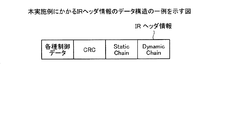
図2は、本実施例にかかるIRヘッダ情報のデータ構造の一例を示す図である。同図に示すように、このIRヘッダ情報は、各種制御データと、CRC(Cyclic Redundancy Check)と、Static Chainと、Dynamic Chainとを有する。このうち、Static Chainは、サービス開始から変更されないヘッダ部分の情報(例えば、IPアドレスなど)である。また、Dynamic Chainは、時間と共に変更されるヘッダ部分の情報(例えば、RTPヘッダに含まれるタイムスタンプ)である。 FIG. 2 is a diagram illustrating an example of a data structure of IR header information according to the present embodiment. As shown in the figure, this IR header information includes various control data, CRC (Cyclic Redundancy Check), Static Chain, and Dynamic Chain. Among these, Static Chain is information (for example, IP address) of the header part that is not changed from the start of the service. The dynamic chain is information of a header part that changes with time (for example, a time stamp included in the RTP header).
図3は、本実施例にかかるFOヘッダ情報のデータ構造の一例を示す図である。同図に示すように、このFOヘッダ情報は、各種制御データと、CRCと、Dynamic Chainとを有する。図4は、本実施例にかかるSOヘッダ情報のデータ構造の一例を示す図である。同図に示すように、このSOヘッダ情報は、各種制御データと、CRCと、付加情報となるExtensionとを有する。 FIG. 3 is a diagram illustrating an example of the data structure of the FO header information according to the present embodiment. As shown in the figure, this FO header information includes various control data, CRC, and dynamic chain. FIG. 4 is a diagram illustrating an example of the data structure of the SO header information according to the present embodiment. As shown in the figure, the SO header information includes various control data, a CRC, and an extension as additional information.
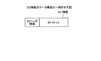
ところで、基地局100は、専用のチャネル(例えば、MTCH<Multicast Traffic Channel>)を経由して、データ制御部がコンテンツと最大圧縮状態のヘッダの情報とを対応付けたSO情報を生成し、生成したSO情報を各端末装置200,300に送信する。このSO情報は、ヘッダ制御部から送信されるヘッダの情報とは別に、各端末装置200,300に送信される。図5は、SO情報のデータ構造の一例を示す図である。同図に示すように、このSO情報には、SOヘッダ情報(図4参照)と、コンテンツを格納するIPパケットを有している。
By the way, in the
端末装置200,300は、自装置と対応付けられたヘッダ制御部から受信したIRヘッダ情報、FOヘッダ情報、SOヘッダ情報を利用して、SO情報に含まれるSOヘッダ情報を伸長する(Static ChainおよびDynamic Chainを生成する)ことにより、基地局100から受信したコンテンツを再生する。
The
ここで、SOヘッダ情報を伸長する手法は、従来のROHCに準拠する。すなわち、Static Chainは、IRヘッダ情報に含まれるStatic Chainをそのまま利用する。また、Dynamic Chainは、IRヘッダ情報およびFOヘッダ情報に含まれるDynamic Chainから推定したDynamic Chainを利用する。例えば、FOヘッダ情報のDynamic Chainに含まれるタイムスタンプが、1,2,3となっていれば、次に受信するDynamic Chainのタイムスタンプは、4と推定することができる。 Here, the method for expanding the SO header information is based on the conventional ROHC. That is, the Static Chain uses the Static Chain included in the IR header information as it is. The Dynamic Chain uses a Dynamic Chain estimated from the Dynamic Chain included in the IR header information and the FO header information. For example, if the time stamps included in the dynamic chain of the FO header information are 1, 2, and 3, the time stamp of the next dynamic chain to be received can be estimated to be 4.
このように、本実施例にかかるMBMSシステム50は、基地局100が、各端末装置200,300に対応するヘッダ制御部を用いて、各端末装置200,300と同期を行い、ヘッダ制御部がヘッダの情報のみを端末装置に送信し、データ制御部がSO情報を端末装置に送信する。そして、端末装置200,300がSO情報に含まれるSOヘッダ情報を伸長して、コンテンツを再生するので、MBMSにROCHの技術を適用することができ、スループットを向上させることができる。
Thus, in the MBMS system 50 according to the present embodiment, the
次に、図1に示した基地局100の構成について説明する。図6は、本実施例にかかる基地局100の構成を示す機能ブロック図である。同図に示すように、この基地局100は、上位MBMS用アプリケーション110と、無線通信部120と、RRM(Radio Resource Management)制御部130と、MBMS機能モジュール140とを有する。
Next, the configuration of
このうち、上位MBMS用アプリケーション110は、端末装置200または端末装置300からMBMSのサービス要求を取得した場合に、マルチコンテンツの情報をMBMS機能モジュール140に出力する手段である。上位MBMS用アプリケーション110が出力するマルチコンテンツの情報は、各ストリーミングサーバ(図示略)から基地局100に転送されてきたデータとなる。無線通信部120は、端末装置200,300(あるいはその他の)との間における無線データ通信を行う手段である。
Among them, the
RRM制御部130は、端末装置200,300からMBMSのサービス要求を取得した場合に、MBMSサービス要求に応答すると共に、データ制御タスク160と、サービス要求を受け付けた端末装置に対応するヘッダ制御タスクとをMBMS機能モジュール140中に生成する手段である。
When the
一例として、RRM制御部130は、端末装置200からMBMSのサービス要求を取得した場合には、端末装置200に対応する第1ヘッダ制御タスク170aを生成する。また、RRM制御部130は、端末装置300からMBMSのサービス要求を取得した場合には、第2ヘッダ制御タスク170bを生成する。
As an example, when the
また、RRM制御部130は、端末装置からMBMSのサービス要求を取得した場合には、サービス要求元の端末装置に対して、MBMS専用のUL(Uplink)/DL(Downlink)ベアラの生成要求を行う。このUL/DLベアラは、ヘッダの圧縮がCompressor(基地局100のヘッダ制御タスク)/Decompressor(端末装置のヘッダ制御タスク)ともに高圧縮モードに移行するまでの制御用チャネルである。
Further, when the
MBMS機能モジュール140は、ヘッダコンテクストDB150と、データ制御タスク160と、第1ヘッダ制御タスク170aと、第2ヘッダ制御タスク170bとを有する。なお、ここでは一例として、第1、2ヘッダ制御タスク170a、170bを示すが、このヘッダ制御タスクは、コンテンツの送信先となる端末装置の数だけ存在する。すなわち、コンテンツの送信先となる端末装置がn(nは1以上の数)個存在する場合には、ヘッダ制御タスクは、n個存在する。
The
ヘッダコンテクストDB150は、MBMSのサービス提供先となる端末装置の各種情報を記憶する記憶手段である。具体的に、このヘッダコンテクストDB150は、サービス提供先となる端末装置のStatic Chainおよび、Dynamic Chain等の情報を記憶している。
The
データ制御タスク160は、MBMSのサービス要求元となる複数の端末装置に対して、コンテンツ(SO情報;図5参照)を送信する手段であり、MBMSデータ受信部161と、ヘッダ生成部162と、データ転送機能部163とを有する。
The data control
MBMSデータ受信部161は、上位MBMS用アプリケーション110からコンテンツを受信し、受信したコンテンツをデータ転送機能部163に出力する手段である。ヘッダ生成部162は、サービス提供先となる端末装置のヘッダ(SOヘッダ情報)を生成し、生成したSOヘッダ情報をデータ転送機能部163に出力する手段である。
The MBMS
ヘッダ生成部162は、ヘッダコンテクストDB150を参照して、サービス提供先となる端末装置のStatic Chainおよび、Dynamic Chain等を取得し、取得した情報に基づいて、SOヘッダ情報を生成する。ヘッダ生成部162が、SOヘッダ情報を生成する手法は、従来のROCHに準拠する。
The
また、ヘッダ生成部162は、RRM制御部130に生成された場合に、サービス提供先となる端末装置のヘッダ情報の全て(Static Chain、Dynamic Chain等、RFC<Request For Comment>に準拠する情報)を第1ヘッダ制御タスク170a(第2ヘッダ制御タスク170b)に出力する。
Further, the
ヘッダ制御タスク(第1ヘッダ制御タスク170a、第2ヘッダ制御タスク170b)は、対応付けられた端末装置との間で圧縮状態を同期することにより、端末装置に送信するヘッダの圧縮状態を判定し、判定結果に基づいてヘッダを圧縮する手段である。ヘッダ制御タスクは、圧縮したヘッダの情報を、データ制御タスク160がSO情報を送信するチャネル(MTCH)とは別のチャネル(DCCH)を経由して、端末装置に送信する。
The header control tasks (the first
ここでは、ヘッダ制御タスクの説明として、第1ヘッダ制御タスク170aを用いて説明する。第2ヘッダ制御タスク170bの説明は、対応付けられた端末装置が第1ヘッダ制御タスク170aと異なるだけなので説明を省略する。
Here, as a description of the header control task, description will be given using the first
第1ヘッダ制御タスク170aは、ヘッダ判定機能部171と、Compressor機能部172と、FSM(シーケンサー)173とを有する。ヘッダ判定機能部171は、端末装置200との間でフィードバックパケットを受信することにより圧縮状態を同期し、圧縮状態に応じて、IRヘッダ情報、FOヘッダ情報あるいはSOヘッダ情報を端末装置200に送信する手段である。
The first
ヘッダ判定機能部171は、MBMSのサービス開始時に、Compressor機能部172に対してFSM173の生成要求を行う。そして、ヘッダ判定機能部171は、端末装置200から受信するフィードバックパケットに基づいて、FSM173の状態を遷移させる(Compressor機能部172を介して、FSM173の状態を遷移させる)。
The header
ヘッダ判定機能部171は、FSM173の状態が、IR stateの場合には、IRヘッダ情報を生成する。そして、ヘッダ判定機能部171は、DCCHを経由して、IRヘッダ情報を端末装置200に送信する。なお、ヘッダ判定機能部171は、随時変更するDynamic Chainの情報をヘッダコンテクストDB150に登録する。
The header
ヘッダ判定機能部171は、IRヘッダ情報を端末装置200に送信した後に、端末装置200からフィードバックパケット(ACK<ACKnowledgement>)を受信した場合には、FSM173の状態をIR stateからFO stateに遷移させる。あるいは、ヘッダ判定機能部171は、FSM173の状態をIR stateに設定してから、所定時間経過した後に、FSMの状態をFO stateに遷移させる。
When the header
ヘッダ判定機能部171は、FSM173の状態が、FO stateの場合には、FOヘッダ情報を生成する。そして、ヘッダ判定機能部171は、DCCHを経由して、FOヘッダ情報を端末装置200に送信する。
The header
ヘッダ判定機能部171は、FOヘッダ情報を端末装置200に送信した後に、端末装置200からフィードバックパケット(ACK<ACKnowledgement>)を受信した場合には、FSM173の状態をFO stateからSO stateに遷移させる。あるいは、ヘッダ判定機能部171は、FSM173の状態をFO stateに設定してから、所定時間経過した後に、FSM173の状態をSO stateに遷移させる。
When the header
ヘッダ判定機能部171は、FSM173の状態が、SO stateの場合には、SOヘッダ情報を生成する。そして、ヘッダ判定機能部171は、DCCHを経由して、SOヘッダ情報を端末装置200に送信する。
The header
なお、ヘッダ判定機能部171は、FSM173の状態が、SO stateの状態で、端末装置200にエラーが発生し、端末装置200からフィードバックパケット(NACK<Negative Acknowledgment>)を受信した場合には、FSM173の状態をFO stateに遷移させる。
The header
また、ヘッダ判定機能部171は、FSM173の状態が、FO stateの状態で、端末装置200にエラーが発生し、端末装置200からフィードバックパケット(NACK<Negative Acknowledgment>)を受信した場合には、FSM173の状態をIR stateに遷移させる。
In addition, when the
Compressor機能部172は、FSM173を生成すると共に、ヘッダ判定機能部171から入力される制御命令に応じて、FSM173の状態を遷移させる手段である。FSM173は、第1ヘッダ制御タスク170aと端末装置との間で同期する圧縮状態を管理するための手段である。FSM173の初期状態は、IR stateとなり、Compressor機能部172に制御させることでFO state、SO stateに遷移する。
The
ここで、図6に示した基地局100の処理シーケンスを説明する。図7は、本実施例にかかる基地局100の処理シーケンスを示す図である。基地局100は、RRM制御部130が、端末装置200からMBMS要求を取得した場合には、端末装置200にMBMS要求に対する応答を行う(図7の(1)参照)。
Here, the processing sequence of the
RRM制御部130は、MBMSベアラの生成要求を上位MBMS用アプリケーション110に出力し、上位MBMS用アプリケーション110から応答を取得する(図7の(2)参照)。続いて、RRM制御部130は、ベアラの生成(UL/DL)要求を端末装置200に送信し、端末装置200からの応答を取得し(図7の(3)参照)、データ制御タスク160、第1ヘッダ制御タスク170aを生成する(図7の(4)、(5)参照)。
The
ヘッダ生成部162は、ヘッダ判定機能部171にヘッダ情報の全てを通知し(図7の(6)参照)、ヘッダ判定機能部171が、Compressor機能部172に対して、FSM173の生成要求を行い(図7の(7)参照)、Compressor機能部172が、FSM173を生成する(図7の(8)参照)。
The
続いて、ヘッダ判定機能部171は、端末装置200に対してIRヘッダ情報を送信し(図7の(9)参照)、端末装置200からフィードバックパケット(ACK)を受信する(図7の(10)参照)。
Subsequently, the header
ヘッダ判定機能部171は、ACK受信確認を行った後に(図7の(11)参照)、FSM173の遷移要求をCompressor機能部172に出力し(図7の(12)参照)、Compressor機能部172がFSM173の状態をIR stateからFO stateに遷移させる(図7の(13)参照)。
After performing the ACK reception confirmation (see (11) in FIG. 7), the header
ヘッダ判定機能部171は、FSM173の状態がFO stateに遷移した場合に、FOヘッダ情報を端末装置200に送信する(図7の(14−1)参照)。なお、FOヘッダ情報が端末装置200に送信された後に、データ転送機能部163は、SO情報を各端末装置にSO情報を出力する(図7の(14−2)参照)。
When the state of the
ヘッダ判定機能部171は、端末装置200からフィードバックパケット(ACK)を受信し(図7の(15)参照)、ACK受信確認を行った後に(図7の(16)参照)、FSM173の遷移要求をCompressor機能部172に出力する(図7の(17)参照)。
The header
Compressor機能部172は、FSM173の状態をFO stateからSO stateに遷移させ(図7の(18)参照)、ヘッダ判定機能部171は、SOヘッダ情報を端末装置200に送信する。
The
次に、図1に示した端末装置200の構成について説明する(端末装置300の構成は、端末装置200の構成と同様であるため説明を省略する)。図8は、本実施例にかかる端末装置200の構成を示す機能ブロック図である。同図に示すように、この端末装置200は、上位MBMS用アプリケーション210と、無線通信部220と、RRC制御部230と、MBMS機能モジュール240とを有する。
Next, the configuration of the
このうち、上位MBMS用アプリケーション210は、入力装置(図示略)を介してユーザからコンテンツの配信要求を取得した場合に、RRC制御部230にMBMSベアラの生成要求を出力する手段である。また、上位MBMS用アプリケーション210は、データ制御タスク260からコンテンツを取得した場合には、ディスプレイ、スピーカ等(図示略)にコンテンツを出力する。無線通信部220は、基地局100等との間における無線データ通信を実行する手段である。
Among them, the
RRC制御部230は、基地局100にMBMSの開始要求を行った場合に、MBMS機能モジュール240中に、データ制御タスク260およびヘッダ制御タスク270を生成する手段である。
The
MBMS機能モジュール240は、ヘッダコンテクストDB250と、データ制御タスク260と、ヘッダ制御タスク270とを有する。このうち、ヘッダコンテクストDB250は、基地局100から送信される、IRヘッダ情報、FOヘッダ情報のStatic Chainおよび、Dynamic Chain等の情報を記憶する記憶手段である。
The
データ制御タスク260は、基地局100からMTCHを経由して送信されるSO情報を受信し、ヘッダ制御タスク270からの受信許可および圧縮コンテキスト情報を基に、SO情報に含まれるヘッダを伸長する手段である。データ制御タスク260は、MBMSデータ転送部261と、ヘッダチェック部262と、データ分離機能部263とを有する。
The data control
MBMSデータ転送部261は、伸長したヘッダの情報とコンテンツの情報とを対応付けて上位MBMS用アプリケーション210に出力する手段である。ヘッダチェック部262は、データ分離機能によって伸長されたヘッダのエラー(CRCエラー、SN番号不一致等)を検出する手段である。ヘッダチェック部262は、エラーを検出した場合に、エラーを検出した旨の情報を、ヘッダ判定機能部271に出力する。
The MBMS
データ分離機能部263は、ヘッダ制御タスク270から受信許可を取得した場合に、MTCHを経由してSO情報を受信し、SO情報に含まれるSOヘッダ情報を伸長する手段である。データ分離機能部263が、SOヘッダ情報を伸長する場合には、ヘッダコンテクストDB250を参照し、SOヘッダ情報にStatic Chainを付加すると共に、Dynamic Chainを推定し、推定したDynamic ChainをSOヘッダ情報に付加する。データ分離機能部263は、伸長したヘッダの情報とコンテンツ情報とを対応付けてMBMSデータ転送部261に出力する。
The data
ヘッダ制御タスク270は、ROHCに準拠するFSM280を用意し、高圧縮状態となったヘッダを伸長できるまでFSM280を制御する手段である。また、ヘッダ制御タスク270は、ヘッダチェック部262からヘッダのエラーを検出した旨の情報を取得した場合には、再度、FSM280の状態を制御しなおす。ヘッダ制御タスク270は、ヘッダ判定機能部271と、Decompressor機能部272とを有する。
The
ヘッダ判定機能部271は、MBMSのサービス開始時に、DeCompressor機能部272に対してFSM280の生成要求を行う。そして、ヘッダ判定機能部271は、基地局100から送信されるパケット(IRヘッダ情報、FOヘッダ情報、SOヘッダ情報)に対応して、フィードバックパケットを返信することにより、基地局100との間で圧縮状態を同期する。
The header
ヘッダ判定機能部271は、DCCHを経由して、IRヘッダ情報を取得した場合に(所定回数取得した場合に)、フィードバックパケットを基地局100に出力する。その後、ヘッダ判定機能部271がFOヘッダ情報を受信した場合には、FSM280の状態を、No contextからFull contextに遷移させる(Static contextに遷移させても良い)。
The header
ヘッダ判定機能部271は、FSM280の状態をFull contextに遷移させた後(あるいは、Static contextに遷移させた後)に、フィードバックパケットを基地局100に送信し、データ分離機能部263に対して、受信許可を出力する。なお、ヘッダ判定機能部271は、基地局100から送信されるIRヘッダ情報、FOヘッダ情報、SOヘッダ情報を、ヘッダコンテクストDB250に登録する。
The header
Decompressor機能部272は、FSM280を生成すると共に、ヘッダ判定機能部271から入力される制御命令に応じて、FSM280の状態を遷移させる手段である。FSM280は、ヘッダ制御タスク270と端末装置との間で同期する圧縮情報を管理するための手段である。FSM280の初期状態は、No contextとなり、Decompressor機能部272に制御されることでStatic context、Full contextに遷移する。
The
ここで、図8に示した端末装置200の処理シーケンスを説明する。図9は、本実施例にかかる端末装置200の処理シーケンスを示す図であり、図10は、圧縮されたヘッダを伸長する際にエラーを検出した場合の端末装置200の処理シーケンスを示す図である。
Here, a processing sequence of the
端末装置200は、RRC制御部230が上位MBMS用アプリケーション210からMBMSベアラ生成要求を取得し(図9の(1)参照)、RRC制御230がMBMS開始要求を基地局100に送信し、基地局100からの応答を受信する(図9の(2)参照)。また、ベアラ生成(UL/DL)要求を基地局100から取得した場合には、基地局100に応答を行う(図9の(3)参照)。
In the
RRC制御部230は、データ制御タスク260およびヘッダ制御タスク270を生成し(図9の(4)参照)、Decompressor機能部272が、FSM280を生成する(図9の(5)参照)。
The
ヘッダ判定機能部271は、IRヘッダ情報を受信し(図9の(6)参照)、IR受信確認を行い(図9の(7)参照)、フィードバックパケット(ACK)を基地局100に送信する(図9の(8)参照)。ヘッダ判定機能部271は、IRヘッダ情報を受信し、IRヘッダ情報に含まれるStatic Chainと、Dynamic Chainを順次、ヘッダコンテクストDB250に登録し、ヘッダコンテクストDB250に登録された情報に基づいて、SOヘッダ情報が確実に伸長できることが確認できた場合に、フィードバックパケット(ACK)を基地局100に送信する。
The header
ヘッダ判定機能部271は、FOヘッダ情報を基地局100から受信し(図9の(9)参照)、FSM280の遷移要求をDecompressor機能部272に出力し(図9の(10)参照)、Decompressor機能部272が、FSM280の状態をNo contextからFull Contextに遷移させる(図9の(11)参照)。
The header
そして、ヘッダ判定機能部271は、フィードバックパケット(ACK)を基地局100に送信し(図9の(12)参照)、受信許可をデータ分離機能部263に出力する(図9の(13)参照)。データ分離機能部263は、受信許可を取得した後に、MTCHを経由して送信されるSO情報を受信する(図9の(14)参照)。
Then, the header
次に、圧縮されたヘッダを伸長する際にエラーを検出した場合の端末装置200の処理について説明する。図10に示すように、ヘッダチェック部262は、SO情報のエラー(CRCエラー、SN番号の不一致)を検出した場合に、ヘッダ判定機能部271にエラー通知を行う(図10の(1)参照)。
Next, processing of the
ヘッダ判定機能部271は、FSM280の遷移要求をDecompressor機能部272に出力し(図10の(2)参照)、Decompressor機能部272は、FSM280の状態をFull contextからStatic contextに遷移させる(図10の(3)参照)。
The header
ヘッダ判定機能部271は、切断要求をデータ分離機能部263に出力し(図10の(4)参照)、フィードバックパケット(NACK)を基地局100に送信し(図10の(5)参照)、FOヘッダ情報を基地局100から受信する(図10の(6)参照)。
The header
ヘッダ判定機能部271は、FO受信確認を行い(図10の(7)参照)、フィードバックパケット(ACK)を基地局100に送信する(図10の(8)参照)。ヘッダ判定機能部271は、FOヘッダ情報を受信し、FOヘッダ情報に含まれるDynamic Chainを順次、ヘッダコンテクストDB250に登録し、ヘッダコンテクストDB250に登録された情報に基づいて、SOヘッダ情報が確実に伸長できることが確認できた場合に、フィードバックパケット(ACK)を基地局100に送信する。
The header
ヘッダ判定機能部271は、FSM280の遷移要求をDecompressor機能部272に出力し(図10の(9)参照)、Decompressor機能部272は、FSM280の状態をStatic contextからFull contextに遷移させる(図10の(10)参照)。
The header
ヘッダ判定機能部271は、データ分離機能部263に対して受信許可を出力し(図10の(11)参照)、データ分離機能部263は、中断していたSO情報の受信を再開する。
The header
次に、本実施例にかかるMBMSシステムの処理手順について説明する。図11および図12は、本実施例にかかるMBMSシステムの処理手順を示すシーケンス図である。同図に示すように、端末装置300と基地局100との間でCamp ONし(無線系のアクセスを完了させ)(ステップS101)、端末装置200と基地局100との間でCamp ONする(ステップS102)。
Next, the processing procedure of the MBMS system according to the present embodiment will be described. 11 and 12 are sequence diagrams illustrating the processing procedure of the MBMS system according to the present embodiment. As shown in the figure, Camp ON is performed between the
端末装置200は、基地局100にMBMSサービス要求を行い(ステップS103)、基地局100が端末装置200にMBMSサービス応答を行う(ステップS104)。続いて、基地局100が端末装置200にFeedbackベアラ生成要求を行い(ステップS105)、端末装置200が基地局100にFeedbackベアラ生成応答を行う(ステップS106)。
The
端末装置200は、自身のFSMの状態をNo context状態に設定し、基地局100は、端末装置200に対応するFSMの状態をIR stateに設定し(ステップS107)、基地局100が端末装置200にIRヘッダ情報を送信する(ステップS108)。
The
端末装置200は、IRヘッダ情報を所定回数(例えば、4回)受信した後に(ステップS109)、Feedbackパケット(ACK)を基地局100に送信し(ステップS110)、基地局100は、端末装置200に対応するFSMの状態をFO stateに遷移させる(ステップS111)。
After receiving IR header information a predetermined number of times (for example, 4 times) (step S109), the
基地局100は、FOヘッダ情報を端末装置200に送信し(ステップS112)、端末装置200は、Feedbackパケット(ACK)を基地局100に送信し(ステップS113)、端末装置200は、自身のFSMの状態をFull context状態に遷移させ、基地局100は、端末装置200に対応するFSMの状態をSO stateに遷移させる(ステップS114)。
The
基地局100は、端末装置200に対して、MTCHによるSO情報の送信を継続し(ステップS115)、端末装置200は、SO情報の受信を継続する(ステップS116)。
一方、端末装置300は、基地局100にMBMSサービス要求を行い(ステップS117)、基地局100が端末装置300にMBMSサービス応答を行う(ステップS118)。また、基地局100が端末装置300にFeedbackベアラ生成要求を行い(ステップS119)、端末装置300が基地局100にFeedbackベアラ生成応答を行う(ステップS120)。
On the other hand, the
端末装置300は、自身のFSMの状態をNo context状態に設定し、基地局100は、端末装置300に対応するFSMの状態をIR stateに設定し(ステップS121)、基地局100が端末装置300にIRヘッダ情報を送信する(ステップS122)。
The
端末装置300は、IRヘッダ情報を所定回数(例えば、4回)受信した後に(ステップS123)、Feedbackパケット(ACK)を基地局100に送信し(ステップS124)、基地局100は、端末装置300に対応するFSMの状態をFO Stateに遷移させる(ステップS125)。
After receiving the IR header information a predetermined number of times (for example, 4 times) (step S123), the
基地局100は、FOヘッダ情報を端末装置300に送信し(ステップS126)、端末装置300は、Feedbackパケット(ACK)を基地局100に送信し(ステップS127)、端末装置300は、自身のFSMの状態をFull context状態に遷移させ、基地局100は、端末装置300に対応するFSMの状態をSO stateに遷移させる(ステップS128)。
The
基地局100は、端末装置300に対して、MTCHによるSO情報の送信を継続し、端末装置300は、SO情報の受信を継続して実行する(ステップS129)。
The
このように、本実施例にかかるMBMSシステムは、基地局100が端末装置200,300に対応するFSMを生成し、各FSMを利用して各端末装置との間で同期を行い、各種のパケットを端末装置に送信するのでコンテンツ配信にかかるスループットを向上させることが出来る。
As described above, in the MBMS system according to the present embodiment, the
上述してきたように、本実施例にかかるMBMSシステムは、基地局100が、MBMS機能モジュール140に、データ制御タスク160と、各端末装置200,300に対応する第1ヘッダ制御タスク170a、第2ヘッダ制御タスク170bとを生成する。そして、各ヘッダ制御タスク170a、170bが、対応付けられた端末装置200,300と圧縮状態の同期を行い、ヘッダの情報のみを端末装置200,300に送信すると共に、データ制御タスク160が、ヘッダの情報とは別に、コンテンツの情報を端末装置200,300に配信するので、MBMSにROHCの技術を適用することを可能とし、コンテンツ配信にかかるスループットを向上させることが出来る。
As described above, in the MBMS system according to the present embodiment, the
また、本実施例にかかるMBMSシステムは、端末装置200(基地局300)が、基地局の第1ヘッダ制御タスク170aと圧縮状態を同期し、ヘッダの情報を受信すると共に、受信したヘッダの情報に基づいて、MTCHを経由して送信されるSO情報のヘッダを伸長し、コンテンツを再生可能とするので、MBMSにROHCの技術を適用することを可能とする。
In the MBMS system according to the present embodiment, the terminal device 200 (base station 300) synchronizes the compression state with the first
ところで、本実施例において説明した各処理のうち、自動的に行われるものとして説明した処理の全部または一部を手動的に行うこともでき、あるいは、手動的に行われるものとして説明した処理の全部あるいは一部を公知の方法で自動的に行うこともできる。この他、上記文書中や図面中で示した処理手順、制御手順、具体的名称、各種のデータやパラメータを含む情報については、特記する場合を除いて任意に変更することができる。 By the way, among the processes described in the present embodiment, all or a part of the processes described as being automatically performed can be manually performed, or the processes described as being performed manually can be performed. All or a part can be automatically performed by a known method. In addition, the processing procedure, control procedure, specific name, and information including various data and parameters shown in the above-described document and drawings can be arbitrarily changed unless otherwise specified.
また、図6に示した基地局100、図8に示した端末装置200の各構成要素は機能概念的なものであり、必ずしも物理的に図示の如く構成されていることを要しない。すなわち、各装置の分散・統合の具体的形態は図示のものに限られず、その全部または一部を、各種の負荷や使用状況などに応じて、任意の単位で機能的または物理的に分散・統合して構成することができる。さらに、各装置にて行われる各処理機能は、その全部または任意の一部がCPUおよび当該CPUにて解析実行されるプログラムにて実現され、あるいは、ワイヤードロジックによるハードウェアとして実現され得る。
Further, each component of the
図13は、本実施例に示した基地局100を構成するコンピュータ400のハードウェア構成を示す図(一例)であり、図14は、本実施例に示した端末装置200を構成するコンピュータ500のハードウェア構成を示す図(一例)である。なお、端末装置300に対応するハードウェア構成図は、端末装置200と同様である。
FIG. 13 is a diagram (one example) showing a hardware configuration of a
同図に示すように、このコンピュータ(基地局)400は、入力装置410と、ディスプレイ420と、端末装置200,300等との間で無線通信を実行する無線通信装置430と、CPU440と、メモリ450とをバス460で接続している。なお、その他の構成は、周知の基地局の構成と同様であるため説明を省略する。
As shown in the figure, the computer (base station) 400 includes an
CPU440が、メモリ450に記憶されたRRM制御プログラム450aを読み出して実行することにより、RRM制御タスク440aが起動される。ここで、RRM制御タスク440aは、図6に示したRRM制御部130に対応する。
When the
そして、RRM制御タスク440aは、端末装置200,300にサービスを開始する場合に、データ制御タスク440bおよびヘッダ制御タスク440cを生成することにより、各端末装置との圧縮状態を同期すると共に、ヘッダの情報、コンテンツを配信する。ここで、データ制御タスク440bおよびヘッダ制御タスク440cは、図6に示したデータ制御タスク160、第1,2ヘッダ制御タスク170a,170bに対応する。
The
続いて、図14に示すように、このコンピュータ(端末装置)500は、入力装置510と、ディスプレイ520と、基地局100等との間で無線通信を実行する無線通信装置530と、ユーザからのMBMS要求を受け付けるアプリケーションプロセッサ540と、CPU550と、メモリ560とをバス570で接続している。なお、その他の構成は、周知の端末装置の構成と同様であるため説明を省略する。
Next, as shown in FIG. 14, the computer (terminal device) 500 includes an
CPU550が、メモリ560に記憶されたRRC制御プログラム560aを読み出して実行することにより、RRC制御タスク550aが起動される。ここでRRC制御タスク550aは、図8に示したデータ制御タスク260に対応する。
When the
そして、RRC制御タスク550aは、基地局100からサービス提供を受ける場合に、データ制御タスク550bおよびヘッダ制御タスク550cを生成することにより、基地局100との圧縮状態を同期すると共に、ヘッダの情報、コンテンツの配信を受け付け、圧縮されたヘッダを伸長してコンテンツを再生する。
Then, when receiving the service provision from the
ところで、図13に示したRRM制御プログラム450a、図14に示したRRC制御プログラム560aは、必ずしも最初からメモリ450,560に記憶させておく必要はない。たとえば、コンピュータに挿入されるフレキシブルディスク(FD)、CD−ROM、DVDディスク、光磁気ディスク、ICカードなどの「可搬用の物理媒体」、または、コンピュータの内外に備えられるハードディスクドライブ(HDD)などの「固定用の物理媒体」、さらには、公衆回線、インターネット、LAN、WANなどを介してコンピュータに接続される「他のコンピュータ(またはサーバ)」などにRRM制御プログラム450a、RRC制御プログラム560aを記憶しておき、コンピュータがこれらからRRM制御プログラム450a、RRC制御プログラム560aを読み出して実行するようにしてもよい。
Incidentally, the
以上の実施例を含む実施形態に関し、更に以下の付記を開示する。 The following additional notes are further disclosed with respect to the embodiment including the above examples.
(付記1)複数の端末装置と、前記複数の端末装置にコンテンツを配信するコンテンツ配信装置とを有するコンテンツ配信システムであって、
前記コンテンツ配信装置は、
コンテンツの配信対象となる複数の端末装置に対応付けられた複数のヘッダ制御手段と、
高圧縮状態に圧縮したヘッダの情報と前記コンテンツとを対応付けたコンテンツ情報を前記複数の端末装置に配信するコンテンツ配信手段とを備え、
前記ヘッダ制御手段は、対応付けられた端末装置との間で圧縮状態を同期することにより、前記端末装置に送信するヘッダの圧縮状態を判定する判定手段と、
前記判定手段の判定結果に基づいてヘッダを圧縮し、圧縮したヘッダの情報となるヘッダ圧縮情報を、前記コンテンツ情報とは別に、前記ヘッダ制御手段に対応付けられた端末装置に配信するヘッダ配信手段とを有する
ことを特徴とするコンテンツ配信システム。
(Appendix 1) A content distribution system having a plurality of terminal devices and a content distribution device for distributing content to the plurality of terminal devices,
The content distribution device includes:
A plurality of header control means associated with a plurality of terminal devices to which content is to be distributed;
Content distribution means for distributing content information in which the content of the header compressed in a highly compressed state is associated with the content to the plurality of terminal devices;
The header control means determines the compression state of the header to be transmitted to the terminal device by synchronizing the compression state with the associated terminal device, and
A header distribution unit that compresses a header based on a determination result of the determination unit and distributes compressed header information, which is compressed header information, to a terminal device associated with the header control unit, separately from the content information A content distribution system characterized by comprising:
(付記2)前記端末装置は、前記コンテンツ情報と前記ヘッダ圧縮情報とを受信した場合に、前記コンテンツ情報に含まれる高圧縮状態に圧縮されたヘッダの情報を前記ヘッダ圧縮情報に基づいて伸長する伸長手段を含んでいることを特徴とする付記1に記載のコンテンツ配信システム。
(Supplementary Note 2) When the terminal device receives the content information and the header compression information, the terminal device expands the header information compressed in a high compression state included in the content information based on the header compression information. The content distribution system according to
(付記3)前記ヘッダ配信手段は、前記判定手段の判定結果に基づいて、静的情報および動的情報を含んだ非圧縮状態、動的情報のみを含んだ最小圧縮状態、静的情報および動的情報を含まない最大圧縮状態のいずれかの状態となるように、ヘッダを圧縮することを特徴とする付記1または2に記載のコンテンツ配信システム。
(Additional remark 3) Based on the determination result of the said determination means, the said header delivery means is the uncompressed state containing static information and dynamic information, the minimum compression state containing only dynamic information, static information, and dynamic information. The content distribution system according to
(付記4)前記コンテンツ配信手段は、第1のチャネルを経由して、前記コンテンツ情報を端末装置に配信し、前記ヘッダ配信手段は、第2のチャネルを経由して、前記ヘッダ圧縮情報を、対応付けられた端末装置に配信することを特徴とする付記1、2または3に記載のコンテンツ配信システム。
(Supplementary Note 4) The content distribution means distributes the content information to a terminal device via a first channel, and the header distribution means transmits the header compression information via a second channel, 4. The content distribution system according to
(付記5)コンテンツの配信対象となる複数の端末装置に対応付けられた複数のヘッダ制御手段と、
高圧縮状態に圧縮したヘッダの情報と前記コンテンツとを対応付けたコンテンツ情報を前記複数の端末装置に配信するコンテンツ配信手段とを備え、
前記ヘッダ制御手段は、対応付けられた端末装置との間で圧縮状態を同期することにより、前記端末装置に送信するヘッダの圧縮状態を判定する判定手段と、
前記判定手段の判定結果に基づいてヘッダを圧縮し、圧縮したヘッダの情報となるヘッダ圧縮情報を、前記コンテンツ情報とは別に、前記ヘッダ制御手段に対応付けられた端末装置に配信するヘッダ配信手段とを有する
ことを特徴とするコンテンツ配信装置。
(Additional remark 5) The some header control means matched with the some terminal device used as the delivery object of a content,
Content distribution means for distributing content information in which the content of the header compressed in a highly compressed state is associated with the content to the plurality of terminal devices;
The header control means determines the compression state of the header to be transmitted to the terminal device by synchronizing the compression state with the associated terminal device, and
A header distribution unit that compresses a header based on a determination result of the determination unit and distributes compressed header information, which is compressed header information, to a terminal device associated with the header control unit, separately from the content information The content distribution apparatus characterized by having.
(付記6)前記ヘッダ配信手段は、前記判定手段の判定結果に基づいて、静的情報および動的情報を含んだ非圧縮状態、動的情報のみを含んだ最小圧縮状態、静的情報および動的情報を含まない最大圧縮状態のいずれかの状態となるように、ヘッダを圧縮することを特徴とする付記5に記載のコンテンツ配信装置。 (Additional remark 6) Based on the determination result of the said determination means, the said header delivery means is the uncompressed state containing static information and dynamic information, the minimum compression state containing only dynamic information, static information, and dynamic information. The content distribution apparatus according to appendix 5, wherein the header is compressed so as to be in one of the maximum compression states not including the target information.
(付記7)前記コンテンツ配信手段は、第1のチャネルを経由して、前記コンテンツ情報を端末装置に配信し、前記ヘッダ配信手段は、第2のチャネルを経由して、前記ヘッダ圧縮情報を、対応付けられた端末装置に配信することを特徴とする付記5または6に記載のコンテンツ配信装置。 (Supplementary note 7) The content distribution means distributes the content information to a terminal device via a first channel, and the header distribution means transmits the header compression information via a second channel, 7. The content distribution device according to appendix 5 or 6, wherein the content distribution device distributes to the associated terminal device.
(付記8)付記5、6または7のいずれか一つに記載された基地局から、コンテンツ情報とヘッダ圧縮情報とを受信した場合に、前記コンテンツ情報に含まれる高圧縮状態に圧縮されたヘッダの情報を前記ヘッダ圧縮情報に基づいて伸長する伸長手段
を備えたことを特徴とする端末装置。
(Supplementary Note 8) When the content information and the header compression information are received from the base station described in any one of Supplementary Notes 5, 6 or 7, the header compressed to the high compression state included in the content information A terminal device comprising: expansion means for expanding the information on the basis of the header compression information.
(付記9)複数の端末装置と、前記複数の端末装置にコンテンツを配信するコンテンツ配信装置とを有するコンテンツ配信システムのコンテンツ配信方法であって、
前記コンテンツ配信装置は、
コンテンツの配信対象となる複数の端末装置に対応付けられた複数のヘッダ制御タスクを生成するステップと、
高圧縮状態に圧縮したヘッダの情報と前記コンテンツとを対応付けたコンテンツ情報を前記複数の端末装置に配信するステップとを有し、
前記ヘッダ制御タスクは、対応付けられた端末装置との間で圧縮状態を同期することにより、前記端末装置に送信するヘッダの圧縮状態を判定するステップと、
判定結果に基づいてヘッダを圧縮し、圧縮したヘッダの情報となるヘッダ圧縮情報を、前記コンテンツ情報とは別に、前記ヘッダ制御タスクに対応付けられた端末装置に配信するステップとを有する
ことを特徴とするコンテンツ配信方法。
(Supplementary note 9) A content distribution method of a content distribution system comprising a plurality of terminal devices and a content distribution device for distributing content to the plurality of terminal devices,
The content distribution device includes:
Generating a plurality of header control tasks associated with a plurality of terminal devices to which content is to be distributed;
Delivering content information associating the content of the header compressed in a highly compressed state with the content to the plurality of terminal devices,
The header control task determines a compression state of a header to be transmitted to the terminal device by synchronizing a compression state with the associated terminal device;
A step of compressing a header based on a determination result, and delivering header compression information, which is compressed header information, to a terminal device associated with the header control task separately from the content information. Content delivery method.
(付記10)前記端末装置は、前記コンテンツ情報と前記ヘッダ圧縮情報とを受信するステップと、前記コンテンツ情報に含まれる高圧縮状態に圧縮されたヘッダの情報を前記ヘッダ圧縮情報に基づいて伸長するステップとを有することを特徴とする付記9に記載のコンテンツ配信方法。 (Supplementary Note 10) The terminal device receives the content information and the header compression information, and decompresses the information of the header compressed in the high compression state included in the content information based on the header compression information. The content delivery method according to claim 9, further comprising steps.
(付記11)前記コンテンツ配信装置は、ヘッダの圧縮状態に対する判定結果に基づいて、静的情報および動的情報を含んだ非圧縮状態、動的情報のみを含んだ最小圧縮状態、静的情報および動的情報を含まない最大圧縮状態のいずれかの状態となるように、ヘッダを圧縮することを特徴とする付記9または10に記載のコンテンツ配信方法。
(Additional remark 11) Based on the determination result with respect to the compression state of the header, the content distribution device includes an uncompressed state including static information and dynamic information, a minimum compressed state including only dynamic information, static information, and The content distribution method according to
(付記12)前記コンテンツ配信装置は、第1のチャネルを経由して、前記コンテンツ情報を端末装置に配信し、第2のチャネルを経由して、前記ヘッダ圧縮情報を、対応付けられた端末装置に配信することを特徴とする付記9、10または11に記載のコンテンツ配信方法。
(Supplementary Note 12) The content distribution device distributes the content information to a terminal device via a first channel, and associates the header compression information with the associated terminal device via a second channel. The content delivery method according to
(付記13)コンピュータに、
コンテンツの配信対象となる複数の端末装置に対応付けられた複数のヘッダ制御タスクを生成するタスク生成手順と、
高圧縮状態に圧縮したヘッダの情報と前記コンテンツとを対応付けたコンテンツ情報を前記複数の端末装置に配信するコンテンツ配信手順とを実行させ、
前記ヘッダ制御タスクは、対応付けられた端末装置との間で圧縮状態を同期することにより、前記端末装置に送信するヘッダの圧縮状態を判定する判定手順と、
前記判定手順の判定結果に基づいてヘッダを圧縮し、圧縮したヘッダの情報となるヘッダ圧縮情報を、前記コンテンツ情報とは別に、前記ヘッダ制御タスクに対応付けられた端末装置に配信するヘッダ配信手順とを
コンピュータに実行させることを特徴とするコンテンツ配信プログラム。
(Supplementary note 13)
A task generation procedure for generating a plurality of header control tasks associated with a plurality of terminal devices to which content is to be distributed;
A content delivery procedure for delivering content information in which the content of the header compressed in a highly compressed state is associated with the content to the plurality of terminal devices;
The header control task determines the compression state of the header to be transmitted to the terminal device by synchronizing the compression state with the associated terminal device, and
A header distribution procedure for compressing a header based on a determination result of the determination procedure and distributing header compression information, which is compressed header information, to a terminal device associated with the header control task separately from the content information A content distribution program for causing a computer to execute.
(付記14)前記ヘッダ配信手順は、前記判定手順の判定結果に基づいて、静的情報および動的情報を含んだ非圧縮状態、動的情報のみを含んだ最小圧縮状態、静的情報および動的情報を含まない最大圧縮状態のいずれかの状態となるように、ヘッダを圧縮することを特徴とする付記13に記載のコンテンツ配信プログラム。 (Supplementary Note 14) The header distribution procedure is based on the determination result of the determination procedure, in an uncompressed state including static information and dynamic information, a minimum compressed state including only dynamic information, static information, and dynamic information. 14. The content distribution program according to appendix 13, wherein the header is compressed so as to be in one of the maximum compression states not including the target information.
(付記15)前記コンテンツ配信手順は、第1のチャネルを経由して、前記コンテンツ情報を端末装置に配信し、前記ヘッダ配信手順は、第2のチャネルを経由して、前記ヘッダ圧縮情報を、対応付けられた端末装置に配信することを特徴とする付記13または14に記載のコンテンツ配信プログラム。
(Supplementary Note 15) The content distribution procedure distributes the content information to the terminal device via the first channel, and the header distribution procedure includes the header compression information via the second channel. 15. The content distribution program according to
10,100 基地局
20,200,300 端末装置
50 MBMSシステム
110,210 上位MBMS用アプリケーション
120,220 無線通信部
130 RRM制御部
140,240 MBMS機能モジュール
150,250 ヘッダコンテクストDB
160,260 データ制御タスク
161 MBMSデータ受信部
162 ヘッダ生成部
163 データ転送機能部
170a 第1ヘッダ制御タスク
170b 第2ヘッダ制御タスク
171,271 ヘッダ判定機能部
172 Compressor機能部
173,280 FSM
230 RRC制御部
261 MBMSデータ転送部
262 ヘッダチェック部
263 データ分離機能部
270 ヘッダ制御タスク
272 Decompressor機能部
10, 100
160, 260
230
Claims (10)
前記コンテンツ配信装置は、
コンテンツの配信対象となる複数の端末装置に対応付けられた複数のヘッダ制御手段と、
高圧縮状態に圧縮したヘッダの情報と前記コンテンツとを対応付けたコンテンツ情報を前記複数の端末装置に配信するコンテンツ配信手段とを備え、
各ヘッダ制御手段は、対応付けられた端末装置との間で圧縮状態を同期することにより、前記端末装置に送信するヘッダの個別の圧縮状態を判定する判定手段と、
前記判定手段の判定結果に基づいてヘッダを圧縮し、圧縮したヘッダの情報となるヘッダ圧縮情報を、前記コンテンツ情報とは別に、前記ヘッダ制御手段に対応付けられた端末装置に配信するヘッダ配信手段とを有する
ことを特徴とするコンテンツ配信システム。 A content distribution system having a plurality of terminal devices and a content distribution device for distributing content to the plurality of terminal devices,
The content distribution device includes:
A plurality of header control means associated with a plurality of terminal devices to which content is to be distributed;
Content distribution means for distributing content information in which the content of the header compressed in a highly compressed state is associated with the content to the plurality of terminal devices;
Each header control means determines the individual compression state of the header to be transmitted to the terminal device by synchronizing the compression state with the associated terminal device, and
A header distribution unit that compresses a header based on a determination result of the determination unit and distributes compressed header information, which is compressed header information, to a terminal device associated with the header control unit, separately from the content information A content distribution system characterized by comprising:
高圧縮状態に圧縮したヘッダの情報と前記コンテンツとを対応付けたコンテンツ情報を前記複数の端末装置に配信するコンテンツ配信手段とを備え、
各ヘッダ制御手段は、対応付けられた端末装置との間で圧縮状態を同期することにより、前記端末装置に送信するヘッダの個別の圧縮状態を判定する判定手段と、
前記判定手段の判定結果に基づいてヘッダを圧縮し、圧縮したヘッダの情報となるヘッダ圧縮情報を、前記コンテンツ情報とは別に、前記ヘッダ制御手段に対応付けられた端末装置に配信するヘッダ配信手段とを有する
ことを特徴とするコンテンツ配信装置。 A plurality of header control means associated with a plurality of terminal devices to which content is to be distributed;
Content distribution means for distributing content information in which the content of the header compressed in a highly compressed state is associated with the content to the plurality of terminal devices;
Each header control means determines the individual compression state of the header to be transmitted to the terminal device by synchronizing the compression state with the associated terminal device, and
A header distribution unit that compresses a header based on a determination result of the determination unit and distributes compressed header information, which is compressed header information, to a terminal device associated with the header control unit, separately from the content information The content distribution apparatus characterized by having.
を備えたことを特徴とする端末装置。 When content information and header compression information are received from the base station according to any one of claims 5, 6 and 7, information on a header compressed to a high compression state included in the content information is received. A terminal device comprising decompression means for decompressing based on the header compression information.
前記コンテンツ配信装置は、
コンテンツの配信対象となる複数の端末装置に対応付けられた複数のヘッダ制御タスクを生成するステップと、
高圧縮状態に圧縮したヘッダの情報と前記コンテンツとを対応付けたコンテンツ情報を前記複数の端末装置に配信するステップとを有し、
各ヘッダ制御タスクは、対応付けられた端末装置との間で圧縮状態を同期することにより、前記端末装置に送信するヘッダの個別の圧縮状態を判定するステップと、
判定結果に基づいてヘッダを圧縮し、圧縮したヘッダの情報となるヘッダ圧縮情報を、前記コンテンツ情報とは別に、前記ヘッダ制御タスクに対応付けられた端末装置に配信するステップとを有する
ことを特徴とするコンテンツ配信方法。 A content distribution method of a content distribution system comprising a plurality of terminal devices and a content distribution device for distributing content to the plurality of terminal devices,
The content distribution device includes:
Generating a plurality of header control tasks associated with a plurality of terminal devices to which content is to be distributed;
Delivering content information associating the content of the header compressed in a highly compressed state with the content to the plurality of terminal devices,
Each header control task determines the individual compression state of the header to be transmitted to the terminal device by synchronizing the compression state with the associated terminal device;
A step of compressing a header based on a determination result, and delivering header compression information, which is compressed header information, to a terminal device associated with the header control task separately from the content information. Content delivery method.
Priority Applications (5)
| Application Number | Priority Date | Filing Date | Title |
|---|---|---|---|
| JP2008155941A JP5167971B2 (en) | 2008-06-13 | 2008-06-13 | Content distribution system, content distribution device, terminal device, and content distribution method |
| US12/369,933 US8942678B2 (en) | 2008-06-13 | 2009-02-12 | Content distributing system, content distributing apparatus, terminal device and content distributing method |
| EP20090152935 EP2134059B1 (en) | 2008-06-13 | 2009-02-16 | Content distributing system, content distributing apparatus, terminal device and content distributing method |
| KR20090019468A KR100986010B1 (en) | 2008-06-13 | 2009-03-06 | Content distributing system, content distributing apparatus, terminal device and content distributing method |
| CN2009101184656A CN101605304B (en) | 2008-06-13 | 2009-03-09 | Content distributing system, content distributing apparatus, terminal device and content distributing method |
Applications Claiming Priority (1)
| Application Number | Priority Date | Filing Date | Title |
|---|---|---|---|
| JP2008155941A JP5167971B2 (en) | 2008-06-13 | 2008-06-13 | Content distribution system, content distribution device, terminal device, and content distribution method |
Publications (2)
| Publication Number | Publication Date |
|---|---|
| JP2009302968A JP2009302968A (en) | 2009-12-24 |
| JP5167971B2 true JP5167971B2 (en) | 2013-03-21 |
Family
ID=40740194
Family Applications (1)
| Application Number | Title | Priority Date | Filing Date |
|---|---|---|---|
| JP2008155941A Expired - Fee Related JP5167971B2 (en) | 2008-06-13 | 2008-06-13 | Content distribution system, content distribution device, terminal device, and content distribution method |
Country Status (5)
| Country | Link |
|---|---|
| US (1) | US8942678B2 (en) |
| EP (1) | EP2134059B1 (en) |
| JP (1) | JP5167971B2 (en) |
| KR (1) | KR100986010B1 (en) |
| CN (1) | CN101605304B (en) |
Families Citing this family (13)
| Publication number | Priority date | Publication date | Assignee | Title |
|---|---|---|---|---|
| US9282081B2 (en) | 2005-07-28 | 2016-03-08 | Vaporstream Incorporated | Reduced traceability electronic message system and method |
| US7610345B2 (en) * | 2005-07-28 | 2009-10-27 | Vaporstream Incorporated | Reduced traceability electronic message system and method |
| JP2009206648A (en) * | 2008-02-26 | 2009-09-10 | Nec Corp | Signaling server, data communication system, and signaling processing proxy method and program |
| US20110016313A1 (en) * | 2009-07-15 | 2011-01-20 | Qualcomm Incorporated | HEADER COMPRESSION FOR TUNNELED IPsec PACKET |
| EP2567524B1 (en) * | 2010-05-03 | 2019-06-26 | Nokia Technologies Oy | Protocol overhead reduction |
| KR101772461B1 (en) | 2014-01-14 | 2017-08-30 | 엘지전자 주식회사 | Method and apparatus for transmitting/receiving broadcasting signal including robust header compression packet stream and fast information |
| US10009665B2 (en) | 2014-03-11 | 2018-06-26 | Lg Electronics Inc. | Method and device for transmitting/receiving broadcast signal |
| CN104023355B (en) * | 2014-05-15 | 2017-07-21 | 北京邮电大学 | Wireless communication network system based on centralized Control and content distribution |
| US9473979B2 (en) * | 2014-06-30 | 2016-10-18 | Motorola Solutions, Inc. | Method and system for data transmission |
| WO2018026393A1 (en) * | 2016-08-02 | 2018-02-08 | Intel IP Corporation | User equipment (ue), evolved node-b (enb) and methods for voice over lte (volte) communication in accordance with robust header compression (rohc) |
| US10951591B1 (en) * | 2016-12-20 | 2021-03-16 | Wells Fargo Bank, N.A. | SSL encryption with reduced bandwidth |
| CN110505587B (en) * | 2018-05-18 | 2021-09-14 | 成都鼎桥通信技术有限公司 | Broadband trunking communication system group establishing method and device |
| CN111092853B (en) * | 2019-10-22 | 2020-10-27 | 翱捷智能科技(上海)有限公司 | ROHC compressor and compression state adjusting method thereof |
Family Cites Families (10)
| Publication number | Priority date | Publication date | Assignee | Title |
|---|---|---|---|---|
| US6304914B1 (en) | 1998-09-22 | 2001-10-16 | Microsoft Corporation | Method and apparatus for pre-compression packaging |
| US7539130B2 (en) * | 2000-03-28 | 2009-05-26 | Nokia Corporation | Method and system for transmitting and receiving packets |
| US7031666B2 (en) | 2001-03-28 | 2006-04-18 | Qualcomm Incorporated. | Method and apparatus for header compression in a wireless communication system |
| US7031736B2 (en) | 2001-12-03 | 2006-04-18 | Nokia Corporation | Method and apparatus of header compression for broadcast services in radio telecommunication system |
| KR100936586B1 (en) * | 2002-09-19 | 2010-01-13 | 엘지전자 주식회사 | Method and system for transmitting data in multimedia broadcasting and multicast service |
| KR20040040724A (en) | 2002-11-07 | 2004-05-13 | 엘지전자 주식회사 | Up-link common channel and operation method of it in a mobile radio communication system |
| US7822067B2 (en) * | 2003-08-08 | 2010-10-26 | Qualcomm Incorporated | Header compression enhancement for broadcast/multicast services |
| KR100770857B1 (en) * | 2004-02-12 | 2007-10-26 | 삼성전자주식회사 | Method for resuming header re-compression multimedia broadcast multicast service system |
| JP2007528668A (en) * | 2004-03-09 | 2007-10-11 | トムソン ライセンシング | Secure data transmission via multi-channel permission management and control |
| EP1808995A1 (en) | 2006-01-13 | 2007-07-18 | Thomson Licensing S.A. | Method for the exchange of data packets in a network of distributed stations, device for compression of data packets and device for decompression of data packets |
-
2008
- 2008-06-13 JP JP2008155941A patent/JP5167971B2/en not_active Expired - Fee Related
-
2009
- 2009-02-12 US US12/369,933 patent/US8942678B2/en not_active Expired - Fee Related
- 2009-02-16 EP EP20090152935 patent/EP2134059B1/en not_active Ceased
- 2009-03-06 KR KR20090019468A patent/KR100986010B1/en not_active IP Right Cessation
- 2009-03-09 CN CN2009101184656A patent/CN101605304B/en not_active Expired - Fee Related
Also Published As
| Publication number | Publication date |
|---|---|
| CN101605304B (en) | 2012-02-29 |
| KR100986010B1 (en) | 2010-10-06 |
| US20090311996A1 (en) | 2009-12-17 |
| CN101605304A (en) | 2009-12-16 |
| KR20090129931A (en) | 2009-12-17 |
| JP2009302968A (en) | 2009-12-24 |
| US8942678B2 (en) | 2015-01-27 |
| EP2134059A1 (en) | 2009-12-16 |
| EP2134059B1 (en) | 2014-08-13 |
Similar Documents
| Publication | Publication Date | Title |
|---|---|---|
| JP5167971B2 (en) | Content distribution system, content distribution device, terminal device, and content distribution method | |
| KR100770857B1 (en) | Method for resuming header re-compression multimedia broadcast multicast service system | |
| JP5524125B2 (en) | Method and apparatus for overhead messaging in a wireless communication system | |
| US9288263B2 (en) | Two tier multiple sliding window mechanism for multidestination media applications | |
| JP4615828B2 (en) | Method and apparatus for band transmission of broadcast service options in a wireless communication system | |
| KR100617687B1 (en) | Method and apparatus for configurating protocol layers for multimedia broadcast/multicast service | |
| JP4087713B2 (en) | Method and apparatus for broadcast signaling in a wireless communication system | |
| EP1867135B1 (en) | Method and apparatus for enhanced file distribution in multicast or broadcast | |
| US9832745B2 (en) | Transport stream packets with time stamp generation by medium access control | |
| JP2007081883A (en) | Radio base station, and user common data transmission method | |
| US20050180383A1 (en) | Method of resuming header decompression in a multimedia broadcast/multicast service system | |
| US9883361B2 (en) | Delivering time synchronized arbitrary data in an RTP session | |
| US9425975B2 (en) | Multicast transmission using a unicast protocol | |
| KR20050100882A (en) | Method and apparatus for receiving control message using sequence numbers in multimedia broadcast/multicast service | |
| JP2017535117A (en) | Call execution method and apparatus using LTE system | |
| WO2011024272A1 (en) | Base station control apparatus and communication system | |
| CN107438991B (en) | Method and apparatus for flexible broadcast service via multimedia broadcast multicast service | |
| KR100501713B1 (en) | A Network system for transmitting packet with header compression and control method thereof | |
| JP2007300237A (en) | Transmission unit and transmission data transmitting method |
Legal Events
| Date | Code | Title | Description |
|---|---|---|---|
| A621 | Written request for application examination |
Free format text: JAPANESE INTERMEDIATE CODE: A621 Effective date: 20110315 |
|
| A977 | Report on retrieval |
Free format text: JAPANESE INTERMEDIATE CODE: A971007 Effective date: 20120828 |
|
| A131 | Notification of reasons for refusal |
Free format text: JAPANESE INTERMEDIATE CODE: A131 Effective date: 20120904 |
|
| A521 | Request for written amendment filed |
Free format text: JAPANESE INTERMEDIATE CODE: A523 Effective date: 20121102 |
|
| TRDD | Decision of grant or rejection written | ||
| A01 | Written decision to grant a patent or to grant a registration (utility model) |
Free format text: JAPANESE INTERMEDIATE CODE: A01 Effective date: 20121127 |
|
| A61 | First payment of annual fees (during grant procedure) |
Free format text: JAPANESE INTERMEDIATE CODE: A61 Effective date: 20121210 |
|
| R150 | Certificate of patent or registration of utility model |
Ref document number: 5167971 Country of ref document: JP Free format text: JAPANESE INTERMEDIATE CODE: R150 |
|
| LAPS | Cancellation because of no payment of annual fees |