JP5166692B2 - Modular transport assembly with low rear line pressure - Google Patents
Modular transport assembly with low rear line pressure Download PDFInfo
- Publication number
- JP5166692B2 JP5166692B2 JP2005319128A JP2005319128A JP5166692B2 JP 5166692 B2 JP5166692 B2 JP 5166692B2 JP 2005319128 A JP2005319128 A JP 2005319128A JP 2005319128 A JP2005319128 A JP 2005319128A JP 5166692 B2 JP5166692 B2 JP 5166692B2
- Authority
- JP
- Japan
- Prior art keywords
- roller
- belt module
- hole
- roller shaft
- modular
- Prior art date
- Legal status (The legal status is an assumption and is not a legal conclusion. Google has not performed a legal analysis and makes no representation as to the accuracy of the status listed.)
- Active
Links
- 239000002184 metal Substances 0.000 claims description 4
- 229920001971 elastomer Polymers 0.000 claims description 2
- 239000000806 elastomer Substances 0.000 claims description 2
- 239000002861 polymer material Substances 0.000 claims description 2
- 239000000463 material Substances 0.000 description 3
- 239000004033 plastic Substances 0.000 description 2
- 229920003023 plastic Polymers 0.000 description 2
- -1 polyethylene Polymers 0.000 description 2
- 239000000243 solution Substances 0.000 description 2
- 239000004677 Nylon Substances 0.000 description 1
- 239000004698 Polyethylene Substances 0.000 description 1
- 239000004743 Polypropylene Substances 0.000 description 1
- DHKHKXVYLBGOIT-UHFFFAOYSA-N acetaldehyde Diethyl Acetal Natural products CCOC(C)OCC DHKHKXVYLBGOIT-UHFFFAOYSA-N 0.000 description 1
- 125000002777 acetyl group Chemical class [H]C([H])([H])C(*)=O 0.000 description 1
- 239000012530 fluid Substances 0.000 description 1
- 230000014509 gene expression Effects 0.000 description 1
- 238000001746 injection moulding Methods 0.000 description 1
- 230000013011 mating Effects 0.000 description 1
- 238000000034 method Methods 0.000 description 1
- 238000012986 modification Methods 0.000 description 1
- 230000004048 modification Effects 0.000 description 1
- 229920001778 nylon Polymers 0.000 description 1
- 229920000573 polyethylene Polymers 0.000 description 1
- 229920000642 polymer Polymers 0.000 description 1
- 229920001155 polypropylene Polymers 0.000 description 1
- 238000011144 upstream manufacturing Methods 0.000 description 1
Images
Classifications
-
- B—PERFORMING OPERATIONS; TRANSPORTING
- B65—CONVEYING; PACKING; STORING; HANDLING THIN OR FILAMENTARY MATERIAL
- B65G—TRANSPORT OR STORAGE DEVICES, e.g. CONVEYORS FOR LOADING OR TIPPING, SHOP CONVEYOR SYSTEMS OR PNEUMATIC TUBE CONVEYORS
- B65G17/00—Conveyors having an endless traction element, e.g. a chain, transmitting movement to a continuous or substantially-continuous load-carrying surface or to a series of individual load-carriers; Endless-chain conveyors in which the chains form the load-carrying surface
- B65G17/30—Details; Auxiliary devices
- B65G17/32—Individual load-carriers
Abstract
Description
本発明はモジュール式コンベアベルト及びチェーンに関し、より詳細には、後方ラインプレッシャの低いコンベアモジュール及び該コンベアモジュールを少なくとも1つ備えるモジュール式搬送組立体に関する。 The present invention relates to a modular conveyor belt and chain, and more particularly to a conveyor module with low rear line pressure and a modular transport assembly comprising at least one conveyor module.
モジュール式ベルトやチェーンは、フレームで支えられ、製品を搬送するため駆動される相互接続されたモジュールから構成される。各モジュールは、ベルトやチェーンがフレームに沿って駆動されているときに製品を支える支持面を有する。隣り合ったモジュールは、そのモジュールから伸びるヒンジ部を通して挿入されたヒンジピンによってベルトの進行方向に相互に接続される。 Modular belts and chains are made up of interconnected modules that are supported by a frame and driven to carry the product. Each module has a support surface that supports the product when the belt or chain is driven along the frame. Adjacent modules are connected to each other in the direction of belt travel by hinge pins inserted through hinges extending from the modules.
モジュール式ベルトはコンベアの搬送方向に製品を搬送できるが、後方ラインプレッシャを抑制するために、製品を積み重ねるのは問題がある。その上、製品が積み重ねられると、摩擦の大きい製品がベルトを容易に損傷することがある。この問題に対する1つの周知の解決手段は、ヒンジピンがローラーをヒンジ部間で支持するように、モジュールを相互に接続するヒンジピンに、直に、ローラーを回転自在に取り付けることである。ローラーはヒンジピンの軸と実質的に同軸の回転軸を中心に回転する。後方ラインプレッシャを低くするため、ローラーの一部分がモジュールより上方に伸びて搬送物と係合する必要があるため、必要なローラーの口径はヒンジピンの位置とモジュールの高さによって決まる。困ったことに、このことは、モジュールの上下に広がる大口径のローラーを必要とする場合が多く、その構成は必ずしも目的とするものになるとは限らない。その上、ローラーをヒンジピンのみで支えると、ヒンジピンの不要な摩耗が生ずる場合もある。 The modular belt can transport the product in the transport direction of the conveyor, but it is problematic to stack the products in order to suppress the back line pressure. In addition, when products are stacked, high friction products can easily damage the belt. One well-known solution to this problem is to rotatably attach the roller directly to the hinge pins that interconnect the modules so that the hinge pins support the rollers between the hinge portions. The roller rotates about an axis of rotation that is substantially coaxial with the axis of the hinge pin. In order to lower the rear line pressure, a part of the roller needs to extend above the module and engage the conveyed product, so the required roller diameter depends on the position of the hinge pin and the height of the module. Unfortunately, this often requires a large diameter roller that extends up and down the module, and its configuration is not necessarily what it is intended for. Moreover, if the roller is supported only by the hinge pin, unnecessary wear of the hinge pin may occur.
後方ラインプレッシャを低減するもう一つ別の周知解決手段は、アースコットに対して特許された米国特許第4231469号に開示されている。当該明細書において、ローラーはモジュール間のローラー受け台によって支持される。そのローラーはヒンジピンの位置と無関係に搬送物と回転して接触するために、その受け台より上方に広がる。当該ローラーはベルトと搬送物間の摩擦を低減する。残念ながら、その受け台にローラーを組立てること、その受け台の中にローラーを組み込む必要があること、それから、その受け台の壁を貫通しローラー中に形成される孔を通して軸又は2本のスタブ軸を滑り込ませることは困難である。さらに、その軸は受け台の壁に形成された孔の1つから滑り落ちないように固定する必要がある。
本発明は、製品を積み重ねる際の後方ラインプレッシャを抑制するモジュール式搬送組立体を提供する。当該搬送組立体は、上面及びこの上面より上方に伸びる少なくとも1つの第1のローラー軸支持部を有する第1のベルトモジュールを備える。第1の軸支持部は孔を含む。第1のベルトモジュールに隣接する第2のベルトモジュールは、上面及びこの上面より上方に伸びる少なくとも1つの第2のローラー軸支持部を有する。第2の軸支持部は第1のローラー軸支持部に形成された孔と同軸の孔を含む。ローラー軸は第1及び第2の軸支持部の孔を通って伸びる。ベルトモジュールと搬送組立体に沿って搬送される物体の間の摩擦を低減するため、少なくとも1つのローラーがローラー軸によって回転自在に支持される。 The present invention provides a modular transport assembly that suppresses rear line pressure when stacking products. The transport assembly includes a first belt module having an upper surface and at least one first roller shaft support portion extending upward from the upper surface. The first shaft support portion includes a hole. The second belt module adjacent to the first belt module has an upper surface and at least one second roller shaft support portion extending upward from the upper surface. The second shaft support portion includes a hole coaxial with the hole formed in the first roller shaft support portion. The roller shaft extends through holes in the first and second shaft supports. At least one roller is rotatably supported by the roller shaft to reduce friction between the belt module and the object conveyed along the conveying assembly.
本発明の全般的な目的は、搬送物や組立体に深刻な損傷を与えることなく搬送物を積み重ねることのできるベルトモジュール及びそれから構成されるモジュール式搬送組立体を提供することにある。本目的はベルトモジュール本体上面より上方で回転自在に支持されるローラーを有するベルトモジュールを提供することで実現できる。 SUMMARY OF THE INVENTION The general object of the present invention is to provide a belt module and a modular transport assembly comprising the same that can stack the transported articles without seriously damaging the transported articles or the assembly. This object can be realized by providing a belt module having a roller rotatably supported above the upper surface of the belt module main body.
本発明の別の目的は、少なくともいくつかのモジュールの上面で支持される交換が容易なローラーを有する搬送組立体を提供することである。本目的は、搬送組立体からモジュールを分解せずにローラー軸の取り外しを可能とするためモジュール全体に伸びるローラー軸を提供することで実現できる。 Another object of the present invention is to provide a transport assembly having easily replaceable rollers that are supported on the upper surface of at least some modules. This object can be achieved by providing a roller shaft that extends across the entire module so that the roller shaft can be removed without disassembling the module from the transport assembly.
本発明に係る本目的及びさらに他の目的並びに効果は以下の明細書から明らかとなるであろう。以下の詳細な記載において、本発明の好ましい実施形態を添付図面を参照して説明する。これら実施形態は本発明の全範囲を示すものではなく、言うなれば、本発明は他の実施形態に用いても良い。従って、本発明の範囲を解釈するには、特許請求の範囲を参照されたい。 This and other objects and advantages of the present invention will become apparent from the following specification. In the following detailed description, preferred embodiments of the invention are described with reference to the accompanying drawings. These embodiments do not represent the full scope of the invention, that is, the invention may be used in other embodiments. Accordingly, reference should be made to the following claims for interpreting the scope of the invention.
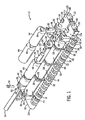
モジュール式搬送組立体、即ち、図1に示したベルト10は、連続ベルト10を構成するために端と端を組み合わせた複数のベルトモジュール12a,12bを備える。ヒンジピン40は、隣接するベルトモジュール12a,12bに接合し、その隣接するベルトモジュール12a,12bをベルトの進行方向に枢動自在に連結する。それぞれのベルトモジュール12a,12bから上方へ伸びるローラー軸支持部26,28は、複数のローラー44を回転自在に支えるローラー軸42を支持する。ローラー44は、ベルト10と物体間の摩擦を低減するため、ベルト10によって搬送される物体と回転自在に係合する。有利なことに、ベルトモジュール12a,12b、又はローラー44が破損しても、交換が必要なのはその損傷した部品だけである。ベルトモジュール12a,12bの特徴を定めるため「先」及び「後」なる表現を用いるが、ここで記載したベルトモジュール12a,12bは、本発明の要旨を逸脱しない範囲で、どの方向又は方位へも用いることができる。
The modular transport assembly, i.e., the
ベルトモジュール12a,12bは、例えば射出成形などの当該技術分野で周知の方法を用いて、例えばアセタール、ポリエチレン、ポリプロピレン、ナイロンなどの当該技術分野で周知の材料から形成するのが望ましい。各モジュール12a,12bは、第1の側端20及び第2の側端22によってつながれた先端16及び後端18で囲まれた上面24を有する本体14を備える。上面24はベルト10から製品が落下するのを有利に防止できる。当然であるが、上面24は、空気又は流体流が冷却、通風、及び/又は脱水できるように打ち抜き穴を設けることもできる。モジュールの本体14は、側端20,22の間の距離によって定められる幅と、先端16と後端18の間の距離によって定められる長さを有する。
The
先端ヒンジ部30の各々は、モジュールの本体14の先端16から前方へ伸び、ヒンジピン40を嵌合するための同軸孔38を含む。先端ヒンジ部の孔38の各々は、一のモジュール12a,12bの先端ヒンジ部30と、上流側のモジュール12a,12bの後端ヒンジ部32とを枢動自在に接続するヒンジピン40と嵌合する。また、後端18から後方に伸びる後端ヒンジ部32と互いに噛み合う先端ヒンジ部30は同軸孔52を含む。後端ヒンジ部32は、モジュール12a,12bの後端ヒンジ部32と下流側のモジュール12a,12bの先端ヒンジ部30とを枢動自在に連結するため、ヒンジピン40と嵌合する同軸孔52を含む。
Each of the
ローラー軸支持部26,28は、搬送方向に対して直角の列56方向へモジュールの上面24にわたって一定の間隔で配置される。各モジュール12a,12bの側端20,22の一方と近接する端の軸支持部26、及びその端の軸支持部26とモジュール12a,12bの側端20,22の他方との間に一定の間隔で配置される中間部の軸支持部28は、各列56のそれぞれの末端部に端の軸支持部26を有する軸支持部26,28から成る列を画定する。それぞれの軸支持部26,28は、ローラー軸42を嵌合するための同軸孔46を含む。有利なことに、軸支持部26,28は、ローラー44又はローラー軸42が物体を受け支える場合でも、ローラー軸42がモジュール12a,12bから上方に跳ね上がらないようにする。
The roller shaft support
モジュール12a,12bがベルト配列に構成される場合、即ち、図1に示した構成又は煉瓦積み構成など、2以上のモジュール12a,12bがベルト幅を定め、側端に側端及び後端に先端を配置する構成に配列される場合には、ベルト幅端を定めるモジュール12a、12bはベルト幅端に近接する端の軸支持部26を有する。例えば、図1に示した実施形態において、モジュール12aは、第2のモジュール幅を有するモジュール12bと異なる第1のモジュール幅を有し、第1と第2のモジュール幅の合計に相当する所望の幅を有するベルト10を構成する。ベルト幅を画定するのに3以上のモジュール12a,12bが使用される場合、ベルト幅端を定めるモジュール12a,12b間に配置されるモジュールには端の軸支持部26を設けなくとも良い。勿論、モジュールがチェーン配列にされる場合には、即ち、それぞれ個々のモジュールがチェーンの幅を定め、後端に先端を配置する構成だけで配列される場合には、各モジュールは各側端に近接する端の軸支持部26を備え、中間の軸支持部28が個々のモジュールの両端の軸支持部間の上面に一定間隔で配置される。
When the
それぞれの端の軸支持部26は、そこに形成される孔46と交差する上部開口48を含む。上部開口48はプラグ50と嵌合し、そのプラグ50はローラー軸42を列56の軸支持部の同軸孔46に保持するため、ローラー軸42の端54と係合する。ローラー軸42を同軸孔46に保持する他の手段、例えば、ヒンジピンをヒンジ部の孔に保持するなど当該技術分野で周知の手段が本発明の要旨を逸脱しない範囲で当然に使用できる。
Each
ローラー軸42は、少なくとも2つのベルトモジュール12a,12bから伸びる軸支持部26,28によって支持され、モジュール12a,12bの両方にわたって伸び、列56中の両端の軸支持部26の上部開口48間で同軸孔46を画定している軸支持部26,28の列56の同軸孔46に嵌合する。ローラー軸42は、好ましくは、両ベルトモジュール12a,12bが交差するベルトの幅全体に伸び、交差した各ベルトモジュールから伸びる軸支持部で支持される。ただし本発明の要旨を逸脱しない範囲で、ローラー軸42は、ベルトの幅より長さを短くでき、又は、軸支持部を有するベルトモジュールの間のベルトモジュールに支持なしの状態で伸ばすことができる。ローラー軸42は、任意の材料、例えば高分子材料、金属などから形成できる。高分子ローラー軸42は比較的軽くまた騒音が低いため好ましい。各ローラー軸42は複数のローラー44を支える。一対の軸支持部26,28の間にはただ1つのローラー44を設けるのが望ましいが、本発明の要旨を逸脱しない範囲で、1対の軸支持部26,28の間に複数のローラー44を設けても良い。
The
ローラー44はベルト10によって搬送される物体を支え、後方ラインプレッシャを低減して物体をコンベアの搬送方向に搬送できる。ローラーの少なくとも一部分は、ローラー軸支持部26,28より上方に伸び、ベルト10によって搬送される物体と係合する。好ましくは、ローラー44はプラスチックで成型され、ローラー軸と嵌合するため、それを貫通して形成された貫通孔66を含む。ローラー44はローラー軸を中心に回転し、有効に、ベルト10と搬送物の間の摩擦を最小限に抑え、かつ、ベルト10に積み重ねる物体による後方ラインプレッシャを低減する。プラスチック製のローラーを開示するが、ローラーは、例えば、エラストマー、金属など、本発明の要旨を逸脱しない範囲で、特定用途に適する任意の材料で形成できる。
The
ベルト10の組立は、モジュール12a,12bの一方の後端ヒンジ部の同軸孔52を揃えて並べ、かつモジュール12の他方の先端ヒンジ部の同軸孔38を揃えて並べるようにして、モジュール12a,12bの1つの後端ヒンジ部32と隣接するモジュール12の先端ヒンジ部30を相互に噛み合わせてなされる。次に、ヒンジピン40を一列に揃えたヒンジ部の同軸孔38,52に滑り込み、隣り合うモジュール12a,12bを共に枢動自在に連結する。
The
次に、ローラー44は、ベルト幅を定める隣接するモジュール12a,12bの軸支持部26,28の列56の間に設けられ、ローラー軸42を軸支持部の同軸孔及びローラーの貫通孔66に滑り込ませ、モジュールの上面24より上方にローラー44を回転自在に支持する。次に、同軸孔46中にローラー軸42を保持するため、プラグ50が端の軸支持部26の上部開口48中に圧入される。ベルトの長さを広げるローラー間の隙間を避けるため、好ましくは、ベルト幅全域でローラー44がずれるように、ベルトモジュール12a,12bを列に並べて配列する。
Next, the
現在考えられる本発明の好ましい実施形態について開示し説明したが、添付した特許請求の範囲によって規定される本発明の要旨を逸脱しない範囲で、様々な変更や改良を為し得ることは、当業者であれば明らかである。 While the presently preferred embodiments of the invention have been disclosed and described, it will be appreciated by those skilled in the art that various changes and modifications can be made without departing from the spirit of the invention as defined by the appended claims. If so, it is clear.
10 ベルト
12a、12b ベルトモジュール
14 本体
16 先端
18 後端
20 第1の側端
22 第2の側端
24 上面
26、28 ローラー軸支持部
30 先端ヒンジ部
32 後端ヒンジ部
38、46、52 同軸孔
40 ヒンジピン
42 ローラー軸
44 ローラー
48 上部開口
50 プラグ
54 端
56 列
66 貫通孔
DESCRIPTION OF
Claims (19)
上面を有する本体、搬送方向に該本体から前方に伸び前記第1のヒンジピンを嵌合するための第1の孔を含む第1のヒンジ部、該第1のヒンジ部と逆方向に前記本体から伸び前記第2のヒンジピンを嵌合するための第2の孔を含む第2のヒンジ部、及び前記上面から上向き方向に伸びるローラー軸支持部を含む第2のベルトモジュールであって、該第2のベルトモジュールのローラー軸支持部が前記第1のベルトモジュールの上面から伸びる前記ローラー軸支持部の前記孔と同軸の孔を含む第2のベルトモジュール、
前記第1のベルトモジュールと前記第2のベルトモジュールとの間に伸びるとともに、前記第1のベルトモジュール及び前記第2のベルトモジュール各々の前記ローラー軸支持部の少なくとも一方の孔を通って伸びるローラー軸、及び
該ローラー軸によって回転自在に支持されるローラー、を備える
ことを特徴とするモジュール式搬送組立体。 A main body having an upper surface; a first hinge part extending forward from the main body in a conveying direction; and including a first hole for fitting a first hinge pin; and extending from the main body in a direction opposite to the first hinge part the second hinge portion including a second hole for engaging the second hinge pin, and a roller shaft supporting portion extending in an upward direction from said upper surface a including the first belt module, the roller shaft support A first belt module, the portion including a hole;
A main body having an upper surface; a first hinge part extending forward from the main body in a conveying direction; and including a first hole for fitting the first hinge pin; from the main body in a direction opposite to the first hinge part the second hinge portion including a second hole for engaging the elongation the second hinge pin, and a roller shaft supporting portion extending in an upward direction from said upper surface a including the second belt module, said first A second belt module including a hole coaxial with the hole of the roller shaft support portion, wherein the roller shaft support portion of the belt module of 2 extends from the upper surface of the first belt module;
Together extending between the first belt module and the second belt module, extending the first belt module and the second belt module each said roller shaft support portion of at least one of the holes of Tsu through A roller shaft, and a roller rotatably supported by the roller shaft.
A modular transport assembly.
上面と、該上面より上方に伸び且つ前記第1のローラー軸支持部に形成された前記孔と同軸の孔を有する少なくとも1つの第2のローラー軸支持部と、を有する第2のベルトモジュールと、
前記第1のベルトモジュールと前記第2のベルトモジュールとの間に伸びるとともに、前記少なくとも1つの第1のローラー支持部の孔と前記少なくとも1つの第2のローラー支持部の孔とを通って伸びるローラー軸と、
該ローラー軸によって回転自在に支持され、前記ベルトモジュールとモジュール式搬送組立体に沿って搬送される物体の間の摩擦を低減する少なくとも1つのローラーと、を備える
ことを特徴とするモジュール式搬送組立体。 A top surface, a first belt module of chromatic and at least one first roller axle support, a and having a hole extending upwardly from the upper surface,
Second belt chromatic where the upper surface, and at least one second roller axle support portion having a hole coaxial with the hole formed in and extending upward from the upper surface of the first roller shaft supporting portion, the Module,
Extending between the first belt module and the second belt module and extending through a hole in the at least one first roller support and a hole in the at least one second roller support. A roller shaft;
At least one roller that is rotatably supported by the roller shaft and reduces friction between the belt module and an object conveyed along a modular conveying assembly.
A modular transport assembly.
上面と、該上面より上方に伸び且つ第2の孔を有する第2のローラー軸支持部と、を有する第2のベルトモジュールと、A second belt module having an upper surface and a second roller shaft support portion extending upward from the upper surface and having a second hole;
前記第1のベルトモジュールと前記第2のベルトモジュールとの間に伸びるとともに、前記第1のローラー支持部の第1の孔と前記第2のローラー支持部の第2の孔とを通って伸びるローラー軸と、The first belt module extends between the first belt module and the second belt module, and extends through the first hole of the first roller support part and the second hole of the second roller support part. A roller shaft;
該ローラー軸によって回転自在に支持され、前記ベルトモジュールとモジュール式搬送組立体に沿って搬送される物体との間の摩擦を低減する少なくとも1つのローラーと、を備えるAt least one roller that is rotatably supported by the roller shaft and reduces friction between the belt module and an object conveyed along a modular conveying assembly.
ことを特徴とするモジュール式搬送組立体。A modular transport assembly.
Applications Claiming Priority (4)
| Application Number | Priority Date | Filing Date | Title |
|---|---|---|---|
| US62529504P | 2004-11-05 | 2004-11-05 | |
| US60/625295 | 2004-11-05 | ||
| US11/201,052 US8151978B2 (en) | 2004-11-05 | 2005-08-10 | Low backline pressure modular conveying assembly |
| US11/201052 | 2005-08-10 |
Publications (2)
| Publication Number | Publication Date |
|---|---|
| JP2006131421A JP2006131421A (en) | 2006-05-25 |
| JP5166692B2 true JP5166692B2 (en) | 2013-03-21 |
Family
ID=36293569
Family Applications (1)
| Application Number | Title | Priority Date | Filing Date |
|---|---|---|---|
| JP2005319128A Active JP5166692B2 (en) | 2004-11-05 | 2005-11-02 | Modular transport assembly with low rear line pressure |
Country Status (11)
| Country | Link |
|---|---|
| US (1) | US8151978B2 (en) |
| EP (1) | EP1655243B1 (en) |
| JP (1) | JP5166692B2 (en) |
| AT (1) | ATE383317T1 (en) |
| AU (1) | AU2005229660B2 (en) |
| BR (1) | BRPI0505051B8 (en) |
| CA (1) | CA2525208C (en) |
| DE (1) | DE602005004231T2 (en) |
| DK (1) | DK1655243T3 (en) |
| ES (1) | ES2297610T3 (en) |
| MX (1) | MXPA05011824A (en) |
Families Citing this family (11)
| Publication number | Priority date | Publication date | Assignee | Title |
|---|---|---|---|---|
| US7357246B2 (en) * | 2005-09-23 | 2008-04-15 | Laitram, L.L.C. | Belt conveyor having self-clearing flights |
| US7527143B2 (en) * | 2006-11-03 | 2009-05-05 | Habasit Ag | Conveyor belt with intermodular supported rollers |
| EP2105391B1 (en) | 2008-03-28 | 2012-02-22 | Ammeraal Beltech Modular A/S | Chain link module for accumulating chain |
| DE102012104891B4 (en) | 2012-06-05 | 2024-03-28 | Krones Aktiengesellschaft | Multi-section conveyor belt with rollers |
| BR112015009265A2 (en) * | 2012-10-25 | 2017-07-04 | Rexnord Ind Llc | Active Control Cylinder Modular Conveyor Mounting |
| US9908717B2 (en) * | 2012-10-25 | 2018-03-06 | Rexnord Industries, Llc | Non contact active control conveying assembly |
| WO2016070042A1 (en) | 2014-10-31 | 2016-05-06 | Rexnord Industries, Llc | Operation of an active control roller top conveying assembly |
| EP3212540A4 (en) | 2014-10-31 | 2018-06-20 | Rexnord Industries, LLC | Activated variable height rollers for an active control roller top conveying assembly |
| CN109311594A (en) | 2016-06-08 | 2019-02-05 | 莱克斯诺工业有限公司 | Driving assembly for modular conveyor |
| JP7449307B2 (en) * | 2019-04-22 | 2024-03-13 | レイトラム,エル.エル.シー. | Modular nose roller assembly for conveyors |
| US11780678B1 (en) | 2023-02-02 | 2023-10-10 | Mason Plastics Co. | Modular conveyor belt with retained rollers |
Family Cites Families (15)
| Publication number | Priority date | Publication date | Assignee | Title |
|---|---|---|---|---|
| GB1598891A (en) | 1978-01-20 | 1981-09-23 | Ling Systems Ltd | Travelling conveyor having article contacting rollers |
| US5330045A (en) | 1981-06-02 | 1994-07-19 | Rexnord Corporation | Low backline pressure chain |
| US5096050A (en) | 1981-06-02 | 1992-03-17 | Rexnord Corporation | Low backline pressure chain |
| ZA823741B (en) * | 1981-06-02 | 1983-03-30 | Rexnord Inc | Low backline pressure chain |
| EP0152639B1 (en) | 1982-02-22 | 1988-02-10 | Rexnord Inc. | Low backline pressure chain |
| US4729469A (en) * | 1985-11-15 | 1988-03-08 | Lapeyre James M | Flat top conveyor belt |
| US4880107A (en) * | 1987-07-31 | 1989-11-14 | Rexnord Corporation | Table top chain link with rib |
| US4821869A (en) | 1987-11-23 | 1989-04-18 | Rexnord Inc. | Low backline pressure chain for use with transfer plate |
| US5335768A (en) * | 1993-03-12 | 1994-08-09 | Rexnord Corporation | Conveyor chain assembly |
| US6148990A (en) | 1998-11-02 | 2000-11-21 | The Laitram Corporation | Modular roller-top conveyor belt |
| NL1010530C2 (en) | 1998-11-11 | 2000-05-15 | Mcc Nederland | Modular transport mat used as conveyor, contains rollers in at least one module, having rotation axis distant from hinge pin central axes in the modules |
| US6398015B1 (en) * | 2000-05-03 | 2002-06-04 | The Laitram Corporation | Roller-top conveyor belt and modules with closely-spaced rollers |
| US6681922B2 (en) * | 2001-11-06 | 2004-01-27 | The Laitram Corporation | Split belt modules in modular conveyer belts |
| JP3836081B2 (en) * | 2003-02-28 | 2006-10-18 | 株式会社椿本チエイン | Conveyor belt |
| US6932211B2 (en) | 2003-12-15 | 2005-08-23 | Rexnord Industries, Inc. | Modular conveying assembly with stub mounted in-line rollers |
-
2005
- 2005-08-10 US US11/201,052 patent/US8151978B2/en active Active
- 2005-11-02 JP JP2005319128A patent/JP5166692B2/en active Active
- 2005-11-02 AU AU2005229660A patent/AU2005229660B2/en active Active
- 2005-11-02 CA CA2525208A patent/CA2525208C/en active Active
- 2005-11-03 MX MXPA05011824A patent/MXPA05011824A/en active IP Right Grant
- 2005-11-04 BR BRPI0505051A patent/BRPI0505051B8/en active IP Right Grant
- 2005-11-07 DE DE602005004231T patent/DE602005004231T2/en active Active
- 2005-11-07 AT AT05077542T patent/ATE383317T1/en not_active IP Right Cessation
- 2005-11-07 DK DK05077542T patent/DK1655243T3/en active
- 2005-11-07 ES ES05077542T patent/ES2297610T3/en active Active
- 2005-11-07 EP EP05077542A patent/EP1655243B1/en active Active
Also Published As
| Publication number | Publication date |
|---|---|
| ES2297610T3 (en) | 2008-05-01 |
| DE602005004231D1 (en) | 2008-02-21 |
| CA2525208A1 (en) | 2006-05-05 |
| JP2006131421A (en) | 2006-05-25 |
| BRPI0505051B8 (en) | 2022-06-28 |
| US20060096841A1 (en) | 2006-05-11 |
| CA2525208C (en) | 2014-01-14 |
| US8151978B2 (en) | 2012-04-10 |
| MXPA05011824A (en) | 2006-05-25 |
| DK1655243T3 (en) | 2008-05-19 |
| BRPI0505051B1 (en) | 2018-05-22 |
| AU2005229660B2 (en) | 2010-10-07 |
| EP1655243A1 (en) | 2006-05-10 |
| BRPI0505051A (en) | 2006-07-04 |
| AU2005229660A1 (en) | 2006-05-25 |
| EP1655243B1 (en) | 2008-01-09 |
| ATE383317T1 (en) | 2008-01-15 |
| DE602005004231T2 (en) | 2009-01-02 |
Similar Documents
| Publication | Publication Date | Title |
|---|---|---|
| JP5166692B2 (en) | Modular transport assembly with low rear line pressure | |
| US6932211B2 (en) | Modular conveying assembly with stub mounted in-line rollers | |
| US7527146B2 (en) | Conveyor module with a snap fit extension for supporting a roller | |
| JP4564001B2 (en) | Modular transport assembly with roller cradle | |
| DK2911958T3 (en) | MODULAR UPPER TRANSPORT DEVICE WITH ROLLERS AND ACTIVE CONTROL | |
| JP3616625B2 (en) | Conveyor chain | |
| US20100326798A1 (en) | Cleated conveyor belt | |
| US20170334653A1 (en) | Activated variable height rollers for an active control roller top conveying assembly | |
| US20040173441A1 (en) | Roller top conveyor chain assembly |
Legal Events
| Date | Code | Title | Description |
|---|---|---|---|
| A621 | Written request for application examination |
Free format text: JAPANESE INTERMEDIATE CODE: A621 Effective date: 20081017 |
|
| A131 | Notification of reasons for refusal |
Free format text: JAPANESE INTERMEDIATE CODE: A131 Effective date: 20111220 |
|
| A601 | Written request for extension of time |
Free format text: JAPANESE INTERMEDIATE CODE: A601 Effective date: 20120319 |
|
| A602 | Written permission of extension of time |
Free format text: JAPANESE INTERMEDIATE CODE: A602 Effective date: 20120323 |
|
| A601 | Written request for extension of time |
Free format text: JAPANESE INTERMEDIATE CODE: A601 Effective date: 20120416 |
|
| A602 | Written permission of extension of time |
Free format text: JAPANESE INTERMEDIATE CODE: A602 Effective date: 20120420 |
|
| A521 | Request for written amendment filed |
Free format text: JAPANESE INTERMEDIATE CODE: A523 Effective date: 20120424 |
|
| TRDD | Decision of grant or rejection written | ||
| A01 | Written decision to grant a patent or to grant a registration (utility model) |
Free format text: JAPANESE INTERMEDIATE CODE: A01 Effective date: 20121218 |
|
| A61 | First payment of annual fees (during grant procedure) |
Free format text: JAPANESE INTERMEDIATE CODE: A61 Effective date: 20121221 |
|
| FPAY | Renewal fee payment (event date is renewal date of database) |
Free format text: PAYMENT UNTIL: 20151228 Year of fee payment: 3 |
|
| R150 | Certificate of patent or registration of utility model |
Ref document number: 5166692 Country of ref document: JP Free format text: JAPANESE INTERMEDIATE CODE: R150 Free format text: JAPANESE INTERMEDIATE CODE: R150 |
|
| R250 | Receipt of annual fees |
Free format text: JAPANESE INTERMEDIATE CODE: R250 |
|
| R250 | Receipt of annual fees |
Free format text: JAPANESE INTERMEDIATE CODE: R250 |
|
| R250 | Receipt of annual fees |
Free format text: JAPANESE INTERMEDIATE CODE: R250 |
|
| R250 | Receipt of annual fees |
Free format text: JAPANESE INTERMEDIATE CODE: R250 |
|
| R250 | Receipt of annual fees |
Free format text: JAPANESE INTERMEDIATE CODE: R250 |
|
| R250 | Receipt of annual fees |
Free format text: JAPANESE INTERMEDIATE CODE: R250 |
|
| S531 | Written request for registration of change of domicile |
Free format text: JAPANESE INTERMEDIATE CODE: R313531 |
|
| S533 | Written request for registration of change of name |
Free format text: JAPANESE INTERMEDIATE CODE: R313533 |
|
| R350 | Written notification of registration of transfer |
Free format text: JAPANESE INTERMEDIATE CODE: R350 |
|
| R250 | Receipt of annual fees |
Free format text: JAPANESE INTERMEDIATE CODE: R250 |
|
| R250 | Receipt of annual fees |
Free format text: JAPANESE INTERMEDIATE CODE: R250 |
|
| R250 | Receipt of annual fees |
Free format text: JAPANESE INTERMEDIATE CODE: R250 |