JP5166500B2 - Fuel injection valve - Google Patents
Fuel injection valve Download PDFInfo
- Publication number
- JP5166500B2 JP5166500B2 JP2010222513A JP2010222513A JP5166500B2 JP 5166500 B2 JP5166500 B2 JP 5166500B2 JP 2010222513 A JP2010222513 A JP 2010222513A JP 2010222513 A JP2010222513 A JP 2010222513A JP 5166500 B2 JP5166500 B2 JP 5166500B2
- Authority
- JP
- Japan
- Prior art keywords
- fuel
- fuel injection
- valve
- swirl
- chamber
- Prior art date
- Legal status (The legal status is an assumption and is not a legal conclusion. Google has not performed a legal analysis and makes no representation as to the accuracy of the status listed.)
- Active
Links
- 239000000446 fuel Substances 0.000 title claims description 222
- 238000002347 injection Methods 0.000 title claims description 123
- 239000007924 injection Substances 0.000 title claims description 123
- 239000007788 liquid Substances 0.000 claims description 12
- 238000002485 combustion reaction Methods 0.000 claims description 5
- 239000007921 spray Substances 0.000 description 25
- 238000009792 diffusion process Methods 0.000 description 8
- 238000010586 diagram Methods 0.000 description 6
- 238000003466 welding Methods 0.000 description 6
- 238000000889 atomisation Methods 0.000 description 5
- 230000001965 increasing effect Effects 0.000 description 5
- 238000003780 insertion Methods 0.000 description 4
- 230000037431 insertion Effects 0.000 description 4
- MWUXSHHQAYIFBG-UHFFFAOYSA-N nitrogen oxide Inorganic materials O=[N] MWUXSHHQAYIFBG-UHFFFAOYSA-N 0.000 description 3
- 239000002245 particle Substances 0.000 description 3
- 230000000149 penetrating effect Effects 0.000 description 3
- 239000011347 resin Substances 0.000 description 3
- 229920005989 resin Polymers 0.000 description 3
- 238000009834 vaporization Methods 0.000 description 3
- 230000008016 vaporization Effects 0.000 description 3
- 239000011362 coarse particle Substances 0.000 description 2
- 238000004891 communication Methods 0.000 description 2
- 230000000694 effects Effects 0.000 description 2
- 238000005516 engineering process Methods 0.000 description 2
- 239000007769 metal material Substances 0.000 description 2
- 238000001914 filtration Methods 0.000 description 1
- 230000004907 flux Effects 0.000 description 1
- 239000002828 fuel tank Substances 0.000 description 1
- 238000000227 grinding Methods 0.000 description 1
- 230000012447 hatching Effects 0.000 description 1
- 230000001939 inductive effect Effects 0.000 description 1
- 238000009434 installation Methods 0.000 description 1
- 239000000463 material Substances 0.000 description 1
- 239000002184 metal Substances 0.000 description 1
- 230000001012 protector Effects 0.000 description 1
- 229910001220 stainless steel Inorganic materials 0.000 description 1
- 239000010935 stainless steel Substances 0.000 description 1
Images


Description
本発明は、エンジンの燃料噴射弁として用いられる燃料噴射弁に関する。 The present invention relates to a fuel injection valve used as a fuel injection valve for an engine.
この種の技術としては、下記の特許文献1に記載の技術が開示されている。この公報には、各燃料噴孔から噴射される燃料にスワールを付与することにより、燃料を微粒化するもの燃料噴射弁が開示されている。各燃料噴孔から噴射された直後の燃料は液膜状態であるが、その後液糸状態を経て微粒化状態となる。この燃料噴射弁では、隣り合う燃料噴孔から噴射された燃料噴霧を衝突させることにより液膜状態から早期に液糸状態として、結果的に燃料の微粒化を促進するようにしている。 As this type of technology, the technology described in Patent Document 1 below is disclosed. This publication discloses a fuel injection valve that atomizes fuel by applying swirl to the fuel injected from each fuel injection hole. The fuel immediately after being injected from each fuel injection hole is in a liquid film state, but then enters a atomized state through a liquid yarn state. In this fuel injection valve, the fuel spray injected from the adjacent fuel injection holes is collided to change the liquid film state to the liquid yarn state at an early stage, and as a result, the atomization of the fuel is promoted.
噴射した燃料の微粒化を図るためには、燃料噴射孔の径を小さくする必要がある。しかしながら、燃料噴射孔の径を小さくすると1つの燃料噴射孔から噴射することができる燃料噴射量は少量となるため、燃料噴射孔44を多数形成する必要がある。ノズルプレートは、弁座部材に溶接により固定されているため燃料噴射孔を形成することができる範囲は限られており、燃料噴射孔同士の距離が近いと隣り合う燃料噴霧が衝突し、液粒同士が結合して粗大粒が形成され、燃料の微粒化が抑制されるおそれがある。
一方、燃料噴射孔の径を大きくすると1つの燃料噴射孔が噴射することができる燃料噴射量は多量となるため、形成する燃料噴射孔を少数にすることができる。しかしながら、燃料噴射孔の径を大きくすると噴射した燃料が粗大化してしまう。
本発明は上記問題に着目してなされたもので、その目的とするところは、燃料噴射量を確保しつつ、燃料噴霧の衝突を抑制し、燃料の微粒化を図ることができる燃料噴射弁を提供することである。
In order to atomize the injected fuel, it is necessary to reduce the diameter of the fuel injection hole. However, if the diameter of the fuel injection hole is reduced, the amount of fuel injection that can be injected from one fuel injection hole is small, so that a large number of
On the other hand, when the diameter of the fuel injection hole is increased, the amount of fuel injection that can be injected by one fuel injection hole becomes large, and therefore the number of fuel injection holes to be formed can be reduced. However, when the diameter of the fuel injection hole is increased, the injected fuel becomes coarse.
The present invention has been made paying attention to the above-mentioned problems, and an object of the present invention is to provide a fuel injection valve capable of suppressing fuel spray collision and atomizing fuel while ensuring a fuel injection amount. Is to provide.
上記目的を達成するため本発明では、各スワール室に連通してスワールが付与された燃料を燃焼室側に噴射する径の異なる複数の燃料噴射孔を、隣り合う燃料噴射孔から噴射される燃料噴霧が少なくとも液膜状態において重ならないように配置した。 In order to achieve the above object, in the present invention, a plurality of fuel injection holes having different diameters, which communicate with each swirl chamber and inject swirled fuel to the combustion chamber side, are injected from adjacent fuel injection holes. The sprays were arranged so that they did not overlap at least in the liquid film state .
本発明により、燃料噴射量を確保しつつ、燃料噴霧の衝突を抑制し、燃料の微粒化を図ることができる。
According to the present invention , fuel spray collision can be suppressed and fuel atomization can be achieved while securing a fuel injection amount .
〔実施例1〕
実施例1の燃料噴射弁1について説明する。
[燃料噴射弁の構成]
図1は燃料噴射弁1の軸方向断面図である。この燃料噴射弁1は、自動車用エンジン等に用いられるものである。
燃料噴射弁1は、磁性筒体2と、磁性筒体2内に収容されるコア筒体3と、軸方向に摺動可能な弁体4と、弁体4と一体に形成された弁軸5と、閉弁時に弁体4により閉鎖される弁座6を有する弁座部材7と、開弁時に燃料が噴射される噴射孔を有するノズルプレート8と、通電時に弁体4を開弁方向に摺動させる電磁コイル9と、磁束線を誘導するヨーク10とを有している。
磁性筒体2は、例えば電磁ステンレス鋼等の磁性金属材料により形成された金属パイプ等からなり、深絞り等のプレス加工、研削加工等の手段を用いることにより、図1に示すように段付き筒状をなして一体に形成されている。磁性筒体2は、一端側に形成された大径部11と、大径部11よりも小径であって他端側に形成された小径部12とを有している。
小径部12には、一部を薄肉化した薄肉部13が形成されている。小径部12は、薄肉部13より一端側にコア筒体3を収容するコア筒体収容部14と、薄肉部13より他端側に弁部材15(弁体4、弁軸5、弁座部材7)を収容する弁部材収容部16とに分けられている。薄肉部13は、後述するコア筒体3と弁軸5が磁性筒体2に収容された状態で、コア筒体3と弁軸5との間の隙間部分を取り囲むように形成されている。薄肉部13は、コア筒体収容部14と弁部材収容部16との間の磁気抵抗を増大させ、コア筒体収容部14と弁部材収容部16間を磁気的に遮断している。
大径部11は弁部材15に燃料を送る燃料通路17を構成しており、大径部11の一端部には燃料を濾過する燃料フィルタ18が設けられている。燃料通路17には燃料配管60を介してポンプ47が接続されている。このポンプ47は、ポンプ制御装置54により制御されている。
コア筒体3は、中空部19を有する円筒形に形成されており、磁性筒体2のコア筒体収容部14に圧入されている。中空部19には、圧入等の手段により固定されたばね受20が収容されている。このばね受20の中心には軸方向に貫通した燃料通路43が形成されている。
弁体4の外形は略球体状に形成されており、周上に燃料噴射弁1の軸方向に対して並行に削られた燃料通路面21を有している。弁軸5は大径部22と、外形が大径部22より小径に形成された小径部23とを有している。
小径部23の先端には弁体4が溶接により一体に固定されている。なお図中の黒半円や黒三角は溶接箇所を示している。大径部22の端部にはばね挿入孔24が穿設されている。このばね挿入孔24の底部は、ばね挿入孔24よりも小径に形成されたばね座り部25が形成されるとともに、段部のばね受部26が形成されている。小径部23の端部には燃料通路孔27が形成されている。この燃料通路孔27はばね挿入孔24と連通している。小径部23の外周と燃料通路孔27とは貫通した燃料流出孔28が形成されている。
[Example 1]
The fuel injection valve 1 according to the first embodiment will be described.
[Configuration of fuel injection valve]
FIG. 1 is an axial sectional view of the fuel injection valve 1. The fuel injection valve 1 is used for an automobile engine or the like.
The fuel injection valve 1 includes a
The
The
The
The core cylinder 3 is formed in a cylindrical shape having a
The outer shape of the
The
弁座部材7は、略円錐状の弁座6と、弁座6より一端側に弁体4の径とほぼ同型に形成された弁体保持孔30と、一端開口側に向かうにつれて大径に形成された開口部31とが設けられている。
また弁座部材7の他端側には、燃料にスワール(旋回流)を与える複数のスワール室41と、各スワール室41に燃料を分配する燃料分配室42が形成されている。
弁軸5および弁体4は、磁性筒体2に軸方向摺動可能に収装されている。弁軸5のばね受部26とばね受20との間にコイルバネ29が設けられ、弁軸5および弁体4を他端側に付勢している。弁座部材7は、弁座6に弁体4が座るように磁性筒体2に挿入され、磁性筒体2に溶接により固定されている。
弁座部材7の他端側にはノズルプレート8が設けられ、このノズルプレート8は弁座部材7と溶接により固定されている。ノズルプレート8には、スワール室41においてスワールが与えられた燃料が噴射される燃料噴射孔44が形成されている。
磁性筒体2のコア筒体3の外周には電磁コイル9が挿嵌されている。すなわち、電磁コイル9はコア筒体3の外周に配置されることとなる。電磁コイル9は、樹脂材料により形成されたボビン32と、このボビン32に巻回されたコイル33とから構成されている。コイル33は、コネクタピン34を介して電磁コイル制御装置55に接続されている。電磁コイル制御装置55は、クランク角を検出するクランク角センサからの情報に基づいて計算した燃焼室側に燃料を噴射するタイミングに応じて、電磁コイル9のコイル33に通電して燃料噴射弁1を開弁させる。
The
On the other end side of the
The
A
An
ヨーク10は中空の貫通孔を有し、一端開口側に形成された大径部35と、大径部35より小径に形成された中径部36と、中径部36より小径に形成され他端開口側に形成された小径部37から構成されている。小径部37は、弁部材収容部16の外周に嵌合されている。中径部36の内周には電磁コイル9が収装されている。大径部35の内周には連結コア38が配置されている。
連結コア38は磁性金属材料等により略C字状に形成されている。ヨーク10は、小径部37および連結コア38を介して大径部35において磁性筒体2と接続しており、すなわち電磁コイル9の両端部で磁性筒体2と磁気的に接続されていることとなる。ヨーク10の他端側先端には、燃料噴射弁1をエンジンの吸気ポートと接続するためのOリング40を保持し、かつ磁性筒体先端を保護するためのプロテクタ52が取り付けられている。
コネクタピン34を介して電磁コイル9に給電されると磁界が発生し、この磁界の磁力によって、弁体4および弁軸5をコイルばね29の付勢力に抗して開弁させる。
燃料噴射弁1の図1に示すように、磁性筒体2の大径部11の一端部を除いた部分、小径部12の電磁コイル9設置位置まで、電磁コイル9とヨーク10の中径部36との間、連結コア38の外周と大径部35との間、大径部35の外周、中径部36の外周、およびコネクタピン34の外周は樹脂カバー53により被服されている。コネクタピン34の先端部分は樹脂カバー53が開口して形成されており、コントロールユニットのコネクタが差し込まれるようになっている。
磁性筒体2の一端部外周にはOリング39が、ヨーク10の小径部37の外周にはOリング40が設けられている。
The
The connecting
When power is supplied to the
As shown in FIG. 1 of the fuel injection valve 1, the intermediate diameter portion of the
An O-
[スワール室の構成]
図2は燃料噴射弁1のスワール室41付近の拡大断面図である。図3は弁座部材7を図2においてA矢視した図である。
弁座部材7の他端側にはスワール室41と燃料分配室42が形成されている。燃料分配室42は弁座部材7の軸の同芯上に円形凹状に形成されている。開弁時には燃料が燃料分配室42に導かれることとなる。
スワール室41は、2つの大きなスワール室41aと2つの小さなスワール室41bとから形成されている。図3を参照して説明すると、スワール室41は、導入通路410a,401bとスワール付与室411a,411bとから構成されている。導入通路410は燃料分配室42から放射状に延びて形成されている。放射状に延びた導入通路410の先にはスワール付与室411が形成されている。スワール付与室411は円形凹状に形成されている。導入通路410は、スワール付与室411の接線上でスワール付与室411に接続されている。導入通路410とスワール付与室411は、燃料にスワールを効率良く付与できるように設定されており、導入通路410の長さ、断面積、スワール付与室411の径の大きさの比によって決定される。そのため、大きさの異なるスワール室41aとスワール室41bの形状はほぼ相似となる。
[Configuration of swirl room]
FIG. 2 is an enlarged sectional view of the vicinity of the
A
The
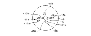
[ノズルプレートの構成]
図4はノズルプレート8を軸方向から見た図である。図4ではスワール室41と燃料分配室42の位置を点線で示している。ノズルプレート8には、軸方向に貫通する燃料噴射孔44が形成されている。この燃料噴射孔44は、2つの大径の燃料噴射孔44aと、2つの小径の燃料噴射孔44bとから構成されている。弁座部材7にノズルプレート8を溶接した際に、燃料噴射孔44aの中心とスワール付与室411aの中心が、燃料噴射孔44bの中心とスワール付与室411bの中心とが略一致するように形成されている。
燃料噴射孔44は隣り合う別の燃料噴射孔44からできるだけ離れた位置となるように形成され、各燃料噴射孔44から噴射された燃料噴霧が衝突しないように形成されている。
また、2つの大径の燃料噴射孔44aの導入通路410bは、他の2つの小径の燃料噴射孔41bの導入通路410bよりも長く設定されていることから、大径の燃料噴射孔44aは、小径の燃料噴射孔44bよりもノズルプレート8の中心より離れた位置に形成されている。
[Configuration of nozzle plate]
FIG. 4 is a view of the
The fuel injection holes 44 are formed so as to be located as far as possible from other adjacent fuel injection holes 44 so that the fuel sprays injected from the respective fuel injection holes 44 do not collide.
Further, since the
[作用]
次に実施例1の燃料噴射弁1の作用について説明する。
(燃料の微粒化)
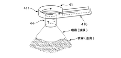
図5は弁座部材7およびノズルプレート8のスケルトン図である。なお、図5は略図でありスワール室41および燃料噴射孔44は1つのみ記載している。図6は、燃料が燃料分配室42からスワール室41を経て燃料噴射孔44に流れる流れの様子を示す図である。図7は、燃料がスワール室41を経て燃料噴射孔44から噴射される様子を断面で示す図である。なお、図7において燃料はハッチングで示され、空気層は白抜きで示されている。図8はスワール室41および燃料噴射孔44部分の拡大図であり、燃料噴射孔44から燃料が噴射される様子を示している。図9は、燃料噴射孔44から拡散される方向を示す図である。
開弁すると弁体4と弁座6との間から燃料が燃料分配室42に供給される。燃料分配室42に供給された燃料は、導入通路410を通りスワール付与室411に流れ込む。スワール付与室411に流れ込んだ燃料は、スワール付与室411内を旋回して旋回エネルギーを持ったまま燃料噴射孔44に供給される噴射される(図5、図6)。旋回エネルギーを持つ燃料は、燃料噴射孔44の壁部分に沿うように旋回しながら噴射される(図7、図8)。そのため、燃料噴射孔44から噴射された燃料は、燃料噴射孔44の接線方向に飛散する(図9)。燃料噴射孔44から噴射された直後の燃料噴霧は、燃料噴射孔44開口部のエッジ部分によって薄い液膜状態で円錐状に広がる。その後、液膜状態の燃料が分離して微粒化した液滴となる。
これにより燃料の気化を促進することができ、特に低温始動時の窒素酸化物等の発生を低減することができる。
[Action]
Next, the operation of the fuel injection valve 1 of the first embodiment will be described.
(Fuel atomization)
FIG. 5 is a skeleton diagram of the
When the valve is opened, fuel is supplied to the
As a result, fuel vaporization can be promoted, and in particular, generation of nitrogen oxides and the like during low temperature starting can be reduced.
(燃料噴霧の衝突防止)
噴射した燃料の微粒化を図るためには、燃料噴射孔44の径を小さくする必要がある。しかしながら、燃料噴射孔44の径を小さくすると1つの燃料噴射孔44から噴射することができる燃料噴射量は少量となるため、燃料噴射孔44を多数形成する必要がある。ノズルプレート8は、弁座部材7に溶接により固定されているため燃料噴射孔44を形成することができる範囲は限られており、燃料噴射孔44同士の距離が近いと隣り合う燃料噴霧が衝突し、液粒同士が結合して粗大粒が形成され、燃料の微粒化が抑制されるおそれがある。
一方、燃料噴射孔44の径を大きくすると1つの燃料噴射孔44が噴射することができる燃料噴射量は多量となるため、形成する燃料噴射孔44を少数にすることができる。しかしながら、燃料噴射孔44の径を大きくすると噴射した燃料が粗大化してしまう。
そこで実施例1の燃料噴射弁1では、各スワール室41に連通してスワールが付与された燃料を燃焼室側に噴射する径の異なる複数の燃料噴射孔を、隣り合う燃料噴射孔から噴射される燃料噴霧が重ならないように配置した。
図10は燃料噴射孔44から噴射された燃料噴霧の形状を示す図である。図11は燃料噴霧の拡散範囲を示す図である。図10、図11に示すように、大径の燃料噴射孔44aから噴射された燃料噴霧と小径の燃料噴射孔44bから噴射された燃料噴霧とは拡散範囲が被らず、燃料噴霧の衝突を防止することができる。そのため液粒の粗大化を防ぎ、燃料の気化を促進することができる。さらに、大径の燃料噴射孔44aと小径の燃料噴射孔44bとを形成したことにより燃料噴射量を確保しつつ、十分に微粒化した燃料もある割合以上確保することができる。
(Preventing collision of fuel spray)
In order to atomize the injected fuel, the diameter of the
On the other hand, when the diameter of the
Therefore, in the fuel injection valve 1 according to the first embodiment, a plurality of fuel injection holes having different diameters for injecting the swirled fuel into the combustion chamber side in communication with the
FIG. 10 is a view showing the shape of the fuel spray injected from the
(効率的なスワール付与)
燃料にスワールを効率良く付与できる導入通路410とスワール付与室411の形状は、導入通路410の長さ、断面積、スワール付与室411の径の大きさの比によって決定される。
そこで実施例1の燃料噴射弁1では、各燃料噴射孔44の形状を、相似形状に形成した。よって、燃料に効率的にスワールを付与することができ、燃料の微粒化を図ることができる。
(Efficient swirl grant)
The shapes of the
Therefore, in the fuel injection valve 1 of the first embodiment, the shape of each
[効果]
実施例1の燃料噴射弁1の効果について以下に列記する。
(1)燃料を供給するポンプ47と、摺動可能に設けられた弁体4と、閉弁時に弁体4が座る弁座6が一端側に形成された弁座部材7と、弁座部材7の他端側に形成され、燃料にスワールを付与する複数のスワール室41と、各スワール室41に連通してスワールが付与された燃料を燃焼室側に噴射する径の異なる複数の燃料噴射孔44を、隣り合う燃料噴射孔44から噴射される燃料噴霧が重ならないように配置したノズルプレート8とを設けた。
大径の燃料噴射孔44aから噴射された燃料噴霧と小径の燃料噴射孔44bから噴射された燃料噴霧とは拡散範囲が被らず、もしくは拡散が被る範囲を可及的に低減し、燃料噴霧の衝突を抑制することができる。そのため液粒の粗大化を防ぎ、燃料の気化を促進することができる。さらに、大径の燃料噴射孔44aと小径の燃料噴射孔44bとを形成したことにより燃料噴射量を確保しつつ、十分に微粒化した燃料もある割合以上確保することができる。
(2)複数のスワール室41および複数の燃料噴射孔44の形状を、相似形状に形成した
よって、燃料噴射孔44が大きいときには、導入通路410も長くなる。これによりスワール付与室411へ向かう燃料の流れを整流することができ、燃料に効率的にスワールを付与し、燃料の微粒化を図ることができる。
[effect]
The effects of the fuel injection valve 1 of the first embodiment are listed below.
(1) A
The fuel spray injected from the large-diameter
(2) Since the shapes of the plurality of
〔他の実施例〕
以上、本願発明を実施例1に基づいて説明してきたが、各発明の具体的な構成は各実施例に限定されるものではなく、発明の要旨を逸脱しない範囲の設計変更等があっても、本発明に含まれる。
実施例1の燃料噴射弁1では、2つの大きなスワール室41aと2つの小さなスワール室41b、2つの大径の燃料噴射孔44aと2つの小径の燃料噴射孔44bが形成されているが、それぞれの数は適宜設定しても良い。
図12は弁座部材7を軸方向他端側から見た図である。図13はノズルプレート8を軸方向から見た図である。図14は燃料噴霧の拡散範囲を示す図である。例えば、図12、図13に示すように、1つの大きなスワール室41aと2つの小さなスワール室41b、1つの大径の燃料噴射孔44aと2つの小径の燃料噴射孔44bを形成するようにしても良い。この場合であっても、図14に示すように大径の燃料噴射孔44aから噴射された燃料噴霧と小径の燃料噴射孔44bから噴射された燃料噴霧とは拡散範囲が被らないようにすれば良い。
[Other Examples]
As described above, the present invention has been described based on the first embodiment. However, the specific configuration of each invention is not limited to each embodiment, and even if there is a design change or the like without departing from the gist of the invention. Are included in the present invention.
In the fuel injection valve 1 of the first embodiment, two
FIG. 12 is a view of the
また実施例1の燃料噴射弁1では弁座部材7にスワール室41、燃料分配室42を形成するようにしていたが、中間プレート50を設けてこの中間プレート50にスワール室41、燃料分配室42を形成するようにしても良い。
図15は燃料噴射弁1のスワール室41付近の拡大断面図である。図15に示すように、中間プレート50にスワール室41、燃料分配室42を形成し、ノズルプレート8とともに中間プレート50を弁座部材7に溶接する。
またノズルプレート8にスワール室41、燃料分配室42を形成するようにしても良い。
図16は燃料噴射弁1のスワール室41付近の拡大断面図である。図16に示すように、ノズルプレート8にスワール室41、燃料分配室42、燃料噴射孔44が形成されている。
In the fuel injection valve 1 of the first embodiment, the
FIG. 15 is an enlarged sectional view of the vicinity of the
Further, the
FIG. 16 is an enlarged cross-sectional view of the vicinity of the
また実施例1の燃料噴射弁1ではスワール付与室411を円形に形成したが、他の形でも良い。
図17は、弁座部材7を軸方向他端側から見た図である。図17に示すように、スワール付与室411の壁は螺旋状に形成された凹状に形成されている。
In the fuel injection valve 1 of the first embodiment, the
FIG. 17 is a view of the
1 燃料噴射弁
4 弁体
6 弁座
7 弁座部材
8 ノズルプレート
41 スワール室
44 燃料噴射孔
1 Fuel injection valve
4 Disc
6 Valve seat
7 Valve seat member
8 Nozzle plate
41 Swirl room
44 Fuel injection hole
Claims (2)
摺動可能に設けられた弁体と、
閉弁時に前記弁体が座る弁座が一端側に形成された弁座部材と、
前記弁座部材の他端側に形成され、燃料にスワールを付与する複数のスワール室と、
各スワール室に連通して前記スワールが付与された燃料を燃焼室側に噴射する径の異なる複数の燃料噴射孔を、隣り合う前記燃料噴射孔から噴射される燃料噴霧が少なくとも液膜状態において重ならないように配置したノズルプレートと、
を設けた燃料噴射弁。 A pump for supplying fuel;
A valve body slidably provided;
A valve seat member formed on one end side of a valve seat on which the valve body sits when the valve is closed;
A plurality of swirl chambers formed on the other end side of the valve seat member for imparting a swirl to the fuel;
A plurality of fuel injection holes having different diameters, which communicate with each swirl chamber and inject the fuel to which the swirl has been applied, into the combustion chamber, are overlapped at least in a liquid film state. A nozzle plate arranged so as not to become
Fuel injection valve provided with
複数の前記スワール室および複数の前記燃料噴射孔の形状を、相似形状に形成したことを特徴とする燃料噴射弁。 The fuel injection valve according to claim 1, wherein
A fuel injection valve, wherein the plurality of swirl chambers and the plurality of fuel injection holes are formed in a similar shape.
Priority Applications (2)
| Application Number | Priority Date | Filing Date | Title |
|---|---|---|---|
| JP2010222513A JP5166500B2 (en) | 2010-09-30 | 2010-09-30 | Fuel injection valve |
| CN201110300862.2A CN102444511B (en) | 2010-09-30 | 2011-09-29 | Fuelinjection nozzle |
Applications Claiming Priority (1)
| Application Number | Priority Date | Filing Date | Title |
|---|---|---|---|
| JP2010222513A JP5166500B2 (en) | 2010-09-30 | 2010-09-30 | Fuel injection valve |
Publications (2)
| Publication Number | Publication Date |
|---|---|
| JP2012077664A JP2012077664A (en) | 2012-04-19 |
| JP5166500B2 true JP5166500B2 (en) | 2013-03-21 |
Family
ID=46007359
Family Applications (1)
| Application Number | Title | Priority Date | Filing Date |
|---|---|---|---|
| JP2010222513A Active JP5166500B2 (en) | 2010-09-30 | 2010-09-30 | Fuel injection valve |
Country Status (2)
| Country | Link |
|---|---|
| JP (1) | JP5166500B2 (en) |
| CN (1) | CN102444511B (en) |
Families Citing this family (7)
| Publication number | Priority date | Publication date | Assignee | Title |
|---|---|---|---|---|
| JP6239317B2 (en) * | 2013-08-29 | 2017-11-29 | 日立オートモティブシステムズ株式会社 | Fuel injection valve |
| JP6141350B2 (en) * | 2015-04-30 | 2017-06-07 | 三菱電機株式会社 | Fuel injection valve |
| WO2019087325A1 (en) * | 2017-11-01 | 2019-05-09 | 三菱電機株式会社 | Fuel injection valve |
| WO2019087326A1 (en) * | 2017-11-01 | 2019-05-09 | 三菱電機株式会社 | Fuel injection valve |
| JP7136630B2 (en) * | 2018-08-23 | 2022-09-13 | シチズンファインデバイス株式会社 | Manufacturing method of fluid spray plate |
| WO2021029295A1 (en) * | 2019-08-09 | 2021-02-18 | 日立オートモティブシステムズ株式会社 | Fuel injection valve |
| JP7281377B2 (en) * | 2019-09-18 | 2023-05-25 | 日立Astemo株式会社 | fuel injector |
Family Cites Families (7)
| Publication number | Priority date | Publication date | Assignee | Title |
|---|---|---|---|---|
| AT378244B (en) * | 1982-12-14 | 1985-07-10 | Steyr Daimler Puch Ag | INJECTION NOZZLE FOR AIR COMPRESSING, SELF-IGNITIONING PISTON PISTON COMBUSTION ENGINES |
| JPS60222557A (en) * | 1984-04-20 | 1985-11-07 | Hitachi Ltd | Electromagnetic fuel injection valve |
| DE3808396C2 (en) * | 1988-03-12 | 1995-05-04 | Bosch Gmbh Robert | Fuel injector |
| JP3377004B2 (en) * | 1996-10-25 | 2003-02-17 | 株式会社デンソー | Fluid injection nozzle |
| DE10041440A1 (en) * | 2000-08-23 | 2002-03-07 | Bosch Gmbh Robert | Swirl disk and fuel injector with swirl disk |
| DE10251698A1 (en) * | 2002-11-06 | 2004-06-03 | Robert Bosch Gmbh | metering |
| JP4300197B2 (en) * | 2005-06-03 | 2009-07-22 | 株式会社日立製作所 | Fuel injection valve and internal combustion engine using the same |
-
2010
- 2010-09-30 JP JP2010222513A patent/JP5166500B2/en active Active
-
2011
- 2011-09-29 CN CN201110300862.2A patent/CN102444511B/en active Active
Also Published As
| Publication number | Publication date |
|---|---|
| CN102444511B (en) | 2015-08-19 |
| JP2012077664A (en) | 2012-04-19 |
| CN102444511A (en) | 2012-05-09 |
Similar Documents
| Publication | Publication Date | Title |
|---|---|---|
| JP5166500B2 (en) | Fuel injection valve | |
| JP5200047B2 (en) | Fuel injection valve | |
| JP5253480B2 (en) | Fuel injection valve | |
| JP5852463B2 (en) | Fuel injection valve | |
| JP5336451B2 (en) | Fuel injection valve | |
| JP2012215135A (en) | Fuel injection valve | |
| JP5877768B2 (en) | Fuel injection valve | |
| JP2013194624A (en) | Fuel injection valve | |
| JP7049133B2 (en) | Fuel injection valve | |
| JP4024144B2 (en) | Fuel injection device | |
| JP2013185522A (en) | Fuel injection valve | |
| JP2012211532A (en) | Fuel injection valve | |
| JP2013194725A (en) | Fuel injection valve | |
| JP5341046B2 (en) | Fuel injection valve | |
| JP5341045B2 (en) | Fuel injection valve | |
| JP5492131B2 (en) | Fuel injection valve | |
| JP3933545B2 (en) | Fuel injection nozzle and fuel injection apparatus using the same | |
| JP5980706B2 (en) | Fuel injection valve | |
| JP2014181611A (en) | Fuel injection valve | |
| JP2008231928A (en) | Fuel injection valve | |
| JP5492133B2 (en) | Fuel injection valve | |
| JP2005325800A (en) | Fluid injection valve | |
| JP2014066186A (en) | Fuel injection valve | |
| JP5818856B2 (en) | Fuel injection valve | |
| JP2013194634A (en) | Fuel injection valve |
Legal Events
| Date | Code | Title | Description |
|---|---|---|---|
| A621 | Written request for application examination |
Free format text: JAPANESE INTERMEDIATE CODE: A621 Effective date: 20120215 |
|
| A977 | Report on retrieval |
Free format text: JAPANESE INTERMEDIATE CODE: A971007 Effective date: 20120719 |
|
| A131 | Notification of reasons for refusal |
Free format text: JAPANESE INTERMEDIATE CODE: A131 Effective date: 20120731 |
|
| A521 | Request for written amendment filed |
Free format text: JAPANESE INTERMEDIATE CODE: A523 Effective date: 20120928 |
|
| TRDD | Decision of grant or rejection written | ||
| A01 | Written decision to grant a patent or to grant a registration (utility model) |
Free format text: JAPANESE INTERMEDIATE CODE: A01 Effective date: 20121204 |
|
| A61 | First payment of annual fees (during grant procedure) |
Free format text: JAPANESE INTERMEDIATE CODE: A61 Effective date: 20121220 |
|
| FPAY | Renewal fee payment (event date is renewal date of database) |
Free format text: PAYMENT UNTIL: 20151228 Year of fee payment: 3 |
|
| R150 | Certificate of patent or registration of utility model |
Ref document number: 5166500 Country of ref document: JP Free format text: JAPANESE INTERMEDIATE CODE: R150 Free format text: JAPANESE INTERMEDIATE CODE: R150 |
|
| R250 | Receipt of annual fees |
Free format text: JAPANESE INTERMEDIATE CODE: R250 |
|
| R250 | Receipt of annual fees |
Free format text: JAPANESE INTERMEDIATE CODE: R250 |
|
| R250 | Receipt of annual fees |
Free format text: JAPANESE INTERMEDIATE CODE: R250 |
|
| R250 | Receipt of annual fees |
Free format text: JAPANESE INTERMEDIATE CODE: R250 |
|
| R250 | Receipt of annual fees |
Free format text: JAPANESE INTERMEDIATE CODE: R250 |
|
| R250 | Receipt of annual fees |
Free format text: JAPANESE INTERMEDIATE CODE: R250 |
|
| S533 | Written request for registration of change of name |
Free format text: JAPANESE INTERMEDIATE CODE: R313533 |
|
| R350 | Written notification of registration of transfer |
Free format text: JAPANESE INTERMEDIATE CODE: R350 |
|
| R250 | Receipt of annual fees |
Free format text: JAPANESE INTERMEDIATE CODE: R250 |
|
| R250 | Receipt of annual fees |
Free format text: JAPANESE INTERMEDIATE CODE: R250 |
|
| R250 | Receipt of annual fees |
Free format text: JAPANESE INTERMEDIATE CODE: R250 |