JP5166416B2 - PSA process using a composite adsorbent bed containing adsorbent and PCM aggregates - Google Patents
PSA process using a composite adsorbent bed containing adsorbent and PCM aggregates Download PDFInfo
- Publication number
- JP5166416B2 JP5166416B2 JP2009528763A JP2009528763A JP5166416B2 JP 5166416 B2 JP5166416 B2 JP 5166416B2 JP 2009528763 A JP2009528763 A JP 2009528763A JP 2009528763 A JP2009528763 A JP 2009528763A JP 5166416 B2 JP5166416 B2 JP 5166416B2
- Authority
- JP
- Japan
- Prior art keywords
- pcm
- density
- adsorbent
- psa
- particles
- Prior art date
- Legal status (The legal status is an assumption and is not a legal conclusion. Google has not performed a legal analysis and makes no representation as to the accuracy of the status listed.)
- Expired - Fee Related
Links
- 238000000034 method Methods 0.000 title claims abstract description 149
- 230000008569 process Effects 0.000 title claims abstract description 76
- 239000003463 adsorbent Substances 0.000 title claims description 128
- 239000002131 composite material Substances 0.000 title claims description 16
- 239000012782 phase change material Substances 0.000 claims abstract description 132
- 238000001179 sorption measurement Methods 0.000 claims abstract description 65
- 239000002245 particle Substances 0.000 claims description 103
- 239000007789 gas Substances 0.000 claims description 68
- 239000000203 mixture Substances 0.000 claims description 37
- 229910052751 metal Inorganic materials 0.000 claims description 36
- 239000002184 metal Substances 0.000 claims description 36
- 239000003094 microcapsule Substances 0.000 claims description 28
- 229910052760 oxygen Inorganic materials 0.000 claims description 19
- QVGXLLKOCUKJST-UHFFFAOYSA-N atomic oxygen Chemical compound [O] QVGXLLKOCUKJST-UHFFFAOYSA-N 0.000 claims description 18
- 239000001301 oxygen Substances 0.000 claims description 18
- OKTJSMMVPCPJKN-UHFFFAOYSA-N Carbon Chemical compound [C] OKTJSMMVPCPJKN-UHFFFAOYSA-N 0.000 claims description 16
- 229910002091 carbon monoxide Inorganic materials 0.000 claims description 14
- 239000004020 conductor Substances 0.000 claims description 13
- 229910052757 nitrogen Inorganic materials 0.000 claims description 13
- 238000003795 desorption Methods 0.000 claims description 12
- 238000001465 metallisation Methods 0.000 claims description 11
- 229910052799 carbon Inorganic materials 0.000 claims description 8
- 150000001875 compounds Chemical class 0.000 claims description 8
- 239000011230 binding agent Substances 0.000 claims description 7
- 230000015572 biosynthetic process Effects 0.000 claims description 7
- 229910052802 copper Inorganic materials 0.000 claims description 7
- 229910052763 palladium Inorganic materials 0.000 claims description 7
- 229910052709 silver Inorganic materials 0.000 claims description 6
- 229910045601 alloy Inorganic materials 0.000 claims description 5
- 239000000956 alloy Substances 0.000 claims description 5
- 150000002739 metals Chemical class 0.000 claims description 5
- 238000002156 mixing Methods 0.000 claims description 5
- 229910052759 nickel Inorganic materials 0.000 claims description 5
- 239000012188 paraffin wax Substances 0.000 claims description 5
- 150000003839 salts Chemical class 0.000 claims description 5
- 238000002336 sorption--desorption measurement Methods 0.000 claims description 4
- 229910052782 aluminium Inorganic materials 0.000 claims description 3
- 235000014113 dietary fatty acids Nutrition 0.000 claims description 3
- 239000000194 fatty acid Substances 0.000 claims description 3
- 229930195729 fatty acid Natural products 0.000 claims description 3
- 150000004665 fatty acids Chemical class 0.000 claims description 3
- 239000000835 fiber Substances 0.000 claims description 3
- 229910052737 gold Inorganic materials 0.000 claims description 3
- 229910052742 iron Inorganic materials 0.000 claims description 3
- QJGQUHMNIGDVPM-UHFFFAOYSA-N nitrogen group Chemical group [N] QJGQUHMNIGDVPM-UHFFFAOYSA-N 0.000 claims description 3
- 125000001997 phenyl group Chemical group [H]C1=C([H])C([H])=C(*)C([H])=C1[H] 0.000 claims description 3
- 239000002594 sorbent Substances 0.000 claims 1
- 230000000694 effects Effects 0.000 abstract description 13
- 239000010410 layer Substances 0.000 description 34
- 238000000926 separation method Methods 0.000 description 25
- IJGRMHOSHXDMSA-UHFFFAOYSA-N Atomic nitrogen Chemical compound N#N IJGRMHOSHXDMSA-UHFFFAOYSA-N 0.000 description 24
- 239000012071 phase Substances 0.000 description 22
- 230000008929 regeneration Effects 0.000 description 21
- 238000011069 regeneration method Methods 0.000 description 21
- 230000008859 change Effects 0.000 description 19
- 239000011324 bead Substances 0.000 description 16
- 238000000576 coating method Methods 0.000 description 16
- 239000011248 coating agent Substances 0.000 description 15
- 238000012360 testing method Methods 0.000 description 15
- 239000010457 zeolite Substances 0.000 description 14
- 239000000843 powder Substances 0.000 description 13
- 238000006243 chemical reaction Methods 0.000 description 12
- 239000000758 substrate Substances 0.000 description 12
- 229910021536 Zeolite Inorganic materials 0.000 description 11
- HNPSIPDUKPIQMN-UHFFFAOYSA-N dioxosilane;oxo(oxoalumanyloxy)alumane Chemical compound O=[Si]=O.O=[Al]O[Al]=O HNPSIPDUKPIQMN-UHFFFAOYSA-N 0.000 description 11
- 239000008188 pellet Substances 0.000 description 11
- 238000000151 deposition Methods 0.000 description 10
- KDLHZDBZIXYQEI-UHFFFAOYSA-N palladium Substances [Pd] KDLHZDBZIXYQEI-UHFFFAOYSA-N 0.000 description 10
- 229910052739 hydrogen Inorganic materials 0.000 description 9
- 239000000463 material Substances 0.000 description 9
- UFHFLCQGNIYNRP-UHFFFAOYSA-N Hydrogen Chemical compound [H][H] UFHFLCQGNIYNRP-UHFFFAOYSA-N 0.000 description 8
- 239000001257 hydrogen Substances 0.000 description 8
- 238000004519 manufacturing process Methods 0.000 description 8
- VNWKTOKETHGBQD-UHFFFAOYSA-N methane Chemical compound C VNWKTOKETHGBQD-UHFFFAOYSA-N 0.000 description 8
- PNEYBMLMFCGWSK-UHFFFAOYSA-N aluminium oxide Inorganic materials [O-2].[O-2].[O-2].[Al+3].[Al+3] PNEYBMLMFCGWSK-UHFFFAOYSA-N 0.000 description 7
- 230000008021 deposition Effects 0.000 description 7
- 238000011049 filling Methods 0.000 description 7
- 230000033001 locomotion Effects 0.000 description 7
- 239000003973 paint Substances 0.000 description 7
- 238000005507 spraying Methods 0.000 description 7
- 102100027271 40S ribosomal protein SA Human genes 0.000 description 6
- 101000694288 Homo sapiens 40S ribosomal protein SA Proteins 0.000 description 6
- 239000010949 copper Substances 0.000 description 6
- PXHVJJICTQNCMI-UHFFFAOYSA-N nickel Substances [Ni] PXHVJJICTQNCMI-UHFFFAOYSA-N 0.000 description 6
- 238000012856 packing Methods 0.000 description 6
- 238000000746 purification Methods 0.000 description 6
- 238000011067 equilibration Methods 0.000 description 5
- 239000002808 molecular sieve Substances 0.000 description 5
- 230000035515 penetration Effects 0.000 description 5
- 229920000642 polymer Polymers 0.000 description 5
- URGAHOPLAPQHLN-UHFFFAOYSA-N sodium aluminosilicate Chemical compound [Na+].[Al+3].[O-][Si]([O-])=O.[O-][Si]([O-])=O URGAHOPLAPQHLN-UHFFFAOYSA-N 0.000 description 5
- 239000007787 solid Substances 0.000 description 5
- 239000000126 substance Substances 0.000 description 5
- XKRFYHLGVUSROY-UHFFFAOYSA-N Argon Chemical compound [Ar] XKRFYHLGVUSROY-UHFFFAOYSA-N 0.000 description 4
- RYGMFSIKBFXOCR-UHFFFAOYSA-N Copper Chemical compound [Cu] RYGMFSIKBFXOCR-UHFFFAOYSA-N 0.000 description 4
- VYPSYNLAJGMNEJ-UHFFFAOYSA-N Silicium dioxide Chemical compound O=[Si]=O VYPSYNLAJGMNEJ-UHFFFAOYSA-N 0.000 description 4
- BQCADISMDOOEFD-UHFFFAOYSA-N Silver Chemical compound [Ag] BQCADISMDOOEFD-UHFFFAOYSA-N 0.000 description 4
- 230000008901 benefit Effects 0.000 description 4
- 239000011521 glass Substances 0.000 description 4
- 229930195733 hydrocarbon Natural products 0.000 description 4
- 150000002430 hydrocarbons Chemical class 0.000 description 4
- 230000006872 improvement Effects 0.000 description 4
- 230000002441 reversible effect Effects 0.000 description 4
- 239000000741 silica gel Substances 0.000 description 4
- 229910002027 silica gel Inorganic materials 0.000 description 4
- 238000002604 ultrasonography Methods 0.000 description 4
- 239000002253 acid Substances 0.000 description 3
- 230000004913 activation Effects 0.000 description 3
- 238000007906 compression Methods 0.000 description 3
- 230000006835 compression Effects 0.000 description 3
- 230000001351 cycling effect Effects 0.000 description 3
- 238000009826 distribution Methods 0.000 description 3
- 238000005516 engineering process Methods 0.000 description 3
- 239000012530 fluid Substances 0.000 description 3
- 239000000446 fuel Substances 0.000 description 3
- 239000007788 liquid Substances 0.000 description 3
- 238000005259 measurement Methods 0.000 description 3
- 239000002923 metal particle Substances 0.000 description 3
- 239000003345 natural gas Substances 0.000 description 3
- -1 paraffins Chemical class 0.000 description 3
- 239000004033 plastic Substances 0.000 description 3
- 229920003023 plastic Polymers 0.000 description 3
- 238000007873 sieving Methods 0.000 description 3
- 239000004332 silver Substances 0.000 description 3
- 238000004513 sizing Methods 0.000 description 3
- 241000894007 species Species 0.000 description 3
- 238000003786 synthesis reaction Methods 0.000 description 3
- 238000011282 treatment Methods 0.000 description 3
- 241000196324 Embryophyta Species 0.000 description 2
- 229920000877 Melamine resin Polymers 0.000 description 2
- ATUOYWHBWRKTHZ-UHFFFAOYSA-N Propane Chemical compound CCC ATUOYWHBWRKTHZ-UHFFFAOYSA-N 0.000 description 2
- 150000007513 acids Chemical class 0.000 description 2
- 238000005054 agglomeration Methods 0.000 description 2
- 230000002776 aggregation Effects 0.000 description 2
- 150000001298 alcohols Chemical class 0.000 description 2
- 229910000287 alkaline earth metal oxide Inorganic materials 0.000 description 2
- 238000013459 approach Methods 0.000 description 2
- 229910052786 argon Inorganic materials 0.000 description 2
- 239000000919 ceramic Substances 0.000 description 2
- 238000012512 characterization method Methods 0.000 description 2
- 239000011247 coating layer Substances 0.000 description 2
- 238000001816 cooling Methods 0.000 description 2
- 238000006114 decarboxylation reaction Methods 0.000 description 2
- 238000007599 discharging Methods 0.000 description 2
- 239000000428 dust Substances 0.000 description 2
- 239000003480 eluent Substances 0.000 description 2
- 238000002474 experimental method Methods 0.000 description 2
- IVJISJACKSSFGE-UHFFFAOYSA-N formaldehyde;1,3,5-triazine-2,4,6-triamine Chemical compound O=C.NC1=NC(N)=NC(N)=N1 IVJISJACKSSFGE-UHFFFAOYSA-N 0.000 description 2
- 150000004679 hydroxides Chemical class 0.000 description 2
- 239000012535 impurity Substances 0.000 description 2
- XEEYBQQBJWHFJM-UHFFFAOYSA-N iron Substances [Fe] XEEYBQQBJWHFJM-UHFFFAOYSA-N 0.000 description 2
- 230000007774 longterm Effects 0.000 description 2
- 238000005240 physical vapour deposition Methods 0.000 description 2
- 238000009832 plasma treatment Methods 0.000 description 2
- 238000012545 processing Methods 0.000 description 2
- 238000010926 purge Methods 0.000 description 2
- 238000004064 recycling Methods 0.000 description 2
- 239000010944 silver (metal) Substances 0.000 description 2
- 239000002904 solvent Substances 0.000 description 2
- 238000001991 steam methane reforming Methods 0.000 description 2
- 238000003756 stirring Methods 0.000 description 2
- 238000005382 thermal cycling Methods 0.000 description 2
- 238000001771 vacuum deposition Methods 0.000 description 2
- 230000000007 visual effect Effects 0.000 description 2
- XLYOFNOQVPJJNP-UHFFFAOYSA-N water Substances O XLYOFNOQVPJJNP-UHFFFAOYSA-N 0.000 description 2
- 235000012284 Bertholletia excelsa Nutrition 0.000 description 1
- 244000205479 Bertholletia excelsa Species 0.000 description 1
- ZAMOUSCENKQFHK-UHFFFAOYSA-N Chlorine atom Chemical compound [Cl] ZAMOUSCENKQFHK-UHFFFAOYSA-N 0.000 description 1
- OTMSDBZUPAUEDD-UHFFFAOYSA-N Ethane Chemical compound CC OTMSDBZUPAUEDD-UHFFFAOYSA-N 0.000 description 1
- VGGSQFUCUMXWEO-UHFFFAOYSA-N Ethene Chemical compound C=C VGGSQFUCUMXWEO-UHFFFAOYSA-N 0.000 description 1
- 239000005977 Ethylene Substances 0.000 description 1
- 101150003085 Pdcl gene Proteins 0.000 description 1
- 101100438229 Solanum tuberosum PCM4 gene Proteins 0.000 description 1
- NINIDFKCEFEMDL-UHFFFAOYSA-N Sulfur Chemical compound [S] NINIDFKCEFEMDL-UHFFFAOYSA-N 0.000 description 1
- 238000005299 abrasion Methods 0.000 description 1
- 239000006096 absorbing agent Substances 0.000 description 1
- NIXOWILDQLNWCW-UHFFFAOYSA-N acrylic acid group Chemical group C(C=C)(=O)O NIXOWILDQLNWCW-UHFFFAOYSA-N 0.000 description 1
- 230000009471 action Effects 0.000 description 1
- 239000000853 adhesive Substances 0.000 description 1
- 230000001070 adhesive effect Effects 0.000 description 1
- 230000000274 adsorptive effect Effects 0.000 description 1
- 238000013019 agitation Methods 0.000 description 1
- 150000001335 aliphatic alkanes Chemical class 0.000 description 1
- 239000003513 alkali Substances 0.000 description 1
- 150000001336 alkenes Chemical class 0.000 description 1
- 150000001412 amines Chemical class 0.000 description 1
- 125000004429 atom Chemical group 0.000 description 1
- 230000009286 beneficial effect Effects 0.000 description 1
- 239000002775 capsule Substances 0.000 description 1
- 125000004432 carbon atom Chemical group C* 0.000 description 1
- 230000015556 catabolic process Effects 0.000 description 1
- 230000003197 catalytic effect Effects 0.000 description 1
- 238000006555 catalytic reaction Methods 0.000 description 1
- 210000004534 cecum Anatomy 0.000 description 1
- 239000004568 cement Substances 0.000 description 1
- 239000003795 chemical substances by application Substances 0.000 description 1
- 239000000460 chlorine Substances 0.000 description 1
- 229910052801 chlorine Inorganic materials 0.000 description 1
- 239000004927 clay Substances 0.000 description 1
- 238000002485 combustion reaction Methods 0.000 description 1
- 238000005056 compaction Methods 0.000 description 1
- 239000008139 complexing agent Substances 0.000 description 1
- 238000012669 compression test Methods 0.000 description 1
- 230000001143 conditioned effect Effects 0.000 description 1
- 238000011109 contamination Methods 0.000 description 1
- 230000008878 coupling Effects 0.000 description 1
- 238000010168 coupling process Methods 0.000 description 1
- 238000005859 coupling reaction Methods 0.000 description 1
- 238000005520 cutting process Methods 0.000 description 1
- 125000004122 cyclic group Chemical group 0.000 description 1
- 230000007423 decrease Effects 0.000 description 1
- 238000007872 degassing Methods 0.000 description 1
- 238000006731 degradation reaction Methods 0.000 description 1
- 238000011161 development Methods 0.000 description 1
- 230000018109 developmental process Effects 0.000 description 1
- GDVKFRBCXAPAQJ-UHFFFAOYSA-A dialuminum;hexamagnesium;carbonate;hexadecahydroxide Chemical compound [OH-].[OH-].[OH-].[OH-].[OH-].[OH-].[OH-].[OH-].[OH-].[OH-].[OH-].[OH-].[OH-].[OH-].[OH-].[OH-].[Mg+2].[Mg+2].[Mg+2].[Mg+2].[Mg+2].[Mg+2].[Al+3].[Al+3].[O-]C([O-])=O GDVKFRBCXAPAQJ-UHFFFAOYSA-A 0.000 description 1
- 239000006185 dispersion Substances 0.000 description 1
- 238000001035 drying Methods 0.000 description 1
- 238000010891 electric arc Methods 0.000 description 1
- 238000010828 elution Methods 0.000 description 1
- 230000007613 environmental effect Effects 0.000 description 1
- 239000000374 eutectic mixture Substances 0.000 description 1
- 238000011156 evaluation Methods 0.000 description 1
- 238000001704 evaporation Methods 0.000 description 1
- 230000008020 evaporation Effects 0.000 description 1
- 238000001914 filtration Methods 0.000 description 1
- 239000010419 fine particle Substances 0.000 description 1
- 238000009472 formulation Methods 0.000 description 1
- 238000005194 fractionation Methods 0.000 description 1
- 125000000524 functional group Chemical group 0.000 description 1
- 238000010438 heat treatment Methods 0.000 description 1
- 239000001307 helium Substances 0.000 description 1
- 229910052734 helium Inorganic materials 0.000 description 1
- SWQJXJOGLNCZEY-UHFFFAOYSA-N helium atom Chemical compound [He] SWQJXJOGLNCZEY-UHFFFAOYSA-N 0.000 description 1
- 239000008240 homogeneous mixture Substances 0.000 description 1
- 229960001545 hydrotalcite Drugs 0.000 description 1
- 229910001701 hydrotalcite Inorganic materials 0.000 description 1
- 238000007654 immersion Methods 0.000 description 1
- 238000011065 in-situ storage Methods 0.000 description 1
- 150000002484 inorganic compounds Chemical class 0.000 description 1
- 229910010272 inorganic material Inorganic materials 0.000 description 1
- 238000009413 insulation Methods 0.000 description 1
- 239000007791 liquid phase Substances 0.000 description 1
- 239000011159 matrix material Substances 0.000 description 1
- 230000008018 melting Effects 0.000 description 1
- 238000002844 melting Methods 0.000 description 1
- 239000012528 membrane Substances 0.000 description 1
- 229910001092 metal group alloy Inorganic materials 0.000 description 1
- 229910000000 metal hydroxide Inorganic materials 0.000 description 1
- 229910044991 metal oxide Inorganic materials 0.000 description 1
- 150000004706 metal oxides Chemical class 0.000 description 1
- 238000005272 metallurgy Methods 0.000 description 1
- 239000004005 microsphere Substances 0.000 description 1
- 238000000465 moulding Methods 0.000 description 1
- 230000005405 multipole Effects 0.000 description 1
- 239000012299 nitrogen atmosphere Substances 0.000 description 1
- 230000006911 nucleation Effects 0.000 description 1
- 238000010899 nucleation Methods 0.000 description 1
- 150000002894 organic compounds Chemical class 0.000 description 1
- 125000002524 organometallic group Chemical group 0.000 description 1
- 230000010355 oscillation Effects 0.000 description 1
- 230000003647 oxidation Effects 0.000 description 1
- 238000007254 oxidation reaction Methods 0.000 description 1
- 235000011837 pasties Nutrition 0.000 description 1
- 238000005453 pelletization Methods 0.000 description 1
- 238000005325 percolation Methods 0.000 description 1
- 230000002093 peripheral effect Effects 0.000 description 1
- 238000002135 phase contrast microscopy Methods 0.000 description 1
- 238000004375 physisorption Methods 0.000 description 1
- 238000009372 pisciculture Methods 0.000 description 1
- 238000007747 plating Methods 0.000 description 1
- 229920001296 polysiloxane Polymers 0.000 description 1
- 239000011148 porous material Substances 0.000 description 1
- 238000002360 preparation method Methods 0.000 description 1
- 238000004801 process automation Methods 0.000 description 1
- 239000001294 propane Substances 0.000 description 1
- QQONPFPTGQHPMA-UHFFFAOYSA-N propylene Natural products CC=C QQONPFPTGQHPMA-UHFFFAOYSA-N 0.000 description 1
- 125000004805 propylene group Chemical group [H]C([H])([H])C([H])([*:1])C([H])([H])[*:2] 0.000 description 1
- 230000009467 reduction Effects 0.000 description 1
- 229920005989 resin Polymers 0.000 description 1
- 239000011347 resin Substances 0.000 description 1
- 230000000630 rising effect Effects 0.000 description 1
- 230000035939 shock Effects 0.000 description 1
- 239000007921 spray Substances 0.000 description 1
- 238000004544 sputter deposition Methods 0.000 description 1
- 239000010935 stainless steel Substances 0.000 description 1
- 229910001220 stainless steel Inorganic materials 0.000 description 1
- 238000000629 steam reforming Methods 0.000 description 1
- 238000005728 strengthening Methods 0.000 description 1
- 229910052717 sulfur Inorganic materials 0.000 description 1
- 239000011593 sulfur Substances 0.000 description 1
- 238000004381 surface treatment Methods 0.000 description 1
- 239000010409 thin film Substances 0.000 description 1
- 230000001988 toxicity Effects 0.000 description 1
- 231100000419 toxicity Toxicity 0.000 description 1
- 230000001052 transient effect Effects 0.000 description 1
- 230000007704 transition Effects 0.000 description 1
- 238000009827 uniform distribution Methods 0.000 description 1
- 238000007740 vapor deposition Methods 0.000 description 1
- 239000003981 vehicle Substances 0.000 description 1
Images


Classifications
-
- B—PERFORMING OPERATIONS; TRANSPORTING
- B01—PHYSICAL OR CHEMICAL PROCESSES OR APPARATUS IN GENERAL
- B01D—SEPARATION
- B01D53/00—Separation of gases or vapours; Recovering vapours of volatile solvents from gases; Chemical or biological purification of waste gases, e.g. engine exhaust gases, smoke, fumes, flue gases, aerosols
- B01D53/02—Separation of gases or vapours; Recovering vapours of volatile solvents from gases; Chemical or biological purification of waste gases, e.g. engine exhaust gases, smoke, fumes, flue gases, aerosols by adsorption, e.g. preparative gas chromatography
-
- B—PERFORMING OPERATIONS; TRANSPORTING
- B01—PHYSICAL OR CHEMICAL PROCESSES OR APPARATUS IN GENERAL
- B01J—CHEMICAL OR PHYSICAL PROCESSES, e.g. CATALYSIS OR COLLOID CHEMISTRY; THEIR RELEVANT APPARATUS
- B01J20/00—Solid sorbent compositions or filter aid compositions; Sorbents for chromatography; Processes for preparing, regenerating or reactivating thereof
- B01J20/28—Solid sorbent compositions or filter aid compositions; Sorbents for chromatography; Processes for preparing, regenerating or reactivating thereof characterised by their form or physical properties
-
- B—PERFORMING OPERATIONS; TRANSPORTING
- B01—PHYSICAL OR CHEMICAL PROCESSES OR APPARATUS IN GENERAL
- B01D—SEPARATION
- B01D53/00—Separation of gases or vapours; Recovering vapours of volatile solvents from gases; Chemical or biological purification of waste gases, e.g. engine exhaust gases, smoke, fumes, flue gases, aerosols
- B01D53/02—Separation of gases or vapours; Recovering vapours of volatile solvents from gases; Chemical or biological purification of waste gases, e.g. engine exhaust gases, smoke, fumes, flue gases, aerosols by adsorption, e.g. preparative gas chromatography
- B01D53/04—Separation of gases or vapours; Recovering vapours of volatile solvents from gases; Chemical or biological purification of waste gases, e.g. engine exhaust gases, smoke, fumes, flue gases, aerosols by adsorption, e.g. preparative gas chromatography with stationary adsorbents
-
- B—PERFORMING OPERATIONS; TRANSPORTING
- B01—PHYSICAL OR CHEMICAL PROCESSES OR APPARATUS IN GENERAL
- B01J—CHEMICAL OR PHYSICAL PROCESSES, e.g. CATALYSIS OR COLLOID CHEMISTRY; THEIR RELEVANT APPARATUS
- B01J20/00—Solid sorbent compositions or filter aid compositions; Sorbents for chromatography; Processes for preparing, regenerating or reactivating thereof
- B01J20/02—Solid sorbent compositions or filter aid compositions; Sorbents for chromatography; Processes for preparing, regenerating or reactivating thereof comprising inorganic material
- B01J20/06—Solid sorbent compositions or filter aid compositions; Sorbents for chromatography; Processes for preparing, regenerating or reactivating thereof comprising inorganic material comprising oxides or hydroxides of metals not provided for in group B01J20/04
- B01J20/08—Solid sorbent compositions or filter aid compositions; Sorbents for chromatography; Processes for preparing, regenerating or reactivating thereof comprising inorganic material comprising oxides or hydroxides of metals not provided for in group B01J20/04 comprising aluminium oxide or hydroxide; comprising bauxite
-
- B—PERFORMING OPERATIONS; TRANSPORTING
- B01—PHYSICAL OR CHEMICAL PROCESSES OR APPARATUS IN GENERAL
- B01J—CHEMICAL OR PHYSICAL PROCESSES, e.g. CATALYSIS OR COLLOID CHEMISTRY; THEIR RELEVANT APPARATUS
- B01J20/00—Solid sorbent compositions or filter aid compositions; Sorbents for chromatography; Processes for preparing, regenerating or reactivating thereof
- B01J20/02—Solid sorbent compositions or filter aid compositions; Sorbents for chromatography; Processes for preparing, regenerating or reactivating thereof comprising inorganic material
- B01J20/10—Solid sorbent compositions or filter aid compositions; Sorbents for chromatography; Processes for preparing, regenerating or reactivating thereof comprising inorganic material comprising silica or silicate
- B01J20/103—Solid sorbent compositions or filter aid compositions; Sorbents for chromatography; Processes for preparing, regenerating or reactivating thereof comprising inorganic material comprising silica or silicate comprising silica
-
- B—PERFORMING OPERATIONS; TRANSPORTING
- B01—PHYSICAL OR CHEMICAL PROCESSES OR APPARATUS IN GENERAL
- B01J—CHEMICAL OR PHYSICAL PROCESSES, e.g. CATALYSIS OR COLLOID CHEMISTRY; THEIR RELEVANT APPARATUS
- B01J20/00—Solid sorbent compositions or filter aid compositions; Sorbents for chromatography; Processes for preparing, regenerating or reactivating thereof
- B01J20/02—Solid sorbent compositions or filter aid compositions; Sorbents for chromatography; Processes for preparing, regenerating or reactivating thereof comprising inorganic material
- B01J20/10—Solid sorbent compositions or filter aid compositions; Sorbents for chromatography; Processes for preparing, regenerating or reactivating thereof comprising inorganic material comprising silica or silicate
- B01J20/16—Alumino-silicates
- B01J20/18—Synthetic zeolitic molecular sieves
-
- B—PERFORMING OPERATIONS; TRANSPORTING
- B01—PHYSICAL OR CHEMICAL PROCESSES OR APPARATUS IN GENERAL
- B01J—CHEMICAL OR PHYSICAL PROCESSES, e.g. CATALYSIS OR COLLOID CHEMISTRY; THEIR RELEVANT APPARATUS
- B01J20/00—Solid sorbent compositions or filter aid compositions; Sorbents for chromatography; Processes for preparing, regenerating or reactivating thereof
- B01J20/02—Solid sorbent compositions or filter aid compositions; Sorbents for chromatography; Processes for preparing, regenerating or reactivating thereof comprising inorganic material
- B01J20/20—Solid sorbent compositions or filter aid compositions; Sorbents for chromatography; Processes for preparing, regenerating or reactivating thereof comprising inorganic material comprising free carbon; comprising carbon obtained by carbonising processes
-
- B—PERFORMING OPERATIONS; TRANSPORTING
- B01—PHYSICAL OR CHEMICAL PROCESSES OR APPARATUS IN GENERAL
- B01J—CHEMICAL OR PHYSICAL PROCESSES, e.g. CATALYSIS OR COLLOID CHEMISTRY; THEIR RELEVANT APPARATUS
- B01J20/00—Solid sorbent compositions or filter aid compositions; Sorbents for chromatography; Processes for preparing, regenerating or reactivating thereof
- B01J20/28—Solid sorbent compositions or filter aid compositions; Sorbents for chromatography; Processes for preparing, regenerating or reactivating thereof characterised by their form or physical properties
- B01J20/28002—Solid sorbent compositions or filter aid compositions; Sorbents for chromatography; Processes for preparing, regenerating or reactivating thereof characterised by their form or physical properties characterised by their physical properties
- B01J20/28011—Other properties, e.g. density, crush strength
-
- B—PERFORMING OPERATIONS; TRANSPORTING
- B01—PHYSICAL OR CHEMICAL PROCESSES OR APPARATUS IN GENERAL
- B01J—CHEMICAL OR PHYSICAL PROCESSES, e.g. CATALYSIS OR COLLOID CHEMISTRY; THEIR RELEVANT APPARATUS
- B01J20/00—Solid sorbent compositions or filter aid compositions; Sorbents for chromatography; Processes for preparing, regenerating or reactivating thereof
- B01J20/30—Processes for preparing, regenerating, or reactivating
- B01J20/3042—Use of binding agents; addition of materials ameliorating the mechanical properties of the produced sorbent
-
- B—PERFORMING OPERATIONS; TRANSPORTING
- B01—PHYSICAL OR CHEMICAL PROCESSES OR APPARATUS IN GENERAL
- B01J—CHEMICAL OR PHYSICAL PROCESSES, e.g. CATALYSIS OR COLLOID CHEMISTRY; THEIR RELEVANT APPARATUS
- B01J20/00—Solid sorbent compositions or filter aid compositions; Sorbents for chromatography; Processes for preparing, regenerating or reactivating thereof
- B01J20/30—Processes for preparing, regenerating, or reactivating
- B01J20/34—Regenerating or reactivating
- B01J20/3408—Regenerating or reactivating of aluminosilicate molecular sieves
-
- B—PERFORMING OPERATIONS; TRANSPORTING
- B01—PHYSICAL OR CHEMICAL PROCESSES OR APPARATUS IN GENERAL
- B01J—CHEMICAL OR PHYSICAL PROCESSES, e.g. CATALYSIS OR COLLOID CHEMISTRY; THEIR RELEVANT APPARATUS
- B01J20/00—Solid sorbent compositions or filter aid compositions; Sorbents for chromatography; Processes for preparing, regenerating or reactivating thereof
- B01J20/30—Processes for preparing, regenerating, or reactivating
- B01J20/34—Regenerating or reactivating
- B01J20/3416—Regenerating or reactivating of sorbents or filter aids comprising free carbon, e.g. activated carbon
-
- B—PERFORMING OPERATIONS; TRANSPORTING
- B01—PHYSICAL OR CHEMICAL PROCESSES OR APPARATUS IN GENERAL
- B01J—CHEMICAL OR PHYSICAL PROCESSES, e.g. CATALYSIS OR COLLOID CHEMISTRY; THEIR RELEVANT APPARATUS
- B01J20/00—Solid sorbent compositions or filter aid compositions; Sorbents for chromatography; Processes for preparing, regenerating or reactivating thereof
- B01J20/30—Processes for preparing, regenerating, or reactivating
- B01J20/34—Regenerating or reactivating
- B01J20/3433—Regenerating or reactivating of sorbents or filter aids other than those covered by B01J20/3408 - B01J20/3425
-
- B—PERFORMING OPERATIONS; TRANSPORTING
- B01—PHYSICAL OR CHEMICAL PROCESSES OR APPARATUS IN GENERAL
- B01J—CHEMICAL OR PHYSICAL PROCESSES, e.g. CATALYSIS OR COLLOID CHEMISTRY; THEIR RELEVANT APPARATUS
- B01J20/00—Solid sorbent compositions or filter aid compositions; Sorbents for chromatography; Processes for preparing, regenerating or reactivating thereof
- B01J20/30—Processes for preparing, regenerating, or reactivating
- B01J20/34—Regenerating or reactivating
- B01J20/3491—Regenerating or reactivating by pressure treatment
-
- B—PERFORMING OPERATIONS; TRANSPORTING
- B01—PHYSICAL OR CHEMICAL PROCESSES OR APPARATUS IN GENERAL
- B01D—SEPARATION
- B01D2253/00—Adsorbents used in seperation treatment of gases and vapours
- B01D2253/10—Inorganic adsorbents
- B01D2253/102—Carbon
-
- B—PERFORMING OPERATIONS; TRANSPORTING
- B01—PHYSICAL OR CHEMICAL PROCESSES OR APPARATUS IN GENERAL
- B01D—SEPARATION
- B01D2253/00—Adsorbents used in seperation treatment of gases and vapours
- B01D2253/10—Inorganic adsorbents
- B01D2253/104—Alumina
-
- B—PERFORMING OPERATIONS; TRANSPORTING
- B01—PHYSICAL OR CHEMICAL PROCESSES OR APPARATUS IN GENERAL
- B01D—SEPARATION
- B01D2253/00—Adsorbents used in seperation treatment of gases and vapours
- B01D2253/10—Inorganic adsorbents
- B01D2253/106—Silica or silicates
-
- B—PERFORMING OPERATIONS; TRANSPORTING
- B01—PHYSICAL OR CHEMICAL PROCESSES OR APPARATUS IN GENERAL
- B01D—SEPARATION
- B01D2253/00—Adsorbents used in seperation treatment of gases and vapours
- B01D2253/10—Inorganic adsorbents
- B01D2253/106—Silica or silicates
- B01D2253/108—Zeolites
-
- B—PERFORMING OPERATIONS; TRANSPORTING
- B01—PHYSICAL OR CHEMICAL PROCESSES OR APPARATUS IN GENERAL
- B01D—SEPARATION
- B01D2253/00—Adsorbents used in seperation treatment of gases and vapours
- B01D2253/25—Coated, impregnated or composite adsorbents
-
- B—PERFORMING OPERATIONS; TRANSPORTING
- B01—PHYSICAL OR CHEMICAL PROCESSES OR APPARATUS IN GENERAL
- B01D—SEPARATION
- B01D2253/00—Adsorbents used in seperation treatment of gases and vapours
- B01D2253/30—Physical properties of adsorbents
- B01D2253/302—Dimensions
- B01D2253/304—Linear dimensions, e.g. particle shape, diameter
-
- B—PERFORMING OPERATIONS; TRANSPORTING
- B01—PHYSICAL OR CHEMICAL PROCESSES OR APPARATUS IN GENERAL
- B01D—SEPARATION
- B01D2256/00—Main component in the product gas stream after treatment
- B01D2256/10—Nitrogen
-
- B—PERFORMING OPERATIONS; TRANSPORTING
- B01—PHYSICAL OR CHEMICAL PROCESSES OR APPARATUS IN GENERAL
- B01D—SEPARATION
- B01D2256/00—Main component in the product gas stream after treatment
- B01D2256/12—Oxygen
-
- B—PERFORMING OPERATIONS; TRANSPORTING
- B01—PHYSICAL OR CHEMICAL PROCESSES OR APPARATUS IN GENERAL
- B01D—SEPARATION
- B01D2256/00—Main component in the product gas stream after treatment
- B01D2256/16—Hydrogen
-
- B—PERFORMING OPERATIONS; TRANSPORTING
- B01—PHYSICAL OR CHEMICAL PROCESSES OR APPARATUS IN GENERAL
- B01D—SEPARATION
- B01D2256/00—Main component in the product gas stream after treatment
- B01D2256/22—Carbon dioxide
-
- B—PERFORMING OPERATIONS; TRANSPORTING
- B01—PHYSICAL OR CHEMICAL PROCESSES OR APPARATUS IN GENERAL
- B01D—SEPARATION
- B01D2257/00—Components to be removed
- B01D2257/10—Single element gases other than halogens
- B01D2257/102—Nitrogen
-
- B—PERFORMING OPERATIONS; TRANSPORTING
- B01—PHYSICAL OR CHEMICAL PROCESSES OR APPARATUS IN GENERAL
- B01D—SEPARATION
- B01D2257/00—Components to be removed
- B01D2257/10—Single element gases other than halogens
- B01D2257/104—Oxygen
-
- B—PERFORMING OPERATIONS; TRANSPORTING
- B01—PHYSICAL OR CHEMICAL PROCESSES OR APPARATUS IN GENERAL
- B01D—SEPARATION
- B01D2257/00—Components to be removed
- B01D2257/10—Single element gases other than halogens
- B01D2257/108—Hydrogen
-
- B—PERFORMING OPERATIONS; TRANSPORTING
- B01—PHYSICAL OR CHEMICAL PROCESSES OR APPARATUS IN GENERAL
- B01D—SEPARATION
- B01D2257/00—Components to be removed
- B01D2257/50—Carbon oxides
- B01D2257/504—Carbon dioxide
-
- B—PERFORMING OPERATIONS; TRANSPORTING
- B01—PHYSICAL OR CHEMICAL PROCESSES OR APPARATUS IN GENERAL
- B01D—SEPARATION
- B01D2257/00—Components to be removed
- B01D2257/70—Organic compounds not provided for in groups B01D2257/00 - B01D2257/602
- B01D2257/702—Hydrocarbons
-
- B—PERFORMING OPERATIONS; TRANSPORTING
- B01—PHYSICAL OR CHEMICAL PROCESSES OR APPARATUS IN GENERAL
- B01D—SEPARATION
- B01D2258/00—Sources of waste gases
- B01D2258/02—Other waste gases
- B01D2258/0208—Other waste gases from fuel cells
-
- B—PERFORMING OPERATIONS; TRANSPORTING
- B01—PHYSICAL OR CHEMICAL PROCESSES OR APPARATUS IN GENERAL
- B01D—SEPARATION
- B01D2258/00—Sources of waste gases
- B01D2258/02—Other waste gases
- B01D2258/0233—Other waste gases from cement factories
-
- B—PERFORMING OPERATIONS; TRANSPORTING
- B01—PHYSICAL OR CHEMICAL PROCESSES OR APPARATUS IN GENERAL
- B01D—SEPARATION
- B01D2258/00—Sources of waste gases
- B01D2258/02—Other waste gases
- B01D2258/025—Other waste gases from metallurgy plants
-
- B—PERFORMING OPERATIONS; TRANSPORTING
- B01—PHYSICAL OR CHEMICAL PROCESSES OR APPARATUS IN GENERAL
- B01D—SEPARATION
- B01D2259/00—Type of treatment
- B01D2259/40—Further details for adsorption processes and devices
- B01D2259/414—Further details for adsorption processes and devices using different types of adsorbents
- B01D2259/4141—Further details for adsorption processes and devices using different types of adsorbents within a single bed
- B01D2259/4145—Further details for adsorption processes and devices using different types of adsorbents within a single bed arranged in series
- B01D2259/4146—Contiguous multilayered adsorbents
-
- B—PERFORMING OPERATIONS; TRANSPORTING
- B01—PHYSICAL OR CHEMICAL PROCESSES OR APPARATUS IN GENERAL
- B01D—SEPARATION
- B01D2259/00—Type of treatment
- B01D2259/40—Further details for adsorption processes and devices
- B01D2259/416—Further details for adsorption processes and devices involving cryogenic temperature treatment
-
- B—PERFORMING OPERATIONS; TRANSPORTING
- B01—PHYSICAL OR CHEMICAL PROCESSES OR APPARATUS IN GENERAL
- B01D—SEPARATION
- B01D2259/00—Type of treatment
- B01D2259/45—Gas separation or purification devices adapted for specific applications
- B01D2259/4533—Gas separation or purification devices adapted for specific applications for medical purposes
-
- B—PERFORMING OPERATIONS; TRANSPORTING
- B01—PHYSICAL OR CHEMICAL PROCESSES OR APPARATUS IN GENERAL
- B01D—SEPARATION
- B01D2259/00—Type of treatment
- B01D2259/45—Gas separation or purification devices adapted for specific applications
- B01D2259/4566—Gas separation or purification devices adapted for specific applications for use in transportation means
- B01D2259/4575—Gas separation or purification devices adapted for specific applications for use in transportation means in aeroplanes or space ships
-
- B—PERFORMING OPERATIONS; TRANSPORTING
- B01—PHYSICAL OR CHEMICAL PROCESSES OR APPARATUS IN GENERAL
- B01D—SEPARATION
- B01D2259/00—Type of treatment
- B01D2259/65—Employing advanced heat integration, e.g. Pinch technology
- B01D2259/655—Employing advanced heat integration, e.g. Pinch technology using heat storage materials
- B01D2259/657—Employing advanced heat integration, e.g. Pinch technology using heat storage materials using latent heat, e.g. with phase change materials
-
- B—PERFORMING OPERATIONS; TRANSPORTING
- B01—PHYSICAL OR CHEMICAL PROCESSES OR APPARATUS IN GENERAL
- B01D—SEPARATION
- B01D53/00—Separation of gases or vapours; Recovering vapours of volatile solvents from gases; Chemical or biological purification of waste gases, e.g. engine exhaust gases, smoke, fumes, flue gases, aerosols
- B01D53/02—Separation of gases or vapours; Recovering vapours of volatile solvents from gases; Chemical or biological purification of waste gases, e.g. engine exhaust gases, smoke, fumes, flue gases, aerosols by adsorption, e.g. preparative gas chromatography
- B01D53/04—Separation of gases or vapours; Recovering vapours of volatile solvents from gases; Chemical or biological purification of waste gases, e.g. engine exhaust gases, smoke, fumes, flue gases, aerosols by adsorption, e.g. preparative gas chromatography with stationary adsorbents
- B01D53/0407—Constructional details of adsorbing systems
- B01D53/0431—Beds with radial gas flow
-
- B—PERFORMING OPERATIONS; TRANSPORTING
- B01—PHYSICAL OR CHEMICAL PROCESSES OR APPARATUS IN GENERAL
- B01D—SEPARATION
- B01D53/00—Separation of gases or vapours; Recovering vapours of volatile solvents from gases; Chemical or biological purification of waste gases, e.g. engine exhaust gases, smoke, fumes, flue gases, aerosols
- B01D53/02—Separation of gases or vapours; Recovering vapours of volatile solvents from gases; Chemical or biological purification of waste gases, e.g. engine exhaust gases, smoke, fumes, flue gases, aerosols by adsorption, e.g. preparative gas chromatography
- B01D53/04—Separation of gases or vapours; Recovering vapours of volatile solvents from gases; Chemical or biological purification of waste gases, e.g. engine exhaust gases, smoke, fumes, flue gases, aerosols by adsorption, e.g. preparative gas chromatography with stationary adsorbents
- B01D53/047—Pressure swing adsorption
-
- B—PERFORMING OPERATIONS; TRANSPORTING
- B01—PHYSICAL OR CHEMICAL PROCESSES OR APPARATUS IN GENERAL
- B01J—CHEMICAL OR PHYSICAL PROCESSES, e.g. CATALYSIS OR COLLOID CHEMISTRY; THEIR RELEVANT APPARATUS
- B01J2220/00—Aspects relating to sorbent materials
- B01J2220/40—Aspects relating to the composition of sorbent or filter aid materials
- B01J2220/46—Materials comprising a mixture of inorganic and organic materials
-
- B—PERFORMING OPERATIONS; TRANSPORTING
- B01—PHYSICAL OR CHEMICAL PROCESSES OR APPARATUS IN GENERAL
- B01J—CHEMICAL OR PHYSICAL PROCESSES, e.g. CATALYSIS OR COLLOID CHEMISTRY; THEIR RELEVANT APPARATUS
- B01J2220/00—Aspects relating to sorbent materials
- B01J2220/50—Aspects relating to the use of sorbent or filter aid materials
- B01J2220/56—Use in the form of a bed
-
- B—PERFORMING OPERATIONS; TRANSPORTING
- B01—PHYSICAL OR CHEMICAL PROCESSES OR APPARATUS IN GENERAL
- B01J—CHEMICAL OR PHYSICAL PROCESSES, e.g. CATALYSIS OR COLLOID CHEMISTRY; THEIR RELEVANT APPARATUS
- B01J2220/00—Aspects relating to sorbent materials
- B01J2220/50—Aspects relating to the use of sorbent or filter aid materials
- B01J2220/60—Use in several different columns
- B01J2220/603—Use in several different columns serially disposed columns
-
- Y—GENERAL TAGGING OF NEW TECHNOLOGICAL DEVELOPMENTS; GENERAL TAGGING OF CROSS-SECTIONAL TECHNOLOGIES SPANNING OVER SEVERAL SECTIONS OF THE IPC; TECHNICAL SUBJECTS COVERED BY FORMER USPC CROSS-REFERENCE ART COLLECTIONS [XRACs] AND DIGESTS
- Y02—TECHNOLOGIES OR APPLICATIONS FOR MITIGATION OR ADAPTATION AGAINST CLIMATE CHANGE
- Y02C—CAPTURE, STORAGE, SEQUESTRATION OR DISPOSAL OF GREENHOUSE GASES [GHG]
- Y02C20/00—Capture or disposal of greenhouse gases
- Y02C20/40—Capture or disposal of greenhouse gases of CO2
Landscapes
- Chemical & Material Sciences (AREA)
- Analytical Chemistry (AREA)
- Chemical Kinetics & Catalysis (AREA)
- Organic Chemistry (AREA)
- Inorganic Chemistry (AREA)
- Engineering & Computer Science (AREA)
- General Chemical & Material Sciences (AREA)
- Oil, Petroleum & Natural Gas (AREA)
- Materials Engineering (AREA)
- Solid-Sorbent Or Filter-Aiding Compositions (AREA)
- Separation Of Gases By Adsorption (AREA)
Abstract
Description
本発明は、各サイクル中に熱サイクル法にさらされる熱的効果を低減させるための、相変化物質(PCM)を含有する凝集体を用いる、短いサイクル時間、典型的には30分未満のサイクル時間を有する熱サイクル法、特にPSA(圧力スイング吸着)法に関する。 The present invention uses short cycle times, typically less than 30 minutes cycles, using aggregates containing phase change material (PCM) to reduce the thermal effects exposed to the thermal cycling process during each cycle. The present invention relates to a heat cycle method having time, and more particularly to a PSA (pressure swing adsorption) method.
「熱サイクル法」という表現は、ある工程が発熱性である、すなわち熱の放出を伴う一方、ある他の工程は吸熱性の、すなわち熱の消費を伴う、いずれものサイクル法である。 The expression "thermal cycle method" is any cycle method in which one process is exothermic, i.e. involving the release of heat, while another process is endothermic, i.e. involving the consumption of heat.
本発明による熱サイクル法の典型的な例は、
圧力スイング吸着、例えばPSA(圧力スイング吸着)法、VSA(真空スイング吸着)法、VPSA(減圧スイング吸着)法、およびMPSA(混合圧力スイング吸着)法によるガス分離のための方法、
上記した圧力スイング吸着サイクルに加えて化学変換を用い、化学反応の平衡をシフトさせることができるいずれもの方法、
を含む。
A typical example of a thermal cycling method according to the present invention is:
Pressure swing adsorption, for example gas separation by PSA (pressure swing adsorption) method, VSA (vacuum swing adsorption) method, VPSA (vacuum swing adsorption) method, and MPSA (mixed pressure swing adsorption) method,
Any method that can shift the equilibrium of a chemical reaction using chemical transformation in addition to the pressure swing adsorption cycle described above,
including.
圧力スイング吸着を経る分離のための方法は、物理吸着の現象に依存し、1種以上の吸着床、例えばゼオライト、活性炭、活性アルミナ、シリカゲル、モレキュラーシーブ、または同様の床を通じて処理されるガスの圧力サイクリングによるガスの分離または精製を可能にする。 The method for separation via pressure swing adsorption depends on the phenomenon of physisorption and depends on the gas being processed through one or more adsorbent beds, such as zeolite, activated carbon, activated alumina, silica gel, molecular sieves, or similar beds. Allows gas separation or purification by pressure cycling.
本発明の関連で、「PSA法」という語は、他に述べない限り、吸着圧力として知られる高圧と、再生圧力として知られる低圧との間の圧力の周期変動を用いて、圧力スイング吸着を経るガス分離のためのいずれもの方法を意味するものと理解される。その結果として、一般名PSA法を、以下のサイクル法:
吸着を「高圧」と呼ばれる大気圧において、すなわち、1バール絶対圧〜1.6バール絶対圧、好ましくは1.1〜1.5バール絶対圧において実質的に行い、「低圧」と呼ばれる脱着圧力は大気圧よりも低く、典型的に30〜800ミリバール絶対圧、好ましくは100〜600ミリバール絶対圧であるVSA法;
吸着を、大気圧よりも実質的に高い圧力において、一般的に1.6〜8バール絶対圧、好ましくは2〜6バール絶対圧において行い、低圧は、大気圧以下、典型的に30〜800ミリバール絶対圧、好ましくは100〜600ミリバール絶対圧であるVPSAまたはMPSA法、および
吸着を、大気圧よりも著しく高い圧力、典型的には1.6〜50バール絶対圧、好ましくは2〜35バール絶対圧において行い、低圧が、大気圧よりも高いか、実質的に等しく、従って、1〜9バール絶対圧、好ましくは1.2〜2.5バール絶対圧であるPSA法
を示すために同じように用いる。
In the context of the present invention, the term “PSA method” refers to pressure swing adsorption using a cyclic variation in pressure between a high pressure known as the adsorption pressure and a low pressure known as the regeneration pressure, unless stated otherwise. It is understood to mean any method for gas separation via. As a result, the generic name PSA method was changed to the following cycle method:
Adsorption takes place substantially at atmospheric pressure called “high pressure”, ie 1 bar absolute pressure to 1.6 bar absolute pressure, preferably 1.1 to 1.5 bar absolute pressure, desorption pressure called “low pressure” Is a VSA process below atmospheric pressure, typically 30-800 mbar absolute pressure, preferably 100-600 mbar absolute pressure;
Adsorption is carried out at a pressure substantially higher than atmospheric pressure, generally at 1.6 to 8 bar absolute pressure, preferably 2 to 6 bar absolute pressure, and the low pressure is below atmospheric pressure, typically 30 to 800. VPSA or MPSA process with millibar absolute pressure, preferably 100-600 millibar absolute pressure, and adsorption at a pressure significantly higher than atmospheric pressure, typically 1.6-50 bar absolute pressure, preferably 2-35 bar Same to show a PSA process performed at absolute pressure, where the low pressure is higher than or substantially equal to atmospheric pressure, and therefore 1-9 bar absolute pressure, preferably 1.2-2.5 bar absolute pressure Use as follows.
一般に1分未満の非常に速いサイクルを有するPSA法を示すために、これ以降「RPSA法」と記載する。 In order to indicate a PSA method having a very fast cycle, generally less than 1 minute, it will be referred to hereinafter as the “RPSA method”.
一般的に、PSA法は、ガス分子を含有するガス混合物から、所定の吸着剤の、または必要ならば、これら種々のガス分子のための複数の吸着剤の親和性における差異を利用することにより、1種以上のガス分子を分離することを可能とする。 In general, the PSA method utilizes a difference in the affinity of a plurality of adsorbents for a given adsorbent or, if necessary, for these various gas molecules from a gas mixture containing gas molecules. One or more gas molecules can be separated.
ガス分子のための吸着剤の親和性は、構造と吸着剤の組成に依存し、また、分子の割合、特にその大きさ、その電子構造、およびその多重極モーメントに依存する。 The affinity of the adsorbent for gas molecules depends on the structure and the composition of the adsorbent, and also depends on the proportion of molecules, in particular their size, their electronic structure, and their multipole moment.
吸着剤は、例えば、ゼオライト、活性炭、活性アルミナ、シリカゲル、カーボンベースの若しくはカーボンベースでない分子シーブ、有機金属構造体、1種以上のアルカリ若しくはアルカリ土類金属の酸化物若しくは水酸化物、または1種以上のガス分子と可逆的に反応することができる物質、例えばアミン、物理的溶媒、金属錯化剤、金属酸化物若しくは水酸化物を含む多孔性構造体であり得る。 The adsorbent may be, for example, a zeolite, activated carbon, activated alumina, silica gel, a carbon-based or non-carbon-based molecular sieve, an organometallic structure, one or more alkali or alkaline earth metal oxides or hydroxides, or 1 It can be a porous structure comprising a substance capable of reversibly reacting with more than one species of gas molecules, such as amines, physical solvents, metal complexing agents, metal oxides or hydroxides.
吸着は発熱現象であり、各分子吸着剤のペアは、一般に、等比体積吸着エンタルピー(isosteric adsorption enthalpy)、または反応エンタルピーにより特徴付けられる。対称的に、脱着は吸熱反応である。 Adsorption is an exothermic phenomenon and each molecular adsorbent pair is generally characterized by an isosteric adsorption enthalpy, or reaction enthalpy. In contrast, desorption is an endothermic reaction.
さらに、PSA法は、吸着と脱着のいくつかの連続的な工程を含むサイクル法である。 Furthermore, the PSA method is a cycle method that includes several successive steps of adsorption and desorption.
その結果として、PSAのサイクルのある工程は発熱性であり、特に吸着剤に吸着されるガス分子の吸着の工程である一方、他の工程は吸熱性であり、特に吸着剤に吸着された分子の再生または脱着の工程である。 As a result, some processes in the PSA cycle are exothermic, especially the adsorption of gas molecules adsorbed on the adsorbent, while the other processes are endothermic, in particular molecules adsorbed on the adsorbent. This is a regeneration or desorption process.
吸着エンタルピーまたは反応エンタルピーに起因する熱的効果は、一般的に、吸着容量を制限する吸着高温波、および脱着を制限する脱着低温波の伝播をもたらす。 Thermal effects due to adsorption enthalpy or reaction enthalpy generally result in the propagation of adsorption hot waves that limit adsorption capacity and desorption cold waves that limit desorption.
温度の変動のこの局所的なサイクル現象は、文献 EP-A-1 188 470 に記載されているように、方法の分離性能、例えば生産力、分離効率、および具体的な分離エネルギーに対する大きな影響を有する。 This local cycling of temperature fluctuations has a significant impact on the separation performance of the process, such as productivity, separation efficiency, and specific separation energy, as described in document EP-A-1 188 470. Have.
つまり、吸着エンタルピーに起因する熱変動が全くなくなれば、ある種の一般に知られる工業的O2PSAは50%近く改善されるだろうし、酸素収率も10%改善されるであろうことがわかる。同様に、他のタイプのPSAについて、熱変動の減衰は、分離性能におけるかなりの改善をもたらす。 That is, it can be seen that if there is no thermal fluctuation due to adsorption enthalpy, some commonly known industrial O 2 PSA will be improved by nearly 50% and oxygen yield will also be improved by 10%. . Similarly, for other types of PSA, the attenuation of thermal fluctuations provides a significant improvement in separation performance.
このマイナスとなる現象を特定したため、いくつかの解決法が、これを低下させるか取り除く試みのために常に記載されている。 Having identified this negative phenomenon, several solutions have always been described in an attempt to reduce or eliminate it.
つまり、粒子の生成中の不活性バインダの添加、不活性なコア上での吸着媒体の堆積、吸着剤と等しく、しかし不活性な粒子の添加により吸着媒体の熱容量を増やすことを提案する。例えば、O2PSA法の場合において、以下のこと、
単にその孔の大きさにより区別されるゼオライト5Aおよび3Aから成る複合床上で空気中に含まれる窒素を吸着し、ゼオライト3Aのものはあまりにもその大きさが小さいために、ゼオライト5Aのもののみが、窒素の吸着を可能にする
という試験を既に行った。
That is, it is proposed to increase the heat capacity of the adsorption medium by adding an inert binder during particle formation, depositing an adsorption medium on an inert core, and adding an inert particle, which is equivalent to an adsorbent. For example, in the case of the O 2 PSA method,
Nitrogen contained in the air is adsorbed on the composite bed consisting of zeolite 5A and 3A, which is simply distinguished by the size of the pores, and the size of zeolite 3A is so small that only that of zeolite 5A is adsorbed. Already, a test was made to enable adsorption of nitrogen.
さらに、外部の加熱および/または冷却手段の使用は、脱着のまたは吸着の熱的効果を平衡化させるために記載することができ、例えば熱交換器の使用である。 Furthermore, the use of external heating and / or cooling means can be described to equilibrate the thermal effects of desorption or adsorption, for example the use of heat exchangers.
吸着相および再生相の熱カップリングを提案し、吸着剤をプレート熱交換器の連続する通路に配置した後、流体の循環を、通路が吸着相および脱着相のいずれかにあるように準備する。 After suggesting thermal coupling of the adsorbed and regenerated phases and placing the adsorbent in a continuous path of the plate heat exchanger, prepare the fluid circulation so that the path is in either the adsorbed or desorbed phase .
大きな熱変動を少なくすることを可能にする他の解決法は、吸着床に、文献 US-A-4,971,605 に記載されている相変化物質(PCM)を加えることから成る。このようにして、吸着および脱着の熱は、またはこの熱の幾分かは、PCMの相変化の温度において、または相変化の温度範囲において、PCMにより潜熱の形態で吸着される。その後、定温に近いモードにおいて、PSAユニットを操作することができる。 Another solution that makes it possible to reduce large thermal fluctuations consists of adding to the adsorption bed a phase change material (PCM) as described in document US-A-4,971,605. In this way, the heat of adsorption and desorption, or some of this heat, is adsorbed in the form of latent heat by the PCM at the temperature of the phase change of the PCM or in the temperature range of the phase change. Thereafter, the PSA unit can be operated in a mode close to constant temperature.
実際に、相変化物質(PCM)は、その相変化温度において、または相変化温度の上下間のその相変化温度を超えて、ヒートシンクとして作用する。 Indeed, the phase change material (PCM) acts as a heat sink at its phase change temperature or beyond its phase change temperature above and below the phase change temperature.
PCMは有機化合物、例えばパラフィン、脂肪酸、窒素含有化合物、酸素含有化合物(アルコールまたは酸)、フェニルおよびシリコーン、または無機化合物、例えば水和塩および金属合金であり得る。PCMという語は、純粋な状態、またはこれらの化合物の1種を含有するいずれもの混合物(例えば、共融混合物)であるこれらの化合物のうちの1種を呼ぶために用いられる。 PCM can be organic compounds such as paraffins, fatty acids, nitrogen-containing compounds, oxygen-containing compounds (alcohols or acids), phenyl and silicone, or inorganic compounds such as hydrated salts and metal alloys. The term PCM is used to refer to one of these compounds in the pure state or any mixture containing one of these compounds (eg, a eutectic mixture).
潜熱が高い場合には、PCMの熱吸着容量はさらにより大きい。一般的に、PCMを、その固体−液体相変化を目的として用いる。 When the latent heat is high, the heat adsorption capacity of PCM is even larger. In general, PCM is used for its solid-liquid phase change.
PCMを取り扱うことを可能にするためには、これらが固体状態であろうと液体状態であろうと、これらを、好ましくはポリマー(メラミンホルムアルデヒド、アクリル系等)に基づくミクロンサイズの固体シェル中にマイクロカプセル封入することができる。 In order to be able to handle PCM, whether they are in the solid state or in the liquid state, they are preferably microcapsules in a micron-sized solid shell based on a polymer (melamine formaldehyde, acrylic, etc.) Can be encapsulated.
特にパラフィンはマイクロカプセル封入が比較的容易であるため、これらは水和塩に比べると一般に好まれるPCMである。これは、例え、パラフィンが、水和塩よりも一般的により低い潜熱を有していてもである。 In particular, since paraffin is relatively easy to encapsulate, these are generally preferred PCMs over hydrated salts. This is true even though paraffins generally have a lower latent heat than hydrated salts.
さらに、パラフィンは他の利点、例えば相変化の可逆性、化学安定性、確定した相変化温度または確定した上下の相変化温度(つまり、ヒステリシス効果がない)、低コスト、制限された毒性、並びに炭素原子の数および分子構造に依存する相変化温度の幅広い選択を有する。 In addition, paraffin has other advantages such as reversibility of phase change, chemical stability, defined phase change temperature or defined upper and lower phase change temperatures (ie no hysteresis effect), low cost, limited toxicity, and Has a wide selection of phase change temperatures depending on the number of carbon atoms and the molecular structure.
マイクロカプセル封入されたパラフィンPCMは粉末の形態にあり、この粉末を構成する各マイクロカプセルは、直径50nm〜100μm、好ましくは直径0.2〜50μmである。パラフィンが、マイクロカプセル内で固体状態であるか液体状態であるかによって、各マイクロカプセルは、0.1付近〜0.2W/(m.K)の熱伝導率を有する。 The microencapsulated paraffin PCM is in the form of a powder, and each microcapsule constituting the powder has a diameter of 50 nm to 100 μm, preferably a diameter of 0.2 to 50 μm. Depending on whether the paraffin is in a solid state or a liquid state within the microcapsule, each microcapsule has a thermal conductivity of around 0.1 to 0.2 W / (mK).
粉末の形態で得られるマイクロカプセル封入されたPCMは、そのままでは吸着床中に導入することができない。というのは、これらは、吸着体中で循環するガス流に沿って運ばれ得るためである。 The microencapsulated PCM obtained in powder form cannot be introduced into the adsorption bed as it is. This is because they can be carried along a gas stream circulating in the adsorbent.
文献 EP-A-1 565 539 は、吸着剤から殆ど距離を置かない周囲にこれらマイクロカプセルを置く種々の方法を記載している。すなわち、材料の1種はそのそばにあり、他は表面または内側にあり、従って、これらは、吸着および脱着にそれぞれ関連する熱の流れを貯蔵する/引き出すというこれらの役割を果たし得る。 The document EP-A-1 565 539 describes various ways of placing these microcapsules around the adsorbent with little distance. That is, one of the materials is beside it and the other is on the surface or inside, so they can serve these roles of storing / extracting the heat flow associated with adsorption and desorption, respectively.
しかしながら、この文献に記載されている解決法は、工業的に適用するのが不可能であるか、困難を伴ってのみ可能である。 However, the solution described in this document is impossible to apply industrially or only with difficulty.
その際に直面する1つの問題は、吸着によるガスの分離のための工業的PSA法における、特に短い、すなわち30分未満か30分のサイクル時間、を有するPSA法におけるマイクロカプセル封入されたPCMを用いることができるかである。 One problem encountered in doing so is the use of microencapsulated PCM in industrial PSA processes for separation of gases by adsorption, particularly in PSA processes with short, ie cycle times of less than 30 or 30 minutes. It can be used.
言い換えれば、本発明は、ガスの循環生成のためのPSA−タイプのユニットにおける、市販されている吸着剤粒子およびPCMマイクロカプセルを効果的に用いるための、工業的な解決法を提供することを目的とする。 In other words, the present invention provides an industrial solution for the effective use of commercially available adsorbent particles and PCM microcapsules in a PSA-type unit for circulating generation of gases. Objective.
すなわち、本発明は、いくつかの成分を含有するガス混合物を、吸着剤粒子上に上記ガス混合物の成分の少なくとも1種を吸着する吸着剤粒子の少なくとも1つの床をそれぞれ含む1種以上の吸着剤を用いて、吸着により分離および/または精製するためのPSA方法であって、各吸着体が、吸着工程および脱着工程を含む吸着/脱着サイクルにさらされ、各吸着体に含まれる上記少なくとも1つの吸着剤床は、さらに、少なくとも1種の相変化物質(PCM)の粒子を含み、上記PCM粒子は、いくつかのPCMマイクロカプセルの凝集体の形態にあり、上記凝集体は吸着剤粒子と混合されて、上記吸着剤粒子と上記マイクロカプセル封入されたPCM凝集体を含む複合床を形成するところ、
PCM凝集体の密度は、上記少なくとも1種の吸着剤の密度と異なり、これらは複合床において混合されており、および
複合床におけるPCM凝集体の密度と吸着剤粒子の密度の比(R密度)は、
R密度≦5.5−(2.R直径)
(式中、
R密度は、PCM凝集体の密度と吸着剤粒子の密度の比であり、
R直径は、PCM凝集体の等価直径(equivalent diameter)と吸着剤粒子の等価直径の比であり、
上記R密度およびR直径比の分子および分母は、
1≦R密度≦3.5および1.0≦R直径≦2.25
を有するように選択される)
であることを特徴とする。
That is, the present invention provides one or more adsorptions each comprising a gas mixture containing several components, each adsorbing at least one bed of adsorbent particles adsorbing at least one of the components of the gas mixture on the adsorbent particles. A PSA method for separation and / or purification by adsorption using an agent, wherein each adsorbent is subjected to an adsorption / desorption cycle comprising an adsorption step and a desorption step, and the at least one of the at least one contained in each adsorbent One adsorbent bed further includes particles of at least one phase change material (PCM), wherein the PCM particles are in the form of aggregates of several PCM microcapsules, the aggregates comprising adsorbent particles and Where mixed to form a composite bed comprising the adsorbent particles and the microencapsulated PCM aggregates,
The density of the PCM aggregate is different from the density of the at least one adsorbent, which are mixed in the composite bed, and the ratio of the density of the PCM aggregate to the adsorbent particles in the composite bed (R density) Is
R density ≦ 5.5 (2.R diameter)
(Where
R density is the ratio of the density of PCM aggregates to the density of adsorbent particles,
R diameter is the ratio of the equivalent diameter of PCM aggregates to the equivalent diameter of adsorbent particles,
The R density and R diameter ratio numerator and denominator are:
1 ≦ R density ≦ 3.5 and 1.0 ≦ R diameter ≦ 2.25
Selected to have)
It is characterized by being.
本発明との関連で、「凝集体」という語は、粉末凝集の標準的な既知の技術のうちの1つにより製造することができる0.5mmよりも大きい寸法を有し、種々の形状、特にビーズ、押出物、ペレット、破砕により得られる破砕された材料、およびより大きな寸法の篩い分けブロック、または前もって圧縮したシートをカットすることにより得られる板状体、または他の形状を取り得る固体を意味するものと理解される。 In the context of the present invention, the term “aggregate” has dimensions greater than 0.5 mm that can be produced by one of the standard known techniques of powder agglomeration, In particular, beads, extrudates, pellets, crushed material obtained by crushing, and sieving blocks of larger dimensions, or plates obtained by cutting pre-compressed sheets, or solids that can take other shapes Is understood to mean.
さらに「密度」、「直径」、「R密度」、および「R直径」との語は、記載において続いて定義する。 Further, the terms “density”, “diameter”, “R density”, and “R diameter” are defined subsequently in the description.
ケースに応じて、本発明の方法は、1つ以上の以下の特性:
R密度が、R密度≦5−(2.R直径)であり、上記R密度およびR直径比の分子および分母は、1≦R密度≦3.0および1.0≦R直径≦2.0を有するように選択され、
PCM凝集体は、400〜1200kg/m3、好ましくは500〜900kg/m3、好ましくは500〜600kg/cm3の密度を有し、
PCM凝集体は、0.5〜3mmの直径、好ましくは1〜1.5mmまたは2〜3mmの直径を有し、
吸着体中に導入されるPCM凝集体の量は、後に記載する通り、上記吸収体の全体積を亘って一様ではなく、
PCM凝集体中に含まれるPCMは、パラフィン、脂肪酸、窒素含有化合物、酸素含有化合物(アルコールまたは酸)、フェニルおよび水和塩、またはこれらの化合物の混合物から選択され、
PCM凝集体は、PCM凝集体の30体積%未満であるバインダを含み、好ましくはこのバインダは、クレー、水硬結合剤(セメント)、ポリマー、接着剤、樹脂から選択され、これに炭素または金属繊維が任意に加えられており、
PCM凝集体は、0.3W/(m.K)よりも高い熱伝導率を有し、
PCM凝集体は、0.5W/(m.K)よりも高い、好ましくは0.8W/(m.K)よりも高い熱伝導率を有し、
PCM凝集体は、金属被覆したマイクロカプセル封入されたPCMを含むか、金属被覆したマイクロカプセル封入されたPCMから形成され、
表面の金属被覆は連続的であるか、非連続的であり、および/またはいくつかのPCMマイクロカプセルにおいて行なわれ、
堆積する熱伝導物質は、Cu、Ag、Fe、Ni、Pd、Al、Au、またはこれらの金属の少なくとも1種を含む合金から選択される金属であり、
方法は、H2PSA、O2PSA、N2PSA、およびCO2PSA法、および/またはH2、O2、N2、CO、CO2またはこれらの混合物が豊富なガス、好ましくは少なくとも50体積%のH2、O2、N2、CO、CO2またはこれらの混合物を生成し、
いくつかの連続する吸着床を用い、この少なくとも1つは、吸着剤粒子と混合されたPCM凝集体から形成されている複合床であり、
処理されるガスは、吸着体を含有する複合床中を半径方向にまたは軸方向に流れ、および
各吸着/脱着サイクルは、30分未満のサイクル時間を有する
の1つ以上を含み得る。
Depending on the case, the method of the invention may have one or more of the following characteristics:
The R density is R density ≦ 5- (2.R diameter), and the numerator and denominator of the R density and R diameter ratio are 1 ≦ R density ≦ 3.0 and 1.0 ≦ R diameter ≦ 2.0. Selected to have
The PCM aggregate has a density of 400 to 1200 kg / m 3 , preferably 500 to 900 kg / m 3 , preferably 500 to 600 kg / cm 3 ,
PCM aggregates have a diameter of 0.5-3 mm, preferably 1-1.5 mm or 2-3 mm,
The amount of PCM aggregate introduced into the adsorbent is not uniform across the entire volume of the absorber, as will be described later,
The PCM contained in the PCM aggregate is selected from paraffins, fatty acids, nitrogen-containing compounds, oxygen-containing compounds (alcohols or acids), phenyl and hydrated salts, or mixtures of these compounds,
The PCM aggregate includes a binder that is less than 30% by volume of the PCM aggregate, preferably the binder is selected from clay, hydraulic binder (cement), polymer, adhesive, resin, to which carbon or metal Fiber is optionally added,
PCM aggregates have a thermal conductivity higher than 0.3 W / (m.K);
PCM aggregates have a thermal conductivity higher than 0.5 W / (m.K), preferably higher than 0.8 W / (m.K);
PCM aggregates comprise or are formed from metallized microencapsulated PCM,
The surface metallization is continuous or discontinuous and / or performed in some PCM microcapsules,
The deposited heat conducting material is a metal selected from Cu, Ag, Fe, Ni, Pd, Al, Au, or an alloy containing at least one of these metals,
The method comprises a H 2 PSA, O 2 PSA, N 2 PSA, and CO 2 PSA process and / or a gas rich in H 2 , O 2 , N 2 , CO, CO 2 or mixtures thereof, preferably at least 50 Producing volume% H 2 , O 2 , N 2 , CO, CO 2 or mixtures thereof;
Using several successive adsorbent beds, at least one of which is a composite bed formed from PCM aggregates mixed with adsorbent particles;
The gas to be treated flows radially or axially through the composite bed containing the adsorbent, and each adsorption / desorption cycle may include one or more of having a cycle time of less than 30 minutes.
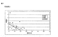
本発明は、添付した図面に関連して示す以下の記載を基により理解され得る。 The invention can be understood on the basis of the following description given with reference to the attached drawings.
本発明の関連で、従ってPCM凝集体を、吸着剤粒子と上記凝集体の混合物が、スペース内に、PSAユニットの操作中の時間に亘って均一に留まるような形状、直径および密度を有するように生成する。 In the context of the present invention, therefore, the PCM agglomerates have a shape, diameter and density such that the adsorbent particles and a mixture of the agglomerates remain uniformly in the space over time during operation of the PSA unit. To generate.
異なる性質を有する粒子の混合物は、媒体が力場、特に振動または衝撃にさらされた際に、複雑な様式で発達し得る準安定状態となることは知られている。 It is known that a mixture of particles having different properties becomes a metastable state that can develop in a complex manner when the medium is exposed to a force field, particularly vibration or shock.
PSAユニットの吸着剤床はガス流にさらされ、この激しさと方向は、ある工程から次の工程へと変化する。これらは、また、バルブの開閉を引き起こす遷移相にもさらされる。 The adsorbent bed of the PSA unit is exposed to a gas stream, and this intensity and direction changes from one process to the next. They are also exposed to a transition phase that causes the valve to open and close.
一般的に、吸着ユニットに入るまたは出ていく少なくとも1種の流れは、圧縮ユニット(コンプレッサまたは真空ポンプ)からもたらされまたは供給し、これは流体に対して可変の振動数の振動および強度を伝える。これらの現象は、粒子の全運動または局所的な運動を生じ、これは、吸着体の形状の寸法決定(dimensioning)の際に考慮に入れる必要がある。 In general, at least one stream entering or exiting the adsorption unit comes from or supplies a compression unit (compressor or vacuum pump), which provides variable frequency vibration and intensity to the fluid. Tell. These phenomena result in total or local motion of the particles, which must be taken into account when dimensioning the adsorbent shape.
例えば、密に詰めるために補うための吸着剤ガードの使用、粒子の摩滅を避けるための最小の区域の決定、異なる性質を有する吸着剤を混合することを避けるためのワイヤーメッシュの使用、または下部に位置する床の上に存在するセラミックビーズの層の使用であって、ガスの循環による動きを防止することを述べることができる。 For example, the use of an adsorbent guard to make up for tight packing, the determination of the smallest area to avoid particle wear, the use of a wire mesh to avoid mixing adsorbents with different properties, or the bottom It can be stated that the use of a layer of ceramic beads present on the floor located at, prevents movement due to gas circulation.
異なる性質を有する粒子の混合物の経時的な変化は、多数のパラメータ、すなわち、密度および形状または粒子の大きさのみならず、特に表面仕上げ、弾性、介在性ガスの存在、湿気、媒体に適用される振幅および振動の振動数等に依存する。 The change over time of a mixture of particles with different properties applies not only to a number of parameters, namely density and shape or particle size, but especially to the surface finish, elasticity, presence of intervening gases, moisture, medium. Depending on the amplitude and frequency of vibration.
従って、異なる性質を有する粒子から成る混合物における変化を予測することは、多くの場合、非常に困難であるか、予測できない。 Therefore, it is often very difficult or unpredictable to predict changes in a mixture of particles having different properties.
これまでのところ吸着剤を用いるユニットの寸法決定の際に払う注意は、一般的に、実証的試験の結果であることになる。 The precautions so far taken when sizing units using adsorbents will generally be the result of empirical tests.
つまり、支持ビーズの2つの連続層の直径の比が、最大限でも2の因数、例えば3/4’’−3/8’’(すなわち、おおよそ18−9mm)、または1/2’’−1/4’’−1/8’’(すなわち、おおよそ12−6−3mm)である。これらの層の位置決めは、最も大きな粒子サイズから最も小さなものへと変化し得るし、逆もまた同様である。 That is, the ratio of the diameters of two successive layers of support beads is at most a factor of 2, eg, 3/4 ″ -3/8 ″ (ie approximately 18-9 mm), or 1/2 ″ − 1/4 "-1/8" (i.e., approximately 12-6-3 mm). The positioning of these layers can vary from the largest particle size to the smallest, and vice versa.
例えば、湿気を防止するために用いられる1.5mmの直径を有する吸着剤を、3mmの支持ビーズ上に直接配置することができる。このことから、吸着乾燥ユニットの典型的な操作条件下では、各直径について2の因数を順守することにより1450kg/m3付近の密度を有する支持ビーズの床の最上層に、約650〜800kg/m3の密度を有する吸着剤を配置することが可能であるということが推論できる。 For example, an adsorbent with a diameter of 1.5 mm used to prevent moisture can be placed directly on 3 mm support beads. From this, under typical operating conditions of the adsorptive drying unit, by adhering to a factor of 2 for each diameter, the top layer of a bed of support beads having a density near 1450 kg / m 3 is about 650-800 kg / It can be deduced that it is possible to arrange an adsorbent with a density of m 3 .
しかしながら、逆の安定性については、従来技術においては何も情報を得ることができず、すなわち、吸着剤の層よりも高い密度を有する支持ビーズであって、吸着剤の層の上に位置するもの、または異なる性質を有する粒子の集団の混合物の考えられる経時的な変化についてである。 However, no information can be obtained about the reverse stability in the prior art, i.e. support beads having a higher density than the adsorbent layer, which lies above the adsorbent layer. Or a possible change over time of a mixture of populations of particles having different properties.
さらに、吸着剤の製造者は、その製造をふるいにかけて、工業的に用いることができる製品を提供する。サンプルから、粒子の単位サイズを測定すること、および目的のグループ、すなわち、集団の少なくとも5%に含まれている最も小さい粒子と最も大きい粒子を取り込むことによることにより、平均直径と比較した直径の差異は、一般に10%付近であることを実現することができる。これらの粒子は球状であり、同じ組成を有するため、これらは勿論のこと同じ密度を有する。 In addition, adsorbent manufacturers screen their manufacture to provide products that can be used industrially. By measuring the unit size of the particles from the sample and incorporating the smallest and largest particles in the target group, ie at least 5% of the population, It can be realized that the difference is generally around 10%. Since these particles are spherical and have the same composition, they of course have the same density.
この情報に基づいて、混合物として用いることが所望される吸着剤粒子のものとほぼ等しい密度を有し、および非常に近接した大きさ、すなわち直径で±10%の極大差を有するPCM凝集体を製造する必要があるということは、非常に困難であることが本発明者等に明らかになった。というのは、各製造物は所定のPSAに特有であるばかりでなく、同一のPSAについて、吸着剤の各層に対しても特有である必要があるため、非常に制限的で、特に工業的にあまりにも高価であるためであった。これは、すなわち、ガスが連続的に流通するいくつかの重ねあわされた床または並列させた層を用いる、一般的に複数床プロセスであるためである。 Based on this information, PCM aggregates having a density approximately equal to that of the adsorbent particles desired to be used as a mixture and having a very close size, i.e., a maximum difference of ± 10% in diameter. It became clear to the present inventors that it was very difficult to manufacture. Because each product must be unique not only for a given PSA, but also for each layer of adsorbent for the same PSA, it is very restrictive, especially industrially. It was because it was too expensive. This is because it is generally a multi-bed process using several stacked beds or layers of parallel gas flow.
従って本発明の発明者等は、この問題に関して得られる情報がないことを考慮に入れて、種々のPSAタイプの方法において用いられる吸着剤と混合するため、すなわち、初期の混合物が長期に亘っておよびスペース内で均質であることを保つために、PCM凝集体が有さなければならない性質を決定するために必要な情報を得るために、特に異なる密度を有する種々の吸着剤および粒子を用いて一連の試験に着手した。 Therefore, the inventors of the present invention take into account the lack of information available on this problem, to mix with the adsorbents used in the various PSA type processes, i.e. the initial mixture is long term. And using various adsorbents and particles with different densities to obtain the information necessary to determine the properties that PCM aggregates must have in order to remain homogeneous in space A series of tests was undertaken.
アプローチは、まず、工業プロセスの作用の代表的なものであるために、吸着剤とPCM凝集体の混合物に適用するための振動(振動数、振幅)の形態を決定することからなる。 The approach first consists in determining the form of vibration (frequency, amplitude) to apply to the adsorbent and PCM agglomerate mixture, since it is representative of the action of industrial processes.
系における変化はこれらのパラメータに依存するため、この点は重要である。同一の初期混合物について、振動の種類に依存して、得ることができることが認められる:
平衡が長期に亘り安定であり、すなわち、不安定な混合物が、その初期段階において残存する領域(振動数/振幅)、および
最も大きい粒子が表面に上がる領域。この効果は、「ブラジルナッツ効果」として知られる、
最も大きい粒子が床に沈む、この効果は、「逆ブラジルナッツ効果」と呼ばれる。
This is important because changes in the system depend on these parameters. It can be seen that the same initial mixture can be obtained, depending on the type of vibration:
The region where the equilibrium is stable over time, ie where the unstable mixture remains in its early stages (frequency / amplitude) and the region where the largest particles rise to the surface. This effect is known as the “Brazilian nut effect”
This effect, where the largest particles sink to the floor, is called the “reverse Brazil nut effect”.
上記した全ての実験を、フリッチェ(Fritsch)ラボラトリー篩振盪機、および120mmの長さ、80mmの幅、および80mmの高さを有する透明な平行6面体のコンテナを用いて行った。 All the experiments described above were carried out using a Fritsch laboratory sieve shaker and a transparent parallelepiped container having a length of 120 mm, a width of 80 mm and a height of 80 mm.
工業的ユニットにおいてなされる代表的な調節による篩振盪機の調節の検討は、
粒子の床の自由表面、寸法決定条件下での吸着剤の外観、すなわち、磨耗を生じることなく許容されるガスの最大循環速度におけるものについての視覚的な再現すること、および
この調節をもってして、工業的に直接重ね合わされた異なる性質の吸着剤床(すなわち、分離メッシュを用いない)は事実上安定であること、および逆に言うと、経験から、分離メッシュを必要とする系は、2つの層を分離メッシュを用いることなくぴったりと重ね合わせた際に、振動の効果に基づく粒子の混合をもたらすことを検証すること
から成った。
Examining the adjustment of sieve shakers with typical adjustments made in industrial units,
With a free reproduction of the bed of particles, the appearance of the adsorbent under sizing conditions, i.e. a visual reproduction of what is at the maximum circulation rate of gas allowed without causing wear, and with this adjustment , Industrially directly superimposed adsorbent beds of different properties (ie, without the use of a separation mesh) are virtually stable, and conversely, from experience, systems that require a separation mesh are 2 It consisted of verifying that when two layers were closely overlapped without the use of a separating mesh, it resulted in particle mixing based on the effects of vibration.
吸着体の最小の直径についての研究、従って、最大限許容される比率のものは、投資によるその影響を考慮に入れつつ、吸着による精製のためのユニットの寸法決定において重要なポイントの中の1つである。吸着床の重量および床の中でのガスの循環により引き起こされる圧力損失を含む実験式の設定を、本発明者等により、種々の吸着剤および種々のガス循環条件を用いた試験から予め行なった。 A study on the minimum diameter of the adsorbent, and therefore the maximum allowable ratio, is one of the important points in sizing the unit for purification by adsorption, taking into account its impact on investment. One. The empirical formula including the weight of the adsorbent bed and the pressure loss caused by the circulation of gas in the bed was preliminarily performed by the inventors from tests using various adsorbents and various gas circulation conditions. .
これらの試験の間、粒子が移動し、振り混ざってダスト(磨耗)を生じ始める最大速度に近づくことは、床の水平な自由表面におけるある数の粒子の振動により示され、ここで粒子のいかなる移動もない。上限の速度は、表面におけるほぼ5%の粒子がこれらの振動に供される場合であることが一般的に認められる。壁においてある程度非常に限定され局在化した場所におけるものは別として、より下層の粒子は動かないままである。 During these tests, approaching the maximum speed at which the particles begin to move and shake to create dust (abrasion) is indicated by the vibration of a number of particles on the horizontal free surface of the floor, where any of the particles There is no movement. It is generally accepted that the upper speed limit is when approximately 5% of the particles on the surface are subjected to these vibrations. Apart from some very limited and localized locations in the wall, the underlying particles remain stationary.
篩振盪機の操作パラメータを決定し、および上記した通りこれらを実証するために、まず第一に吸着剤を使用した後、種々のガス精製または製造プロセスに対応する種々の一組の床を用いた。 In order to determine the operating parameters of the sieve shaker and to demonstrate them as described above, the adsorbent is used first, followed by different sets of beds corresponding to different gas purification or production processes. It was.
特に、まず最初は合成ガスの精製、または空気分離低温プロセスについて、種々のゼオライトを用いた後に、分離メッシュを用いることのない、ゼオライトを上に有する活性アルミナタイプの吸着剤床の重ね合わせを用いた。 In particular, for synthesis gas purification or air separation cryogenic processes, the use of various zeolites followed by a stack of activated alumina type adsorbent beds with zeolites on top, without the use of a separation mesh. It was.
用いたゼオライトは、Ceca, UOP and Zeochem により販売されている13Xゼオライトであり、1.5〜3.3mmの直径を有するものであり、活性アルミナは、Engelhard, Porocel, UOP, Axens and Alcan のものであり、おおよそ1.8〜6mmの粒径に相当する。 The zeolite used is a 13X zeolite sold by Ceca, UOP and Zeochem, having a diameter of 1.5 to 3.3 mm, and the activated alumina is from Engelhard, Porocel, UOP, Axens and Alcan Which corresponds to a particle size of approximately 1.8 to 6 mm.
行なった一連の試験は、永続的な振動条件、50Hzの振動数、およびおおよそ0.15〜0.5mmの振幅を結果として導き、これは取り入れられた上部に配置された吸着剤に依存する。 A series of tests performed resulted in a permanent vibration condition, a frequency of 50 Hz, and an amplitude of approximately 0.15 to 0.5 mm, depending on the adsorbent placed on top.
2〜3mmの直径、および約600kg/m3の密度を有する粒子について、用いた振幅は約0.3mmであった。これは、より小さな粒子については減少し、より大きな粒子については増加し、50Hzの永続的な振動数については、その基準は、上部の層について上記した状態(粒子の移動を伴わない局部的な振動)を得ることだった。 For particles having a diameter of 2-3 mm and a density of about 600 kg / m 3 , the amplitude used was about 0.3 mm. This decreases for smaller particles, increases for larger particles, and for 50 Hz permanent frequency, the criterion is the same as described above for the upper layer (local with no particle movement). Vibration).
以下の試験は、粒子が、このように定義された振動に供された際にも均一なままである混合物を構成する異なる粒子の性質を発見することにある。このタイプの研究を実現することができる、振動数と振幅の推測的な他の組み合わせがあることが観察され得る。用いた様式は、良好な調節をなすことを可能にするために用いられる装置についての1つの可能性に相当する。 The following test consists in finding the properties of the different particles that make up the mixture that remains uniform when subjected to the vibrations thus defined. It can be observed that there are other speculative combinations of frequency and amplitude that can achieve this type of study. The mode used represents one possibility for the device used to make it possible to make good adjustments.
上記した吸着によるガスの精製または分離のための方法において直接的に用いられる吸着剤に加えて、1.5〜10mmの範囲の粒径を有する調整されたガラスビーズ、および数ミリメートルの直径を有する金属ビーズも用いた。 In addition to the adsorbent used directly in the method for purification or separation of gases by adsorption described above, conditioned glass beads having a particle size in the range of 1.5 to 10 mm, and having a diameter of a few millimeters Metal beads were also used.
試験の殆どは、異なる性質を有する2つのタイプの粒子AおよびBを用いる研究的な系から成る。その後に、2つの支配的なパラメータ、すなわち等価な直径および密度のみを維持したが、とは言え特に表面仕上げに依存する挙動における小さな差異を観測した。 Most of the tests consist of an experimental system using two types of particles A and B with different properties. Subsequently, only two dominant parameters were maintained, namely equivalent diameter and density, although a small difference in behavior was observed, especially depending on the surface finish.
従って、本発明に関連して、「直径」という語は、粒子の等価直径を指す。粒子の「等価直径」という語は、同じ比表面積を有する球状のものであり、比表面積は、問題となる粒子の体積に関連する表面積である。 Thus, in the context of the present invention, the term “diameter” refers to the equivalent diameter of the particles. The term “equivalent diameter” of a particle is spherical with the same specific surface area, which is the surface area associated with the volume of the particle in question.
従って、直径dおよび長さlを有するロッドについて、等価直径Deは、
De=6×l×d/(2×d+4×l)
として得られる。
Thus, for a rod having a diameter d and a length l, the equivalent diameter De is
De = 6 × l × d / (2 × d + 4 × l)
As obtained.
d=1のようなペレットについては、等価直径は粒子の直径である。 For pellets such as d = 1, the equivalent diameter is the particle diameter.
一般的に、シリンダタイプの用いた粒子の形状の殆どについて、等価直径は、シリンダの直径の0.75〜1.3倍である。 In general, for most of the cylinder-type particle shapes used, the equivalent diameter is 0.75 to 1.3 times the cylinder diameter.
球状のビーズについては、等価直径はそのままビーズの直径である。 For spherical beads, the equivalent diameter is directly the diameter of the bead.
本質的に球状であるが、その直径が、工業製造プロセスにつきもののばらつきを有しているビーズの集合体について、従来的な定義を用いる:ビーズの集合体の等価直径は、床の同じ体積については、同じ全表面積を与え得る同一のビーズの直径である。特に、直径による分布が測定されている限りは(すなわち、例えば篩い分けにより、または画像処理デバイスから直径Diの種々の割合Xiを測定し、好ましくはiは、十分な正確さを得るために5よりも大きいか5である)、等価直径を式:
1/De=Σi(Xi/Di)
から得る。
For a collection of beads that are spherical in nature but whose diameter varies from one industrial manufacturing process to another, the conventional definition is used: the equivalent diameter of a collection of beads is for the same volume of the bed Is the diameter of the same bead that can give the same total surface area. In particular, as long as the distribution by diameter is being measured (ie by measuring various proportions Xi of the diameter Di, for example by sieving or from an image processing device, preferably i is 5 to obtain sufficient accuracy. Greater than or equal to 5), the equivalent diameter is the formula:
1 / De = Σi (Xi / Di)
Get from.
砕いた吸着剤については、特に、ある種の活性炭を見出すことができ、粒子が球体へと同化し、その直径分布は篩い分けにより測定された後、上記の計算式を適用した形状を用いた。 For the crushed adsorbents, in particular, some kind of activated carbon can be found, the particles are assimilated into spheres, and the diameter distribution is measured by sieving, then the shape applying the above formula was used. .
さらに、本発明に関連して、「密度」という語は、粒子の床の密度を意味するものと理解される。充填法により、密度は数%だけ変化し得る。一般的に、本発明による試験において、下層の密度は緻密な充填に対応する。というのは、透明コンテナを、水平な自由表面を形成するために第1のタイプの粒子を充填した後に振動させ、一方で、粒子の第2の層の堆積を漏斗を通して行い、この端部は、適所に既にある層の高さの真上であったためである。このようにして、この第2の層の初期充填は「ゆるやかな」タイプであるが、稼動中の篩振盪機により起こる振動が、緻密な充填をもたらす。 Furthermore, in the context of the present invention, the term “density” is understood to mean the density of the bed of particles. Depending on the filling method, the density can vary by a few percent. In general, in the test according to the invention, the density of the lower layer corresponds to a dense packing. This is because the transparent container is vibrated after being filled with the first type of particles to form a horizontal free surface, while the second layer of particles is deposited through the funnel, this end being This is because it was directly above the height of the layer already in place. In this way, the initial filling of this second layer is of the “loose” type, but the vibrations caused by the operating sieve shaker result in a dense filling.
工業的なユニットの充填中、「シャワー」を生じるように、バッフル上に十分な高さから吸着剤粒子を落下させることにより得られる、緻密なタイプの充填を一般的に行なう。 During the filling of industrial units, a dense type of filling, generally obtained by dropping adsorbent particles from a sufficient height on the baffle to produce a “shower”, is generally performed.
これらの理由のため、また詰まった密度(緻密な充填)の獲得として、得ることができる最大密度であり、嵩密度よりも特により再現可能であり、詰めた密度については、以下に示す表および式において言及し、本記載においては「密度」という語により簡単に示し得るため、よりよく定義される。 For these reasons, and also as the acquisition of packed density (dense packing), it is the maximum density that can be obtained, and is particularly more reproducible than the bulk density. It is better defined because it is referred to in the formula and can be simply indicated by the term “density” in this description.
各粒子が、理論上、その最も良い位置を見出すことができるように、粒子をメスシリンダにゆっくりと充填することによりこの密度は得られる。実際は、シリンダの上部においては、目の粗い篩いを用いることにより、粒子のシャワーを行なう。種々の技法を、同様の結果を得るために用いることができる。全ての測定および試験を、実際に、5%未満または5%の吸着された含水量を伴う、予め再生した吸着剤上で行った。 This density is obtained by slowly packing the particles into a graduated cylinder so that each particle can theoretically find its best position. In practice, the particles are showered at the top of the cylinder by using a coarse sieve. Various techniques can be used to obtain similar results. All measurements and tests were actually performed on pre-regenerated adsorbents with an adsorbed water content of less than 5% or 5%.
より特には、試験を上記した通り、30〜50mmの高さに亘って粒子Aの第1の層を堆積した後、ほぼ同じ高さ、すなわち約30〜50mmに渡って粒子Bの第2の層を堆積して、コンテナを殆ど充填する。 More particularly, as described above, after depositing the first layer of particles A over a height of 30-50 mm, the second of particles B over approximately the same height, ie, about 30-50 mm. Deposit a layer and almost fill the container.
最初に、試験を、粒子の層を体系的に逆さにすることにより行なった。 Initially, testing was performed by systematically inverting the layer of particles.
観察は、壁における、工業用吸着体に典型的でないコーナー効果を避けるためにコンテナの中央部分における浸入に関して、および表面または底における他の種のビーズの外観またはそれ以外に関した。 The observations related to the penetration in the middle part of the container to avoid corner effects that are not typical for industrial adsorbents in the walls and to the appearance of other types of beads or otherwise on the surface or bottom.
コンテナを振動させながら、吸着剤の壁におけるおよび上面における観察を行なうことができ、その底部での観察を、コンテナを注意深く持ち上げることにより行なう。周縁現象、すなわち壁における層の相互貫入を、試験中、「無視可能」、「容認可能」、または「容認不可」として、貫入が観察されないかまたはわずかな貫入が観察されるか否かにより認定し、他の種の粒子の最大2または3層に相当するもの、またはコンテナの底部に到達するより大きな旋回貫入(evolutive penetration)に限られる。 Observations at the adsorbent wall and at the top surface can be made while vibrating the container, and observation at the bottom is made by carefully lifting the container. Peripheral phenomena, i.e. interpenetration of layers in the wall, identified as `` ignorable '', `` acceptable '' or `` unacceptable '' during the test by whether no penetration is observed or slight penetration is observed However, it is limited to the equivalent of up to two or three layers of other species of particles, or larger evolutive penetration reaching the bottom of the container.
壁における貫入現象が数十デシメータ、またはなお一般的に数メータの直径を有する吸着剤について容認でき、この現象は、適当な場所で、予定するPSA法において容認されないであろう分離を引き起こす微粒子媒体の一部が成長することをもたらすことで終わったことを示すことができる。壁における移動のこの現象は、文献において、場合によりさらに対流移動を最終的に生じるとして知られ、評されている。 Fine particle media that cause wall penetration phenomena for adsorbents with diameters of tens of decimeters, or even generally several meters, which cause separations that would not be acceptable in the intended PSA process at the appropriate location You can show that part of it ended up bringing about growth. This phenomenon of movement in the wall is known and described in the literature as possibly resulting in further convective movement.
コンテナの自由表面におけるまたは底部における他の種のビーズの外観は、明らかに、「容認不可」として示された。 The appearance of other types of beads at the free surface or at the bottom of the container was clearly indicated as “unacceptable”.
振動に供された際に、層AおよびB、さらにまたBおよびAは互いに混合せず、すなわち、種々の基準が2つの配置において容認可能かどうか、粒子AおよびBのいずれもの混合物は安定なままであるか否かを視覚的に続いて立証した。この結果を、6つの観測できる表面の視覚的実験により得た。 When subjected to vibrations, layers A and B, and also B and A, do not mix with each other, i.e., if the various criteria are acceptable in the two configurations, any mixture of particles A and B is stable. It was subsequently verified visually whether or not. This result was obtained by visual observation of six observable surfaces.
他の重要な観察は、系の動力学は、特に他の床を通じた粒子の落下運動または上昇運動が遅い可能性があるか否かを確認することから成った。興味深いケースについて、すなわち、所望の平衡制限に近いものについて、コンテナは1時間を超えて篩振盪機上に保たれた後、上層をスクレーパを用いて静かに移動させて、下層からの粒子が、自由表面上に現れようとしていないことを確実にした。 Another important observation consisted in confirming whether the dynamics of the system could be slow, especially the falling or rising motion of the particles through other beds. For interesting cases, i.e. close to the desired equilibrium limit, after the container has been kept on the sieve shaker for more than 1 hour, the upper layer is gently moved using a scraper, and particles from the lower layer are Ensured that it was not about to appear on the free surface.
最後の興味深い観察は、工業用ユニットを代表するものとして決定された2つのもの、すなわち粒子および振動モードの選択により(生じ得る種々のケースを無視して)実質的に1を超える比、すなわち、最も大きい直径の最も小さいものに対する比、最も高い密度の最も低い密度に対する比)、試験を直径と密度の比により特徴づける際に、大きくて軽い粒子の上に小さくて重い粒子で構成されている系が、最も重要な系であった。 The last interesting observation is that two determined to be representative of industrial units, a ratio substantially greater than 1 (ignoring the various cases that can occur) due to the choice of particle and vibration mode, ie The ratio of the largest diameter to the smallest one, the ratio of the highest density to the lowest density), consisting of small and heavy particles on top of large and light particles when characterizing the test by the ratio of diameter to density The system was the most important system.
重要な状況、より大きくて軽い粒子の上により小さくて重い粒子に対応する粒子の30のまたは2成分の系の場合、安定な配置と粒子の分離をもたらす発展的(evolutive)な配置の間の境界を定義することができた。 In an important situation, in the case of a 30 or two-component system of particles corresponding to smaller and heavier particles on larger and lighter particles, between an evolutive arrangement that leads to a stable arrangement and separation of the particles. The boundary could be defined.
添付した図1は、x軸では、粒子の直径の比(低い層の粒子の等価直径/上層の粒子のものの直径)を、y軸では、2つのビーズの重装かさ密度(上部の床の密度/下部の床の密度)により得られた結果を示す。 The attached FIG. 1 shows the ratio of the diameter of the particles (equivalent diameter of the lower layer particles / the diameter of the upper layer particles) on the x axis, and the bulk density of the two beads (on the upper floor) on the y axis. Density / lower floor density).
図1において、異なる密度比については安定な領域があり、すなわち、破線(−−−)で示した直線の下に位置する領域であり、PSA法において用いられる吸着剤について従来技術に記載されたものよりも著しく大きいものであることを確認することができる。 In FIG. 1, there is a stable region for different density ratios, that is, a region located under a straight line indicated by a broken line (---), and the adsorbent used in the PSA method has been described in the prior art. It can be confirmed that it is remarkably larger than that.
さらに、実線(―)で示される直線は、ある種のサイクルにおいて現れることがあるある種の制限を除外し、従って、一過性の工程の間も含む、PSA法の良好な操作を確実にすることの安全な保証をなし得る優先的な領域に対応する。 In addition, the straight line indicated by the solid line (-) excludes certain limitations that may appear in certain cycles, thus ensuring good operation of the PSA process, even during transient processes. Addressing priority areas where safe assurance can be made.
以下の表は、図1を証明するために用いられる種々の粒子の性質を示す。

一連の試験を行なった後に、安定な決定した領域内にある粒子の混合物は、PSA適用の時間に亘って均一なままであり得る。 After performing a series of tests, the mixture of particles that are within a stable determined region may remain uniform over the time of PSA application.
密度(R密度)の比が、等価直径(R直径)の比の関数として定義される値よりも低いままである限り、比較的異なる密度の粒子を用いても、PSAの操作条件下では均一性を保ったままである混合物を製造することができることが観察される。 As long as the ratio of density (R density) remains below the value defined as a function of the ratio of equivalent diameter (R diameter), even with relatively different density particles, it is uniform under the operating conditions of the PSA. It is observed that a mixture can be produced that retains its properties.
単純な関係、すなわち図1のカーブを採用することにより、安定な領域にあることを可能にする密度の比が、直径の比の関数であること、すなわち:
R密度≦5.5−(2.R直径)(破線カーブ)
であり、好ましくは、より安定な様式は、
R密度≦5−(2.R直径)(実線カーブ)
であることを示すことができる。
By adopting a simple relationship, ie the curve of FIG. 1, the density ratio that makes it possible to be in a stable region is a function of the diameter ratio, ie:
R density ≦ 5.5 (2.R diameter) (dashed curve)
Preferably, the more stable mode is
R density ≤ 5- (2. R diameter) (solid curve)
It can be shown that.
前もって示した通り、R密度は最も重い材料の密度の最も軽いものの密度に対する比であり、R直径は、最も大きい粒子の等価直径の、最も小さい粒子の等価直径に対する比である。 As previously indicated, R density is the ratio of the density of the heaviest material to the density of the lightest, and the R diameter is the ratio of the equivalent diameter of the largest particle to the equivalent diameter of the smallest particle.
例えば、2mmの直径と800kg/m3の密度を有する凝集体との混合物としての3mmの直径と400kg/m3の直径を有する吸着剤の場合において、R直径は、吸着剤の直径の凝集体の直径に対する比(すなわち、3/2=1.5)であり、一方、R密度は、凝集体の密度の吸着剤の密度に対する比(すなわち、800/400=2)である。 For example, in the case of an adsorbent having a diameter of 3 mm and a diameter of 400 kg / m 3 as a mixture of an aggregate having a diameter of 2 mm and a density of 800 kg / m 3 , the R diameter is an aggregate of the diameter of the adsorbent. The ratio of the density to the diameter of the adsorbent (ie 800/400 = 2), while the R density is the ratio of the aggregate density to the adsorbent density (ie 800/400 = 2).
このことは、吸着剤が、その性質として、2mmの直径と500kg/m3の密度を有する場合には、PCM凝集体は、例えば、
同一の等価直径(R直径=1)を有するために、約145kg/m3〜1750kg/m3の密度、好ましくは約170kg/m3〜1500kg/m3の密度を有し、;および
1mmまたは4mmの等価直径(R直径=2)を有するためには、最大限で、約335kg/m3〜750/m3の密度を有する
ということを意味する。
This means that if the adsorbent has, as a property, a diameter of 2 mm and a density of 500 kg / m 3 , the PCM aggregate is
In order to have the same equivalent diameter (R diameter = 1), a density of about 145kg / m 3 ~1750kg / m 3 , preferably a density of about 170kg / m 3 ~1500kg / m 3 ,; and 1mm or To have an equivalent diameter of 4 mm (R diameter = 2), it means that it has a maximum density of about 335 kg / m 3 to 750 / m 3 .
殆どの工業用PSAユニットは、およそ0.8mm〜3.2mmの範囲の等価直径と、最も軽いもので約400kg/m3〜最も重いもので約800kg/m 3 の範囲の密度を有する吸着剤を用い、例えば活性アルミナ、交換ゼオライト等である。 Most industrial PSA units have an equivalent diameter in the range of approximately 0.8 mm to 3.2 mm and an adsorbent having a density in the range of about 400 kg / m 3 at the lightest to about 800 kg / m 3 at the heaviest. For example, activated alumina, exchanged zeolite and the like.
1.6mmの直径と540〜600kg/m3の床密度を有するPCM凝集体は、非常に幅広く用いることができ、従って、魅力的なコストで大量生産することができ得る粒子を構成し得ることを理解することができる。 PCM agglomerates having a diameter of 1.6 mm and a bed density of 540-600 kg / m 3 can be used very widely and thus constitute particles that can be mass produced at attractive costs Can understand.
より特には、大きな工業的な複合施設に設置される、大型の工業用PSAユニットは、一般的に、1.6〜3.3mmの範囲に亘る直径と、最も軽いもので約400kg/m3〜最も重いもので約800kg/m3の範囲に亘る密度を有する吸着剤を用いる。全てのこれらのユニットについて、2〜3mmの等価直径と、500〜600kg/m3の密度を有する凝集体が安定であることを理解することができる。 More particularly, large industrial PSA units installed in large industrial complexes generally have diameters ranging from 1.6 to 3.3 mm and the lightest at about 400 kg / m 3. Use the adsorbent that is the heaviest and has a density ranging from about 800 kg / m 3 . It can be seen that for all these units, aggregates having an equivalent diameter of 2-3 mm and a density of 500-600 kg / m 3 are stable.
反対に、迅速なPSAユニットまたはRPSAユニット、例えば医療用酸素濃縮器または発生器、および燃料電池のためのH2PSAユニットは、一般的に、より小さな直径、一般的には0.8〜1.6mmを有する吸着剤を用いる。従って、1〜1.5mmの等価直径と、500〜600kg/m3の密度を有する凝集体は、これらの方法の大部分を対象とする。 Conversely, rapid PSA units or RPSA units, such as medical oxygen concentrators or generators, and H 2 PSA units for fuel cells are typically smaller diameters, typically 0.8-1 Adsorbent with 6 mm is used. Thus, aggregates having an equivalent diameter of 1 to 1.5 mm and a density of 500 to 600 kg / m 3 are targeted for most of these methods.
本発明による吸着剤の粒子およびPCM凝集体間の混合は、例えば、ユニットの充填方法についてまたは充填中に用いられる比に従って、吸着剤をバレルに詰めるまたは入れる際に行われ得る。 The mixing between the adsorbent particles and the PCM aggregates according to the invention can take place when packing or putting the adsorbent into the barrel, for example according to the unit filling method or according to the ratio used during filling.
実施するのにより容易であるため、最初の解決法を好ましくは用いる。実験から、通常条件下で行われる輸送は、ユニットの現実の操作と比較して、吸着剤/PCM混合物についてより重要な工程を構成しない。例えば大きさに応じた分離は観察されない。吸着剤の充填を、それ自身が種々の粒子の分離を引き起こさないように適合させ得る。 The first solution is preferably used because it is easier to implement. From experiments, transport performed under normal conditions does not constitute a more important process for adsorbent / PCM mixtures compared to the actual operation of the unit. For example, separation according to size is not observed. The packing of the adsorbent can be adapted so that it does not itself cause the separation of the various particles.
全てのケースにおいて、この凝集体が、前に説明した通りのヒートシンクとして作用し得ることが望ましい。 In all cases, it is desirable that this agglomerate can act as a heat sink as previously described.
一般的に0.2W/(m.K)のオーダーの、マイクロカプセル封入されたPCMの熱伝導率は、これらのマイクロカプセルからのみ形成されるミリメーターサイズの凝集体に、PSAの迅速なサイクル、さらにはRPSAタイプのものに適合する熱伝導率を与え得るには不十分であり得る。 The thermal conductivity of microencapsulated PCM, typically on the order of 0.2 W / (m.K), allows for rapid cycling of PSA into millimeter-sized aggregates formed only from these microcapsules. Furthermore, it may be insufficient to provide a thermal conductivity compatible with that of the RPSA type.
この点を、メラミン−ホルムアルデヒドカプセル中にマイクロカプセル封入されたパラフィン系PCMを用いたペレット化試験を行なうことにより確認した。 This point was confirmed by conducting a pelletization test using paraffinic PCM microencapsulated in melamine-formaldehyde capsules.
マイクロカプセル化したPCM粉末を、ペレット成形機のコンパートメント内に配置し、種々の圧力を、すなわち2〜1800barの圧力をかけた。 The microencapsulated PCM powder was placed in the pelletizer compartment and various pressures were applied, i.e., 2 to 1800 bar.
得られたペレットは4〜7mmの厚さであり、この厚さは、コンパートメント中に導入した粉末の量により制御可能であり、直径は2cmであった。得られたペレットの殆どを取扱うことができ、またこの形態で、吸着体に導入することができた。得られたペレットの密度は500〜1000kg/m3であり、一方PCMマイクロカプセル粉末の密度は、約300〜400kg/cm3であった。 The resulting pellets were 4-7 mm thick and this thickness was controllable by the amount of powder introduced into the compartment and the diameter was 2 cm. Most of the resulting pellets could be handled and in this form could be introduced into the adsorbent. The density of the resulting pellets was 500-1000 kg / m 3 , while the density of the PCM microcapsule powder was about 300-400 kg / cm 3 .
熱伝導率は成形圧力により比較的わずかに変化し、サンプルによって、0.1〜0.3W/(m.K)であった。このような値は、既知の大多数のPSAユニットにおける、例えば数mmの厚さを有する平板におけるPCM凝集体についての、これら凝集体の使用を不可能にし、大多数のPSA法に時間的に適合する特徴的な熱伝導率を得るためには、熱伝導率は0.5W/(m.K)よりも高い必要がある。 The thermal conductivity changed relatively slightly depending on the molding pressure, and was 0.1 to 0.3 W / (m · K) depending on the sample. Such a value makes it impossible to use these aggregates in the majority of known PSA units, for example for PCM aggregates in flat plates with a thickness of a few mm, and in time for the majority of PSA processes. In order to obtain a suitable characteristic thermal conductivity, the thermal conductivity needs to be higher than 0.5 W / (mK).
本発明の1つの改善によれば、従って、PCM凝集体の熱伝導率を、PSAまたはRPSA法のサイクル時間に適した値にまで上昇させる。 According to one improvement of the invention, therefore, the thermal conductivity of the PCM aggregate is increased to a value suitable for the cycle time of the PSA or RPSA process.
本発明によるPCM凝集体の熱伝導率を、測定中に、決してPCMが相を変えないような温度で測定する。一般的に、PCMは、最低相変化温度と最高相変化温度の間の温度領域において相を変える。 The thermal conductivity of the PCM aggregates according to the invention is measured at a temperature such that the PCM never changes phase during the measurement. In general, PCM changes phase in a temperature region between the lowest phase change temperature and the highest phase change temperature.
本発明によれば、PCM凝集体の熱伝導率を、最高相変化温度以上、好ましくは最高相変化温度の少なくとも5℃上、好ましくは、最高相変化温度の5〜20℃上の温度で測定する。 According to the invention, the thermal conductivity of the PCM aggregate is measured at a temperature above the highest phase change temperature, preferably at least 5 ° C. above the highest phase change temperature, preferably 5-20 ° C. above the highest phase change temperature. To do.
このようにして、凝集体の熱伝導率の測定中に相変化に直面することがないように保証される。というのは、凝集体の熱伝導率の測定について考えられる方法の1つは、例えば、Gustafsson SE et al., J Phys D: Appl Phys 12, 1411 (1979) or Gustafsson SE et al. J Phys D: Appl Phys 19, p. 727 (1986) または SE A 461,797, US-A-5,044,767 or Gustafsson SE. Rev. Sci.; Instrum. 62, 797 (1991) に記載されている「ホットディスク」プロトコルに従って、凝集体にエネルギーを供給することを含むためである。
In this way it is ensured that no phase change is encountered during the measurement of the thermal conductivity of the agglomerates. This is because one possible method for measuring the thermal conductivity of aggregates is, for example, Gustafsson SE et al., J Phys D:
「ホットディスク」法は1つの可能性のある方法であるが、PCM凝集体の熱伝導率を、従来技術において知られるいずれもの他の方法により測定することができる。 The “hot disk” method is one possible method, but the thermal conductivity of PCM aggregates can be measured by any other method known in the prior art.
凝集体の形状そのままが、このタイプの特性評価に直接役立つことができ、例えば、凝集体が板状体、押出物若しくはペレットの形態にある場合であり、また他方では、その形状はこれを直接的に特性評価できないこともあり得る。 The shape of the agglomerate can directly serve for this type of characterization, for example when the agglomerate is in the form of a plate, extrudate or pellet, and on the other hand the shape directly Characteristic evaluation may not be possible.
後者のケースにおいて、凝集体と同じ性質を有し、その形状がその特性評価を可能にするサンプルを製造することが可能であり、例えば凝集体のものと同一の配合を有する押出物またはペレットの製造である。 In the latter case, it is possible to produce a sample that has the same properties as the agglomerate and whose shape allows its characterization, e.g. of an extrudate or pellet having the same formulation as that of the agglomerate Is manufacturing.
先に示したとおり、従って、マイクロカプセル封入されたPCMから製造されるPCM凝集体は、大多数のPSA法に時間的に適合する特徴的な熱伝導率を得るために、最後には、改善が所望されるPSA法に適合する熱伝導率であって、実際には0.5W/(m.K)に等しいかこれよりも大きい熱伝導率を有するように設計される。 As indicated above, therefore, PCM aggregates made from microencapsulated PCM are finally improved to obtain a characteristic thermal conductivity that is temporally compatible with most PSA methods. Is designed to have a thermal conductivity compatible with the desired PSA method, which is actually equal to or greater than 0.5 W / (m.K).
PCM凝集体の伝導率を向上させるための第1の方法は、PCMを伝導性材料と組合わせることである。この方法によれば、マイクロカプセル封入されたPCMを、高い熱伝導率のプロモータ(金属または炭素ベースの繊維、粒子、ストリップまたは削り屑)と混合して、改善された熱伝導率を有する複合体を形成する。その際、全体のアセンブリに例えば圧力をかけて、例えばPSA法の迅速なサイクル時間、すなわち30分未満の時間に時間的に適合する特徴的な伝導を有する、プレートまたはペレットのいずれかを得る。 The first way to improve the conductivity of PCM aggregates is to combine PCM with a conductive material. According to this method, a microencapsulated PCM is mixed with a high thermal conductivity promoter (metal or carbon based fibers, particles, strips or shavings) to provide a composite with improved thermal conductivity Form. In doing so, for example, pressure is applied to the entire assembly, resulting in either plates or pellets having characteristic conduction that is temporally compatible with, for example, the rapid cycle time of the PSA process, ie, less than 30 minutes.
従って、種々の他の粉末、例えば銅および銀粉末と混合されたマイクロカプセル封入されたPCMを用いて圧縮試験を行い、添加の目的は、ペレットの熱伝導率を高めることである。0.5〜0.7W/(m.K)の伝導率を、これらの複合ペレットについて測定した。 Thus, compression tests are performed using a variety of other powders, such as microencapsulated PCM mixed with copper and silver powder, the purpose of addition being to increase the thermal conductivity of the pellets. A conductivity of 0.5-0.7 W / (mK) was measured for these composite pellets.
一般的に、熱プロモータまたはバインダとして作用し得るいずれもの材料をPCM粉末に加えることが可能であり、ペレットの機械的性質または熱的性質を改善することができる。 In general, any material that can act as a thermal promoter or binder can be added to the PCM powder to improve the mechanical or thermal properties of the pellets.
PCM凝集体の伝導率を向上させるための他の考えられる手段は、マイクロカプセル封入されたPCMのマイクロカプセルの外表面の少なくとも一部を、少なくとも1種の熱的に伝導性の材料を上記表面に堆積させることによる金属被覆をまず行った後、このように金属被覆したPCMを凝集させることから成る。PCMの金属被覆は、例えば、FR-A-2 474 660 に記載されている。金属被覆を、いくつかのPCMマイクロカプセルについて同時に行なうことができる。 Another possible means for improving the conductivity of PCM aggregates is that at least a part of the outer surface of the microencapsulated PCM microcapsule is replaced with at least one thermally conductive material on the surface. After first metallization by depositing on the PCM, the PCM thus coated is agglomerated. PCM metallization is described, for example, in FR-A-2 474 660. Metal coating can be performed simultaneously on several PCM microcapsules.
好ましくは、マイクロカプセルは、Cu、Ag、Fe、Ni、Pd、Al、Au、またはこれらの金属の少なくとも1種を取り込んだ合金から選択される金属により部分的に被覆されている。 Preferably, the microcapsules are partially coated with a metal selected from Cu, Ag, Fe, Ni, Pd, Al, Au, or an alloy incorporating at least one of these metals.
図2に示される通り、マイクロカプセル封入されたPCMマイクロカプセル1のマイクロカプセルの表面熱伝導率を高めるために、表面、またはPCM4を含有するこれら小球体1の殻3の金属被覆2を行い、改善された熱伝導率を有する上記マイクロカプセル封入されたPCMの粉末の堆積および圧縮により、小球体から他への凝集体内での熱の効果的な伝導を可能にする伝導性材料の連続的で、非常に密なネットワーク5形成する。
In order to increase the surface thermal conductivity of the microcapsules of the microencapsulated PCM microcapsules 1, as shown in FIG. 2, a
伝導性材料の金属被覆層2は、厚さが100nm未満であり得て、必ずしも連続していない。殻の表面上の金属原子のクラスター6の不連続な堆積は、PCMマイクロカプセルの凝集体の熱伝導率を高めるのに十分である。特に、熱伝導率は材料の全体の量であり、電気伝導率の場合のようにパーコレーション限界基準(percolation threshold criteria)に合致しない。例えば、本発明によるPCM凝集体において、PCMマイクロカプセルの直径は、典型的に、100μm未満、好ましくは50μm未満であり、その結果として、これらマイクロカプセルの表面の一部分が、または限定された数のこれらマイクロカプセルが凝集体内で金属被覆されてない場合には、これら非金属被覆部分は、凝集体の全体の熱伝導に対して非常に低い熱抵抗を示すのみであろう。従って、所望の伝導率に応じて小球体の表面上の伝導性材料の不連続な層のみを堆積し、その結果伝導性材料の消費を節約しながら、熱動力学を制御することを予想することができる。
The
このような手法は、いくつかの利点を有する。特に、
マイクロカプセル化の利点、すなわち取扱いの容易さ、実施のし易さ、詰めたPCMを保ちながら、伝導性PCMマトリクスを得る、
粉末の圧縮後、連続し、非常に密な伝導性ネットワークを備えるように凝集体を製造し、このメッシュは小球体の直径と等しく、すなわち50nm〜50μm、好ましくは1〜10μmであり、
伝導性材料をPCM系に組み込み、
殻に熱導体の役割を与えることにより殻を強化し、従って、系の相変化体積エンタルピー(phase change volume enthalpy)を、熱導体をマイクロカプセル封入したPCMに加え得る系と比べて最適化し、および
金属被覆の程度、凝集体の特徴的な寸法等は、PCMの熱動力学を制御することができる故に、サイクル時間に応じて所定の用途に適合させることができる。
Such an approach has several advantages. In particular,
To obtain a conductive PCM matrix while maintaining the advantages of microencapsulation, ie ease of handling, ease of implementation, and packed PCM,
After the compaction of the powder, agglomerates are produced so as to have a continuous and very dense conductive network, the mesh being equal to the diameter of the spherules, ie 50 nm to 50 μm, preferably 1 to 10 μm,
Incorporating conductive materials into the PCM system,
Strengthening the shell by imparting a role of heat conductor to the shell, thus optimizing the phase change volume enthalpy of the system compared to a system where the heat conductor can be added to microencapsulated PCM, and The degree of metal coating, the characteristic dimensions of the agglomerates, etc. can be adapted to a given application depending on the cycle time because the thermodynamics of the PCM can be controlled.
従って、ポリマー殻の熱伝導率は、制御された金属被覆に基づいて改善される。金属被覆を種々の方法、すなわち、溶射により、溶解金属の溶射により、化学的手段により、または金属粒子を含有する塗料の塗布により行なうことができる。ある種の金属被覆方法(化学的、自己触媒的、または真空蒸着)は、例えば超音波を用いた基材の前処理を必要とすることがある。 Thus, the thermal conductivity of the polymer shell is improved based on a controlled metal coating. The metal coating can be carried out in various ways, ie by spraying, by spraying of molten metal, by chemical means, or by applying a paint containing metal particles. Certain metallization methods (chemical, autocatalytic, or vacuum deposition) may require pretreatment of the substrate using, for example, ultrasound.
有機基材上への溶射によるコーティングの形成は、PCM粒子の殻中に高い熱伝導率を有する粒子を埋め込むための1つの考えられるルートである。このために、例えば金属粉末を含有する高温(〜100℃)ガス流中にマイクロカプセル封入されたPCMを送ることが可能である。高温ガスは、殻の表面を局所的に溶融することを可能にし、これは、金属の粒子をプラスチック中に埋め込むことを可能にする。従って、伝導性材料の層を表面に形成して、金属被覆されたマイクロカプセル封入されたPCMを回収する。プラズマジェットからおよび溶射された材料から生じる大きな熱利得を制限するために、この方法は効率的な冷却手段の使用を必要とする。 The formation of a coating by spraying onto an organic substrate is one possible route for embedding particles with high thermal conductivity in the shell of PCM particles. For this, it is possible to send microencapsulated PCM in a high temperature (˜100 ° C.) gas stream containing, for example, metal powder. The hot gas makes it possible to locally melt the surface of the shell, which makes it possible to embed metal particles in the plastic. Therefore, a layer of conductive material is formed on the surface to recover the metallized microencapsulated PCM. This method requires the use of efficient cooling means in order to limit the large heat gain resulting from the plasma jet and from the sprayed material.
1つの非常によく似たルートは、PCMマイクロカプセル上に溶融金属を溶射することから成る。PCMマイクロカプセルの金属溶射は、十分な速度で溶融粒子を溶射することにより、低温のマイクロカプセルを被覆することから成る。粒子は基材の表面上で、クレープの形をとって凝固する。このコーティングは、多数のこれらクレープの重ね合わせにより得られる。溶射できる材料は、全てのタイプおよび全ての金属または合金を含み、PCMプラスチックマイクロカプセルは、粉末の形態で存在している。このことは、溶射は、非常に柔軟性のある手法であることを意味する。溶射される材料は溶融されている。この溶融操作に必要な熱は、ガス混合物の燃焼により、または電気アークにより供給することができる。火炎温度は、3000℃から20000℃へと変化する。この温度は、得られる層の性質に影響を及ぼす。溶射速度も、堆積物の性質に影響を与えるパラメータである。具体的な予想に合致する堆積物を得ることは、基材の表面に到達する粒子は液体中にあるか、または少なくともペースト状の状態にある必要があり、その速度は、これらを基材に渡って適切な様式で広げるのに十分である必要があり、および最終的には強い付着が、粒子と基材との間に確立する必要があることを暗示している。 One very similar route consists of spraying molten metal onto PCM microcapsules. Metal spraying of PCM microcapsules consists of coating low temperature microcapsules by spraying molten particles at a sufficient rate. The particles solidify in the form of a crepe on the surface of the substrate. This coating is obtained by superposition of a number of these crepes. Materials that can be sprayed include all types and all metals or alloys, and PCM plastic microcapsules exist in powder form. This means that spraying is a very flexible technique. The material to be sprayed is melted. The heat required for this melting operation can be supplied by combustion of the gas mixture or by an electric arc. The flame temperature varies from 3000 ° C. to 20000 ° C. This temperature affects the properties of the resulting layer. Thermal spray rate is also a parameter that affects the nature of the deposit. In order to obtain deposits that meet specific expectations, the particles that reach the surface of the substrate must be in a liquid or at least in a pasty state, the speed of which will be It implies that it needs to be sufficient to spread in a proper manner across and ultimately a strong adhesion needs to be established between the particles and the substrate.
習慣的に用いられる化学的な金属被覆プロセスは、表面調製、続く溶液中に存在する電子ドナーとの触媒反応による金属の還元から成る。これは、3つの必須段階:表面の制御された粗さ、例えば金属形態にあるパラジウムにより生じる活性化、および実際の金属被覆中の化学反応について固有の水素の脱気に依存する。 The customary chemical metallization process consists of surface preparation followed by reduction of the metal by catalysis with an electron donor present in the solution. This relies on three essential steps: controlled roughness of the surface, such as activation caused by palladium in metal form, and the degassing of hydrogen inherent in the chemical reaction in the actual metal coating.
強力な超音波によりもたらされる固有の撹拌を用いる新規の処理ルートが近年開発された。サンプルを高い振幅の音響振動に供することが重要であり、これは、コーティングされる基材の表面におけるキャビテーションバブルの非対称の内破を引き起こす。つまり、方法の性質または反応順序のいずれをも改変することなく、有益な効果が一定の条件下で観察される。いくつかのパラメータをまず研究し、その効果を、堆積速度、付着レベルおよび内部応力レベルに関して測定した。反応順序(超音波照射の時期および時間の選択)、出力、および超音波の周波数が重要である。活性化段階中での超音波の提供は、コロイド状パラジウムの凝集体のパラジウム金属へのより良い分解を可能とし、従って、高周波数および高出力振動下での核生成部位の密度を高める。5ワットの超音波照射を、銅めっきプロセスの開始時に与えた際に、基材に対するコーティングの付着の約30%の改善、およびその耐用年数の十分な延長が観察される。超音波を用い、コーティングの残留応力レベルにおける低下が観察される際に、第1の金属層のより良い機械的な固定が生じる。 New processing routes have been developed in recent years that use inherent agitation provided by powerful ultrasound. It is important to subject the sample to high amplitude acoustic vibrations, which causes asymmetric implosion of cavitation bubbles at the surface of the substrate to be coated. That is, beneficial effects are observed under certain conditions without altering either the nature of the method or the reaction sequence. Several parameters were first studied and their effects were measured in terms of deposition rate, adhesion level and internal stress level. The reaction sequence (selection of timing and time of ultrasonic irradiation), power, and ultrasonic frequency are important. Providing ultrasound during the activation phase allows for better degradation of colloidal palladium aggregates to palladium metal, thus increasing the density of nucleation sites under high frequency and high power oscillations. When 5 watts of ultrasonic irradiation is applied at the beginning of the copper plating process, an approximately 30% improvement in coating adhesion to the substrate and a sufficient extension of its useful life is observed. Better mechanical fixation of the first metal layer occurs when a drop in the residual stress level of the coating is observed using ultrasound.
断熱材(ポリマー、ガラス、セラミック)の「無電解の」または自己触媒的な金属被覆は他の方法であり、これは、表面の活性化およびコーティングすることについての基材の適性を改善することを目標とする、および金属/基材接触面の長期の安定性を改善することを目的として、特有の表面処理の使用を必要とする。本発明の関連で、PCMマイクロカプセル上へのニッケルのまたは銅の「無電解の」堆積が特に重要であり、この殻は、種々の技術的なポリマーから成り、新規の方法の開発において、実際の金属被覆の前に、一方では基材の表面上への窒素ベースの官能基をグラフトすること(NH3またはN2雰囲気中でのRFプラズマ処理により)を導き、他方では、触媒部位の形成(PdCl2の酸溶液中への官能基化された基材の浸漬を介するパラジウムを含有する種の化学吸着による)に進む。 “Electroless” or autocatalytic metallization of thermal insulation (polymer, glass, ceramic) is another method, which improves the suitability of the substrate for surface activation and coating Requires the use of specific surface treatments with the goal of improving the long-term stability of the metal / substrate interface. In the context of the present invention, the “electroless” deposition of nickel or copper on PCM microcapsules is of particular importance, and this shell is composed of various technical polymers, which are practical in the development of new methods. Prior to the metallization of the substrate, on the one hand it leads to grafting nitrogen-based functional groups onto the surface of the substrate (by RF plasma treatment in NH 3 or N 2 atmosphere), on the other hand, formation of catalytic sites Proceed to (by chemisorption of species containing palladium via immersion of the functionalized substrate in an acid solution of PdCl 2 ).
真空技術を用いた金属コーティングの蒸着は、PCMマイクロカプセルの金属被覆のための有利な代替案を提供する。これらの技術は比較的単純であるという利点、および同一の真空チャンバ中で前処理(プラズマ処理)と蒸着を場合により続けざまに行なうという利点を有する。従って、金属層が蒸着される前に被覆される表面の汚染を回避する。さらに、真空プロセスの結果、材料のかなりの節約を達成することを可能にする非常に薄い膜(nmオーダー)を蒸着することを可能にする。他の興味深い点は、純粋な金属層に加えて、合金(例えばステンレス鋼)も蒸着することができるという事実である。真空技術を用いてプラスチック上への金属コーティング層の順調な堆積および真空蒸着法の柔軟性は、PCMの金属被覆についての新しい展望を開き、ここでは、連続層が完全には必要でないためなおさら、蒸着される層の正確な制御が望まれる。PVD(物理的蒸着法)による2つのタイプの蒸着、蒸発およびスパッタリングがある。これらの2つの方法は、ターゲットから粒子を分離する様式の点において異なる。これらの中でも、蒸着物の一定の性質、プロセスの容易な自動化、および環境の保護を述べることができる。 Deposition of the metal coating using vacuum technology provides an advantageous alternative for metallization of PCM microcapsules. These techniques have the advantage of being relatively simple, and optionally performing pretreatment (plasma treatment) and vapor deposition in the same vacuum chamber. Thus, contamination of the surface to be coated before the metal layer is deposited is avoided. Furthermore, as a result of the vacuum process, it is possible to deposit very thin films (on the order of nm) that make it possible to achieve considerable savings in material. Another interesting point is the fact that in addition to pure metal layers, alloys (eg stainless steel) can also be deposited. The smooth deposition of metal coating layers on plastics using vacuum technology and the flexibility of the vacuum deposition process opens up a new perspective on PCM metallization, especially since a continuous layer is not completely required, Accurate control of the deposited layer is desired. There are two types of deposition by PVD (physical vapor deposition), evaporation and sputtering. These two methods differ in the manner in which the particles are separated from the target. Among these, certain properties of the deposit, easy process automation, and environmental protection can be mentioned.
単純な金属被覆方法は、マイクロカプセル封入されたPCMを、金属粒子を含有する塗料中に分散させることから成る。銅(例えば、CuPro-Cote(登録商標))、ニッケル(Super Shield)、銀(Silver Lining Paint)、または他の伝導性材料を含む市販されている塗料がある。マイクロカプセル封入されたPCMを、撹拌しながらこのような塗料に分散させた後、過剰な塗料を、任意に真空下で、多孔性の媒体(例えばガラスフリット)上でろ過することにより除去する。このようにして得られた金属被覆されたPCMを真空下で、いずれもの微量の溶媒を除くことができる温度で乾燥する。堆積した塗料層の厚さを、分散の撹拌速度、塗料の粘度、塗料中での滞留時間等により制御することができる。回収された過剰な塗料は、他のマイクロカプセル封入されたPCMを金属被覆するために再利用してもよい。 A simple metal coating method consists of dispersing microencapsulated PCM in a paint containing metal particles. There are commercially available paints that include copper (eg, CuPro-Cote®), nickel (Super Shield), silver (Silver Lining Paint), or other conductive materials. After the microencapsulated PCM is dispersed in such a paint with stirring, the excess paint is removed by filtration over a porous medium (eg, glass frit), optionally under vacuum. The metal-coated PCM thus obtained is dried under vacuum at a temperature at which any traces of solvent can be removed. The thickness of the deposited coating layer can be controlled by the stirring speed of dispersion, the viscosity of the coating, the residence time in the coating, and the like. The recovered excess paint may be reused to metallize other microencapsulated PCM.
上に示した2つのタイプの方法の組み合わせ、すなわち機械的および/または熱的役割を有するバインダの添加およびPCMマイクロカプセルの少なくとも部分的な金属被覆は、所望の物理的基準に合致する凝集体を得るために必要であり得る。 The combination of the two types of methods shown above, namely the addition of a binder having a mechanical and / or thermal role and at least partial metallization of the PCM microcapsules results in an agglomeration meeting the desired physical criteria. May be necessary to obtain.
従って、大量に製造されるため安価であるPCMから、吸着剤粒子と直接に混合することができ、PSAユニットの熱動力学を改善することができるのに十分に伝導性であるという物理的特徴を有する凝集体を得ることが可能であることが理解される。 Therefore, the physical characteristics of being sufficiently conductive to be able to mix directly with adsorbent particles from PCM, which is inexpensive because it is manufactured in large quantities, and to improve the thermodynamics of the PSA unit It is understood that it is possible to obtain aggregates having
従って、このことは、このタイプのプロセスの大部分に関し、より特には、H2、O2、N2、COおよびCO2PSAユニットに加えて、限定されない種類で、少なくとも2つのフラクションに合成ガスを分けるためのPSAユニット、窒素を除去することを意図した天然ガスPSAユニット、および炭化水素の混合物を分画するために用いられるPSAユニットに関する。 This is therefore the case for the majority of this type of process, and more particularly, in addition to H 2 , O 2 , N 2 , CO and CO 2 PSA units, the synthesis gas in at least two fractions of a non-limiting type. Relates to a PSA unit for separating, a natural gas PSA unit intended to remove nitrogen, and a PSA unit used to fractionate a mixture of hydrocarbons.
吸着剤に加えられる凝集したPCMの割合は、問題とするPSA法によって変化し、例えば高い吸着の領域においてはより大きく(30%)、重要な吸着する微量の成分であり得る範囲においては、より低いかまたはゼロである。 The proportion of agglomerated PCM added to the adsorbent varies with the PSA method in question, for example, it is larger (30%) in the high adsorption region, and more in the range that can be important adsorbing trace components. Low or zero.
所定の層における均質な混合物が望ましいが、特に、1種の特定の媒体中での流体の流れの一定の混合という事実のため、局所的な不均質は全体の結果には重大な影響を与えないであろう。 A homogeneous mixture in a given layer is desirable, but local inhomogeneities can have a significant impact on the overall result, especially due to the fact of constant mixing of the fluid flow in one particular medium. There will be no.
吸着剤床の全体積に亘ってPCMの均一な分布を有する必要はないことを示し得る。例えば、O2PSA法については、最初にゼオライト床の半分に代えて、PCM凝集体を配置させることもより有利である。 It can be shown that it is not necessary to have a uniform distribution of PCM over the entire volume of the adsorbent bed. For example, for the O 2 PSA process, it is more advantageous to initially place PCM aggregates instead of half of the zeolite bed.
より一般的には、複数床PSA法において、PCM凝集体を単一の床中にのみ、またはこれらの床の1つのほんの一部中に、またはこれらの床の複数のある部分中にのみ導入することができる。 More generally, in a multi-bed PSA process, PCM aggregates are introduced only in a single bed, or in only a portion of one of these beds, or in some portion of these beds. can do.
さらに、所定の領域において、PCM凝集体の分布は厳密に均一でないが、一定の標準偏差に従い得る。 Furthermore, in a given region, the distribution of PCM aggregates is not strictly uniform but can follow a certain standard deviation.
いくつかの連続する吸着床11、12および13を備えるPSAユニットの吸着体10を図3に示す。
An
第1の床11は、例えば活性炭、ゼオライト、シリカゲルまたは活性アルミナの吸着剤粒子と混合されたPCM凝集体を含む、本発明による複合吸着床である。 The first bed 11 is a composite adsorbent bed according to the present invention comprising PCM aggregates mixed with adsorbent particles of, for example, activated carbon, zeolite, silica gel or activated alumina.
第2の床12は、例えば活性炭、ゼオライト、シリカゲルまたは活性アルミナの吸着剤粒子と混合されたPCM凝集体を含む、本発明による複合吸着床である。床11および12におけるPCMの割合は同じでない。
The
第3の床13は、PCM凝集体を含まない吸着床である。
The
ガスGは、吸着工程中、第1の床11および第2の床12、その後第3の床13を続けざまに通過する。
During the adsorption process, the gas G passes through the first bed 11 and the
例
以下の例は、工業的PSA法におけるPCMに基づく複合床の適用の例である。
Example The following example is an example of the application of a composite bed based on PCM in an industrial PSA process.
以下、「流入口」および「流出口」という語は、吸着工程中の吸着体の流入端および流出端を示し、「並流」という表現は、この吸着工程中の吸着体におけるガスの流れの方向を示す一方、「逆流」という語は、ガスの流れの逆方向を示す。 Hereinafter, the terms “inlet” and “outlet” refer to the inflow end and outflow end of the adsorbent during the adsorption process, and the expression “cocurrent” refers to the flow of gas in the adsorbent during this adsorption process. While indicating the direction, the term “back flow” indicates the reverse direction of the gas flow.
例1:H2PSA
H2PSA法は、H2に加えて、CO、CO2、CH4、N2、H2Oおよび炭化水素からの少なくとも1種の分子を含有するガス混合物から、水素を精製することを可能にする。
Example 1: H 2 PSA
H 2 PSA process, in addition to H 2, CO, CO 2, CH 4,
このガス混合物は、例えば、以下の源:水蒸気改質装置またはオートサーマル改質装置、例えば部分酸化反応器、フィッシャー−トロプシュタイプ反応器、天然ガスライン、石油化学プラントまたは精製所のガスネットワークにおけるいずれものラインからの少なくとも1種の源から生じ得る。 This gas mixture can be, for example, any of the following sources: steam reformers or autothermal reformers, such as partial oxidation reactors, Fischer-Tropsch type reactors, natural gas lines, petrochemical plants or refinery gas networks Can come from at least one source from the one line.
H2PSAユニットは、文献 US A 4834780 または US A 4475929 に示される通り、通常複数の吸着体、典型的には3〜25の吸着体を備えており、例えば燃料電池に供給するためには、EP A 1243048 に記載されている通り、5Sm3/h〜300000Sm3/hのH2を生成することができる。 The H 2 PSA unit is usually provided with a plurality of adsorbents, typically 3 to 25 adsorbers, as shown in the literature US A 4834780 or US A 4475929, for example to supply a fuel cell: as described in EP a 1243048, it is possible to generate of H 2 5Sm 3 / h~300000Sm 3 / h.
従来技術において、シーケンスバルブH2PSAユニット、および回転式H2PSAユニットとして知られるユニットがある。 In the prior art, there are units known as sequence valve H 2 PSA units and rotary H 2 PSA units.
処理される混合物を高圧5〜40bar絶対圧、好ましくは10〜35bar絶対圧で少なくとも1つの吸着体中に並流で導入する際、H2PSAサイクルは、少なくとも1つの吸着工程を含む。この工程の間、水素よりも重い分子が吸着され、精製された水素が、吸着体の流出口から回収される。 The H 2 PSA cycle comprises at least one adsorption step when the mixture to be treated is introduced in cocurrent flow into the at least one adsorbent at high pressure 5-40 bar absolute pressure, preferably 10-35 bar absolute pressure. During this step, molecules heavier than hydrogen are adsorbed and purified hydrogen is recovered from the adsorbent outlet.
H2PSAユニットのサイクルの少なくとも1つの他の工程は、異なる初期圧力である2つの吸着体を接触させて、ガスが、より高い圧力の吸着体からより低い圧力の吸着体へと流れる間の平衡工程である。 At least one other step in the cycle of the H 2 PSA unit is in contact with two adsorbents at different initial pressures, while the gas flows from a higher pressure adsorber to a lower pressure adsorber. It is an equilibrium process.
平衡工程の主目的の1つは、H2の収率の向上である。 One of the main purposes of the equilibration step is the improvement of yield H 2.
工程の終わりに2つの吸着体において圧力が実質的に等しくなる場合に平衡は完了し得るし、または工程の終わりに2つの吸着体において圧力が実質的に異なる場合には平衡は部分的であり得る。 Equilibrium can be completed if the pressure is substantially equal at the two adsorbers at the end of the process, or the equilibrium is partial if the pressure is substantially different at the two adsorbers at the end of the process obtain.
H2PSAプロセスのサイクルのさらに他の工程は再生工程であり、この間に吸着体は、低い再生圧力へと逆行して減圧される。 Yet another step in the cycle of the H 2 PSA process is the regeneration step, during which the adsorbent is depressurized back to a low regeneration pressure.
一般的に、H2PSA法の再生圧力は、1〜3barであり、ある種の場合には、この再生圧力がより高い、典型的には3〜9bar、好ましくは5〜7barであってもよい。 In general, the regeneration pressure of the H 2 PSA process is 1 to 3 bar, and in some cases this regeneration pressure is higher, typically 3 to 9 bar, preferably 5 to 7 bar. Good.
未だ吸着されているいくつかのガス分子を脱着する、および排出させることからなる再生工程の目的は、吸着剤の吸着容量を回復することである。 The purpose of the regeneration process, consisting of desorbing and discharging some gas molecules still adsorbed, is to restore the adsorption capacity of the adsorbent.
この工程には、吸着体の流出口において導入され、逆流して流れる溶離ガスによるパージを、部分的にまたは完全に加えてもよい。 This process may be partially or completely purged with the eluent gas introduced at the outlet of the adsorbent and flowing backward.
H2PSAサイクルのさらに他の工程は、再圧縮工程であり、この間、吸着工程を再び行い、続くサイクルを始めることができるような実質的に高い圧力にまで吸着体の圧力を高める。 Yet another step in the H 2 PSA cycle is the recompression step, during which the adsorption step is performed again, increasing the adsorbent pressure to a substantially high pressure so that subsequent cycles can begin.
サイクルの他の考えられる工程は、H2PSAの流入口に向かって再生工程中に排出される数種のガスの再利用から成る。 Another possible step of the cycle consists of recycling several gases that are exhausted during the regeneration process towards the inlet of the H 2 PSA.
再利用の目的は、H2収率を改善するためである。H2プロセスのサイクル時間は1分〜30分、好ましくは5分〜15分である。 The purpose of reuse is to improve H 2 yield. H 2 The process cycle time is 1 minute to 30 minutes, preferably 15 minutes 5 minutes.
それにもかかわらず展開される方法におけるある種のRPSAユニットは、1分未満のサイクル時間を有し、改善された熱伝導率を有する凝集体、例えば燃料電池に関連するH2PSAユニットを必要とする。 Nevertheless, certain RPSA units in the deployed process require aggregate times such as fuel cell related H 2 PSA units with cycle times of less than 1 minute and improved thermal conductivity To do.
例2:O2PSA
O2PSA法は、吸着体の流出口において、空気中に存在する窒素を選択的に吸着することにより、70〜99体積%、好ましくは80〜95体積%の純度において酸素を生成することができる。
Example 2: O 2 PSA
The O 2 PSA method can generate oxygen at a purity of 70 to 99% by volume, preferably 80 to 95% by volume, by selectively adsorbing nitrogen present in the air at the outlet of the adsorbent. it can.
同時に、O2PSA法は、再生工程中、吸着体の流入口において窒素豊富な空気を生成することもできる。O2PSA法を、例えば、
WO A 2003/090903、WO A 2005/028059、US A 5906672 または US A 6793719に記載されている通り、酸素を豊富にしたまたは減少させた呼吸に適した空気を製造するための医療分野において用いられる。酸素豊富な空気を送達する医療用O2PSA法の場合には、ユニットにつき送達される酸素の流速は、典型的には、0.5〜300Sl/分である。いくつかのこれらのPSAユニットは、例えば、WO A 2003/064009、WO A 2004/054493、EP A 1307278 または WO A 02/09848 に記載されている通り携帯できるものであり得る。
飛行における機上車両に酸素豊富な空気を送達するための、機上O2PSAユニットのように航空分野において用いられる。これらのPSAユニットは、しばしばOBOGS(機上酸素発生システム)と呼ばれる。このようなシステムは、例えば、WO A 02/04076、EP A 1400275 または EP A 1374972 に記載されている。
At the same time, the O 2 PSA process can also generate nitrogen-rich air at the adsorbent inlet during the regeneration process. O 2 PSA method, for example,
Used in the medical field to produce oxygen-rich or reduced breathable air as described in WO A 2003/090903, WO A 2005/028059, US A 5906672 or US A 6793719 . In the case of a medical O 2 PSA method that delivers oxygen-enriched air, the oxygen flow rate delivered per unit is typically between 0.5 and 300 Sl / min. Some of these PSA units may be portable as described, for example, in WO A 2003/064009, WO A 2004/054493, EP A 1307278 or WO A 02/09848.
Used in the aviation field like an onboard O 2 PSA unit to deliver oxygen-rich air to an onboard vehicle in flight. These PSA units are often referred to as OBOGS (on-board oxygen generation system). Such systems are described, for example, in WO A 02/04076, EP A 1400275 or EP A 1374972.
これらの最初の2つの用途において、改善された熱伝導率を有するPCM凝集体を必要とするRPSAユニットが重要であり得る。
工業的には、例えば冶金、ガラス産業、養魚業、または水処理において用いられる。
In these first two applications, RPSA units that require PCM aggregates with improved thermal conductivity may be important.
Industrially, for example, it is used in metallurgy, glass industry, fish farming or water treatment.
O2PSAユニットは通常、複数のの吸着体、典型的には、1〜3の吸着体を備え、0.03Sm3/h(例えばO2PSAユニットの場合)〜10000Sm3/hのO2を生成することができる。 The O 2 PSA unit usually comprises a plurality of adsorbents, typically 1-3 adsorbents, with 0.03 Sm 3 / h (eg in the case of O 2 PSA units) -10000 Sm 3 / h O 2. Can be generated.
O2PSAユニットは、一般的に、シーケンスバルブを用いて操作する。しかしながら、小型のPSAユニット(典型的には、例えば医療用O2PSAユニット)については、例えば、EP A 1 235 630、WO A 9828013、WO9901202、EP A 1 355 717、US A 6,488,747、US A 6,311,719 または WO A 05025722 に記載されている通り、回転式O2PSA技術が開発されている。O2PSAサイクルは少なくとも1つの吸着工程を備え、この工程の間に、種々の存在し得る不純物(H2O、CO2、炭化水素等)を取り除くために予め処理され得る空気を少なくとも1つの吸着体中に並流で、1bar絶対圧〜8bar絶対圧、好ましくは1.1bar絶対圧〜6bar絶対圧の高圧で導入する。この工程中、窒素を好ましくは吸着し、酸素豊富なガスを吸着体の流出口において回収する。O2PSAユニットのサイクルの他の考えられる工程は、異なる初期圧力における2つの吸着体を、ガスが、より高い圧力の吸着体からより低い圧力の吸着体へと流れるように接触させる平衡工程である。平衡の主目的の1つは、O2収率の向上である。(工程の終わりに2つの吸着体において圧力が実質的に等しい場合には)平衡は完全であり、(工程の終わりに2つの吸着体において圧力が実質的に異なる場合には)平衡は部分的であり得る。O2PSAユニットのサイクルのさらに他の工程は再生工程であり、この工程中、吸着体は低い再生圧力へと逆行的に減圧される。一般的に、O2PSAユニットの再生圧力は、高い吸着圧力に依存して、200mbar〜1.5barである。なお吸着されているいくつかの窒素分子を脱着させ、排出させることから成る再生工程の目的は、吸着剤の窒素吸着容量を回復することである。この工程は、吸着体の流出口において導入されて、逆流して循環する酸素が豊富である溶離ガスのパージと部分的にまたは完全に結合されて、窒素の分圧を再び低下させる。O2PSAサイクルのさらに他の工程は、再圧縮工程であり、この工程中、吸着体の圧力を実質的に高圧にまで上昇させた後、再び吸着工程を行なうことができ、従って続くサイクルが始まる。再圧縮は、供給空気または酸素リッチなガスを用いて行なうことができる。O2PSA法のサイクル時間は5秒〜5分、好ましくは10秒〜2分である。 O 2 PSA units are generally operated using a sequence valve. However, for small PSA units (typically, for example, medical O 2 PSA units), for example, EP A 1 235 630, WO A 9828013, WO9901202, EP A 1 355 717, US A 6,488,747, US A 6,311,719 Alternatively, rotary O 2 PSA technology has been developed as described in WO A 05025722. The O 2 PSA cycle comprises at least one adsorption step during which at least one air that can be pretreated to remove various possible impurities (H 2 O, CO 2 , hydrocarbons, etc.) is removed. It is introduced into the adsorbent in parallel flow at a high pressure of 1 bar absolute pressure to 8 bar absolute pressure, preferably 1.1 bar absolute pressure to 6 bar absolute pressure. During this process, nitrogen is preferably adsorbed and an oxygen-rich gas is recovered at the outlet of the adsorber. Another possible step in the cycle of the O 2 PSA unit is an equilibration step in which two adsorbers at different initial pressures are brought into contact so that gas flows from a higher pressure adsorber to a lower pressure adsorber. is there. One of the main purposes of equilibration is to improve O 2 yield. The equilibrium is complete (if the pressure is substantially equal at the two adsorbents at the end of the process) and the equilibrium is partial (if the pressure is substantially different at the two adsorbers at the end of the process) It can be. Yet another step in the cycle of the O 2 PSA unit is the regeneration step, during which the adsorbent is depressurized back to a low regeneration pressure. In general, the regeneration pressure of the O 2 PSA unit is between 200 mbar and 1.5 bar, depending on the high adsorption pressure. The purpose of the regeneration process, consisting of desorbing and discharging some of the adsorbed nitrogen molecules, is to restore the nitrogen adsorption capacity of the adsorbent. This process is introduced at the outlet of the adsorber and is partly or completely combined with a purge of oxygen-rich eluent gas circulating in the reverse flow to reduce the partial pressure of nitrogen again. Yet another step of the O 2 PSA cycle is the recompression step, during which the adsorbent pressure can be raised to a substantially high pressure and then the adsorption step can be carried out again, so that the subsequent cycle Begins. Recompression can be performed using feed air or oxygen rich gas. The cycle time of the O 2 PSA method is 5 seconds to 5 minutes, preferably 10 seconds to 2 minutes.
例3:CO2PSA
CO2PSA法は、一方では脱炭酸されたガスを、他方ではCO2豊富なガスを、CO2含有供給ガスから生成することを可能にする。脱炭酸されたガスは、0.1〜15%の残余CO2、好ましくは1〜8%の残余CO2を含む。CO2豊富なガスは、10〜99%のCO2(JP A 2003-001061)、好ましくは50〜96%のCO2を含む。CO2法においては、CO2を吸着して、再生工程中に回収し、吸着工程中に、吸着されない脱炭酸されたガスを吸着体の流出口において回収する。従来技術においては、回転式CO2PSAユニット(US A 6,500,236)が存在し、これについても本発明は適用される。CO2PSAユニットを、400ppm〜80%のCO2、好ましくは5%〜50%のCO2を含有するガスを処理するために用いることができ、および例えば冶金産業において、例えばDRI、Corex、Midrex、HYL、または高炉プロセス(US A 6,562,103、US A 5,582,029、US A 5,858,057、US A 5,676,732)から生じるガスの脱炭酸のために、紙産業において、石灰産業において、セメント産業において、発電所において(JP 2003-001061)、IGCCプロセスにおいて(EP A 1142623、US A 5,582,029)、天然ガスの処理若しくは天然バイオガスの処理において、または閉じられた媒体を脱炭酸するため、例えば潜水艦または潜水において適用することができる。CO2PSAユニットは、通常、複数の吸着体、典型的には1〜15の吸着体(JP A 2000-354726)を備える。CO2PSAサイクルは、少なくとも1つの吸着工程を備え、この工程中に種々の存在し得る不純物(H2O,炭化水素、金属、硫黄含有または塩素含羞化合物、ダスト等)を除くために前処理され得るCO2を含有するガス流を、少なくとも1つの吸着体に、高圧、1bar絶対圧〜50bar絶対圧、好ましくは1.1bar絶対圧〜10bar絶対圧で並流的に導入する。この工程中、CO2を好ましくは吸着し、CO2減損ガスを吸着体の流出口において回収する。CO2PSAユニットのサイクルの他の可能性のある工程は平衡工程であり、この工程中、異なる初期圧力における2つの吸着体を、ガスがより高い圧力における吸着体からより低い圧力にある吸着体へと流れるように接触させる。平衡の主目的の1つは、脱炭酸ガスの収率を向上させることと、再生工程中に回収されるCO2の純度を改善することである。(工程の終わりに2つの吸着体において圧力が実質的に等しい場合には)平衡は完全であり、(工程の終わりに2つの吸着体において圧力が実質的に異なる場合には)平衡は部分的であり得る。CO2PSAユニットのサイクルのさらに他の工程は再生工程であり、この工程中、吸着体を逆行的に低い再生圧力へと減圧する。一般的に、CO2PSAユニットの再生圧力は、高い吸着圧力に依存して、50mbar絶対圧〜2bar絶対圧である。予め吸着されたいくつかのCO2分子を脱着することから成る再生工程の目的は、吸着剤のCO2吸着容量を回復することと、CO2豊富な流れを生成することである。この工程は、脱着ガスよりもCO2に富まない溶離ガスのパージと部分的にまたは完全に結合され得る。CO2PSAサイクルのさらに他の工程は圧縮工程であり、この工程中、吸着体の圧力を実質的に高圧へと上昇させて、吸着工程を再び行うことができ、従って続くサイクルを始めることができる。再圧縮工程は、供給ガス、またはサイクル中に生じたガスを用いて行なうことができる。サイクルの他の考えられる工程は、再生工程中に得られるCO2豊富なガスのいくらかを、CO2PSAユニットへと再循環させることから成る。この再循環の目的は、脱炭酸されたガスの収率を改善することと、再生工程中に回収されたCO2の純度を改善することである。CO2PSAユニットを用いる、プラントの分離性能を全体的に改善するための他の可能性は、CO2PSAユニットを、第2の分離ユニット、例えば他のPSAユニットまたは膜分離ユニットまたは低温分離ユニットと結合させることから成る。CO2PSA法のサイクル時間は1分〜30分、好ましくは2分〜20分である。
Example 3: CO 2 PSA
The CO 2 PSA process makes it possible to produce a decarboxylated gas on the one hand and a CO 2 rich gas on the other hand from a CO 2 containing feed gas. The decarboxylated gas contains 0.1-15% residual CO 2 , preferably 1-8% residual CO 2 . The CO 2 rich gas contains 10 to 99% CO 2 (JP A 2003-001061), preferably 50 to 96% CO 2 . In the CO 2 method, CO 2 is adsorbed and recovered during the regeneration step, and decarbonated gas that is not adsorbed is recovered at the outlet of the adsorbent during the adsorption step. In the prior art, there is a rotary CO 2 PSA unit (US A 6,500,236), and the present invention is applied to this as well. CO 2 PSA units can be used to treat gases containing 400 ppm to 80% CO 2 , preferably 5% to 50% CO 2 , and for example in the metallurgical industry, eg DRI, Corex, Midrex , HYL, or for decarboxylation of gases resulting from blast furnace processes (US A 6,562,103, US A 5,582,029, US A 5,858,057, US A 5,676,732) 2003-001061), in the IGCC process (EP A 1142623, US A 5,582,029), in the treatment of natural gas or in the treatment of natural biogas, or for decarboxylation of closed media, eg in submarines or dives it can. The CO 2 PSA unit usually comprises a plurality of adsorbents, typically 1 to 15 adsorbents (JP A 2000-354726). The CO 2 PSA cycle comprises at least one adsorption step and is pretreated to remove various impurities (H 2 O, hydrocarbons, metals, sulfur-containing or chlorine-containing compounds, dust, etc.) that may be present during this step. A gas stream containing CO 2 which can be produced is introduced into the at least one adsorbent in a cocurrent manner at high pressure, 1 bar absolute pressure to 50 bar absolute pressure, preferably 1.1 bar absolute pressure to 10 bar absolute pressure. During this step, CO 2 is preferably adsorbed and the CO 2 depleted gas is recovered at the outlet of the adsorber. Another possible step in the cycle of the CO 2 PSA unit is the equilibration step, during which the two adsorbents at different initial pressures are moved from the adsorbent at higher pressures to the lower pressure. Touch to flow into. One of the main purposes of equilibration is to increase the yield of decarbonation gas and to improve the purity of CO 2 recovered during the regeneration process. The equilibrium is complete (if the pressure is substantially equal at the two adsorbents at the end of the process) and the equilibrium is partial (if the pressure is substantially different at the two adsorbers at the end of the process) It can be. Yet another step in the cycle of the CO 2 PSA unit is the regeneration step, during which the adsorbent is depressurized to a low regeneration pressure. In general, the regeneration pressure of the CO 2 PSA unit is between 50 mbar absolute pressure and 2 bar absolute pressure, depending on the high adsorption pressure. The purpose of the regeneration process, which consists of desorbing some CO 2 molecules previously adsorbed, is to restore the CO 2 adsorption capacity of the adsorbent and to produce a CO 2 rich stream. This step may be partially or fully combined with a purge of the elution gas that is richer in CO 2 than the desorption gas. Yet another step in the CO 2 PSA cycle is the compression step, during which the adsorbent pressure can be raised to a substantially high pressure and the adsorption step can be carried out again, thus starting the subsequent cycle. it can. The recompression process can be performed using a feed gas or a gas generated during the cycle. Another possible process of the cycle consists of recycling some of the CO 2 rich gas obtained during the regeneration process to the CO 2 PSA unit. The purpose of this recycle is to improve the yield of decarboxylated gas and to improve the purity of the CO 2 recovered during the regeneration process. Using CO 2 PSA unit, the other possibility for overall improved plant separation performance, the CO 2 PSA unit, the second separation unit, such as other PSA units or membrane separation unit or cryogenic separation unit Combining with. The cycle time of the CO 2 PSA method is 1 minute to 30 minutes, preferably 2 minutes to 20 minutes.
例4:N2PSA
N2PSA法は、空気中に存在する酸素を好ましくは吸着することにより、70〜99.9%、好ましくは80〜98%の純度において窒素を製造することを可能とする。N2PSAユニットは、一般的に、カーボンベースのモレキュラーシーブを用いる。酸素と窒素を共に製造することができるPSAユニットが存在する。WO-A-2004054493 および WO-A-2003086586 を参照されたい。
Example 4: N 2 PSA
The N 2 PSA process makes it possible to produce nitrogen in a purity of 70 to 99.9%, preferably 80 to 98%, preferably by adsorbing oxygen present in the air. N 2 PSA units typically use carbon-based molecular sieves. There are PSA units that can produce both oxygen and nitrogen. See WO-A-2004054493 and WO-A-2003086586.
例5:他の用途
本発明は、さらに、以下の方法の1つにおいて用いることができる:
特に、US-A-6,544,318、US-A-6,432,170、US-A-5,395,427 または US-A-6,527,831 に記載されるアルゴンPSA法。ArPSA法は、例えばO2PSAユニットから生じるO2リッチな流れ中に存在するアルゴンまたは酸素のいずれかを好ましくは吸着することにより、93%を超える純度において酸素を生成することを可能とする。ArPSAユニットは、一般的に、カーボンベースのモレキュラーシーブ、または銀交換ゼオライトを用いる(US-A-6,432,170)。
Example 5: Other Uses The present invention can further be used in one of the following ways:
In particular, the argon PSA method described in US-A-6,544,318, US-A-6,432,170, US-A-5,395,427 or US-A-6,527,831. The ArPSA process makes it possible to produce oxygen in a purity of more than 93%, preferably by adsorbing either argon or oxygen present in an O 2 rich stream resulting from, for example, an O 2 PSA unit. ArPSA units generally use carbon-based molecular sieves or silver exchanged zeolites (US-A-6,432,170).
HePSA法であって、供給流中に存在する他の分子を好ましくは吸着することにより、ヘリウムを製造することを可能にする。 HePSA process that allows helium to be produced, preferably by adsorbing other molecules present in the feed stream.
アルケンおよびアルカンの分離を可能にするいずれものPSA法であり、例えば、典型的にはエチレン/エタン、またはプロピレン/プロパンPSA法である。これらの分離は、カーボンベースであり得るか、そうでないモレキュラーシーブ上での分子の吸着動力学における差による。 Any PSA process that allows the separation of alkenes and alkanes, for example, typically ethylene / ethane or propylene / propane PSA processes. These separations can be carbon-based or otherwise due to differences in the adsorption kinetics of the molecules on the molecular sieve.
合成用ガス(合成ガス)を分画することを可能にするいずれものPSA法。 Any PSA method that allows fractionation of synthesis gas (syngas).
N2からCH4を分離することを可能にするいずれものPSA法。 Any PSA method that makes it possible to separate CH 4 from N 2 .
水蒸気メタン改質反応と、インサイチュでの吸着によるCO2の捕獲を結合するSERP(収着強化反応プロセス(Sorption Enhanced Reaction Process))。SERPの原理は、複数の文献に記載されている(US 6,103,143, Hufton et al., “Sorption enhanced reaction process (SERP) for the production of hydrogen”, 1998)。全体としては水蒸気メタン改質反応は、メタンと水蒸気を反応させて、水素とCO2を生成することから成る。(吸着剤、例えばハイドロタルサイト上での)水蒸気改質中での吸着によりCO2を除去することにより、平衡が、水素の生成の方向にシフトし、水素をより高い純度において製造する。PCM凝集体を、SERPのCO2吸着床に配置することができ、吸着に起因する熱的効果を低減し、従ってより大量のCO2を吸着する。 SERP (Sorption Enhanced Reaction Process) that combines steam methane reforming reaction with CO 2 capture by in situ adsorption. The principle of SERP is described in several documents (US 6,103,143, Hufton et al., “Sorption enhanced reaction process (SERP) for the production of hydrogen”, 1998). Overall, the steam methane reforming reaction consists of reacting methane and steam to produce hydrogen and CO 2 . By removing CO 2 by adsorption during steam reforming (on an adsorbent, such as hydrotalcite), the equilibrium shifts in the direction of hydrogen production, producing hydrogen in higher purity. PCM aggregates can be placed in the CO 2 adsorption bed of SERP, reducing the thermal effects due to adsorption and thus adsorbing larger amounts of CO 2 .
Claims (14)
前記PCM凝集体は、400〜1200kg/m 3 の密度と、0.5〜3mmの直径とを有し、
前記複合床におけるPCM凝集体の密度と吸着剤粒子の密度の比(R密度)を、
R密度≦5.5−(2×R直径)
(式中、
R密度は、PCM凝集体の密度と吸着剤粒子の密度の比であり、
R直径は、PCM凝集体の等価直径と吸着剤粒子の等価直径の比であり、および
上記R密度およびR直径比の分子および分母は、
1≦R密度≦3.5および1.0≦R直径≦2.25
を有する)となるように選択することで、
50Hzの振動数、および0.15〜0.5mmの振幅を、1時間を超えて与えた場合に均一なままである混合物を構成するようにしたことを特徴とするPSA法に用いられる吸着剤床の形成方法。In a method of forming an adsorbent bed used in a PSA process for separating and / or purifying a gas mixture containing several components by adsorption , one or more adsorbents are used, each adsorbent comprising adsorbent particles Provided with at least one bed of adsorbent particles adsorbing at least one of the components of the gas mixture above, each adsorbent being subjected to an adsorption / desorption cycle comprising adsorption and desorption steps, contained in each adsorbent The at least one adsorbent bed further includes particles of at least one phase change material (PCM), wherein the PCM particles are in the form of an aggregate of a plurality of PCM microcapsules, and the aggregate is adsorbed. Mixing with particles to form a composite bed comprising the adsorbent particles and the microencapsulated PCM aggregates,
The PCM aggregate has a density of 400-1200 kg / m 3 and a diameter of 0.5-3 mm;
The ratio (R density) of the density of PCM aggregates and the density of adsorbent particles in the composite bed,
R density ≦ 5.5- (2 × R diameter)
(Where
R density is the ratio of the density of PCM aggregates to the density of adsorbent particles,
R diameter is the ratio of the equivalent diameter of PCM aggregates to the equivalent diameter of adsorbent particles, and the numerator and denominator of the R density and R diameter ratio are:
1 ≦ R density ≦ 3.5 and 1.0 ≦ R diameter ≦ 2.25
By selectively to be such that the a),
Adsorbent used in PSA process , characterized in that it constitutes a mixture that remains uniform when given a frequency of 50 Hz and an amplitude of 0.15 to 0.5 mm over 1 hour Floor formation method .
Applications Claiming Priority (3)
| Application Number | Priority Date | Filing Date | Title |
|---|---|---|---|
| FR0653928 | 2006-09-25 | ||
| FR0653928A FR2906160B1 (en) | 2006-09-25 | 2006-09-25 | PSA METHOD WITH COMPOSITE ADSORPTION BED FORMED OF ADSORBENT AND AGGLOMERATS OF MCP |
| PCT/FR2007/051860 WO2008037904A1 (en) | 2006-09-25 | 2007-08-31 | Psa method using a composite adsorption bed comprising an adsorbent and pcm agglomerates procédé psa à lit d'adsorption composite formé d'un adsorbant et d'agglomérats de mcp |
Publications (2)
| Publication Number | Publication Date |
|---|---|
| JP2010504196A JP2010504196A (en) | 2010-02-12 |
| JP5166416B2 true JP5166416B2 (en) | 2013-03-21 |
Family
ID=37944997
Family Applications (1)
| Application Number | Title | Priority Date | Filing Date |
|---|---|---|---|
| JP2009528763A Expired - Fee Related JP5166416B2 (en) | 2006-09-25 | 2007-08-31 | PSA process using a composite adsorbent bed containing adsorbent and PCM aggregates |
Country Status (9)
| Country | Link |
|---|---|
| US (1) | US8574346B2 (en) |
| EP (1) | EP2073913B1 (en) |
| JP (1) | JP5166416B2 (en) |
| KR (1) | KR101419077B1 (en) |
| AT (1) | ATE508782T1 (en) |
| AU (1) | AU2007301819B2 (en) |
| BR (1) | BRPI0717230B1 (en) |
| FR (1) | FR2906160B1 (en) |
| WO (1) | WO2008037904A1 (en) |
Families Citing this family (17)
| Publication number | Priority date | Publication date | Assignee | Title |
|---|---|---|---|---|
| JP5314408B2 (en) * | 2008-03-06 | 2013-10-16 | 株式会社神戸製鋼所 | PSA equipment for high-purity hydrogen gas production |
| JP5430093B2 (en) * | 2008-07-24 | 2014-02-26 | デクセリアルズ株式会社 | Conductive particles, anisotropic conductive film, joined body, and connection method |
| FR2936168B1 (en) * | 2008-09-25 | 2011-05-20 | Air Liquide | FABRICATION OF AGGLOMERAT COMPOSED OF PHASE CHANGE MATERIAL AND HAVING CONTROLLED PROPERTIES |
| FR2973807B1 (en) * | 2011-04-08 | 2020-09-18 | Air Liquide | MIXING OF AN ADSORBANT AND A PHASE-CHANGING MATERIAL AT ADAPTED DENSITY |
| AU2012238512B2 (en) * | 2011-04-08 | 2017-07-06 | L'air Liquide, Societe Anonyme Pour L'etude Et L'exploitation Des Procedes Georges Claude | Mixture of an adsorbent and a phase change material with an adapted density |
| FR2973719A1 (en) * | 2011-04-08 | 2012-10-12 | Air Liquide | Agglomerate, useful for a thermocyclic process having a short cycle time, comprises a first phase change material and a constituent that has a density of specified value and forms a core of the agglomerate |
| FR2973806B1 (en) * | 2011-04-08 | 2015-11-13 | Air Liquide | PARTICLE OF PHASE CHANGE MATERIAL WITH COATING LAYER |
| US8657924B2 (en) | 2011-08-10 | 2014-02-25 | Praxair Technology, Inc. | Process for separating gases and adsorbent compositions used therein |
| US8858690B2 (en) | 2011-08-24 | 2014-10-14 | Corning Incorporated | Thermally integrated adsorption-desorption systems and methods |
| JP5801184B2 (en) * | 2011-12-28 | 2015-10-28 | Jfeスチール株式会社 | Gas separation method and apparatus by pressure swing adsorption method |
| FR2995797B1 (en) * | 2012-09-21 | 2015-12-18 | Air Liquide | ADSORBENT MIXTURE COMPRISING ADSORBENT PARTICLES AND PARTICLES OF PHASE CHANGE MATERIAL |
| KR101559902B1 (en) | 2013-08-12 | 2015-10-14 | (주)세프라텍 | Gas separation system using adsorptive permeation hollow fiber membrane |
| KR101631985B1 (en) | 2015-06-18 | 2016-06-20 | (주)세프라텍 | Adsorptive permeation hollow fiber membrane for gas separtion |
| FR3043338A1 (en) * | 2015-11-05 | 2017-05-12 | Air Liquide | METHOD FOR ADSORPTION PURIFICATION OF A BIOGAS STREAM USING AN ADSORBENT BED COMPRISING PARTICLES OF A PHASE CHANGE MATERIAL |
| RU2607809C1 (en) * | 2015-12-07 | 2017-01-20 | Олег Савельевич Кочетов | Continuous-operation adsorber |
| US10889887B2 (en) | 2016-08-22 | 2021-01-12 | Honeywell International Inc. | Chalcogenide sputtering target and method of making the same |
| US11577217B2 (en) * | 2019-12-12 | 2023-02-14 | Praxair Technology, Inc. | Dopant fluid storage and dispensing systems utilizing high performance, structurally modified particulate carbon adsorbents |
Family Cites Families (50)
| Publication number | Priority date | Publication date | Assignee | Title |
|---|---|---|---|---|
| US4475929A (en) | 1978-12-05 | 1984-10-09 | Union Carbide Corporation | Selective adsorption process |
| FR2474660A1 (en) | 1980-01-30 | 1981-07-31 | Naizot Serge | THERMAL ENERGY STORAGE MEDIUM |
| DE3346032A1 (en) | 1983-12-20 | 1985-06-20 | Linde Ag, 6200 Wiesbaden | PRESSURE EXCHANGE ADDING METHOD |
| SE461177B (en) | 1988-03-16 | 1990-01-15 | Thermetrol Ab | DEVICE FOR Saturation of thermal properties of a test substance |
| US4971605A (en) * | 1989-09-18 | 1990-11-20 | Institute Of Gas Technology | Isothermal thermo-cyclic processing |
| US5169413A (en) * | 1991-10-07 | 1992-12-08 | Praxair Technology Inc. | Low temperature pressure swing adsorption with refrigeration |
| US5203887A (en) * | 1991-12-11 | 1993-04-20 | Praxair Technology, Inc. | Adsorbent beds for pressure swing adsorption operations |
| JPH06154537A (en) * | 1992-11-24 | 1994-06-03 | Sanden Corp | Gas treatment device |
| US5395427A (en) | 1994-01-12 | 1995-03-07 | Air Products And Chemicals, Inc. | Two stage pressure swing adsorption process which utilizes an oxygen selective adsorbent to produce high purity oxygen from a feed air stream |
| US5676732A (en) | 1995-09-15 | 1997-10-14 | Hylsa, S.A. De C.V. | Method for producing direct reduced iron utilizing a reducing gas with a high content of carbon monoxide |
| US5582029A (en) | 1995-10-04 | 1996-12-10 | Air Products And Chemicals, Inc. | Use of nitrogen from an air separation plant in carbon dioxide removal from a feed gas to a further process |
| US5906672A (en) | 1996-06-14 | 1999-05-25 | Invacare Corporation | Closed-loop feedback control for oxygen concentrator |
| US5858057A (en) | 1996-09-25 | 1999-01-12 | Hylsa S.A. De C.V. | Method for producing direct reduced iron with a controlled amount of carbon |
| US5861050A (en) * | 1996-11-08 | 1999-01-19 | Store Heat And Produce Energy, Inc. | Thermally-managed fuel vapor recovery canister |
| US5977428A (en) | 1996-12-20 | 1999-11-02 | Procyte Corporation | Absorbent hydrogel particles and use thereof in wound dressings |
| US5846295A (en) * | 1997-03-07 | 1998-12-08 | Air Products And Chemicals, Inc. | Temperature swing adsorption |
| US6056804A (en) | 1997-06-30 | 2000-05-02 | Questor Industries Inc. | High frequency rotary pressure swing adsorption apparatus |
| US6103143A (en) | 1999-01-05 | 2000-08-15 | Air Products And Chemicals, Inc. | Process and apparatus for the production of hydrogen by steam reforming of hydrocarbon |
| US6245127B1 (en) | 1999-05-27 | 2001-06-12 | Praxair Technology, Inc. | Pressure swing adsorption process and apparatus |
| CA2274318A1 (en) | 1999-06-10 | 2000-12-10 | Questor Industries Inc. | Pressure swing adsorption with axial or centrifugal compression machinery |
| US6311719B1 (en) | 1999-08-10 | 2001-11-06 | Sequal Technologies, Inc. | Rotary valve assembly for pressure swing adsorption system |
| US6514319B2 (en) | 1999-12-09 | 2003-02-04 | Questair Technologies Inc. | Life support oxygen concentrator |
| US6627338B2 (en) | 1999-12-22 | 2003-09-30 | Ballard Power Systems Inc. | Integrated fuel cell and pressure swing adsorption system |
| US6322612B1 (en) | 1999-12-23 | 2001-11-27 | Air Products And Chemicals, Inc. | PSA process for removal of bulk carbon dioxide from a wet high-temperature gas |
| JP2001205045A (en) | 2000-01-25 | 2001-07-31 | Tokyo Electric Power Co Inc:The | Method of removing carbon dioxide and carbon dioxide removing apparatus |
| GB0016893D0 (en) | 2000-07-11 | 2000-08-30 | Honeywell Normalair Garrett | Life support system |
| JP2004504927A (en) | 2000-08-02 | 2004-02-19 | ウェアエア オキシゲン インク | Compact, wearable oxygen concentrator |
| US6651658B1 (en) | 2000-08-03 | 2003-11-25 | Sequal Technologies, Inc. | Portable oxygen concentration system and method of using the same |
| CA2329475A1 (en) | 2000-12-11 | 2002-06-11 | Andrea Gibbs | Fast cycle psa with adsorbents sensitive to atmospheric humidity |
| US6527831B2 (en) | 2000-12-29 | 2003-03-04 | Praxair Technology, Inc. | Argon purification process |
| US6432170B1 (en) | 2001-02-13 | 2002-08-13 | Air Products And Chemicals, Inc. | Argon/oxygen selective X-zeolite |
| US6544318B2 (en) | 2001-02-13 | 2003-04-08 | Air Products And Chemicals, Inc. | High purity oxygen production by pressure swing adsorption |
| JP3571672B2 (en) | 2001-06-19 | 2004-09-29 | エア・ウォーター株式会社 | Method for enriching carbon dioxide in flue gas |
| US6562103B2 (en) | 2001-07-27 | 2003-05-13 | Uop Llc | Process for removal of carbon dioxide for use in producing direct reduced iron |
| KR100532206B1 (en) | 2001-10-22 | 2005-11-30 | 주식회사 옥서스 | Concentrated unit for oxygen concentration apparatus |
| WO2003064009A1 (en) | 2002-01-31 | 2003-08-07 | Airsep Corporation | Portable oxygen concentrator |
| JP3899282B2 (en) | 2002-04-15 | 2007-03-28 | 大陽日酸株式会社 | Gas separation method |
| JP4398736B2 (en) | 2002-04-24 | 2010-01-13 | エアーセップ・コーポレーション | Low noise oxygen concentrator |
| US7906078B2 (en) * | 2002-06-18 | 2011-03-15 | Osaka Gas Co., Ltd. | Adsorbent of latent-heat storage type for canister and process for producing the same |
| US6669758B1 (en) | 2002-06-27 | 2003-12-30 | Carleton Life Support Systems, Inc. | Variable inlet air restriction for composition control of product gas |
| EP1400275B1 (en) | 2002-08-22 | 2006-09-27 | Honeywell Normalair-Garrett (Holdings) Limited | Method of Installing a Molecular Sieve Bed Gas-Enriching System |
| WO2004030452A2 (en) * | 2002-09-30 | 2004-04-15 | Nanopore, Inc. | Device for providing microclimate control |
| FR2847586B1 (en) | 2002-11-27 | 2005-01-14 | Centre Nat Rech Scient | COMPOSITE MATERIAL, ITS USE FOR THE MANAGEMENT OF THERMAL EFFECTS IN A PHYSICO-CHEMICAL PROCESS |
| WO2004054493A2 (en) | 2002-12-12 | 2004-07-01 | Airsep Corporation | Portable hypoxic apparatus |
| DE10329200A1 (en) * | 2003-06-28 | 2005-02-03 | Mahle Filtersysteme Gmbh | Adsorption filter for fuel vapors |
| ATE517673T1 (en) | 2003-09-02 | 2011-08-15 | Airsep Corp | SOUND HOUSING FOR PORTABLE OXYGEN CONCENTRATORS |
| TW200517155A (en) | 2003-09-09 | 2005-06-01 | Teijin Pharma Ltd | Oxygen concentrating apparatus and rotary valve |
| DE102004022798A1 (en) * | 2004-04-07 | 2005-11-03 | Helsa-Automotive Gmbh & Co. Kg | Filter for use in vehicle that generates hydrocarbon emissions comprises housing that contains filter element comprising adsorption resin particles on support |
| JP2006096999A (en) * | 2004-08-30 | 2006-04-13 | Mitsubishi Paper Mills Ltd | Heat storage material-microencapsulated solid material |
| FR2887783B1 (en) * | 2005-07-04 | 2007-11-16 | Air Liquide | PLANE STRUCTURE FORMED OF MATRIX AND PHASE-CHANGE MATERIALS USED FOR THE TREATMENT OF GASES |
-
2006
- 2006-09-25 FR FR0653928A patent/FR2906160B1/en not_active Expired - Fee Related
-
2007
- 2007-08-31 JP JP2009528763A patent/JP5166416B2/en not_active Expired - Fee Related
- 2007-08-31 EP EP07823757A patent/EP2073913B1/en active Active
- 2007-08-31 US US12/442,638 patent/US8574346B2/en active Active
- 2007-08-31 WO PCT/FR2007/051860 patent/WO2008037904A1/en active Application Filing
- 2007-08-31 AT AT07823757T patent/ATE508782T1/en not_active IP Right Cessation
- 2007-08-31 KR KR1020097005999A patent/KR101419077B1/en active IP Right Grant
- 2007-08-31 AU AU2007301819A patent/AU2007301819B2/en not_active Ceased
- 2007-08-31 BR BRPI0717230-3A patent/BRPI0717230B1/en not_active IP Right Cessation
Also Published As
| Publication number | Publication date |
|---|---|
| US8574346B2 (en) | 2013-11-05 |
| KR101419077B1 (en) | 2014-08-12 |
| AU2007301819A1 (en) | 2008-04-03 |
| AU2007301819B2 (en) | 2012-04-05 |
| KR20090073117A (en) | 2009-07-02 |
| FR2906160A1 (en) | 2008-03-28 |
| BRPI0717230A2 (en) | 2013-10-08 |
| BRPI0717230B1 (en) | 2018-01-30 |
| FR2906160B1 (en) | 2009-06-05 |
| US20100043635A1 (en) | 2010-02-25 |
| JP2010504196A (en) | 2010-02-12 |
| ATE508782T1 (en) | 2011-05-15 |
| EP2073913A1 (en) | 2009-07-01 |
| WO2008037904A1 (en) | 2008-04-03 |
| EP2073913B1 (en) | 2011-05-11 |
Similar Documents
| Publication | Publication Date | Title |
|---|---|---|
| JP5166416B2 (en) | PSA process using a composite adsorbent bed containing adsorbent and PCM aggregates | |
| JP5908577B2 (en) | Mixture of adsorbent and phase change material with compatible density | |
| Shang et al. | Facile synthesis of CuBTC and its graphene oxide composites as efficient adsorbents for CO2 capture | |
| US8329078B2 (en) | Manufacture of an agglomerate consisting of phase change material and having controlled properties | |
| AU2009331920B2 (en) | Composite adsorbent bead, process for its production, gas separation process and gas adsorption bed | |
| IL274932B1 (en) | Metal organic framework based water capture apparatus | |
| TW201021898A (en) | Performance stability in shallow beds in pressure swing adsorption systems | |
| He et al. | Comparison of structured activated carbon and traditional adsorbents for purification of H2 | |
| US20180264437A1 (en) | Adsorbent mixture having improved thermal capacity | |
| WO2015057941A1 (en) | Metal-organic frameworks for oxygen storage and air separation | |
| BR112019012817B1 (en) | MULTI-LAYER PSA ADSORPTION SYSTEM, CYCLIC ADSORPTION AND CYCLIC GAS ADSORPTION PROCESSES, AND ADSORBENT. | |
| EP2978524A1 (en) | Novel carbon molecular sieve and pellet compositions useful for c2-c3 alkane/alkene separations | |
| FR2891160A1 (en) | Pressure Swing Adsorption procedure for gas separation/purification uses bed of Phase Change Material particles in agglomerate form | |
| Yan et al. | Separation of ethylene and ethane using Co-Gallate pellets in a vacuum swing adsorption process | |
| Shah et al. | Recent developments in pressure swing adsorption for biomethane production | |
| US20150238892A1 (en) | Adsorbent mixture including adsorbent particles and phase change material particles | |
| CN115612116B (en) | Porous MOF material and synthesis method thereof, propylene/propane adsorbent and separation and purification method | |
| FR2973807A1 (en) | Agglomerate, useful for a thermocyclic process having a short cycle time, comprises a first phase change material and a constituent that has a density of specified value and forms a core of the agglomerate | |
| FR2973719A1 (en) | Agglomerate, useful for a thermocyclic process having a short cycle time, comprises a first phase change material and a constituent that has a density of specified value and forms a core of the agglomerate | |
| Jeong et al. | Adsorption Equilibria and Kinetics Among Binder and Binderless Zeolite LiX Pellets for Oxygen Generation and Carbon Dioxide Capture | |
| JP2004230268A (en) | Adsorbent and method for separating hydrogen isotope using the same |
Legal Events
| Date | Code | Title | Description |
|---|---|---|---|
| A621 | Written request for application examination |
Free format text: JAPANESE INTERMEDIATE CODE: A621 Effective date: 20100614 |
|
| A977 | Report on retrieval |
Free format text: JAPANESE INTERMEDIATE CODE: A971007 Effective date: 20101220 |
|
| A131 | Notification of reasons for refusal |
Free format text: JAPANESE INTERMEDIATE CODE: A131 Effective date: 20110104 |
|
| A601 | Written request for extension of time |
Free format text: JAPANESE INTERMEDIATE CODE: A601 Effective date: 20110404 |
|
| A602 | Written permission of extension of time |
Free format text: JAPANESE INTERMEDIATE CODE: A602 Effective date: 20110411 |
|
| A521 | Request for written amendment filed |
Free format text: JAPANESE INTERMEDIATE CODE: A523 Effective date: 20110506 |
|
| A02 | Decision of refusal |
Free format text: JAPANESE INTERMEDIATE CODE: A02 Effective date: 20120228 |
|
| A521 | Request for written amendment filed |
Free format text: JAPANESE INTERMEDIATE CODE: A523 Effective date: 20121023 |
|
| A61 | First payment of annual fees (during grant procedure) |
Free format text: JAPANESE INTERMEDIATE CODE: A61 Effective date: 20121220 |
|
| FPAY | Renewal fee payment (event date is renewal date of database) |
Free format text: PAYMENT UNTIL: 20151228 Year of fee payment: 3 |
|
| R150 | Certificate of patent or registration of utility model |
Ref document number: 5166416 Country of ref document: JP Free format text: JAPANESE INTERMEDIATE CODE: R150 Free format text: JAPANESE INTERMEDIATE CODE: R150 |
|
| R250 | Receipt of annual fees |
Free format text: JAPANESE INTERMEDIATE CODE: R250 |
|
| R250 | Receipt of annual fees |
Free format text: JAPANESE INTERMEDIATE CODE: R250 |
|
| R250 | Receipt of annual fees |
Free format text: JAPANESE INTERMEDIATE CODE: R250 |
|
| R250 | Receipt of annual fees |
Free format text: JAPANESE INTERMEDIATE CODE: R250 |
|
| R250 | Receipt of annual fees |
Free format text: JAPANESE INTERMEDIATE CODE: R250 |
|
| R250 | Receipt of annual fees |
Free format text: JAPANESE INTERMEDIATE CODE: R250 |
|
| R250 | Receipt of annual fees |
Free format text: JAPANESE INTERMEDIATE CODE: R250 |
|
| LAPS | Cancellation because of no payment of annual fees |