JP5163979B2 - Value medium processing apparatus and IC coin used therefor - Google Patents
Value medium processing apparatus and IC coin used therefor Download PDFInfo
- Publication number
- JP5163979B2 JP5163979B2 JP2008065825A JP2008065825A JP5163979B2 JP 5163979 B2 JP5163979 B2 JP 5163979B2 JP 2008065825 A JP2008065825 A JP 2008065825A JP 2008065825 A JP2008065825 A JP 2008065825A JP 5163979 B2 JP5163979 B2 JP 5163979B2
- Authority
- JP
- Japan
- Prior art keywords
- coin
- passage
- medium processing
- rail
- value medium
- Prior art date
- Legal status (The legal status is an assumption and is not a legal conclusion. Google has not performed a legal analysis and makes no representation as to the accuracy of the status listed.)
- Active
Links
- 238000012545 processing Methods 0.000 title claims description 106
- 238000003780 insertion Methods 0.000 claims description 72
- 230000037431 insertion Effects 0.000 claims description 72
- 238000005096 rolling process Methods 0.000 claims description 68
- 230000005484 gravity Effects 0.000 claims description 11
- 230000000903 blocking effect Effects 0.000 description 33
- XEEYBQQBJWHFJM-UHFFFAOYSA-N Iron Chemical compound [Fe] XEEYBQQBJWHFJM-UHFFFAOYSA-N 0.000 description 25
- 230000005415 magnetization Effects 0.000 description 23
- 230000007246 mechanism Effects 0.000 description 21
- 238000004891 communication Methods 0.000 description 19
- 238000011144 upstream manufacturing Methods 0.000 description 11
- 230000009471 action Effects 0.000 description 10
- 230000008901 benefit Effects 0.000 description 10
- 238000001514 detection method Methods 0.000 description 10
- 230000002265 prevention Effects 0.000 description 8
- 239000011347 resin Substances 0.000 description 8
- 229920005989 resin Polymers 0.000 description 8
- 238000000034 method Methods 0.000 description 7
- 230000008569 process Effects 0.000 description 7
- 238000007796 conventional method Methods 0.000 description 6
- 238000010586 diagram Methods 0.000 description 6
- 239000000696 magnetic material Substances 0.000 description 6
- 238000005192 partition Methods 0.000 description 6
- 239000013256 coordination polymer Substances 0.000 description 5
- 229910052742 iron Inorganic materials 0.000 description 4
- 230000005389 magnetism Effects 0.000 description 4
- 239000000463 material Substances 0.000 description 4
- 230000000750 progressive effect Effects 0.000 description 3
- 239000000725 suspension Substances 0.000 description 3
- 230000005281 excited state Effects 0.000 description 2
- 229910052751 metal Inorganic materials 0.000 description 2
- 239000002184 metal Substances 0.000 description 2
- 229910000570 Cupronickel Inorganic materials 0.000 description 1
- 239000000853 adhesive Substances 0.000 description 1
- 230000001070 adhesive effect Effects 0.000 description 1
- 230000007423 decrease Effects 0.000 description 1
- 230000005284 excitation Effects 0.000 description 1
- 230000004907 flux Effects 0.000 description 1
- 238000009434 installation Methods 0.000 description 1
- 230000003287 optical effect Effects 0.000 description 1
- 230000002093 peripheral effect Effects 0.000 description 1
- 230000002250 progressing effect Effects 0.000 description 1
- 229910052761 rare earth metal Inorganic materials 0.000 description 1
- 150000002910 rare earth metals Chemical class 0.000 description 1
- 238000009751 slip forming Methods 0.000 description 1
- 238000001179 sorption measurement Methods 0.000 description 1
- 229910001220 stainless steel Inorganic materials 0.000 description 1
- 239000010935 stainless steel Substances 0.000 description 1
Images


Description
本発明は、コインの真偽を判別し、及び、コイン型電気的価値情報記憶媒体の価値情報を読み込み、若しくは書き込みできる価値媒体処理装置に関する。
詳しくは、コインとコイン型電気的価値情報記憶媒体を共通する投入口に投入する価値媒体処理装置に関する。
さらには、上記コイン・ICコインの価値媒体処理装置に適したICコインに関する。
さらにまた、ICコインが磁性レールに吸着された状態において返却口に戻す場合あっても、ICコインを容易に戻すことができる価値媒体処理装置に関する。
なお、本発明に係る価値媒体処理装置は、コイン式ゲーム機や自動販売機等に使用可能である。
本明細書において、「コイン」とは、通貨としての硬貨、ゲーム機のメダルおよびトークン等の総称であり、「ICコイン」とはコイン型電気的価値記憶媒体の総称である。
The present invention relates to a value medium processing apparatus capable of determining the authenticity of a coin and reading or writing value information of a coin-type electrical value information storage medium.
More specifically, the present invention relates to a value medium processing apparatus for inserting coins and coin-type electrical value information storage media into a common slot.
Furthermore, the present invention relates to an IC coin suitable for the above-described coin / IC coin value medium processing apparatus.
Furthermore, the present invention relates to a value medium processing apparatus capable of easily returning an IC coin even when the IC coin is returned to the return slot while being attracted to a magnetic rail.
The value medium processing apparatus according to the present invention can be used for coin-type game machines, vending machines, and the like.
In this specification, “coin” is a generic term for coins as currency, medals and tokens of game machines, and “IC coin” is a generic term for coin-type electrical value storage media.
第1の従来技術として、ICコインと硬貨のいずれも投入可能な縦スリット状の共通投入口の背後に当該投入口と同幅の縦長行路を設け、当該縦長行路の底面にはその幅方向中央部において硬貨のみを収めうる幅の相対的高勾配なくだり斜面の硬貨用通路を形成してその先に硬貨のみ落下する幅のスリット状硬貨受入口を設けると共に、該硬貨用通路の両端脇においてはより低勾配な下り斜面の路肩を形成し、該スリット状硬貨受入口より先に先方にICコイン受け入れ部を設けた種分け機構知られている(例えば、特許文献1参照。)。
第2の従来技術として、同一の投入口に続いて下向きに傾斜するコイン搬送路を設け、このコイン搬送路に複数のシャッタを配置し、投入されたコインの大きさを判別して複数のシャッタを選択的に開くことにより、ICコイン及びコインをそれぞれに対応した処理部に振り分けるものが知られている(例えば、特許文献2参照。)。
第3の従来技術として、コインを投入するコイン投入口と、このコイン投入口から投入されたコインを径方向に転動させる転動通路と、この転動通路を転動するコインを処理するコイン処理手段とを備えたコイン処理装置において、前記転動通路内に、コインと前記コイン投入口から投入された円板状の非接触型IC媒体とを振り分ける振分手段と、この振分手段によって振り分けられた非接触型IC媒体を処理する媒体処理手段とを備え、前記振分手段を重量選別手段とし、この重量選別手段によって選別された非接触型IC媒体を前記媒体処理手段に導入したことを特徴とするコイン処理装置が知られている。
さらに、第4の従来技術として、前記第3の従来技術において、前記振分手段に、コインよりも径の大きい非接触型IC媒体を一旦係止する係止手段を設け、この係止部で一旦係止された非接触型IC媒体を前記媒体処理手段によって処理することを特徴とするコイン処理装置が知られている(例えば、特許文献3参照。)。
As a first prior art, a vertical path having the same width as the slot is provided behind a vertical slit-shaped common slot into which both IC coins and coins can be loaded, and the center in the width direction is provided at the bottom of the vertical path. A slit-shaped coin receiving opening with a width that allows only coins to fall is formed at the tip of the coin passage having a relatively high slope that can accommodate only coins in the section, and at both ends of the coin passage. Is known to form a lower sloped shoulder on the lower slope, and to provide an IC coin receiving portion ahead of the slit-shaped coin receiving port (see, for example, Patent Document 1).
As a second conventional technique, a coin transport path that slopes downward is provided following the same insertion slot, and a plurality of shutters are disposed on the coin transport path, and the size of the inserted coins is determined to determine a plurality of shutters. One that distributes the IC coins and the coins to the corresponding processing units by selectively opening is known (for example, see Patent Document 2).
As a third conventional technique, a coin insertion slot for inserting coins, a rolling path for rolling coins inserted from the coin insertion slot in the radial direction, and a coin for processing coins rolling on the rolling path A coin processing apparatus including a processing unit, and a distribution unit that distributes a coin and a disk-shaped non-contact type IC medium inserted from the coin insertion slot into the rolling passage, and the distribution unit Medium processing means for processing the sorted non-contact type IC medium, wherein the sorting means is used as a weight selection means, and the non-contact type IC medium selected by the weight selection means is introduced into the medium processing means. A coin processing apparatus characterized by the above is known.
Further, as a fourth conventional technique, in the third conventional technique, the distributing means is provided with a locking means for once locking a non-contact type IC medium having a diameter larger than that of a coin, There is known a coin processing apparatus characterized in that a non-contact type IC medium once locked is processed by the medium processing means (see, for example, Patent Document 3).
第1の従来技術は、コインとICコインとを同一の投入口に投入でき、顧客が投入口を間違えない利点がある。
しかし、低勾配な下り斜面の路肩によってコインを硬貨通路に落下させるが、コインは転動により慣性力を有しているため、路肩上を転がり、コイン用通路に落下せず、結果としてコインの選別を行うことができない恐れがある。
また、コインはICコインの通路を転動中に振分られた後、識別される。
よって、ICコインの読込若しくは書込装置はコインが転動する通路の下流に配置せねばならず、装置が大型化する問題がある。
さらに、第1の従来技術においては、コインの真偽は、厚みを機械的に判別しているのみであるので、厚みのみ同一とした偽コインを選別することはできない。
真偽判別精度を高めるには直径、材質等を加えて真偽判別する必要があるが、コイン用通路に続いて判別装置を設けねばならず、装置が大型化する問題がある。
詳細には、ゲーム機等に既に使用されているコイン選別装置との互換性を確保する観点から、従来のコイン選別機の大きさに収めることが要求される。
具体的には、大凡幅50ミリ、高さ130ミリ及び奥行き120ミリの空間に価値媒体処理装置が収納されなければならない。
第1従来技術は前記のように大型化するので、既設機と互換性を有する大きさに作ることができない。
The first prior art has an advantage that coins and IC coins can be inserted into the same insertion slot, and the customer does not mistake the insertion slot.
However, the coin is dropped into the coin passage by the shoulder with a low slope, but the coin has inertial force due to rolling, so it rolls on the shoulder and does not fall into the coin passage. There is a possibility that sorting cannot be performed.
Further, the coin is identified after being distributed in the path of the IC coin while rolling.
Therefore, the IC coin reading or writing device has to be arranged downstream of the passage where the coin rolls, and there is a problem that the device becomes large.
Further, in the first prior art, since the true / false of the coin is merely determined by mechanically determining the thickness, it is not possible to sort out the false coin having the same thickness.
In order to increase the accuracy of authenticity determination, it is necessary to determine the authenticity by adding a diameter, a material, etc., but it is necessary to provide a determination device following the coin passage, and there is a problem that the device becomes large.
In detail, from the viewpoint of ensuring compatibility with a coin sorting device already used in a game machine or the like, it is required to fit in the size of a conventional coin sorting machine.
Specifically, the value medium processing device must be stored in a space of approximately 50 mm in width, 130 mm in height, and 120 mm in depth.
Since the first prior art increases in size as described above, it cannot be made to have a size compatible with existing machines.
第2の従来技術は、第1の従来技術同様にシャッタで振り分けた下流に、ICコインの処理装置及びコインの真偽判別部を配置せねばならず、既設機と互換性を有する大きさにすることができない。 As in the first prior art, the second prior art requires that an IC coin processing device and a coin authenticity determination unit be arranged downstream from the shutter, and is compatible with existing machines. Can not do it.
第3の従来技術は、重量選別手段によってコインとICコインとを振り分けるものであるから、コインの投入速度によっても影響を受け、コインがICコインとして選別される恐れがある。 Since the third conventional technique sorts coins and IC coins by weight sorting means, it is also affected by the coin insertion speed, and there is a risk that the coins will be sorted as IC coins.
第4の従来技術は、コインとICコインとの直径の相違により選別するので、ICコインの大きさを自由に選択できない問題がある。 The fourth conventional technique has a problem that the size of the IC coin cannot be freely selected because it is selected based on the difference in diameter between the coin and the IC coin.
本発明の第1の目的は、ICコイン及びコインを処理できる小型の価値媒体処理装置を提供することである。
本発明の第2の目的は、既設の価値媒体処理装置と互換性を有するICコイン及びコインを処理できる価値媒体処理装置を提供することである。
本発明の第3の目的は、小型のICコイン及びコインを処理できる価値媒体処理装置を安価に提供することである。
本発明の第4の目的は、小型の価値媒体処理装置に適したICコインを提供することである。
A first object of the present invention is to provide a small value medium processing apparatus capable of processing IC coins and coins.
A second object of the present invention is to provide a value medium processing apparatus capable of processing IC coins and coins that are compatible with existing value medium processing apparatuses.
A third object of the present invention is to provide a small-sized IC coin and a value medium processing apparatus capable of processing coins at a low cost.
A fourth object of the present invention is to provide an IC coin suitable for a small value medium processing apparatus.
この目的を達成するため、本発明にかかる価値媒体処理装置は以下のように構成される。
すなわち、請求項1に記載の価値媒体処理装置は、コインとICコインとの共通の投入口に投入された前記コインの真偽を判別して受入コインと返却コインとに選別し、及び前記ICコインと通信して受入ICコイン若しくは返却ICコインに選別する価値媒体処理装置において、前記投入口の上縁から前下がりに傾斜する磁性レールを設け、前記磁性レールの下方における少なくとも最大径コインの直径よりも前記投入口から離れた位置に前下がりのICコイン転動レールを配置すると共に前記投入口から前記ICコイン転動レールまでを前記コインが重力により落下できるコイン通路にしたことを特徴とする価値媒体処理装置である。
In order to achieve this object, the value medium processing apparatus according to the present invention is configured as follows.
That is, the value medium processing device according to claim 1 determines whether the coins inserted into a common slot for coins and IC coins are authentic and sorts them into accepted coins and return coins, and the IC In a value medium processing apparatus that communicates with a coin and sorts it into an incoming IC coin or a return IC coin, a magnetic rail inclined forward and downward from the upper edge of the insertion slot is provided, and the diameter of at least the largest diameter coin below the magnetic rail In addition, an IC coin rolling rail that is lowered forward is disposed at a position further away from the insertion slot, and a coin path from which the coin can fall by gravity is formed from the insertion slot to the IC coin rolling rail. It is a value medium processing device.
本発明の第1の好ましい実施態様の価値媒体処理装置は、コインとICコインとの共通の投入口に投入された前記コインの真偽を判別して受入コインと返却コインとに選別し、及び前記ICコインと通信して受入ICコイン若しくは返却ICコインに選別する価値媒体処理装置において、前記投入口に続いて形成した前記コイン及びICコインが移動する共通通路、前記共通通路の上側に前下がりに配置した磁性レール、前記投入口から少なくとも前記コインの最大直径以上離れ、かつ前記磁性ガイドに相対する下側に前下がりに配置した前記ICコインのためのICコイン転動レール、前記ICコイン転動レールの上側に前記コイン共通通路に連続して前下がりに形成されたICコイン通路、前記ICコイン通路の下側に前記コイン共通通路に連続して形成されたコイン通路、前記ICコイン通路に配置した前記ICコインの保留装置、前記保留装置によって保留された前記ICコインと通信する通信装置、前記通信装置による前記ICコインとの通信に基づいて前記ICコインを受入若しくは返却を決定するICコイン判別装置、前記コイン通路に隣接配置されたコイン特徴検出装置、前記コイン特徴検出装置の検出特徴に基づいてコインの真偽を判別するコイン判別装置、前記ICコイン通路の前記保留装置よりも下流に配置されたICコイン振分装置、前記コイン通路の前記コイン特徴検出装置よりも下流に配置されたコイン振分装置を有する価値媒体処理装置である。 The value medium processing device according to the first preferred embodiment of the present invention discriminates the authenticity of the coins inserted into a common slot for coins and IC coins, and sorts them into accepted coins and returned coins, and the value medium processing apparatus for sorting the receiving IC coin or returned IC coin in communication with the IC coin, common path the coin and IC coin was formed following the inlet is you move, the upper side of the common passage A magnetic rail disposed in a front downward direction, an IC coin rolling rail for the IC coin that is separated from the insertion slot by at least the maximum diameter of the coin and is disposed in a front downward direction opposite to the magnetic guide, the IC An IC coin passage formed on the upper side of the coin rolling rail in a continuously downward direction from the coin common passage, and continuously formed in the coin common passage on the lower side of the IC coin passage. A coin path, an IC coin holding device disposed in the IC coin path, a communication device communicating with the IC coin held by the holding device, and the IC coin based on communication with the IC coin by the communication device IC coin discriminating device for determining whether to accept or return the coin, a coin feature detecting device arranged adjacent to the coin passage, a coin discriminating device for discriminating the authenticity of a coin based on the detected feature of the coin feature detecting device, the IC coin A value medium processing device having an IC coin sorting device arranged downstream of the holding device in the passage and a coin sorting device arranged downstream of the coin feature detection device in the coin passage.
本発明の第2の好ましい実施態様の価値媒体処理装置は、第1の好ましい実施態様の価値媒体処理装置において、さらに、前記ICコイン振分装置の下流にICコイン返却通路、前記コイン振分通路の下流にコイン返却通路を配置し、前記ICコイン返却通路及び前記コイン返却通路は前記投入口の下方に配置した共通の返却口に接続されることを特徴とする。 The value medium processing apparatus according to the second preferred embodiment of the present invention is the value medium processing apparatus according to the first preferred embodiment , further comprising an IC coin return path and the coin distribution path downstream of the IC coin distribution apparatus. A coin return passage is disposed downstream of the IC coin return passage, and the IC coin return passage and the coin return passage are connected to a common return opening disposed below the insertion slot.
本発明の第3の好ましい実施態様の価値媒体処理装置は、第1の好ましい実施態様の価値媒体処理装置において、前記ICコイン通路の入口に進行阻止装置を配置すると共に、前記共通通路における前記進行阻止装置の上流側に媒体センサを設け、前記進行阻止装置は通常前記ICコイン通路を閉止する位置に保持され、前記媒体センサがICコインであると判別した場合、前記進行阻止装置が開放位置に移動されることを特徴とする。 The value medium processing device according to the third preferred embodiment of the present invention is the value medium processing device according to the first preferred embodiment , wherein a progress preventing device is arranged at the entrance of the IC coin passage and the progression in the common passage. A medium sensor is provided on the upstream side of the blocking device, and the progress blocking device is normally held at a position to close the IC coin passage, and when it is determined that the medium sensor is an IC coin, the progress blocking device is set to the open position. It is moved .
本発明の第4の好ましい実施態様の価値媒体処理装置は、第3の好ましい実施態様の価値媒体処理装置において、前記進行阻止装置のICコイン通路入口の開閉に連動して前記投入口へのコイン、ICコインの前記コイン通路への投入を阻止する阻止手段を配置したことを特徴とする。 A value medium processing apparatus according to a fourth preferred embodiment of the present invention is the value medium processing apparatus according to the third preferred embodiment , wherein the coin to the insertion port is interlocked with the opening and closing of the IC coin passage entrance of the progress prevention device. Further, it is characterized in that a blocking means for blocking the insertion of the IC coin into the coin passage is arranged .
本発明の第5の好ましい実施態様の価値媒体処理装置は、第4の好ましい実施態様の価値媒体処理装置において、前記進行阻止装置及び前記阻止手段がリンクによって同一のアクチュエータによって移動されることを特徴とする。 Value medium processing apparatus according to a fifth preferred embodiment of the present invention provides the value medium processing apparatus according to the fourth preferred embodiment, said progressive blocking device and the blocking means is thus moved to the same actuator by a link Features.
本発明の第6の好ましい実施態様の価値媒体処理装置は、磁性リングの内孔にICモジュールを配置してコイン形にした請求項1の価値媒体処理装置に用いるICコインである。 A value medium processing apparatus according to a sixth preferred embodiment of the present invention is an IC coin used in the value medium processing apparatus according to claim 1 in which an IC module is disposed in an inner hole of a magnetic ring to form a coin.
本発明の第7の好ましい実施態様の価値媒体処理装置は、請求項1の価値媒体処理装置において、前記磁性レールの磁化・非磁化手段を含んでいることを特徴とする。 A value medium processing apparatus according to a seventh preferred embodiment of the present invention is the value medium processing apparatus according to claim 1, characterized in that the value medium processing apparatus includes magnetizing / non-magnetizing means for the magnetic rail.
本発明の第8の好ましい実施態様の価値媒体処理装置は、第7の好ましい実施態様の価値媒体処理装置において、前記磁化・非磁化手段は前記磁性レールに磁性を帯びさせる作用状態と帯びさせない不作用状態とに選択的に切り替えられる磁石を含んでいることを特徴とする。 The value medium processing apparatus according to an eighth preferred embodiment of the present invention is the value medium processing apparatus according to the seventh preferred embodiment , wherein the magnetizing / non-magnetizing means has an action state in which the magnetic rail is magnetized. It includes a magnet that can be selectively switched to an operating state.
本発明の第9の好ましい実施態様の価値媒体処理装置は、第8の好ましい実施態様の価値媒体処理装置において、前記磁石は、前記磁性レールに磁性を帯びさせる作用位置と帯びさせない不作用位置とに選択的に位置される永久磁石であることを特徴とする。 A value medium processing apparatus according to a ninth preferred embodiment of the present invention is the value medium processing apparatus according to the eighth preferred embodiment , wherein the magnet has an action position that causes the magnetic rail to become magnetized and a non-action position that does not cause the magnet rail to become magnetized. It is a permanent magnet that is selectively positioned in
本発明の第10の好ましい実施態様の価値媒体処理装置は、第8の好ましい実施態様の価値媒体処理装置において、前記磁石は、前記磁性レールに磁性を帯びさせる励磁状態と帯びさせない非励磁状態とに選択的に励磁又は非励磁にされる電磁石であることを特徴とする。 A value medium processing apparatus according to a tenth preferred embodiment of the present invention is the value medium processing apparatus according to the eighth preferred embodiment , wherein the magnet is in an excited state in which the magnetic rail is magnetized and in a non-excited state in which the magnet is not charged. The electromagnet is selectively excited or de-energized.
請求項1の発明において、投入口から投入されたICコインは投入口に連続し、共通通路の上側に配置された磁性レールに吸着されて磁性レールからぶら下がった状態になる。
磁性レールは前下がりに傾斜しているので、投入口に投入されたICコインは磁性レールにぶら下がった状態で転動し、共通通路を横断してICコイン通路に達する。
非磁性のコインは、磁性レールに吸着されないので、重力により下方に落下する。
よって、ICコインとコインとは磁性レールという簡単な構成により選別処理することができる。
鉄等の磁性体で作られた偽ICコインも磁性レールにぶら下がって転動し、ICコインと同様に選別されるが、ICコインに内蔵されたICと通信することができないので選別される。
よって、不正を行うことは極めて困難である。
According to the first aspect of the present invention, the IC coin inserted from the insertion slot continues to the insertion slot, and is attracted to the magnetic rail disposed on the upper side of the common passage and is hung from the magnetic rail.
Since the magnetic rail is inclined forward and downward, the IC coin inserted into the insertion slot rolls while hanging from the magnetic rail, crosses the common passage, and reaches the IC coin passage.
Since non-magnetic coins are not attracted to the magnetic rail, they fall downward due to gravity.
Therefore, the IC coin and the coin can be sorted by a simple configuration called a magnetic rail.
A fake IC coin made of a magnetic material such as iron also hangs on a magnetic rail and rolls and is sorted in the same way as an IC coin, but is sorted because it cannot communicate with an IC built in the IC coin.
Therefore, it is very difficult to cheat.
第1の好ましい実施態様では、投入口から投入されたICコインは投入口に連続し、共通通路の上側に配置された磁性レールに吸着される。
磁性レールは前下がりに傾斜しているので、ICコインは磁性レールに沿って共通通路を移動し、ICコインの転動レールに達する。
ICコインは、保留装置によってICコイン転動レール上のICコイン通路に保留され、通信装置と通信して所定の処理が行なわれる。
処理の内容に応じてICコイン判別装置がICコイン振分装置を作動し、処理が終了したICコインはICコイン通路の傾斜によって転動する過程で収納ICコインと返却ICコインとに振り分けられる。
コインは非磁性であるため、磁性レールに吸着されない。
よって、投入口に投入されたコインは重力によって共通通路からコイン通路に落下する。
落下したコインはコイン通路を転動する過程においてコイン特徴検出装置によって特徴を検知される。
コイン判別装置は、検知された特徴に基づいて真正コインと偽コインとに判別する。
この判別結果に基づき、コイン振分装置が作動され、コインは真正コインと偽コインとに振り分けられる。
In the first preferred embodiment, the IC coin inserted from the insertion slot continues to the insertion slot and is attracted to the magnetic rail disposed on the upper side of the common passage.
Since the magnetic rail is inclined forward and downward, the IC coin moves through the common path along the magnetic rail and reaches the rolling rail of the IC coin.
The IC coin is held in the IC coin path on the IC coin rolling rail by the holding device, and communicates with the communication device to perform a predetermined process.
The IC coin discriminating device operates the IC coin sorting device in accordance with the contents of the processing, and the IC coin that has been processed is sorted into the stored IC coin and the returned IC coin in the process of rolling due to the inclination of the IC coin passage.
Since the coin is non-magnetic, it is not attracted to the magnetic rail.
Therefore, the coin inserted into the insertion slot falls from the common passage to the coin passage due to gravity.
The fallen coin is detected by the coin feature detection device in the process of rolling in the coin passage.
The coin discriminating device discriminates between a genuine coin and a fake coin based on the detected feature.
Based on the determination result, the coin sorting device is operated, and the coin is sorted into a genuine coin and a fake coin.
第2の好ましい実施態様では、第1の好ましい実施態様の価値媒体処理装置において、ICコイン振分装置の下流にICコイン返却通路が形成され、コイン振分通路の下流にコイン返却通路を配置が形成され、それら返却通路は共通の返却口に接続されている。
これにより、ICコインとコインはそれぞれの返却通路を転動した後、共通の返却口に払い出されるので価値媒体処理装置を小型に構成することができる。
In the second preferred embodiment, in the value medium processing device of the first preferred embodiment , an IC coin return passage is formed downstream of the IC coin sorting device, and a coin return passage is arranged downstream of the coin sorting passage. These return passages are connected to a common return port.
As a result, the IC coin and the coin roll out in the respective return passages and are then paid out to a common return slot, so that the value medium processing device can be made compact.
第3の好ましい実施態様では、第1の好ましい実施態様の価値媒体処理装置において、前記ICコイン通路の入口に進行阻止装置を配置すると共に、前記共通通路における前記進行阻止装置の上流側に媒体センサを設け、前記進行阻止装置は通常前記ICコイン通路を閉止する位置に保持され、媒体センサがICコインであると判別した場合、前記進行阻止装置が開放位置に移動される。
白銅等の非着磁性のコインは磁性レールに吸着されないので、重力により下方へのコイン通路に落下する。
また、勢いをつけて投入されたコインは、進行阻止装置によってICコイン通路への進行を阻止されて下方へ落下する。
磁性レールにぶら下がったICコインは、進行阻止装置の上流に配置された媒体センサによって検知される。
この媒体センサの検知に基づいて進行阻止装置がICコイン入口を開口する。
これにより、磁性レールにぶら下がっているICコインは磁性レールの前下がり傾斜によって再び前方に転動した後、保留装置によってICコイン通路に保留され、通信装置と通信して所定の処理が行なわれる。
処理の内容によってICコイン判別装置によってICコイン振分装置が作動され、処理が終了したICコインはICコイン通路の傾斜によって転動する過程で収納ICコインと返却ICコインとに振り分けられる。
コイン通路に落下したコインは、コイン通路を転動する過程においてコイン特徴検出装置によって特徴を検知される。
コイン判別装置は、検知された特徴に基づいて真正コインと偽コインとに判別する。
この判別結果に基づき、コイン振分装置が作動され、コインは真正コインと偽コインとに振り分けられる。
According to a third preferred embodiment, in the value medium processing device according to the first preferred embodiment , a progress preventing device is disposed at an entrance of the IC coin passage, and a medium is disposed upstream of the progress preventing device in the common passage. the sensor is provided, said progressive blocking device is usually held in position to close the IC coin path, if the media sensor is determined to be an IC coin, the progressive blocking device Ru is moved to the open position.
Since non-magnetized coins such as white copper are not attracted to the magnetic rail, they fall into the coin path downward due to gravity.
Further, the coins inserted with momentum are prevented from proceeding to the IC coin passage by the progress preventing device and fall downward.
The IC coin hung on the magnetic rail is detected by a medium sensor arranged upstream of the travel prevention device.
Based on the detection of the medium sensor, the progress preventing device opens the IC coin entrance.
As a result, the IC coin hanging on the magnetic rail rolls forward again due to the downward tilt of the magnetic rail, and then is held in the IC coin path by the holding device, and communicates with the communication device to perform a predetermined process.
The IC coin sorting device is operated by the IC coin discriminating device according to the contents of the processing, and the IC coin that has been processed is sorted into the stored IC coin and the return IC coin in the process of rolling by the inclination of the IC coin passage.
The coin that has fallen into the coin passage is detected by the coin feature detection device in the process of rolling the coin passage.
The coin discriminating device discriminates between a genuine coin and a fake coin based on the detected feature.
Based on the determination result, the coin sorting device is operated, and the coin is sorted into a genuine coin and a fake coin.
第4の好ましい実施態様では、進行阻止装置のICコイン通路入口の開閉に連動して阻止片が投入口へのICコイン及びコインの投入を阻止する阻止手段を配置する。
これにより、ICコインがICコイン通路に位置しているときは、ICコイン及びコインが投入口に投入されないので、誤処理を解消できる利点がある。
In the fourth preferred embodiment, the blocking means is arranged to block the insertion of the IC coin and the coin into the insertion slot in conjunction with opening and closing of the IC coin passage entrance of the progress blocking device.
Thereby, when the IC coin is located in the IC coin passage, the IC coin and the coin are not inserted into the insertion slot, and thus there is an advantage that erroneous processing can be eliminated.
第5の好ましい実施態様では、進行阻止装置及び阻止手段が一のアクチュエータによって駆動される。
よって、部品点数が少なく、構造簡単であるため、安価に構成できる利点がある。
In a fifth preferred embodiment , the travel blocking device and the blocking means are driven by a single actuator.
Therefore, since the number of parts is small and the structure is simple, there is an advantage that it can be configured at low cost.
第6の好ましい実施態様では、ICコインが磁性リングの内孔にICモジュールが配置されているので、本発明の価値媒体処理装置に適したICコインを提供できる利点がある。 In the sixth preferred embodiment, since the IC coin is disposed in the inner hole of the magnetic ring, there is an advantage that the IC coin suitable for the value medium processing device of the present invention can be provided.
第7の好ましい実施態様では、磁性レールの磁化・非磁化手段を含んでいるので、ICコインが磁性レールに吸着された状態において、磁力吸着を解除することができる。
換言すれば、磁化・非磁化手段により磁性レールを非磁化する。
これにより、磁化・非磁化手段により磁化されていた磁性レールを非磁化し、磁力吸着されていたICコインが自重により落下可能となる。
よって、ICコインが磁性レールに吸着されている場合であっても返却口に容易に戻すことができる。
In the seventh preferred embodiment, since the magnetic rail magnetization / non-magnetization means is included, the magnetic force adsorption can be released in the state where the IC coin is attracted to the magnetic rail.
In other words, the magnetic rail is demagnetized by the magnetization / nonmagnetization means.
As a result, the magnetic rail that has been magnetized by the magnetizing / non-magnetizing means is demagnetized, and the IC coin that has been magnetically attracted can be dropped by its own weight.
Therefore, even if the IC coin is attracted to the magnetic rail, it can be easily returned to the return slot.
第8の好ましい実施態様では、磁性レールを磁化又は非磁化させることが選択的に切り換えられる磁石により達成される。
磁石は、安価に入手又は製造できるので、価値媒体処理装置を安価に構成できる利点がある。
In an eighth preferred embodiment , magnetizing or demagnetizing the magnetic rail is accomplished by a selectively switched magnet.
Since the magnet can be obtained or manufactured at low cost, there is an advantage that the value medium processing device can be configured at low cost.
第9の好ましい実施態様では、磁性レールに磁性を帯びさせ及び磁性を解消させるために、永久磁石を移動させて行なう。
磁石の移動は、コインのキャンセルレバの動きを利用することができるので、構造簡単にして安価に構成できる利点がある。
In a ninth preferred embodiment , the permanent magnet is moved in order to make the magnetic rail magnetized and to cancel the magnetism.
Since the movement of the magnet can use the movement of the coin cancel lever, there is an advantage that the structure can be simplified and the structure can be reduced at low cost.
第10の好ましい実施態様では、磁石は電磁石であるので磁石の可動範囲を設けることなく磁性レールを磁化・非磁化することができる。
電磁石を用いる場合、装置を小型化できる利点がある。
In the tenth preferred embodiment, since the magnet is an electromagnet, the magnetic rail can be magnetized / demagnetized without providing a movable range of the magnet.
When an electromagnet is used, there is an advantage that the apparatus can be miniaturized.
本発明の最良の形態は、コインとICコインとの共通の投入口に投入された前記コインの真偽を判別して受入コインと返却コインとに選別し、及び前記ICコインと通信して受入ICコイン若しくは返却ICコインに選別する価値媒体処理装置において、前記投入口に続いて形成した前記コイン及びICコインが移動する前下がりのコイン共通通路、前記コイン通路の上側に前下がりに配置した磁性レール、前記投入口から少なくとも前記コインの最大直径以上離れ、かつ前記磁性ガイドに相対する下側に前下がりに配置した前記ICコインのためのICコイン転動レール、前記ICコイン転動レールの上側に前記コイン共通通路に連続して前下がりに形成されたICコイン通路、前記ICコイン通路の下側に前記コイン共通通路に連続して形成されたコイン通路、
前記ICコイン通路に配置した前記ICコインの保留装置、前記保留装置によって保留された前記ICコインと通信する通信装置、前記通信装置による前記ICコインとの通信に基づいて前記ICコインを受入若しくは返却を決定するICコイン判別装置、前記コイン通路に隣接配置されたコイン特徴検出装置、前記コイン特徴検出装置の検出特徴に基づいてコインの真偽を判別するコイン判別装置、前記ICコイン通路の前記保留装置よりも下流に配置されたICコイン振分装置、前記コイン通路の前記コイン特徴検出装置よりも下流に配置されたコイン振分装置を有する価値媒体処理装置である。
The best mode of the present invention is to determine the authenticity of the coins inserted into a common slot for coins and IC coins, sort them into accepted coins and return coins, and communicate with the IC coins to accept them. In the value medium processing device for sorting IC coins or return IC coins, the coin formed following the insertion slot and a coin common path of the front lowering to which the IC coin moves, and the magnetic arranged in the front lowering of the upper side of the coin path A rail, an IC coin rolling rail for the IC coin, which is separated from the insertion slot by at least the maximum diameter of the coin and is forwardly lowered to the lower side facing the magnetic guide, an upper side of the IC coin rolling rail An IC coin passage formed downwardly and continuously to the coin common passage, and a coin passage formed continuously to the coin common passage below the IC coin passage. ,
The IC coin holding device disposed in the IC coin passage, a communication device communicating with the IC coin held by the holding device, and receiving or returning the IC coin based on communication with the IC coin by the communication device An IC coin discriminating device for determining the coin, a coin feature detecting device arranged adjacent to the coin passage, a coin discriminating device for discriminating the authenticity of a coin based on the detection feature of the coin feature detecting device, and the holding of the IC coin passage A value medium processing device having an IC coin sorting device arranged downstream of the device and a coin sorting device arranged downstream of the coin feature detecting device of the coin path.
図1は実施例1の価値媒体処理装置に適したICコインの正面図である。
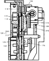
図2は実施例1の価値媒体処理装置の斜視図である。
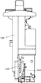
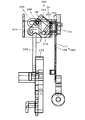
図3は実施例1の価値媒体処理装置の左側面図である。
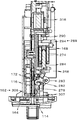
図4は実施例1の価値媒体処理装置の右側面図である。
図5は実施例1の価値媒体処理装置の平面図である。
図6は実施例1の価値媒体処理装置の底面図である。
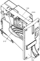
図7は実施例1の価値媒体処理装置の分解斜視図である。
図8は実施例1の価値媒体処理装置のドアプレートを取り外した斜視図である。
図9は実施例1の価値媒体処理装置のドアプレートの裏面斜視図である。
図10は実施例1の価値媒体処理装置のドアプレートを取りはずした左側面図である。
図11は図5におけるA―A線断面図である。
図12は図3におけるB―B線断面図である。
図13は図3におけるC―C線断面図である。
図14は図4におけるD―D線断面図である。
図15は図4におけるE―E線断面図である。
図16は図4におけるF―F線断面図である。
図17は図3におけるE―E線断面図である。
FIG. 1 is a front view of an IC coin suitable for the value medium processing apparatus of the first embodiment.
FIG. 2 is a perspective view of the value medium processing apparatus according to the first embodiment.
FIG. 3 is a left side view of the value medium processing apparatus according to the first embodiment.
FIG. 4 is a right side view of the value medium processing apparatus according to the first embodiment.
FIG. 5 is a plan view of the value medium processing apparatus according to the first embodiment.
FIG. 6 is a bottom view of the value medium processing apparatus according to the first embodiment.
FIG. 7 is an exploded perspective view of the value medium processing apparatus according to the first embodiment.
FIG. 8 is a perspective view of the value medium processing apparatus according to the first embodiment with the door plate removed.
FIG. 9 is a rear perspective view of the door plate of the value medium processing apparatus of the first embodiment.
FIG. 10 is a left side view of the value medium processing apparatus according to the first embodiment with the door plate removed.
11 is a cross-sectional view taken along line AA in FIG.
12 is a cross-sectional view taken along line BB in FIG.
13 is a cross-sectional view taken along line CC in FIG.
14 is a cross-sectional view taken along the line DD in FIG.
15 is a cross-sectional view taken along line EE in FIG.
16 is a cross-sectional view taken along line FF in FIG.
17 is a cross-sectional view taken along line EE in FIG.
まず実施例1の価値媒体処理装置に適したICコインが図1を参照して説明される。
ICコイン100は円盤状であって下向き傾斜通路を自重で転動でき、かつ、非接触で読込若しくは書込可能なアンテナ102を備えたICチップ104を内蔵し、コインCと同様の直径及び厚みに形成される。
詳述すれば、ICコイン100はリング形の磁性体よりなる外輪106、及びその内孔108に一体に構成したアンテナ102とICチップ104よりなるICタグモジュール110を埋め込んで構成されている。
ICタグモジュール110は、例えば樹脂により成形された二枚貝状のホルダ内に内蔵され、当該ホルダが内孔108に密に嵌め込まれ、接着剤等により外輪106と一体化される。
外輪106は、磁性体である鉄により構成することが出来るが、発錆及び模倣が容易であることから、例えば特許第3039838号のコイン用ステンレス鋼を用いることが好ましい。
ICコイン100は通常のコインC、例えば500円硬貨の直径よりも僅かに小径とし、及び僅かに厚く形成し、ICタグモジュール110が視認できないよう暗色樹脂性のホルダ内に内蔵したうえで内孔108に固定、または、側面に不透明なシールを貼付することが好ましい。
なお、ICコイン100は通常のコインよりも大径とし、通常のコインと区別しやすくしても良いが、装置が大型化するので通常のコインよりも僅かに小径及び僅かに厚く構成することがよい。
First, an IC coin suitable for the value medium processing apparatus of the first embodiment will be described with reference to FIG.
The
More specifically, the
The IC tag module 110 is built in, for example, a bivalve holder formed of resin, the holder is closely fitted in the
Although the
The
The
次に本発明の実施例1の価値媒体処理装置112が図2乃至17を参照して説明される。
価値媒体処理装置112は、投入口114、共通通路116、磁性レール118、ICコイン転動レール122、ICコイン通路124、コイン通路126、ICコインの保留装置128、通信装置132、ICコイン判別装置134、コイン特徴検出装置136、コイン判別装置140、ICコイン振分装置142、コイン振分装置144、コイン返却通路146、ICコイン返却通路148、返却口152、キャンセル手段154、進行阻止装置156、ICコインの媒体センサ158、投入阻止手段162、を含んでいる。
Next, the value
The value
まず、投入口114を説明する。
投入口114は、コインC及びICコイン100が投入される機能を有する。
投入口114は、コインC及びICコイン100の投入口を兼用している。
本実施例1では、投入口114にはICコイン100、10円、50円、100円及び500円コインの投入が予定されている。
よって、1円及び5円が投入された場合、偽貨として返却口152に戻される。
本実施例1において、投入口114は縦長矩形であって、その幅はICコイン100の厚みよりも僅かに大きく、かつその高さは500円コインの直径よりも僅かに大きく形成されている。
コインC及びICコイン100の投入口114を共通にすることにより、投入口設置範囲を小さくできるので、装置を小型化できる利点を有する。
本実施例1において、投入口114はフロントカバ164の上部中央に形成されている。
フロントカバ164は、金属製の板状のフロントパネル166の前面を覆うように固定されている。
First, the
The
The
In the first embodiment,
Therefore, when 1 yen and 5 yen are inserted, they are returned to the
In the first embodiment, the
Since the
In the first embodiment, the
The
次に共通通路116が図10、11及び14を参照して説明される。
共通通路116は、投入口114に投入されたICコイン100及びコインCが移動する垂立するスリット状の通路である。
共通通路116は、フロントパネル166に対し直角に固定され、かつ垂立するベースプレート168とベースプレート168に対しICコイン100の厚みよりも僅かに広い間隔で平行に配置されたドアプレート172との間に画定される。
The
The
The
ベースプレート168はほぼ矩形の板状体であり、耐摩耗性を有する樹脂などで一体成形される。
本実施例1では図7に示すように、投入口114に隣接するベースプレート168の側面にサブプレート174を固定することにより、薄いICコイン100を使用できるようにしている。
よって、本実施例1ではサブプレート174の側面とドアプレート172の側面との間に共通通路116が形成される。
しかし、サブプレート174はベースプレート168に固定され、実質的にベースプレート168と一体をなすので、説明においては便宜的にサブプレート174を含めてベースプレート168と称する。
投入口114の右側の垂立面に連続してベースプレート168の垂立するベース案内面176が配置され、投入口114に投入されたコインC及びICコイン100の右側面はこのベース案内面176に案内される。
なおベースプレート168は、後述のようにICコイン通路126及びコイン返却通路146をも画定する。
また、サブプレート174を取り外せばさらに厚いICコインも使用することができる。
The
In the first embodiment, as shown in FIG. 7, the
Therefore, in the first embodiment, the
However, since the
A
The
Further, if the
次にドアプレート172を図3及び図9を参照して説明する。
ドアプレート172は、共通通路116、ICコイン通路124及びコイン通路126の一側面を画定する機能を有する。
ドアプレート172は、非磁性体よりなるほぼ矩形の板状体であり、上端部がベースプレート168の軸受178、180に取り付けられた支軸182に揺動自在に支持され、付勢手段184としてのスプリング186によってベースプレート168に近づくよう回動力を受け、下端の突起188をベースプレート168に突き当てることによりベース案内面176及びドア案内面192間が所定の間隔で平行になるよう設定してある。
ドアプレート172は、樹脂により一体成形することが好ましい。
ドアプレート172のベースプレート168側のIドア案内面192の下端部からベース案内面176に向かってコイン転動レール194が突出している。
これによりドアプレート172は、共通通路116及びICコイン通路124においては、ICコイン100の厚みよりも僅かに広い間隔で、コイン通路126においては500円コインの厚みよりも僅かに大きい間隔でベースプレート168と平行に位置し、共通通路116、ICコイン通路124及びコイン通路126の一側面を画定する。
Next, the
The
The
The
A
As a result, the
次にICコイン通路124を図11を参照して説明する。
ICコイン通路124は、転動するICコイン100を案内する機能を有する。
ICコイン通路124は、上流ICコイン通路124Uと下流ICコイン通路124Dとにより構成される。
上流ICコイン通路124Uは、投入口114に続いて形成された通路であり、共通通路116の一部である。
上流ICコイン通路124Uと下流ICコイン通路124Dは全体として直線状に前下がりに構成されている。
前下がりとは、ICコインが自重によって転動できる傾斜を有していることをいう。
本説明において、特に断りがない場合、ICコイン通路124とは下流ICコイン通路124Dを指す。
Next, the
The
The
The upstream
The upstream
The forward drop means that the IC coin has an inclination that can roll by its own weight.
In this description, unless otherwise specified, the
ます上流ICコイン通路124Uを説明する。
共通通路116における投入口114の上縁に続いて所定の角度で前下がり(図10、11において左下がり)に直状の磁性レール118がベースプレート168のベース案内面176に固定されている。
上流ICコイン通路124Uは、上側を磁性レール118、左右側面をベースプレート168とドアプレート172に囲まれた倒立チャンネル形の底なし通路である。
磁性レール118は、本実施例においては鉄板により形成され、ベースプレート168の裏面側に配置した永久磁石196によって磁性を与えている。
永久磁石196を隔離することにより、磁性レール118の磁性を解除でき、鉄板等により製造された偽貨を容易に落下させることができるからである。
しかし、磁性レール118は永久磁石によって作ることもできる。
この構成により、投入口114に投入されたICコイン100は、磁性レール118にその周面が吸着され、磁性レール118からぶら下がった状態になる。
そして、磁性レール118の前下がりの傾斜によってICコイン100は自重によって磁性レール118にぶら下がった状態で転動して共通通路116を横断し、下流ICコイン通路124Dに達する。
投入コインの外周が磁性レール118によって吸着されない場合、例えば500円硬貨は、重力によって共通通路116を落下し、投入口114から勢いよく奥側に向けて投入されたコインCは後述の進行阻止装置156によりストップされて下流ICコイン通路124Dには到達できない。
よって、上流ICコイン通路124Uは共通通路116における磁性レール118に沿った通路である。
First, the upstream
A straight
The upstream
In this embodiment, the
This is because by isolating the
However, the
With this configuration, the peripheral surface of the
Then, the
When the outer periphery of the inserted coin is not attracted by the
Therefore, the upstream
次にICコイン100のための解除手段198を説明する。
解除手段198は、磁性レール118に吸着されているICコイン100を磁性レール118から引き離す機能を有する。
よって、解除手段198は同様の機能を有する異なる装置に変更することができる。
本実施例1において、磁性レール118の下面の延長上に非磁性体202、本実施例では樹脂製の解除レール204が配置されている。
解除レール204は非磁性体である樹脂であるため永久磁石196による磁束を発せず、磁性レール118にぶら下がって転動してきたICコイン100は、解除レール204に相対した場合、自重により落下する。
解除レール204を用いることにより、ICコイン100を磁性レール118に近接した位置において磁性レール118に吸着されないようにすることができるので、装置を小型化できる利点がある。
Next, the release means 198 for the
The release means 198 has a function of pulling the
Therefore, the release means 198 can be changed to a different device having the same function.
In the first embodiment, a
Since the
By using the
次に下流ICコイン通路124Dについて説明する。
下流ICコイン通路124Dは、磁性レール118から解除手段198によって落下させられたICコイン100が転動する通路である。
下流ICコイン通路124Dは、共通通路116(上流ICコイン通路124U)に続いて形成され、投入口114から離れるにしたがって下方に位置する下向きの傾斜通路であり、ICコイン転動レール122、ベースプレート168及びドアプレート172によって下及び左右を囲われた縦長スリット状の通路である。
換言すれば、下流ICコイン通路124Dは、ベースプレート168のベース案内面176、ドアプレート172のドア案内面192及びICコイン転動レール122によって画定された図11において左下がりに直線的に伸びる通路である。
ICコイン転動レール122は、直線状であって、磁性レール118の下方におけるICコイン通路124の下側に配置され、磁性レール118とほぼ平行に前下がりに傾斜している。
ICコイン転動レール122の投入口114側端部とフロントパネル166との間の落下開口206は、最大コインの直径よりも大きく設定され、コインCが共通通路116から後述するコイン通路126へ落下可能に形成されている。
また、ICコイン転動レール122の共通通路116側の端部は、図11に示すように垂直上方位置における磁性レール118の下流端部まで延び、解除手段198によって磁性レール118から落下させられたICコイン100が確実にICコイン転動レール122上に落下するようにしてある。
Next, the downstream
The downstream
The downstream
In other words, the downstream
The IC
The
Further, the end of the IC
次にコイン通路126が図11を参照して説明される。
コイン通路126は、投入口114に投入され、共通通路116から落下開口206を通って落下したコインCを案内する機能を有する。
コイン通路126は、共通通路116から垂直下方に連続し、ICコイン通路124の隣接下方においてICコイン通路124と平行に直線的に伸びている。
換言すれば、コイン通路126は投入口114側から垂直下方に延びた後、前下がりに傾斜している。
コイン通路126の幅はICコイン100の厚みよりも薄く、5円〜500円コインの中で最も厚い500円硬貨の厚みよりも僅かに広い幅を有している。
換言すれば、コインCはコイン通路126に落下できるが、ICコイン100が誤って落下してもコイン通路126へ落下できない。
しかし、コイン通路126の幅をICコイン100の厚みよりも僅かに大きくし、ICコイン100が落下可能にし、キャンセル操作を不要にすることもできる。
コイン通路126は、コインガイド208、コイン転動レール194、ベースプレート168及びドアプレート172によって囲われた断面矩形の縦長直線状傾斜通路である。
換言すれば、コイン通路126は、投入口114の側方位置から真下に延びた後、投入口114から遠ざかるにしたがって前下がりに傾斜している。
Next, the
The
The
In other words, the
The width of the
In other words, the coin C can fall into the
However, the width of the
The
In other words, the
コインCは投入口114から投入された直後、共通通路116をほぼ直径分移動した後、自重によって落下する。
よって、投入口114に連なる共通通路116は、コイン通路126の一部である。
ドアプレート172のドア案内面192の下端部からコイン転動レール194が突出し、コイン転動レール194上面はベースプレート168側に向かって下降するよう僅かに横向きに傾斜している。
この傾斜により、コインCはベースプレート168にもたれつつ転動するので転動位置が安定する効果がある。
ベースプレート168のベース案内面176とドアプレート172のドア案内面192との間隔は、選別するコインCの最大厚みよりも僅かに大きく設定されている。
しかし、この間隔をICコイン100の厚みよりも僅かに大きくし、ICコイン100が通過可能とすることもできる。
Immediately after being inserted from the
Therefore, the
A
Due to this inclination, the coin C rolls while leaning against the
The distance between the
However, this interval can be made slightly larger than the thickness of the
コイン転動レール194は、コインガイド208に連続して下流に配置され、ICコイン転動レール122と平行に形成されている。
コインガイド208は、上面が弧状に形成され、共通通路116から落下したコインCがコイン通路126へスムーズに案内されるように形成してある。
コインガイド208は、フロントパネル166に隣接したベースプレート168に固定された台形の金属板であり、コイン転動レール194に連なる落下転動面210が湾曲形成されている。
コインCの落下によって落下転動面210が摩耗しないため、及び、コインCの転動速度向上のためである。
以上より、コインCはドア案内面192及びベース案内面176によって側面を案内されつつ立った状態でコイン転動レール194上を転動可能である。
The
The
Since
As described above, the coin C can roll on the
次にキャンセル手段154が図4、15を参照して説明される。
キャンセル手段154は、ICコイン通路124若しくはコイン通路126においてジャムしたコインC、又は、投入したコインCをキャンセルし、返却口152に戻す機能を有する。
本実施例において、キャンセル手段154は、ドアプレート172、キャンセルレバ212、及び、第1リンク機構214を含んでいる。
Next, the canceling means 154 will be described with reference to FIGS.
The canceling
In the present embodiment, the cancel
まず、キャンセルレバ212を説明する。
キャンセルレバ212は、顧客がコインCをキャンセルするために操作するレバであり、ベースプレート168から横方向に突出する固定軸216にその中間を回転自在に取り付けられている。
キャンセルレバ212はフロントカバ164の投入口114に対し右側下方に形成された開口218からフロントカバ164の前方に突出され、顧客によって押し下げ可能に配置されている。
キャンセルレバ212はスプリング(図示せず)により図4において時計方向に回転力を受け、下部レバ222がフロントパネル166に対し平行に下方に伸び、図4に示すほぼ垂立する待機位置においてストッパ(図示せず)により停止され、保持される。
First, the cancel
The cancel
The cancel
The cancel
次に第1リンク機構214が図15を参照して説明される。
第1リンク機構214は、下部レバ222が図4において反時計方向に回動された場合、ドアプレート172の下端をベースプレート168から遠ざける方向に移動させる機能を有する。
第1リンク機構214は、ベースプレート168から横方向に延びるステー224から上方に突出する支軸226に回動自在に取り付けられたL形の第1揺動レバ228を含んでいる。
第1揺動レバ228の第1レバ228Aは下部レバ222によって押動され、図15において時計方向へ回動される。
第1揺動レバ228の第1レバ228Aは、ベースプレート168の開口を貫通してドアプレート172の下端部のコインガイド208の側面に当接し、押動可能である。
第1揺動レバ228はスプリング(図示せず)により図15において反時計方向に回転力を受けている。
これにより第2レバ228Bは、ベースプレート168の裏面に当接し、第1レバ228Aの先端がコインガイド208の側面から所定距離離れた位置に保持する。
Next, the
The
The
The
The
The
As a result, the
キャンセルレバ212が図4において反時計方向に回動された場合、下部レバ222は第1レバ228Aを押動するので、第1レバ228Aの先端はドアプレート172の下端部を押してベースプレート168から離隔させる。
これにより、ドアプレート172は支軸185を支点に回動し、ベースプレート168に対し傾斜され、コイン転動レール194の側端面とベース案内面176との隙間はコインCの厚み以上に離され、かつ、コイン転動レール194の上面は横方向に対して一層下向き傾斜になるので、その上に載っているコインCは、自重により落下する。
落下したコインCは、コイン通路126の下方においてベースプレート168に形成され、フロントパネル166側へ下向きに傾斜し、コイン返却通路146を構成するコイン返却ガイドレール232上に落下した後、自重によりその上を図11において右方向へ転動し、返却口152へ転げ落ちる。
返却口152は、コインCの両サイド及び前方を囲う溝状に形成されているので、コインCは返却口152において立った状態で保持される。
なお、コイン返却通路146は、図13に示すように湾曲形成し、中間において上下及び横方向に延びる邪魔板234を配置することにより、返却口152からコイン返却通路146の奥部が見えないように遮ることが好ましい。悪戯等防止のためである。
When the cancel
As a result, the
The dropped coin C is formed on the
Since the
The
次に媒体センサ158が図10を参照して説明される。
媒体センサ158は、共通通路116に配置され、投入口114に投入された価値媒体がコインCであるかICコイン100であるかを判別する機能を有する。
よって、媒体センサ158は同様の機能を有する他の装置に変更することができる。
本実施例1において、媒体センサ158は、ベースプレート168のベース案内面176に配置された投光部236、受光部238及びドアプレート172側に相対配置した光導体242を含んでいる。
投光部236及び受光部238は、共通通路116を横断する透過型の光電センサを構成するが、反射型光電センサや接触式センサ等に変更することができる。
投光部236及び受光部238は、後述の進行阻止装置156によって進行を停止されたICコイン100に面して配置される。
具体的には、投光部236からの投射光が共通通路116を横断し、光導体242によってUターンされて再び共通通路116を横断し、受光部238に受光される。
磁性レール118からICコイン100がぶら下がって投光部236又は受光部238と相対した場合、投光部236からの投射光は受光部238に受光されない。
よって、非受光状態が所定時間以上継続した場合、ICコイン100が共通通路116に存在しないと判断する。
具体的には、進行阻止装置156に停止され、磁性レール118に吸着されてぶら下がっているICコイン100によって投射光を連続して所定時間遮断され場合、検知信号を出力する。
Next, the
The
Therefore, the
In the first embodiment, the
The
The
Specifically, the projection light from the
When the
Therefore, when the non-light receiving state continues for a predetermined time or more, it is determined that the
Specifically, when the projection light is continuously blocked for a predetermined time by the
次にコイン特徴検出装置136が図3及び4を参照して説明される。
コイン特徴検出装置136は、コイン通路126を転動するコインCの正偽及び金種に関する特徴を検出する機能を有する。
コイン特徴検出装置136は、コイン通路126に沿ってベースプレート168及びドアプレート172に相対して固定されたコアにコイルを巻きつけた第1コイル体244、第2コイル体246、第3コイル体248を含んでいる。
第1コイル体244は、コインCの直径を検知するために用いられる。
第2コイル体246は、コインCの厚みを検知するために用いられる。
第3コイル体248は、コインCの材質を検知するために用いられる。
これら第1、第2及び第3のコイル体244、246、248からの出力は、コイン判別装置140に出力される。
Next coin characteristic detector 13 6 will be described with reference to FIGS. 3 and 4.
Coin characteristic detector 13 6 has a function of detecting the features of genuineness and denomination of the coin C rolling on the
Coin characteristic detector 13 6, the
The
The
The
The first, the output from the second and
次にコイン判別装置140を説明する。
コイン判別装置140は、コイン特徴検出装置136の出力を受信し、所定の基準値と比較してコインCの正貨及び偽貨並びに金種を判別し、関係装置に出力する。
コイン判別装置140が偽貨と判別した場合、コイン振分装置144にキャンセル信号CSを出力する。
Next, the
Coin discriminating
When the
次にコイン振分装置144が図4及び11を参照して説明される。
コイン振分装置144は、コイン通路126を転動するコインCをコイン返却通路146若しくは保留金庫(図示せず)へのコイン収納通路252に振り分ける機能を有する。
コイン振分装置144は、コイン振分体254と第1電磁アクチュエータ256と第2リンク機構258を有する。
コイン振分体254は、コイン通路126の延長上のキャンセル位置CP若しくはコイン収納通路252へ案内する収納位置SPに移動可能である。
コイン振分体254は、ベースプレート168の裏面から横方向へ突出する固定軸262に回転自在に取り付けられた第2揺動レバ266の先端から横方向に向かってベースプレート168に形成した弧状孔264を通ってコイン通路126に延びる棒体である。
第2揺動レバ266の他端267は、第1電磁アクチュエータ256の鉄心269に固定した蛙又270に挿入されている。
第2リンク機構258は、固定軸262、第2揺動レバ266、他端267、蛙又270によって構成される。
鉄心269は、スプリング(図示せず)により、図4において左方向へ付勢され、通常、コイン振分体254はキャンセル位置CPに保持される。
Next, the
The
The
The
The
The
The
Core 26 9, by a spring (not shown), is biased to the left in FIG. 4, typically, the
コイン特徴検出装置136の検知情報に基づいてコイン判別装置140が真正コインと判別した場合、第1電磁アクチュエータ256が励磁され、鉄心269が図4において右方へ移動されるので、第2揺動レバ266は反時計方向へ回動され、コイン振分体254は図11における収納位置SPに移動され、保持される。
コイン振分体254が収納位置SPに保持される場合、コイン通路126を転動するコインCは、コイン転動レール194からコイン振分体254上に落下し、横方向への慣性力も手伝って矢視AR方向に跳ね返り、コイン収納通路252に案内される。
コイン振分体254がキャンセル位置CPに位置する場合、コイン通路126から落下したコインCはコイン振分体254に衝突して矢視AC方向に跳ね返り、図11において右方へ案内されるので、コイン返却通路146のコイン返却ガイドレール232上を転動して返却口152へ戻される。
If the coin characteristic detector 13 6 of the detection information coin discriminating device on the basis of 140 is determined to true coin, the first
When the
When the
次に進行阻止装置156が図4、5、10、11、14を参照して説明される。
進行阻止装置156は、ICコイン100が共通通路116から下流ICコイン通路124Dに進行するのを阻止する機能、投入口114から勢いよく投入されたコインCが誤って下流ICコイン通路124Dに進行するのを防止しコイン通路126に案内する機能を有する。
進行阻止装置156は、逸らせ体268、第3リンク機構272、及び第2電磁アクチュエータ274を含んでいる。
逸らせ体268は、板状であり、図10に示すようにL形に形成され、ベースプレート168の裏面側においてベースプレート168に対し平行に固定された固定軸282に回動自在に取り付けた第3揺動レバ278の一端に対し直角に折り曲げられて形成されている。
逸らせ体268は垂立部268A及び下向き傾斜部268Bを有し、投入されたコインCは垂立部268Aに衝突して転がり慣性力を消去され、自重で下方へ落下してコインガイド208の落下転動面210上に落下する。
第3揺動レバ278の固定軸282よりもベースプレート168に遠い位置から上方に突出する軸283に第3リンク機構272の端部が回動自在に取り付けられている。
第3リンク機構272の他端は、第2電磁アクチュエータ274の鉄心284に回動自在に取り付けられている。
鉄心284は、スプリング(図示せず)によって突出方向(図5において下方向)に付勢されている。
Next, the
The
The
The deflecting
The deflecting
The end of the
The other end of the
The
よって、第2電磁アクチュエータ274が励磁され、鉄心284が吸引され、図14において上方へ移動された場合、第3揺動レバ278は反時計方向へ回動され、逸らせ体268は共通通路116に進行し、共通通路116をほぼ横断するよう位置する。
第2電磁アクチュエータ274が消磁された場合、鉄心284は図示しないスプリングにより図14における下方へ移動される。
第3揺動レバ278は反時計方向へ回動され、逸らせ体268が共通通路116から退出する(図14の位置)。
このとき、後述のように、阻止片306が投入口114に隣接した共通通路116に進出するので、コインCを投入口114に投入することはできない。
したがって、逸らせ体268よりも投入口114側が共通通路116であり、逸らせ体268よりも下流が下流ICコイン通路124Dであり、下流ICコイン通路124Dの入口285は逸らせ体268に隣接する下流位置である。
Therefore, when the second
When the second
The
At this time, as will be described later, since the blocking
Therefore, the
次にICコイン保留装置128が図11、14を参照して説明される。
ICコイン保留装置128は、ICコイン100を下流ICコイン通路124Dの所定位置に保留する機能を有する。
ICコイン保留装置128は、停止片286、第2電磁アクチュエータ274、及び第4リンク機構288を含んでいる。
Next, the IC
The IC
The IC
停止片286は、下流ICコイン通路124Dの上方において、ベースプレート168から側方に突出する固定軸292に回動自在に取り付けられ、ベースプレート168に隣接し、ベースプレート168に対し平行な平面内において回動できる。
第4リンク機構288は、第2電磁アクチュエータ274の鉄心284に固定され、ベースプレート168に形成された横向きのガイド孔290にガイドされつつ横方向に往復動可能に設けたスライド片294、スライド片294から横方向へ突出し、ベースプレート168を貫通するピン296及び、停止片286に形成した長孔298を含み、ピン296が長孔298にスライド可能に挿入されている。
The
The
第2電磁アクチュエータ274が消磁されている場合、スライド片294は図4において最左方に位置しているので、停止片286は図11において時計方向に回動された保持位置SPに保持される。
停止片286が保持位置SPに位置する場合、ICコイン転動レール122上を転動してきたICコイン100は、停止片286の先端に当接して転動を阻止され、保留位置HPに保持される。
When the second
When the
第2電磁アクチュエータ274が励磁された場合、鉄心284が図4において右方へ移動されるため、停止片286は図11において反時計方向へ回動される。
これにより、停止片286の先端はICコイン100に当接しない位置に移動され(鎖線示位置)、ICコイン100はICコイン通路124を図11においてさらに左方へ転動可能になる。
下流ICコイン通路124Dを転動するICコイン100は、ICコイン振分装置142によってICコイン収納通路302又はICコイン返却通路148へ案内される。
When the second
As a result, the tip of the
The
次に投入阻止手段162を図11、14を参照して説明する。
投入阻止手段162は、ICコイン100が保留位置HPに保留されている場合、コインC及びICコイン100を投入口114に投入できないようにする機能を有する。
投入I阻止手段162は、第3揺動レバ278の他端部に形成されたL形の先端である阻止片306である。
阻止片306は、投入口114の後方のフロントパネル166に近接した位置において、ベースプレート168の開口307を通って共通通路116に進退可能である。
よって、逸らせ体268と阻止片306とは第3揺動レバ278の揺動によって反対位相で共通通路116に進退する。
詳述すれば、逸らせ体268が共通通路116に位置している場合、阻止片306は共通通路116から退出する。
逸らせ体268が共通通路116から退出している場合、阻止片306は投入口114に相対する共通通路116に位置する。
よって、阻止片306が共通通路116に位置する場合、コインC及びICコイン100を投入口114に投入することが出来ない。
Next, the
The
The throwing-in blocking means 162 is a
The blocking
Therefore, the deflecting
More specifically, when the deflecting
When the deflecting
Therefore, when the
次に通信装置132を説明する。
通信装置132は、保留位置HPに保留されたICコイン100のICチップ104と価値情報を通信によって読込及び/又は書込する機能を有する。
本実施例において通信装置132は、ベースプレート168に固定され、通信機能を有するIC及びアンテナを搭載した通信基板308である。
通信装置132は、ICコイン保留装置128によって保留されたICコイン100の側方のベースプレート168の裏面側に配置されている。
Next, the
The
In this embodiment, the
The
次にICコイン振分装置142が図4、11、12、14を参照して説明される。
ICコイン振分装置142は、停止片286による保持を解除されたICコイン100をICコインICコイン収納通路302若しくはICコイン返却通路148に振分る機能を有する。
ICコイン振分装置142は、ICコイン振分体314及び第3電磁アクチュエータ316を含んでいる。
ICコイン振分体314は縦軸318の上下端部がベースプレート168に形成された軸受322、324に回転自在に支持されている。
縦軸318の上端部に側方に突出する被動レバ326が固定され、被動レバ326の自由端は第3電磁アクチュエータ316の鉄心328の先端に固定された駆動体332の溝334に挿入されている。
Next, the IC
The IC
The IC
The IC
第3電磁アクチュエータ316が消磁されている場合、鉄心328はスプリング(図示せず)によって突出され図12に示す待機位置に保持される。
待機位置において、ICコイン振分体314の一側面である返却案内面338はICコイン通路124を形成するベース案内面176に連なって後、下方に向かうにしたがって横方向へ突出するよう緩やかに湾曲している。
この湾曲によって、ICコイン100は、ICコイン返却通路148に案内される。
図13に示すように、ICコイン返却通路148は、コイン転動レール194上に形成され、隔壁336によって区切られてコイン返却通路146に並列配置されている。
隔壁336はドアプレート172の延長上に位置している。
When the third conductive
At the standby position, the
The
As shown in FIG. 13, the IC
The
第3電磁アクチュエータ316が励磁された場合、ICコイン振分体314は図12において時計方向に回動され、返却案内面338の裏面側の収納案内面342がドアプレート172のドア案内面192の延長上に位置する。
収納案内面342は、ICコイン100をICコイン収納通路302に案内するよう湾曲形成されている。
これにより、ICコイン保留装置128の保持を解除されたICコイン100は、収納案内面342によってICコイン収納通路302へ案内される。
図6に示すように、ICコイン収納通路302はベースプレート168によってコイン収納通路252に対し区画され、並列配置されている。
When the third conductive
The
As a result, the
As shown in FIG. 6, the IC
次にICコイン100のための落下防止装置344を図8、10を参照して説明する。
落下防止装置344は、ICコイン保留装置128によってICコイン100が保留されている場合、ドアプレート172がキャンセルレバ212の操作によって移動された場合であってもICコイン100が落下しないよう保持する機能を有する。
落下防止装置344は、ICコイン保留装置128の上流側においてベースプレート168のベース案内面176に対しICコイン100の厚みよりも僅かに間隔をあけて平行に配置した棒状のサポータ346である。
サポータ346はベースプレート168に固定されている。
この構成により、ICコイン100が停止片286に停止されている場合、一面はベース案内面176、他面はサポータ346に案内され、ICコイン転動レール122上に垂立状態に保持される。
よって、ドアプレート172がキャンセルレバ212の操作によって移動されてもICコイン100がICコイン転動レール122上から落下しない。
Next, a
The
Fall prevention equipment 3 44 is a rod-shaped
The
With this configuration, when the
Therefore, even if the
なお、コイン収納通路252に糸吊り防止手段344を配置することが好ましい。
本実施例の糸吊り防止手段344は、軸346に対し揺動可能に取り付けた扇形の阻止体348である。
通常、重力により阻止体348の一部がコイン収納通路252に突出した状態に垂下される(図11鎖線示)。
正貨コインCが通過する場合、阻止体348は当該コインCにより移動され(図11実線示)、当該コインCは通過することが出来る。
コインCが通過した後、阻止体348は自己モーメントにより元に戻る。
これにより、糸吊りしたコインCを引き上げた場合、当該コインCによって阻止体348はコイン収納通路252内に引き入れられるように力を受けるので、阻止体348に移動を阻止され、引き上げることはできない。
It is preferable to dispose the thread suspension preventing means 344 in the
The yarn suspension preventing means 344 of the present embodiment is a fan-shaped
Normally, a part of the blocking
When the genuine coin C passes, the blocking
After the coin C has passed, the blocking
Thereby, when the coin C suspended from the thread is pulled up, the
フロントカバ164にICコイン100若しくはICカードCDのICチップ104に記憶された価値情報を表示するための表示器352を装着することが好ましい。
表示器352は、上向きに形成し、顧客から見えやすいように配置することが好ましい。
また、フロントカバ164を透光性樹脂にて製造し、フロントカバ164裏面側のフロントパネル166に多数のLEDを配置して発光させることにより、装飾性を高めることができる。
さらに、スピーカーを組み込むことにより、音楽やアナウンスを流すことができる。
It is preferable to attach a
The
Further, the
In addition, music and announcements can be played by incorporating speakers.
次に本実施例1の作用を説明する。
まず正貨コインCを投入したケースを説明する。
本価値媒体処理装置112がスタンバイ状態にない場合、進行阻止装置156の第2電磁アクチュエータ274は、消磁され、鉄心284がスプリング(図示せず)によって下方に移動され、第3リンク機構272を介して第3揺動レバ278は時計方向へ回動され、最時計回り位置に位置する(図14の状態)。
これにより、逸らせ体268は共通通路116から退出した位置に保持される。
一方、逆位相に移動される阻止片306は、共通通路116に進出している。
よって、投入口114には、コインC及びICコイン100を投入することができない。
Next, the operation of the first embodiment will be described.
First, a case where the coin C is inserted will be described.
When the value
As a result, the deflecting
On the other hand, the blocking
Therefore, the coin C and the
価値媒体処理装置112がスタンバイ状態にされた場合、第2電磁アクチュエータ274は励磁され、鉄心284が図14において引き上げられ、第3リンク機構272を介して第3揺動レバ278は反時計方向へ回動される。
これにより、逸らせ体268は共通通路116に進出し、阻止片306は共通通路116から退出する。
よって、投入口114にコインC又はICコイン100が投入可能になる。
When the value
As a result, the deflecting
Therefore, the coin C or the
通常、コイン振分装置144の第1電磁アクチュエータ256は消磁され、鉄心269はスプリング(図示せず)によって図4において右方へ移動されるので、第2リンク機構258を介して第2揺動レバ266が最時計方向に回動される(図4の状態)。
これにより、コイン振分体254はキャンセル位置CP(図11における実線位置)に保持される。
通常、ICコイン振分装置142の第3電磁アクチュエータ316も消磁され、ICコイン振分体314はICコイン100のキャンセル位置に保持される。
換言すれば、ICコイン振分体314の返却案内面338がベースプレート168のベース案内面176に連続的に連なっている位置に保持される(図12の状態)。
Typically, the first
As a result, the
Normally, the third
In other words, the
投入口114に投入されたコインCは、重力により落下し、また、勢いよく投入された場合には逸らせ体268の垂立部268Aに衝突する。
垂立部268Aに衝突したコインCは投入口114側へ跳ね返って横方向への移動慣性力を消滅させられ、重力によりコインガイド208上に落下する。
The coin C inserted into the
Coin C collides with the
このときコインCは媒体センサ158の投光部236から受光部238への光軸を遮断するが短時間であるため、ICコイン100としては検知されず第2電磁アクチュエータ274は励磁されたままである。
コインガイド208の落下転動面210に落下したコインCは、その円弧面により加速されつつ転動し、次いでコイン転動レール194上を転動する。
コインCはコイン転動レール194上を転動する過程で第1、第2及び第3のコイル体244、246、248に順次相対し、コインCの直径、材質及び厚みに関する特徴情報を検知される。
コイン判別装置140は、これらの特徴情報に基づいてコインCの真偽及び金種を判別する。
At this time, the coin C blocks the optical axis from the
The coin C dropped on the falling rolling
In the process of rolling on the
The
本ケースは正貨として判別され、第1電磁アクチュエータ256が所定時間励磁される。
この励磁によって、鉄心269は図4において右方へ引かれるので、第2揺動レバ266は反時計方向へ回動される。
これにより、コイン振分体254は図11に示す保留位置SPへ移動される。
コイン転動レール194から落下したコインCはコイン振分体254上に落下して図11における矢視ARの左方へ跳ね返り、コイン収納通路252へ案内される。
コイン収納通路252を落下するコインCは、阻止体348を図11において時計方向へ回動させて通過し、保留金庫(図示せず)に保留される。
保留されたコインCを糸吊りにより引き上げようとしても前述のように阻止体348に阻止されて引き上げることができない。
This case is determined as a true coin, and the first
This excitation, since the iron core 26 9 is pulled to the right in FIG. 4, the
Thereby, the
The coin C dropped from the
The coin C falling in the
Even if an attempt is made to pull up the held coin C by the thread suspension, it is blocked by the blocking
次に偽コインが投入されたケースを説明する。
投入口114に投入された偽コインは、前述同様にコイン通路126のコイン転動レール194上を転動する。
コイン特徴検出装置136は第1、第2及び第3のコイル体244、246、248からの特徴情報を出力し、コイン判別装置140は偽信号を出力するので、第1電磁アクチュエータ256は励磁されない。
これにより、コイン振分体254は図11におけるキャンセル位置CPを継続するので、偽コインはコイン振分体254に衝突してコイン返却通路146へ案内され、返却口152に保持されてキャンセルされる。
Next, a case where a fake coin is inserted will be described.
The false coins inserted into the
Coin characteristic detector 13 6 first outputs the feature information from the second and
As a result, the
次にICコイン100を投入口114に投入したケースを説明する。
ICコイン100は、磁性レール118に吸着され、磁性レール118からぶら下がった状態で共通通路116を逸らせ体268に向かって転動する。
ICコイン100は、ほぼ直径分移動した位置で逸らせ体268に進行を阻止され、磁性レールからぶら下がった状態で静止する。
これにより、投光部236からの投射光はICコイン100によって所定時間以上遮断されるので、媒体センサ158はICコイン100の検知信号を出力する。
Next, a case where the
The
The
As a result, the projection light from the
この検知信号によって、第2電磁アクチュエータ274が消磁され、鉄心284が図14において下方へ移動されるので、第3揺動レバ278は時計方向へ回動され、逸らせ体268は共通通路116から退出すると共に阻止片306は共通通路116に進出し、コインC及びICコイン100は投入不可能になる(図14に示す状態)。
逸らせ体268の共通通路116からの退出によって、ICコイン100は重力によって磁性レール118からぶら下がった状態で入口285を通って下流ICコイン通路124Dに転動して進行する。
ICコイン100が逸らせ体268との相対位置を通過した後、すなわち、投光部236からの投射光を受光部238が受光したことを検知した後、所定時間経過後、第2電磁アクチュエータ274は再び励磁される。
これによって、逸らせ体268は再び共通通路116に進行し、阻止片306は共通通路116から退出する。
また、スライド片294、ピン296を介して停止片286が図11の実線位置に回動され、ICコイン100の保持位置SPに保持される。
Due to this detection signal, the second
As the deflecting
After the
As a result, the deflecting
Moreover, the slide piece 294, locking
逸らせ体268の共通通路116からの退出により、ICコイン100は磁性レール118にぶら下がった状態で転動した後、解除レール204に相対する。
これにより、ICコイン100は磁性レール118によって吸着されないので重力によりICコイン転動レール122上に落下し、次いでICコイン転動レール122上を下方に向かって転動して上端部が停止片286によって停止され、保留位置HPにおいて保留される(図14)。
ICコイン100は保留位置HPに保留された後、通信装置132によってICコイン100に内蔵されたICチップ104と通信し、価値情報を読込若しくは書き込む。
ICコイン100がICコイン100保留位置HPに保留された場合、ICコイン100はベースプレート168とサポータ346との間に保持されるので、ICコイン転動レール122上から落下することがないので読込及び/又は書込エラを生じることはない。
The
Thereby, since the
After the
When the
ICコイン100の価値情報がゼロになった場合、ICコイン振分装置142の第3電磁アクチュエータ316が励磁され、図4において駆動体332が左方に移動されるので、被動レバ326の先端が左方へ移動され、縦軸318は図16において時計方向へ回動される。
この回動によって、ICコイン振分体314が時計方向に回動され、収納案内面342がドアプレート172のドア案内面192と面一になる収納位置に保持される。
When the value information of the
By this rotation, the IC
次いで第2電磁アクチュエータ274が励磁され、停止片286が図14において上方へ移動される。
これにより、スライド片294が同方向へ移動され、ピン296を介して停止片282が図11において反時計方向に回動され、非保持位置に移動される(図11の鎖線示位置)。
停止片282の係止を解除されたICコイン100は、自重及びICコイン転動レール122の傾斜によって転動を開始し、ICコイン振分体314に達する。
Next, the second
As a result, the slide piece 294 is moved in the same direction, and the
The
ICコイン振分体314が保留位置にあるため、ICコイン100は収納案内面342に案内されてICコイン収納通路302へ案内される。
ICコイン100に価値情報が残存している場合、第3電磁アクチュエータ316は励磁されず、キャンセル位置に保持される。
換言すれば、ICコイン振分体314の返却案内面338がベースプレート168のベース案内面176と面一の位置に保持される。
この場合、ICコイン100は、ICコイン振分体314によってICコイン返却通路148に案内され、返却口152へ戻される。
Since the IC
When the value information remains in the
In other words, the
In this case, the
なお、図11に示すように、返却口152の先端部の弧状内面に磁石353を取り付けることが好ましい。
転動してきたICコイン100の外輪106が磁石353に吸着され、ICコイン100が反動により跳ね戻りしないからである。
磁石353は返却口152の外面に取り付けてもよい。
Incidentally, as shown in FIG. 11, it is preferable to attach the magnet 35 3 arcuately inner surface of the front end portion of the
The
Magnet 35 3 may be attached to the outer surface of the
図18は実施例2の価値媒体処理装置の右側面図である。
図19は実施例2の価値媒体処理装置の磁化・非磁化手段の分解斜視図である。
図20は図18におけるH―H線断面図である。
図21は、実施例2の価値媒体処理装置における磁化・非磁化手段の機構説明図である。
図22は、実施例2の価値媒体処理装置における磁化・非磁化手段の作用説明図である。
FIG. 18 is a right side view of the value medium processing apparatus according to the second embodiment.
FIG. 19 is an exploded perspective view of the magnetization / non-magnetization means of the value medium processing apparatus according to the second embodiment.
20 is a cross-sectional view taken along line HH in FIG.
FIG. 21 is an explanatory diagram of the mechanism of the magnetization / non-magnetization means in the value medium processing apparatus of the second embodiment.
FIG. 22 is an explanatory diagram of the operation of the magnetization / non-magnetization means in the value medium processing apparatus of the second embodiment.
実施例2は、磁性レール118の磁化・非磁化手段360を実施例1の価値媒体処理装置112に装着した例である。
磁化・非磁化手段360は、必要に応じ磁性レール118を磁化し、又は非磁化する機能を有し、本実施例2においては、前記磁性レール118に磁性を帯びさせる作用状態と帯びさせない不作用状態とに選択的に切り替えられる磁石362を含んでいる。
本実施例2において、磁石362は永久磁石364であり、第5リンク機構366によりキャンセルレバ212に連結されている。
The second embodiment is an example in which the magnetizing / non-magnetizing means 360 of the
The magnetizing / non-magnetizing means 360 has a function of magnetizing or demagnetizing the
In the second embodiment, the
まず永久磁石364を説明する。
永久磁石364は、希土類磁石等の強磁石を用いることが好ましい。ICコイン100を確実に吸着するためである。
本実施例2において、永久磁石364は矩形立方体であり、非磁性体である樹脂製のホルダ368の横向き有底装着孔370に内装されている。
ホルダ368は、ベースプレート168の磁性レール118が装着された側の裏面側に、磁性レール118と平行に配置された支軸372に回動自在に取り付けられている。
換言すれば、永久磁石364は支軸372と同様に前下がりに傾斜し、かつ、磁性レール118と平行に並設されている。
支軸372は、ベースプレート168に固定されたチャンネル型のブラケット374に取り付けられている。
ホルダ368は、支軸372に対し回動し、作用位置OPと非作用位置NPに位置することができる(図21、22参照)。
First, the
The
In the second embodiment, the
The
In other words, the
The
The
作用位置OPにおいて、ホルダ368の先端部はベースプレート168の矩形の透孔376に相対し、底壁380の外表面である作用面382はサブプレート174の磁性レール118に相対する背面に密接する。
詳述すれば、支軸372はホルダ368の軸孔383に自由度をもって貫通し、ホルダ368は支軸372のスラスト方向だけでなく、ラジアル方向にも僅かに移動することができる。
磁性レール118と永久磁石364との間には、非磁性体よりなる隔壁384を配置することが好ましい。
磁性レール118と永久磁石364との間の距離を一定にし、永久磁石364による磁性レール118の磁化を大凡一定にするためである。
At the operating position OP, the tip of the
If specifically, the
A
This is because the distance between the
本実施例2において隔壁384は、サブプレート177、ベースプレート168とホルダ368の底壁380により構成され、その厚みは0.5ミリ以上1.5ミリ以下であることが好ましい。
隔壁384が薄すぎ場合底壁380の強度を維持することができず、厚すぎる場合さらに高価な強力永久磁石を使用せねばならないからである。
In the second embodiment, the
This is because if the
隔壁384は、非磁性体である樹脂により構成することが安価かつ形状の自由度が高いので好ましい。
非作用位置NPにおいて、永久磁石364は、磁性レール118に実質的に磁性を与えない位置まで磁性レール118から離れる。
実質的とは、磁性レール118に磁力吸着されているICコイン100が自重により自然落下できる磁力をいう。
図22に示すように永久磁石364による磁化の範囲は、永久磁石364の面に対し直角方向に大きく作用する。
換言すれば、磁性レール118に対し直線的に離れる方向に移動するよりも、磁石面が磁性レール118に傾斜する方向に移動させた方が小移動量であっても磁力の作用範囲が減少する。
本実施例2においては、ホルダ368が支軸372回りを回動することにより、作用面382が磁性レール118に対し傾斜しつつ当該磁性レール118から離れるように構成されている。
これにより、価値媒体処理装置100全体を小型できる利点がある。
The
In the non-operation position NP, the
The term “substantially” refers to a magnetic force that allows the
As shown in FIG. 22, the range of magnetization by the
In other words, the range of action of the magnetic force is reduced even if the amount of movement is smaller when the magnet surface is moved in a direction inclined to the
In the second embodiment, the
Thereby, there is an advantage that the entire value
次に第5リンク機構366を説明する。
第5リンク機構366は、キャンセルレバ212とホルダ368を連動させる機能を有する。
第5リンク機構366は、ホルダ368に、支軸372に対しオフセットし、かつ平行に取り付けられたピン386、コンロッド388及び軸ピン392を含んでいる。
コンロッド388の下端部は、軸ピン392が軸孔394を貫通ししてキャンセルレバ212のオフセット位置に軸支されている。
Next, the
The
The
The lower end of Konro'
コンロッド388の上端部において横方向に伸びる長孔396にピン386が摺動自在に貫通している。
これにより、キャンセルレバ212が図18において反時計方向に回動された場合、軸ピン392、コンロッド388及びピン386は図21において下方へ引かれるので、ホルダ368は図21・22において反時計方向に回動され、作用面382は上向きを呈して磁性レール118に対し傾斜すると共に、離れる。
このときピン386は長孔396をスライドし、第5リンク機構366の下方動を許容する。
この位置が非作用位置NPである。
非作用位置NPにおいて、永久磁石364の磁力MFの作用範囲が磁性レール118から離れて外れ、磁性レール118の磁力は急激に減少するので磁性レール118に吸着されたICコイン100は自重で落下可能となる。
特に、回動により永久磁石364を磁性レール118から離すため、永久磁石364の移動量が小さくとも磁性レール118の磁性を実質的に非磁化できる。
A
Accordingly, when the cancel
This
This position is the non-action position NP.
In the non-acting position NP,
In particular, since the
キャンセルレバ212の押し下げを解除した場合、図示しないスプリングの付勢力によりキャンセルレバ212が図18において時計方向に回動され、図18に示す待機位置に復帰する。
これにより、軸ピン392、コンロッド388及びピン386を介してホルダ368が図21・22において時計方向に回動され、作用面382は永久磁石364による磁力により、ベースプレート168の背面に吸着し、実線位置の作用位置OPに保持される。
これにより、磁性レール118は永久磁石364の磁力MFの作用により磁化される。
When release of the cancel
As a result, the
As a result, the
次に第2実施例の作用を説明する。
通常状態において、ホルダ368の作用面382は磁性レール118の側方に位置し、永久磁石364の磁力によって磁性レール118は磁化されている。
よって、ICコイン100を投入口114に投入した場合、実施例1と同様に処理される。
Next, the operation of the second embodiment will be described.
In a normal state, the working
Therefore, when the
ICコイン100を投入口114に投入した直後にキャンセルする場合、キャンセルレバ212が図18において反時計方向に回動される。
これにより、軸ピン392、コンロッド388及びピン386を介してホルダ368が支軸372を中心に図21・22において反時計方向に回動される。
ホルダ368の回動の際、ピン386は長孔396を相対移動できるので、ホルダ368の支軸372回りの回動が阻止されることはない。
ホルダ368の回動によって、作用面382は磁性レール118の側方から離れると共に上向きに変位するので、磁性レール118に対する磁力MFの作用が急速に弱まり、磁性レール118に吸着されているICコイン100は自重により落下する。
落下したICコイン100はICコイン返却通路148に達し、ICコイン返却通路148を転動して返却口152に戻される。
When canceling immediately after the
As a result, the
When the
By the rotation of the
The dropped
図23は、実施例3の価値媒体処理装置における磁化・非磁化手段の概略説明図である。
次に実施例3を図23を参照して説明する。
ベースプレート168の磁性レール118に対し背面側に鉄心398にコイル400を巻き付けた電磁石402を配置してある。
この電磁石402が磁石362であり、磁化・非磁化手段360である。
コイル400は直流電源404、キャンセルスイッチング回路406及びスタンバイスイッチング回路408と直列に配置されている。
キャンセルスイッチング回路406は、キャンセルレバ212が待機位置にある場合閉止され、所定量回動した場合開放にされる常閉のスイッチング回路である。
スタンバイスイッチング回路408は、価値媒体処理装置112がスタンバイ状態にされた場合閉止され、スタンバイ状態でない場合開放される常開のスイッチング回路である。
FIG. 23 is a schematic explanatory diagram of magnetization / non-magnetization means in the value medium processing apparatus of the third embodiment.
Next, Embodiment 3 will be described with reference to FIG.
An
The
Coil 400 is arranged in series with
The cancel switching
The
次に実施例3の作用を説明する。
価値媒体処理装置112がスタンバイ状態にされた場合、換言すれば第2電磁アクチュエータ274が励磁された場合、スタンバイスイッチング回路408は閉止される。
これにより、キャンセルスイッチング回路406は閉止されているのでコイル398に電流が流れ、鉄心398に磁力が発生し、電磁石402が磁力を発生する。
磁性レール118は鉄心398の磁力によって磁化され、ICコイン100が投入された場合、ICコイン100の外輪106を磁力吸着できる。
Next, the operation of the third embodiment will be described.
When the value
Accordingly, since the cancel switching
The
ICコイン100を投入口114に投入した場合、磁性レール118が磁化されているので、実施例1と同様にICコイン100は処理される。
ICコイン100を投入口114に投入した直後にキャンセルする場合、キャンセルレバ212が図18において反時計方向に回動される。
所定量回動された場合、キャンセルスイッチング回路406が開放されるので電磁石402は消磁し、磁性レール118は磁性を失い、ICコイン100は自重によりICコイン返却通路148に落下し、ICコイン返却通路148を転動して返却口152に戻される。
When the
When canceling immediately after the
When it is rotated by a predetermined amount, the cancel switching
C コイン
100 ICコイン
106 磁性リング(外輪)
110 ICタグモジュール
114 投入口
112 価値媒体処理装置
118 磁性レール
122 ICコイン転動レール
116 共通通路
124 ICコイン通路
126 コイン通路
128 ICコインの保留装置
132 通信装置
134 ICコイン判別装置
136 コイン特徴検出装置
140 コイン判別装置
142 ICコイン振分装置
144 コイン振分装置
146 コイン返却通路
148 ICコイン返却通路
152 返却口
156 進行阻止装置
158 媒体センサ
162 阻止手段
274 アクチュエータ
285 ICコイン通路入口
360 磁化・非磁化手段
362 磁石
364 永久磁石
402 電磁石
C coin
100 IC coin
106 Magnetic ring (outer ring)
110 IC tag module
114 slot
112 Value medium processing equipment
118 Magnetic rail
122 IC coin rolling rail
116 Common passage
124 IC coin passage
126 Coin passage
128 IC coin holding device
132 Communication equipment
134 IC coin discriminator
136 Coin feature detection device
140 coin discriminator
142 IC coin sorting device
144 Coin sorting device
146 Coin return passage
148 IC coin return passage
152 Return port
156 Progression prevention device
158 Media sensor
162 Blocking means
274 Actuator
285 IC coin passage entrance
360 Magnetized / non-magnetized means
362 magnet
364 Permanent magnet
402 electromagnet
Claims (1)
前記投入口(114)の上縁から前下がりに傾斜する磁性レール(118)を設け、前記磁性レール(118)の下方における少なくとも最大径コインの直径よりも前記投入口(114)から離れた位置に前下がりのICコイン転動レール(122)を配置すると共に前記投入口(114)から前記ICコイン転動レール(118)までを前記コイン(C)が重力により落下できるコイン通路(126)にしたことを特徴とする価値媒体処理装置。 The authenticity of the coin (C) inserted into the common slot (114) of the coin (C) and the IC coin (100) is discriminated and sorted into an accepted coin and a return coin, and the IC coin ( 100) in the value medium processing device that sorts into accepted IC coins or returned IC coins
A magnetic rail (118) that slopes forward and downward from the upper edge of the insertion slot (114) is provided, and a position that is farther from the insertion slot (114) than the diameter of at least the largest coin below the magnetic rail (118). An IC coin rolling rail (122) that is lowered forward is disposed on the coin path (126) through which the coin (C) can fall by gravity from the insertion slot (114) to the IC coin rolling rail (118). A value medium processing apparatus characterized by that.
Priority Applications (1)
| Application Number | Priority Date | Filing Date | Title |
|---|---|---|---|
| JP2008065825A JP5163979B2 (en) | 2008-02-14 | 2008-03-14 | Value medium processing apparatus and IC coin used therefor |
Applications Claiming Priority (3)
| Application Number | Priority Date | Filing Date | Title |
|---|---|---|---|
| JP2008033735 | 2008-02-14 | ||
| JP2008033735 | 2008-02-14 | ||
| JP2008065825A JP5163979B2 (en) | 2008-02-14 | 2008-03-14 | Value medium processing apparatus and IC coin used therefor |
Publications (3)
| Publication Number | Publication Date |
|---|---|
| JP2009217784A JP2009217784A (en) | 2009-09-24 |
| JP2009217784A5 JP2009217784A5 (en) | 2011-04-14 |
| JP5163979B2 true JP5163979B2 (en) | 2013-03-13 |
Family
ID=41189521
Family Applications (1)
| Application Number | Title | Priority Date | Filing Date |
|---|---|---|---|
| JP2008065825A Active JP5163979B2 (en) | 2008-02-14 | 2008-03-14 | Value medium processing apparatus and IC coin used therefor |
Country Status (1)
| Country | Link |
|---|---|
| JP (1) | JP5163979B2 (en) |
Family Cites Families (4)
| Publication number | Priority date | Publication date | Assignee | Title |
|---|---|---|---|---|
| JP2002063623A (en) * | 2000-08-21 | 2002-02-28 | Tamura Electric Works Ltd | Coin processor |
| JP2005293097A (en) * | 2004-03-31 | 2005-10-20 | Terajima Yoshikazu | Coin discrimination device and inter-game boards ball dispenser equipped with the same |
| JP2006189986A (en) * | 2004-12-29 | 2006-07-20 | Mk Systems Kk | Sorting mechanism for coin like ic tag and coin inputted in fee common input opening |
| JP5000143B2 (en) * | 2006-02-01 | 2012-08-15 | Minaテクノロジー株式会社 | Medal selector with fraud prevention sensor |
-
2008
- 2008-03-14 JP JP2008065825A patent/JP5163979B2/en active Active
Also Published As
| Publication number | Publication date |
|---|---|
| JP2009217784A (en) | 2009-09-24 |
Similar Documents
| Publication | Publication Date | Title |
|---|---|---|
| TWI338267B (en) | ||
| JP2008071088A5 (en) | ||
| JP2008108221A (en) | Coin selector | |
| JP5261655B2 (en) | Value medium processing device | |
| JP5066674B2 (en) | Coin selector | |
| JP2009193375A5 (en) | ||
| JP2008117072A5 (en) | ||
| JP5163979B2 (en) | Value medium processing apparatus and IC coin used therefor | |
| JP5309965B2 (en) | Value medium processing device | |
| JP5109072B2 (en) | Value medium processing device | |
| JP5299761B2 (en) | IC coin game machine | |
| JP2009217784A5 (en) | ||
| JP2010097582A5 (en) | ||
| JP2010119757A5 (en) | ||
| JP5261697B2 (en) | Coin processing equipment | |
| EP1416452B1 (en) | Gaming machine with game medium diverting means | |
| JP4134339B2 (en) | Bimetal coin selector | |
| JP5439658B2 (en) | Passage shutter in value medium processing apparatus | |
| JP6710365B2 (en) | Disc body processing device and disc body holding type disc body sorting device | |
| JP6707744B2 (en) | Disk body detection device | |
| KR101028446B1 (en) | Value medium processing device | |
| JP2011034245A5 (en) |
Legal Events
| Date | Code | Title | Description |
|---|---|---|---|
| A521 | Request for written amendment filed |
Free format text: JAPANESE INTERMEDIATE CODE: A523 Effective date: 20110301 |
|
| A621 | Written request for application examination |
Free format text: JAPANESE INTERMEDIATE CODE: A621 Effective date: 20110301 |
|
| TRDD | Decision of grant or rejection written | ||
| A01 | Written decision to grant a patent or to grant a registration (utility model) |
Free format text: JAPANESE INTERMEDIATE CODE: A01 Effective date: 20121206 |
|
| A61 | First payment of annual fees (during grant procedure) |
Free format text: JAPANESE INTERMEDIATE CODE: A61 Effective date: 20121206 |
|
| FPAY | Renewal fee payment (event date is renewal date of database) |
Free format text: PAYMENT UNTIL: 20151228 Year of fee payment: 3 |
|
| R150 | Certificate of patent or registration of utility model |
Ref document number: 5163979 Country of ref document: JP Free format text: JAPANESE INTERMEDIATE CODE: R150 Free format text: JAPANESE INTERMEDIATE CODE: R150 |
|
| R250 | Receipt of annual fees |
Free format text: JAPANESE INTERMEDIATE CODE: R250 |
|
| R250 | Receipt of annual fees |
Free format text: JAPANESE INTERMEDIATE CODE: R250 |
|
| R250 | Receipt of annual fees |
Free format text: JAPANESE INTERMEDIATE CODE: R250 |
|
| R250 | Receipt of annual fees |
Free format text: JAPANESE INTERMEDIATE CODE: R250 |
|
| R250 | Receipt of annual fees |
Free format text: JAPANESE INTERMEDIATE CODE: R250 |
|
| R250 | Receipt of annual fees |
Free format text: JAPANESE INTERMEDIATE CODE: R250 |
|
| R250 | Receipt of annual fees |
Free format text: JAPANESE INTERMEDIATE CODE: R250 |
|
| R250 | Receipt of annual fees |
Free format text: JAPANESE INTERMEDIATE CODE: R250 |
|
| R250 | Receipt of annual fees |
Free format text: JAPANESE INTERMEDIATE CODE: R250 |