JP5161480B2 - Ink jet recording apparatus and control method of ink jet recording apparatus - Google Patents
Ink jet recording apparatus and control method of ink jet recording apparatus Download PDFInfo
- Publication number
- JP5161480B2 JP5161480B2 JP2007118634A JP2007118634A JP5161480B2 JP 5161480 B2 JP5161480 B2 JP 5161480B2 JP 2007118634 A JP2007118634 A JP 2007118634A JP 2007118634 A JP2007118634 A JP 2007118634A JP 5161480 B2 JP5161480 B2 JP 5161480B2
- Authority
- JP
- Japan
- Prior art keywords
- recording head
- temperature
- conversion element
- driving
- electrothermal conversion
- Prior art date
- Legal status (The legal status is an assumption and is not a legal conclusion. Google has not performed a legal analysis and makes no representation as to the accuracy of the status listed.)
- Active
Links
Images


Classifications
-
- B—PERFORMING OPERATIONS; TRANSPORTING
- B41—PRINTING; LINING MACHINES; TYPEWRITERS; STAMPS
- B41J—TYPEWRITERS; SELECTIVE PRINTING MECHANISMS, i.e. MECHANISMS PRINTING OTHERWISE THAN FROM A FORME; CORRECTION OF TYPOGRAPHICAL ERRORS
- B41J2/00—Typewriters or selective printing mechanisms characterised by the printing or marking process for which they are designed
- B41J2/005—Typewriters or selective printing mechanisms characterised by the printing or marking process for which they are designed characterised by bringing liquid or particles selectively into contact with a printing material
- B41J2/01—Ink jet
- B41J2/015—Ink jet characterised by the jet generation process
- B41J2/04—Ink jet characterised by the jet generation process generating single droplets or particles on demand
- B41J2/045—Ink jet characterised by the jet generation process generating single droplets or particles on demand by pressure, e.g. electromechanical transducers
- B41J2/04501—Control methods or devices therefor, e.g. driver circuits, control circuits
- B41J2/04591—Width of the driving signal being adjusted
-
- B—PERFORMING OPERATIONS; TRANSPORTING
- B41—PRINTING; LINING MACHINES; TYPEWRITERS; STAMPS
- B41J—TYPEWRITERS; SELECTIVE PRINTING MECHANISMS, i.e. MECHANISMS PRINTING OTHERWISE THAN FROM A FORME; CORRECTION OF TYPOGRAPHICAL ERRORS
- B41J2/00—Typewriters or selective printing mechanisms characterised by the printing or marking process for which they are designed
- B41J2/005—Typewriters or selective printing mechanisms characterised by the printing or marking process for which they are designed characterised by bringing liquid or particles selectively into contact with a printing material
- B41J2/01—Ink jet
- B41J2/015—Ink jet characterised by the jet generation process
- B41J2/04—Ink jet characterised by the jet generation process generating single droplets or particles on demand
- B41J2/045—Ink jet characterised by the jet generation process generating single droplets or particles on demand by pressure, e.g. electromechanical transducers
- B41J2/04501—Control methods or devices therefor, e.g. driver circuits, control circuits
- B41J2/04553—Control methods or devices therefor, e.g. driver circuits, control circuits detecting ambient temperature
-
- B—PERFORMING OPERATIONS; TRANSPORTING
- B41—PRINTING; LINING MACHINES; TYPEWRITERS; STAMPS
- B41J—TYPEWRITERS; SELECTIVE PRINTING MECHANISMS, i.e. MECHANISMS PRINTING OTHERWISE THAN FROM A FORME; CORRECTION OF TYPOGRAPHICAL ERRORS
- B41J2/00—Typewriters or selective printing mechanisms characterised by the printing or marking process for which they are designed
- B41J2/005—Typewriters or selective printing mechanisms characterised by the printing or marking process for which they are designed characterised by bringing liquid or particles selectively into contact with a printing material
- B41J2/01—Ink jet
- B41J2/015—Ink jet characterised by the jet generation process
- B41J2/04—Ink jet characterised by the jet generation process generating single droplets or particles on demand
- B41J2/045—Ink jet characterised by the jet generation process generating single droplets or particles on demand by pressure, e.g. electromechanical transducers
- B41J2/04501—Control methods or devices therefor, e.g. driver circuits, control circuits
- B41J2/04563—Control methods or devices therefor, e.g. driver circuits, control circuits detecting head temperature; Ink temperature
-
- B—PERFORMING OPERATIONS; TRANSPORTING
- B41—PRINTING; LINING MACHINES; TYPEWRITERS; STAMPS
- B41J—TYPEWRITERS; SELECTIVE PRINTING MECHANISMS, i.e. MECHANISMS PRINTING OTHERWISE THAN FROM A FORME; CORRECTION OF TYPOGRAPHICAL ERRORS
- B41J2/00—Typewriters or selective printing mechanisms characterised by the printing or marking process for which they are designed
- B41J2/005—Typewriters or selective printing mechanisms characterised by the printing or marking process for which they are designed characterised by bringing liquid or particles selectively into contact with a printing material
- B41J2/01—Ink jet
- B41J2/015—Ink jet characterised by the jet generation process
- B41J2/04—Ink jet characterised by the jet generation process generating single droplets or particles on demand
- B41J2/045—Ink jet characterised by the jet generation process generating single droplets or particles on demand by pressure, e.g. electromechanical transducers
- B41J2/04501—Control methods or devices therefor, e.g. driver circuits, control circuits
- B41J2/0458—Control methods or devices therefor, e.g. driver circuits, control circuits controlling heads based on heating elements forming bubbles
-
- B—PERFORMING OPERATIONS; TRANSPORTING
- B41—PRINTING; LINING MACHINES; TYPEWRITERS; STAMPS
- B41J—TYPEWRITERS; SELECTIVE PRINTING MECHANISMS, i.e. MECHANISMS PRINTING OTHERWISE THAN FROM A FORME; CORRECTION OF TYPOGRAPHICAL ERRORS
- B41J2/00—Typewriters or selective printing mechanisms characterised by the printing or marking process for which they are designed
- B41J2/005—Typewriters or selective printing mechanisms characterised by the printing or marking process for which they are designed characterised by bringing liquid or particles selectively into contact with a printing material
- B41J2/01—Ink jet
- B41J2/015—Ink jet characterised by the jet generation process
- B41J2/04—Ink jet characterised by the jet generation process generating single droplets or particles on demand
- B41J2/045—Ink jet characterised by the jet generation process generating single droplets or particles on demand by pressure, e.g. electromechanical transducers
- B41J2/04501—Control methods or devices therefor, e.g. driver circuits, control circuits
- B41J2/0459—Height of the driving signal being adjusted
-
- B—PERFORMING OPERATIONS; TRANSPORTING
- B41—PRINTING; LINING MACHINES; TYPEWRITERS; STAMPS
- B41J—TYPEWRITERS; SELECTIVE PRINTING MECHANISMS, i.e. MECHANISMS PRINTING OTHERWISE THAN FROM A FORME; CORRECTION OF TYPOGRAPHICAL ERRORS
- B41J2/00—Typewriters or selective printing mechanisms characterised by the printing or marking process for which they are designed
- B41J2/005—Typewriters or selective printing mechanisms characterised by the printing or marking process for which they are designed characterised by bringing liquid or particles selectively into contact with a printing material
- B41J2/01—Ink jet
- B41J2/135—Nozzles
- B41J2/14—Structure thereof only for on-demand ink jet heads
- B41J2002/14354—Sensor in each pressure chamber
Landscapes
- Particle Formation And Scattering Control In Inkjet Printers (AREA)
- Ink Jet (AREA)
Description
本発明は、電気熱エネルギー変換体の熱エネルギーを、記録用インクに作用させ、吐出口から吐出させるタイプの記録ヘッドに関する。また、本発明は、上記記録ヘッドが記録用インク液滴を紙等の被記録材に吐出して付着させることによって、各種情報を記録するインクジェット記録装置に関する。詳細には、本発明は、インクジェット記録装置内の記録ヘッドに入力されるエネルギーの最適値を、決定する方法に関する。
The present invention relates to a recording head of a type in which thermal energy of an electrothermal energy converter is applied to recording ink and discharged from an ejection port. The present invention also relates to an ink jet recording apparatus that records various kinds of information by the recording head ejecting and attaching recording ink droplets onto a recording material such as paper. More particularly, the present invention relates to a method for determining an optimum value of energy input to a recording head in an ink jet recording apparatus.
インクジェット記録装置は、いわゆるノンインパクト記録方式の記録装置であり、高速な記録や、様々な記録メディアに対する記録が可能であるとともに、記録時における騒音がほとんど生じないという特徴を有する。このために、プリンタ、ワードプロセッサ、ファクシミリ、複写機等の記録機構を担う装置として広く採用されている。 The ink jet recording apparatus is a so-called non-impact recording type recording apparatus, and is characterized by being capable of high-speed recording and recording on various recording media and hardly generating noise during recording. For this reason, it is widely adopted as a device that bears a recording mechanism such as a printer, a word processor, a facsimile machine, and a copying machine.
以下、従来のインクジェット記録装置の構成例について説明する(たとえば、特許文献1参照。)。 Hereinafter, a configuration example of a conventional ink jet recording apparatus will be described (for example, see Patent Document 1).
図13は、従来のインクジェット記録装置M1000の一例を示す斜視図である。 FIG. 13 is a perspective view showing an example of a conventional ink jet recording apparatus M1000.
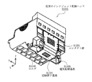
図14は、従来のインクジェット記録装置M1000の内部構造を示す斜視図である。 FIG. 14 is a perspective view showing the internal structure of a conventional ink jet recording apparatus M1000.
図15は、従来のインクジェット記録装置M1000に搭載されているインクジェット記録ヘッドH1001を、その吐出口側から見た斜視図である。 FIG. 15 is a perspective view of an ink jet recording head H1001 mounted on a conventional ink jet recording apparatus M1000 as viewed from the discharge port side.
インクジェット記録装置M1000は、図14に示すように、記録紙を給送する給送部M3022と、給送された記録紙にインクを吐出し、記録する記録部M3000とを有し、通常、図13に示すように、筐体M1005によって覆われて使用される。 As shown in FIG. 14, the ink jet recording apparatus M1000 includes a feeding unit M3022 that feeds recording paper, and a recording unit M3000 that discharges and records ink on the fed recording paper. As shown in FIG. 13, it is used covered with a casing M1005.
給送部M3022は、不図示の給送ローラを備え、所定の駆動信号に応じて、記録紙を記録部M3000に給送する。 The feeding unit M3022 includes a feeding roller (not shown), and feeds recording paper to the recording unit M3000 according to a predetermined drive signal.
記録部M3000は、インクジェット記録装置M1000の基体であるシャーシM3019に固定されているガイドシャフトM3020と、インクジェット記録ヘッドH1001(図15参照)を搭載する。 The recording unit M3000 mounts a guide shaft M3020 fixed to a chassis M3019 that is a base of the ink jet recording apparatus M1000, and an ink jet recording head H1001 (see FIG. 15).
また、ガイドシャフトM3020に沿う方向(図14中、X方向)に、往復移動自在に構成されているキャリッジM4001を具備する。そして、記録紙に対してキャリッジM4001を走査させながら、インクジェット記録ヘッドH1001の吐出口(不図示)からインクを吐出し、記録する。 Further, a carriage M4001 configured to be reciprocally movable in a direction along the guide shaft M3020 (X direction in FIG. 14) is provided. Then, ink is ejected from an ejection port (not shown) of the ink jet recording head H1001 while recording the recording paper while the carriage M4001 is scanned.
図15に示すインクジェット記録ヘッドH1001は、電気的信号に応じて、電気熱変換素子(エネルギー発生素子)を駆動させ、インクに膜沸騰を生じさせることによって、インクを吐出する。インクジェット記録ヘッドH1001は、バブルジェット(登録商標)方式のサイドシュータ型の記録ヘッドである。 The ink jet recording head H1001 shown in FIG. 15 ejects ink by driving an electrothermal conversion element (energy generating element) according to an electrical signal and causing film boiling in the ink. The ink jet recording head H1001 is a bubble shooter (registered trademark) side shooter type recording head.
インクジェット記録ヘッドH1001は、たとえば、樹脂材料で形成されたホルダH1500と、ホルダH1500の下面側に取り付けられ、吐出口(不図示)からインクを吐出するように構成されている記録素子基板H1100とを有する。また、インクジェット記録ヘッドH1001は、記録素子基板H1100に電気的信号を供給する電気配線基板H1300を有する。 The ink jet recording head H1001 includes, for example, a holder H1500 formed of a resin material, and a recording element substrate H1100 attached to the lower surface side of the holder H1500 and configured to eject ink from an ejection port (not shown). Have. Further, the ink jet recording head H1001 includes an electric wiring substrate H1300 that supplies an electric signal to the recording element substrate H1100.
ホルダH1500は、複数のインクタンク(不図示)を保持するとともに、上記キャリッジM4001(図14参照)に対して、着脱自在な形状に形成されている。 The holder H1500 holds a plurality of ink tanks (not shown) and is formed in a detachable shape with respect to the carriage M4001 (see FIG. 14).
図16は、図15に示すインクジェット記録ヘッドH1001の分解斜視図である。 FIG. 16 is an exploded perspective view of the ink jet recording head H1001 shown in FIG.
ホルダH1500の下面側には、図16に示すように、ほぼ平坦な面として形成されている吐出口部H1550が設けられ、この吐出口部H1550には、記録素子基板H1100を取り付けるための支持凹部H1501が形成されている。支持凹部H1501には、インクタンク(不図示)のインクを、記録素子基板H1100に供給するための複数のインク流路H1502が開口している。
As shown in FIG. 16, a discharge port portion H1550 formed as a substantially flat surface is provided on the lower surface side of the holder H1500, and a support recess for mounting the recording element substrate H1100 is provided in the discharge port portion H1550. H1501 is formed. A plurality of ink flow paths H1502 for supplying ink from an ink tank (not shown) to the recording element substrate H1100 are opened in the support recess H1501 .
記録素子基板H1100は、シリコン製の基板で構成され、その外形が長方形に形成されている。記録素子基板H1100には、複数の吐出口群H1101が設けられ、吐出口群H1101は、互いにほぼ等間隔で、キャリッジM4001の走査方向(図面X方向)に配置されている。各吐出口群H1101には、複数の吐出口が配列され、その配列方向は、インクジェット記録ヘッドH1001を組み立てた状態で、キャリッジの走査方向と直交する方向(図面Y方向)である。 The recording element substrate H1100 is composed of a silicon substrate, and its outer shape is rectangular. The recording element substrate H1100 is provided with a plurality of ejection port groups H1101, and the ejection port groups H1101 are arranged at substantially equal intervals in the scanning direction (X direction in the drawing) of the carriage M4001. A plurality of ejection ports are arranged in each ejection port group H1101, and the arrangement direction is a direction (Y direction in the drawing) orthogonal to the scanning direction of the carriage in a state where the inkjet recording head H1001 is assembled.
電気配線基板H1300は、たとえば可撓性を有するTABフィルムからなり、一端側が、ホルダH1500の下面に貼り付けられ、他端側は、ホルダの側面に固定されている。電気配線基板H1300の、ホルダH1500の下面に貼り付けられる側の一端には、開口部H1301が形成され、他端側には、外部の電気的接続部(不図示)と接触するコンタクト部H1350が設けられている。なお、TABフィルムの厚みは、たとえば0.12mm程度である。 The electrical wiring board H1300 is made of, for example, a flexible TAB film, one end side is attached to the lower surface of the holder H1500, and the other end side is fixed to the side surface of the holder. An opening H1301 is formed at one end of the electric wiring board H1300 that is attached to the lower surface of the holder H1500, and a contact portion H1350 that contacts an external electrical connection portion (not shown) is formed at the other end. Is provided. Note that the thickness of the TAB film is, for example, about 0.12 mm.
次に、記録素子基板H1100単体の構造と、記録素子基板H1100が取り付けられる支持凹部H1501周辺の構造とについて、より詳細に説明する。 Next, the structure of the recording element substrate H1100 alone and the structure around the support recess H1501 to which the recording element substrate H1100 is attached will be described in more detail.
図17は、図15のインクジェット記録ヘッドH1001の吐出口周辺の構造部を示す図である。 FIG. 17 is a diagram showing a structure around the discharge port of the ink jet recording head H1001 of FIG.
図17(a)は、インクジェット記録ヘッドH1001の吐出口周辺の構造部を、吐出口側から見た図であり、図17(b)は、図17(a)のA−A線における断面を示す図である。 FIG. 17A is a view of the structure around the discharge port of the inkjet recording head H1001 as viewed from the discharge port side, and FIG. 17B is a cross-sectional view taken along the line AA in FIG. FIG.
図18は、従来例における記録素子基板H1100のみを示す拡大断面図である。 FIG. 18 is an enlarged cross-sectional view showing only the recording element substrate H1100 in the conventional example.
記録素子基板H1100は、図18に示すように、複数の吐出口H1101aを有するオリフィスプレートH1115aと、インク供給口H1101bが形成されているヒータボードH1115bとが積層されている。 As shown in FIG. 18, the recording element substrate H1100 is formed by laminating an orifice plate H1115a having a plurality of ejection openings H1101a and a heater board H1115b on which ink supply openings H1101b are formed.
オリフィスプレートH1115aは、薄い板状部材で構成され、図17(a)に示すように、複数の吐出口H1101aが配列されている6列の吐出口群H1101を有する。吐出口群H1101の配置数は、ホルダH1500(図16参照)に搭載されているインクタンク(不図示)の数に対応し、各インクタンク(不図示)からのインクがそれぞれ対応する吐出口群H1101から吐出される。 The orifice plate H1115a is formed of a thin plate-like member, and as shown in FIG. 17A, has six rows of discharge port groups H1101 in which a plurality of discharge ports H1101a are arranged. The number of ejection port groups H1101 arranged corresponds to the number of ink tanks (not shown) mounted on the holder H1500 (see FIG. 16), and the ejection port groups to which the ink from each ink tank (not shown) corresponds respectively. Discharged from H1101.
ヒータボードH1115bのインク供給口H1101bは、図示しないが、図17(a)に示す吐出口群H1101と同じ方向に延びる長穴として形成されている。インク供給口H1101bは、オリフィスプレートH1115aの各吐出口群H1101毎に、1つずつ形成され、各吐出口群H1101のそれぞれの吐出口H1101aに、インクを供給できるように構成されている。 Although not shown, the ink supply port H1101b of the heater board H1115b is formed as a long hole extending in the same direction as the ejection port group H1101 shown in FIG. One ink supply port H1101b is formed for each discharge port group H1101 of the orifice plate H1115a, and is configured to be able to supply ink to each discharge port H1101a of each discharge port group H1101.
ヒータボードH1115bのオリフィスプレートH1115aが接着されている側の表面には、不図示の複数の発熱抵抗体(電気熱変換素子)が、エネルギー発生素子として設けられている。この発熱抵抗体(不図示)は、互いにほぼ等間隔で、インク供給口H1101bの両側に並んで配置されている。また、ヒータボードH1115bの同表面上には、上記発熱抵抗体に電力を供給するための配線(不図示)が引き回されている。この配線は、ヒータボードH1115b表面の長手方向の両側に設けられている電極パッド(不図示)と結線されている。 On the surface of the heater board H1115b on the side where the orifice plate H1115a is bonded, a plurality of heating resistors (electrothermal conversion elements) (not shown) are provided as energy generating elements. The heating resistors (not shown) are arranged side by side on both sides of the ink supply port H1101b at substantially equal intervals. Further, wiring (not shown) for supplying electric power to the heating resistor is routed on the same surface of the heater board H1115b. This wiring is connected to electrode pads (not shown) provided on both sides of the heater board H1115b in the longitudinal direction.
図17(a)に示すように、記録素子基板H1100が配置されている支持凹部H1501は、その外形が、記録素子基板H1100の外形よりも大きな長方形形状に形成されている。また、その深さは、図17(b)に示すように、記録素子基板H1100を支持凹部H1501内に配置したときに、記録素子基板H1100の表面が電気配線基板H1300の表面とほぼ同一面となるように調整されている。なお、この面を「吐出口面」と呼ぶ。 As shown in FIG. 17A, the support recess H1501 in which the recording element substrate H1100 is arranged is formed in a rectangular shape whose outer shape is larger than the outer shape of the recording element substrate H1100. Further, as shown in FIG. 17B, the depth of the recording element substrate H1100 is substantially the same as the surface of the electrical wiring substrate H1300 when the recording element substrate H1100 is disposed in the support recess H1501. It has been adjusted to be. This surface is called an “ejection port surface”.
記録素子基板H1100は、支持凹部H1501のほぼ中央に配置され、インク供給口H1101bと、ホルダH1500側のインク流路H1502とが連通するように接着固定される。 The recording element substrate H1100 is disposed almost at the center of the support recess H1501, and is bonded and fixed so that the ink supply port H1101b communicates with the ink flow path H1502 on the holder H1500 side.
記録素子基板H1100を支持凹部H1501内に配置すると、記録素子基板H1100の周りには、溝部H1503(図17(b)参照)が形成される。溝部H1503は、より詳細には、記録素子基板H1100の外周面と支持凹部H1501の内周面との間に形成されている。溝部H1503は、第1の封止材M1303aと第2の封止材M1303bとで充填されることによって、封止されている。第1の封止材M1303aは、記録素子基板H1100の短辺側の2辺を封止し、第2の封止材M1303bは、長辺側の2辺を封止している。 When the recording element substrate H1100 is disposed in the support recess H1501, a groove H1503 (see FIG. 17B) is formed around the recording element substrate H1100. More specifically, the groove H1503 is formed between the outer peripheral surface of the recording element substrate H1100 and the inner peripheral surface of the support recess H1501. The groove H1503 is sealed by being filled with the first sealing material M1303a and the second sealing material M1303b. The first sealing material M1303a seals two sides on the short side of the recording element substrate H1100, and the second sealing material M1303b seals two sides on the long side.
再び図16を参照し、記録素子基板H1100と電気配線基板H1300との電気的接続は、電気配線基板H1300に設けられているリードH1302を用いて行われる。リードH1302は、電気配線基板H1300に形成されている長方形の開口部H1301の長辺側の2辺に設けられている。したがって、リードH1302と記録素子基板H1100の電極パッド(不図示)とは、記録素子基板H1100の長辺側の辺で電気的に接続されている。この電気的接続は、ヒータボードH1115bの電極パッド(不図示)上にバンプを形成し、リードH1302を、TAB実装法によって実装することによって、実施可能であり、その電気的接続部(不図示)は封止材によって封止されている。 Referring to FIG. 16 again, the electrical connection between the recording element substrate H1100 and the electrical wiring substrate H1300 is performed using leads H1302 provided on the electrical wiring substrate H1300. The leads H1302 are provided on the two long sides of the rectangular opening H1301 formed in the electrical wiring board H1300. Therefore, the lead H1302 and the electrode pad (not shown) of the recording element substrate H1100 are electrically connected at the long side of the recording element substrate H1100. This electrical connection can be performed by forming bumps on the electrode pads (not shown) of the heater board H1115b and mounting the leads H1302 by the TAB mounting method, and the electrical connections (not shown). Is sealed with a sealing material.
上記のように構成されているインクジェット記録ヘッドH1001は、電気配線基板H1300のコンタクト部H1350を介して入力された電気的信号に応じて、記録素子基板H1100の発熱抵抗体(不図示)が駆動される。そして、吐出口H1101aからインクを吐出しながら記録する。 In the inkjet recording head H1001 configured as described above, a heating resistor (not shown) of the recording element substrate H1100 is driven in accordance with an electrical signal input through the contact portion H1350 of the electrical wiring substrate H1300. The Then, recording is performed while ejecting ink from the ejection port H1101a.
ここで、ヒータボードH1115bの製造時において、電気熱変換体や電気配線の膜厚のばらつき等によって、インクに気泡を生じさせるために必要な最小限の投入エネルギー(すなわち発泡しきい値エネルギー)が、インクジェット記録ヘッド毎に異なる。このために、インクジェット記録装置からの印加するエネルギーが、発泡しきい値エネルギーによらずに一定であるとすると、印加エネルギーが低すぎ、インクが正常に発泡しない。また、その逆に、印加エネルギーが高すぎ、電気熱変換体に過剰な負荷がかかり、インクジェット記録ヘッドの寿命が損なわれるという不具合が発生する。 Here, at the time of manufacturing the heater board H1115b, the minimum input energy (that is, the foaming threshold energy) necessary for generating bubbles in the ink due to variations in the film thickness of the electrothermal transducer and the electric wiring is obtained. Different for each inkjet recording head. For this reason, if the energy applied from the ink jet recording apparatus is constant regardless of the foaming threshold energy, the applied energy is too low and the ink does not foam normally. Conversely, the applied energy is too high, an excessive load is applied to the electrothermal transducer, and the life of the ink jet recording head is impaired.
そこで、従来は、インクジェット記録ヘッドの製造工程で、個々のインクジェット記録ヘッドの製造時の特性に応じて、インクジェット記録ヘッドを複数種類のランクに分けて、この情報をインクジェット記録ヘッドに記憶させる。そして、インクジェット記録装置側で、インクジェット記録ヘッドのランクを識別し、ランクに応じて、インクジェット記録ヘッドの駆動電圧や駆動パルス幅を変えることによって、安定したインク吐出が行われている。
Therefore, conventionally, in the manufacturing process of the ink jet recording head, the ink jet recording head is divided into a plurality of ranks according to the characteristics at the time of manufacturing each ink jet recording head , and this information is stored in the ink jet recording head. Then, in the ink jet recording apparatus, to identify the rank of the ink jet recording head, according to the rank, by changing the driving voltage and the driving pulse width of an ink jet recording head, stable ink ejection is performed.
インクジェット記録ヘッドのランクを、インクジェット記録装置側で識別する方法としては、例えば中継配線基板に専用の配線を設け、発泡閾値エネルギーのランクに応じて、配線の所定の部位を切断し、インクジェット記録装置との電気的接続状態を変化させる方法を用いることができる。また、特許文献2には、インクジェット記録ヘッドカートリッジに設けられた識別用突起を用いて、発泡しきい値エネルギーのランクを記憶する方法が開示されている。具体的には、製造時に個々のインクジェット記録ヘッドの発泡閾値エネルギーを求め、その発泡しきい値エネルギーに応じたランクに応じて、インクジェット記録ヘッドの識別用突起の所定の部位を切断する。そして、インクジェット記録装置側で、識別用突起の状態を識別することによって、そのインクジェット記録ヘッドのランクを読み取り、読み取ったランクに応じた最適な条件で、インクジェット記録ヘッドを駆動することが特許文献2に開示されている。
また、インクジェット記録ヘッドに、記憶素子を設け、この記憶素子に、発泡閾値エネルギーのランクに関するデータを入力し、インクジェット記録装置側で、そのデータを読み取り、読み取ったデータに応じて、インクジェット記録装置側で個々に駆動条件を変更することによって、最適な条件でインクジェット記録ヘッドを駆動することもできる。特許文献3には、製造時などに吐出試験を行って各電気熱変換体毎にパルス幅を決定し、決定したパルス幅を、インクジェット記録ヘッドのEP−ROMからなる記憶素子に記憶させ、印字を行う場合に、記憶素子から読み出されたパルス幅で駆動信号を印加することが開示されている。
The rank of the ink jet recording head, a method for identifying the ink jet recording apparatus, for example, a dedicated wiring relay wiring substrate provided, in accordance with the rank of the foam threshold energy, to cut a predetermined portion of the wiring, an ink jet recording A method of changing the electrical connection state with the apparatus can be used. Patent Document 2 discloses a method of storing the foaming threshold energy rank using an identification protrusion provided on an ink jet recording head cartridge. Specifically, the foaming threshold energy of each ink jet recording head is obtained at the time of manufacture, and a predetermined portion of the identification protrusion of the ink jet recording head is cut according to the rank corresponding to the foaming threshold energy. Patent Document 2 describes that the ink jet recording device side reads the rank of the ink jet recording head by identifying the state of the identification protrusion, and drives the ink jet recording head under optimum conditions according to the read rank. Is disclosed.
Also, a storage element is provided in the ink jet recording head, data relating to the rank of the foaming threshold energy is input to the memory element, the data is read on the ink jet recording apparatus side, and the data is read according to the read data. By changing the driving conditions individually, the ink jet recording head can be driven under optimum conditions. In Patent Document 3, a discharge test is performed at the time of manufacturing or the like to determine a pulse width for each electrothermal transducer, and the determined pulse width is stored in a storage element composed of an EP-ROM of an ink jet recording head for printing. In the case of performing the above, it is disclosed that a drive signal is applied with a pulse width read from the memory element.
また、発泡閾値エネルギーの他に、インクジェット記録装置側で、個々に駆動条件を変える必要のある特性についても、同様の手法によって、インクジェット記録装置で識別可能である。
しかし、インクジェット記録ヘッドの駆動条件を、インクジェット記録装置側で識別可能とするために、上記手段を用いると、次の問題がある。 However, if the above-described means is used to make it possible to identify the driving conditions of the ink jet recording head on the ink jet recording apparatus side, there are the following problems.
まず、一つ一つ工場出荷時に印字物を検査し、インクジェット記録ヘッドに入力する最小限のエネルギー値を測定する工程が増えるという問題がある。 First, there is a problem that the number of processes for inspecting the printed matter one by one at the time of factory shipment and measuring the minimum energy value input to the ink jet recording head increases.
そして、その情報を、記憶素子に記憶させる工程も入るので、スループットが低下するという問題がある。 Further, there is a problem that the throughput is lowered because a process for storing the information in the storage element is also included.
また、識別のための専用の配線を設け、この配線を、インクジェット記録ヘッドの特性に応じて切断する従来例では、配線を切断するための特別な工具が必要であり、作業が煩雑になるという問題がある。また、切断の際に発生した切り粉が、吐出口やインク流路内に侵入し、目詰まりの原因になるという問題がある。そして、なによりも、出荷時以降の変化に対応できないという問題がある。 In addition, in the conventional example in which a dedicated wiring for identification is provided and this wiring is cut according to the characteristics of the ink jet recording head, a special tool for cutting the wiring is necessary, and the work is complicated. There's a problem. In addition, there is a problem that chips generated at the time of cutting enter a discharge port or an ink flow path and cause clogging. Above all, there is a problem that it cannot cope with changes after shipment.
本発明は、記録ヘッドの特性のバラツキに関わらず、安定したインク滴を吐出することができ、しかも、出荷時以降の変化に対応できるインクジェット記録装置及びインクジェット記録装置の制御方法を提供することを目的とする。
The present invention, regardless of variations in the characteristics of the recording head, stable able to eject ink droplets, moreover, to provide a control method for an ink jet recording apparatus and an ink jet recording apparatus Ru can support after factory change With the goal.
本発明の記録ヘッドの駆動方法は、電気熱変換素子と、該電気熱変換素子の上方又は下方に設けられた温度検知素子と、を有する記録ヘッドの駆動方法であって、前記電気熱変換素子に供給するエネルギーを変更して前記電気熱変換素子を駆動する駆動工程と、前記電気熱変換素子の駆動時に前記温度検知素子から温度情報を取得する取得工程と、前記取得工程で取得した温度情報に基づき降温過程の温度変化を評価する評価工程と、前記評価工程の評価結果に基づき記録媒体に記録を行うときの前記電気熱変換素子を駆動するために最小限必要なエネルギーを決定する決定工程とを備えることを特徴とする。 The recording head driving method of the present invention is a recording head driving method comprising an electrothermal conversion element and a temperature detection element provided above or below the electrothermal conversion element, the electrothermal conversion element being A driving step of driving the electrothermal conversion element by changing energy supplied to the electrothermal conversion element; an acquisition step of acquiring temperature information from the temperature detection element when driving the electrothermal conversion element; and the temperature information acquired in the acquisition step And a determination step for determining a minimum energy necessary for driving the electrothermal transducer when recording on a recording medium based on an evaluation result of the evaluation step It is characterized by providing.
本発明によれば、ノズル内温度を監視し、各電気熱変換素子に印加するエネルギーを調整するので、記録ヘッドの個体差又は経時変化による吐出状態の違いがあっても、安定したインク滴を吐出することができ、しかも、出荷時以降の変化に対応できるという効果を奏する。 According to the present invention, since the temperature in the nozzle is monitored and the energy applied to each electrothermal conversion element is adjusted, stable ink droplets can be produced even if there is a difference in ejection state due to individual differences of the print heads or changes over time. It can be discharged, moreover, an effect that Ru can support after factory change.
発明を実施するための最良の形態は、次の実施例である。 The best mode for carrying out the invention is the following embodiment.
図1は、本発明の実施例1である記録ヘッド10を示す図である。 FIG. 1 is a diagram showing a recording head 10 that is Embodiment 1 of the present invention.
図1(a)は、吐出ノズルを省略した記録ヘッド10を示す断面図である。 FIG. 1A is a cross-sectional view showing the recording head 10 in which the ejection nozzle is omitted.
図1(b)は、吐出ノズルを省略した記録ヘッド10を示す平面図である。 FIG. 1B is a plan view showing the recording head 10 in which the ejection nozzle is omitted.
記録ヘッド10は、Si基板1と、蓄熱層2と、温度検知素子3と、個別配線31と、共通配線33と、層間絶縁膜4と、吐出用ヒータ5と、パシベーション膜6と、耐キャビテーション膜7とを有する。なお、吐出用ヒータ5は、電気熱変換素子の例である。
The recording head 10 includes a Si substrate 1, a heat storage layer 2, a temperature detection element 3, an
Si基板1には、熱酸化膜SiO2等からなる蓄熱層2を介して、Al、Pt、Ti、TiN、TiSi、Ta、TaN、TaSiN、TaCr、Cr、CrSiN、W等の薄膜抵抗体で構成されている温度検知素子3が形成されている。また、Si基板1には、接続配線のためのAl等の個別配線31、共通配線33と、ヒータ5と、Si基板に形成されている制御回路を接続するAl配線とが形成されている。
The Si substrate 1 is composed of thin film resistors such as Al, Pt, Ti, TiN, TiSi, Ta, TaN, TaSiN, TaCr, Cr, CrSiN, and W through a heat storage layer 2 made of a thermal oxide film SiO2 or the like. A temperature sensing element 3 is formed. Further, the Si substrate 1 is formed with
層間絶縁膜4を介して、TaSiN等の吐出用ヒータ(電気熱変換素子)5と、SiO2等のパシベーション膜6と、電気熱変換素子上の耐キャビテーション性を高めるために、Ta等の耐キャビテーション膜7とが、半導体プロセスで高密度に積層されている。
In order to enhance the cavitation resistance on the electrothermal conversion element and the discharge heater (electrothermal conversion element) 5 such as TaSiN, the passivation film 6 such as SiO 2, and the like through the
薄膜抵抗体で形成されている温度検知素子3は、吐出用ヒータ5のそれぞれの直下に、分離独立して配置されている。各温度検知素子に接続されている温度検知素子の個別配線31、共通配線33は、温度検知素子の情報を検出する検出回路の一部として構成されている。
The temperature detection element 3 formed of a thin film resistor is arranged separately and independently immediately below each
Si基板1には、熱酸化膜SiO2等からなる蓄熱層2を介して、ヒータとSi基板とに形成されている制御回路を接続するAl配線が形成されている。 On the Si substrate 1, Al wiring for connecting a control circuit formed on the heater and the Si substrate is formed via a heat storage layer 2 made of a thermal oxide film SiO 2 or the like.
また、層間絶縁膜4を介して、TaSiN等の吐出用ヒータ(電気熱変換素子)5と、SiO2等のパシベーション膜6と、電気熱変換素子との上の耐キャビテーション性を高めるために、次にようにしている。つまり、Ta等の耐キャビテーション膜7が形成されている従来の構成の蓄熱層2上に、温度検知素子3と、接続配線のためのAl等の個別配線31と、共通配線33とを成膜する。温度検知素子3は、Al、Pt、Ti、TiN、TiSi、Ta、TaN、TaSiN、TaCr、Cr、CrSiN、W等の薄膜抵抗体で形成されている。
In order to improve the cavitation resistance on the discharge heater (electrothermal conversion element) 5 such as TaSiN, the passivation film 6 such as SiO 2 and the electrothermal conversion element via the
そして、パターンニングすることによって、従来の記録ヘッド構造を変えることなく、作製することができる。したがって、工業生産上も大きな利点を有する。 Then, by patterning, it can be manufactured without changing the conventional recording head structure. Therefore, it has a great advantage in industrial production.
図2は、記録ヘッド10の変形例である記録ヘッド10aの形状を示す平面図である。 FIG. 2 is a plan view showing the shape of a recording head 10 a that is a modification of the recording head 10.
図1(b)に示す記録ヘッド10では、正方形の温度検知素子3を、ヒータ5の直下に配置してあるが、記録ヘッド10aは、スネーク形の温度検知素子3aが、ヒータ5の直下に配置されている。
In the recording head 10 shown in FIG. 1B, the square temperature detection element 3 is arranged immediately below the
図1(b)に示す記録ヘッド10では、層間絶縁膜4を介したヒータ5の平面形状を平坦に形成することができ、吐出の安定性がより容易に確保できる。
In the recording head 10 shown in FIG. 1B, the planar shape of the
図2に示すスネーク形の温度検知素子3aでは、温度検知素子3aの抵抗値を大きく設定することが容易であるので、微小の温度変化を、精度良く検出することができる。 In the snake-shaped temperature detection element 3a shown in FIG. 2, it is easy to set a large resistance value of the temperature detection element 3a, so that a minute temperature change can be detected with high accuracy.
図3は、記録ヘッド10の別の変形例である記録ヘッド10bを示す断面図である。 FIG. 3 is a cross-sectional view showing a recording head 10 b which is another modification of the recording head 10.
図1に示す記録ヘッド10では、温度検知素子3をヒータ5の直下に配置したが、図3に示す記録ヘッド10bでは、温度検知素子3bをヒータ5の直上に配置してある。図1に示す記録ヘッド10では、インクと接する耐キャビテーション膜7を平坦に形成することができる。図3に示す記録ヘッド10bでは、図1に示す記録ヘッド10に比べ、インク層との距離が近いので、インク吐出動作に伴う温度変化を、より高精度に検出することができる。
In the recording head 10 shown in FIG. 1, the temperature detection element 3 is disposed immediately below the
次に、実施例1における駆動回路構成の概要について説明する。 Next, the outline of the drive circuit configuration in the first embodiment will be described.
図4は、実施例1における駆動回路構成の概要を示す図である。 FIG. 4 is a diagram illustrating an outline of a drive circuit configuration according to the first embodiment.
吐出用ヒータ(電気熱変換素子)5は、20個単位で1つの駆動ブロックが構成され、32個の駆動ブロックが構成され、時分割で駆動される。駆動ブロックは、信号BLE0〜31によって選択され、駆動ブロック内に属する20個の吐出ヒータ5を駆動するか否かを決定する。
The discharge heater (electrothermal conversion element) 5 is composed of one drive block in units of 20 and 32 drive blocks are driven in a time-sharing manner. The drive block is selected by signals BLE0 to 31 and determines whether or not to drive the 20
信号DATAには、クロックCLKに同期して、転送データが出力され、シフトレジスタにシリアル転送される。そして、シフトレジスタに格納されているデータは、次の駆動ブロックの最初に出力される信号LTのタイミングで、ラッチに記憶される。したがって、最初の転送データに従って、実際の駆動がされるのは、その次のブロックの転送が行われるタイミングである。 Transfer data is output to the signal DATA in synchronization with the clock CLK and serially transferred to the shift register. The data stored in the shift register is stored in the latch at the timing of the signal LT output at the beginning of the next drive block. Therefore, the actual driving is performed according to the first transfer data at the timing when the next block is transferred.
ここで、転送されるデータ内容は、駆動されるブロックの番号、そのブロックで駆動される吐出用ヒータ5(電気熱変換素子)の駆動データ、アナログスイッチの選択データ、温度検知素子3のスイッチングデータである。駆動ブロックは、デコーダで、信号BLE0〜31にデコードされ、常に32個の吐出用ヒータ5のうちの1個だけが駆動される。ANDゲートの一方の入力には、20ビットの駆動データ信号が接続され、もう一方の入力には、吐出用ヒータ5を実際に駆動するタイミングを与えるパルス信号HEが接続されている。
Here, the transferred data includes the number of the block to be driven, the drive data of the discharge heater 5 (electrothermal conversion element) driven by the block, the selection data of the analog switch, and the switching data of the temperature detection element 3. It is. The drive block is decoded by the decoder into signals BLE0 to BLE, and only one of the 32
20個のビットの駆動データによって指定されたセグメントに対して、パルスHEのタイミングで駆動される。上記のように、最初に0ブロック目が駆動され、順次1、2、…が駆動され、最後に、31ブロック目の駆動が完了し、全ヒータボードの全ノズルの吐出が制御される。 The segment designated by the drive data of 20 bits is driven at the timing of the pulse HE. As described above, the 0th block is driven first, 1, 2,... Are sequentially driven, and finally the 31st block is driven, and the ejection of all nozzles of all heater boards is controlled.
次に、温度検知回路について、以下に説明する。 Next, the temperature detection circuit will be described below.
温度検知素子3の一方には、個別配線32に接続され、ON/OFF制御する第1のSW素子34が設けられ、他方は、Al共通配線によって複数の温度検知素子3が接続され、温度検知素子群を形成している。この温度検知素子群を複数構成し、各温度センサ群には、一定電流を流す定電流源、各温度検知素子群の出力を切り替えるアナログスイッチ回路や、SW素子(以下、「第2のSW素子」という)が設けられている。第1、第2のSW素子を制御する制御回路(不図示)が構成されている。温度検知素子群を選択する第2のSW素子と、各素子を制御する第1のSW素子とによって、検知する温度検知素子3が選択される。
One of the temperature detection elements 3 is connected to the
第2のSW素子を設けることによって、各検知素子群から、直接個々に温度情報を取り出す必要がなく、端子数を削減することができる。各素子を制御する制御回路において、センサBLEは、各検知素子群に1ビットずつ共通に接続されている。温度検知素子群を構成する素子数分の共通配線がなされ、信号PTENは、各素子に対応するAND回路に共通に配線されている。 By providing the second SW element, it is not necessary to directly extract temperature information from each detection element group, and the number of terminals can be reduced. In the control circuit for controlling each element, the sensor BLE is commonly connected to each detection element group by one bit. Common wiring for the number of elements constituting the temperature detection element group is made, and the signal PTEN is wired in common to AND circuits corresponding to the respective elements.
ONしたビットの出力は、アナログスイッチによって、出力する温度検知素子群が選択され、出力端子から電圧として出力される。上記構成では、温度検知素子3の少なくとも一方を共通配線化することができるので、レイアウト上もメリットがある。 The output of the bit that is turned on is selected as a temperature detection element group to be output by an analog switch and output as a voltage from the output terminal. In the above configuration, since at least one of the temperature detection elements 3 can be formed as a common wiring, there is an advantage in layout.
図5は、実施例1において、ヒータ5に印加される入力エネルギーの矩形波と温度検知素子3が検出する温度曲線の時間変化とを示す図である。
FIG. 5 is a diagram illustrating a rectangular wave of input energy applied to the
たとえば、初期温度が25℃であるときに、層間絶縁膜4の膜厚が0.95μmであり、抵抗値が360Ωのヒータ5に、20Vのパルスを0.80μs印加すると、インクは吐出口から正常に吐出する。この際における温度検知素子3が検出する温度特性が、図5に実線で示す特性である。
For example, when the initial temperature is 25 ° C., when the thickness of the
しかし、同一のヒータ5に、20Vのパルスを0.79μs印加すると、吐出口からメニスカスが突起するが、インクが吐出せずに、再び吐出口内部に移動した。このときの温度特性は、図5に点線で示す特性であることが、本願の特許出願の発明者の実験によって解明された。
However, when a pulse of 20 V was applied to the
ヒータ5に印加する電圧を固定し、パルス幅を正常にインクが吐出したときの値から漸増したときに温度検知素子3が検出する温度曲線の降温過程では、パルス印加から12μs以内で、降温速度の急激な変化が起こる。一方、パルス幅を漸減した際の温度曲線の変化は、パルス印加から12μs以内に、降温速度の急激な変化は起こっていない。
In the temperature lowering process of the temperature curve detected by the temperature detection element 3 when the voltage applied to the
次に、ヒータ5に印加する矩形波の幅が同じで、電圧値が異なる場合における温度変化を測定した。
Next, a change in temperature was measured when the width of the rectangular wave applied to the
図6は、ヒータ5に印加する矩形波の幅が同じで、電圧値が異なる場合における温度変化を測定した結果を示す図である。
FIG. 6 is a diagram illustrating a result of measuring a temperature change when the rectangular waves applied to the
図6に示す実線が、初期温度25℃のときに、層間絶縁膜4の膜厚が0.95μmで、抵抗値が360Ωのヒータ5に、20.0Vのパルスを0.80μs印加したときに、温度検知素子3が検出する温度特性である。この条件のときには、インクは、正常に吐出口から吐出した。しかし、パルス幅が0.80μsであり、印加電圧が19.8Vであるときには、インクが吐出せず、そのときの温度変化は、図6に点線で示す特性であることが分かった。
The solid line shown in FIG. 6 indicates that when the initial temperature is 25 ° C., a 20.0 V pulse is applied to the
この場合も、先ほどと同じように、ヒータ5に印加するパルス幅を固定して印加する電圧を、漸増、漸減した場合の温度変化を測定する。印加電圧を漸増した場合、インクは、正常に吐出し、降温過程での降温速度の急激な変化が、パルス印加から12μs以内で起こる。しかし、印加電圧を漸減した場合、インクは吐出せず、降温過程での降温速度の急激な変化も起こっていない。
Also in this case, as before, the temperature change is measured when the voltage applied to the
電圧をヒータ5に印加することによって発する熱エネルギー(つまり、ジュール熱)は、次式によって表現することができる。
Q=(Vl(Rheater+R配線抵抗+RMOS))2×Rheater×tパルス幅
ここで、Rheaterは、吐出用ヒータ5の抵抗値であり、R配線抵抗は、配線抵抗値であり、RMOSは、MOSのon抵抗値であり、Vは、駆動電圧である。
The thermal energy (that is, Joule heat) generated by applying a voltage to the
Q = (Vl (R heater + R wiring resistance + R MOS )) 2 × R heater × t pulse width
Here, R heater is the resistance value of the
したがって、温度センサが検出した温度曲線から、インク吐出が正常に行われるために必要最小限のジュール熱を求めることができ、上式から、印加電圧又はパルス幅を算出することができる。 Therefore, the minimum Joule heat necessary for normal ink ejection can be obtained from the temperature curve detected by the temperature sensor, and the applied voltage or pulse width can be calculated from the above equation.
このように、インク吐出可能な必要最小限のジュール熱に基づいて、印加電圧やパルス幅等、駆動条件を決定し、これによって、個体バラツキや経時変化による伝熱特性がノズル毎に異なっても、各ノズルに適した駆動条件を選択することができる。したがって、安定したインク吐出を保証することができ、しかも、過度なエネルギー印加による記録ヘッドへの負担をなくすことができる。 In this way, the drive conditions such as applied voltage and pulse width are determined based on the minimum necessary Joule heat that can eject ink, and even if the heat transfer characteristics due to individual variations and changes over time differ from nozzle to nozzle. A driving condition suitable for each nozzle can be selected. Therefore, stable ink ejection can be guaranteed, and the burden on the recording head due to excessive energy application can be eliminated.
次に、上記構成のインクジェット記録装置を、共通装置として用いるインク滴を吐出するために必要な最小限の入力エネルギーを決定する方法について説明する。 Next, a method for determining the minimum input energy necessary for ejecting ink droplets used as a common device in the ink jet recording apparatus having the above configuration will be described.
図7は、インク滴を吐出するための必要最小限の入力エネルギーを決定する動作を示すフローチャートである。 FIG. 7 is a flowchart showing an operation for determining the minimum input energy necessary for ejecting ink droplets.
図8は、実施例1において、インク滴を吐出するために必要な最小限の入力エネルギー閾値を算出する方法の説明図である。 FIG. 8 is an explanatory diagram of a method for calculating the minimum input energy threshold necessary for ejecting ink droplets in the first embodiment.
S11で、インクが正常に吐出するために十分な駆動条件を選択し、ヒータ5に印加する。S12で、そのときのノズル内温度を温度センサが測定する。S13では、S12で測定した温度変化曲線を、微分器に入力し、温度変化を時間で1階微分し、この結果を出力する。図8(b)は、このときの結果を示す図である。
In S <b> 11, a driving condition sufficient to eject ink normally is selected and applied to the
S14では、S13で得られた温度変化曲線の1階微分した値を、さらにもう一度微分器に入力することによって、温度変化を時間で2階微分した結果を出力する。この結果を、図8(c)に示す。 In S14, the value obtained by first-order differentiation of the temperature change curve obtained in S13 is further input to the differentiator to output the result of second-order temperature change differentiation. The result is shown in FIG.
S15では、S14で出力された温度変化を、時間で2階微分した曲線において、2回目に値が0になった以後の時間において、負のピークが出現するかどうかを判定する。そして、『ピークあり』と判定されれば、S16に進み、ヒータ5に入力した駆動条件を記憶手段に保存する。
In S15, it is determined whether or not a negative peak appears at a time after the value becomes zero for the second time in the curve obtained by second-order differentiation of the temperature change output in S14. If it is determined that “there is a peak”, the process proceeds to S16, and the drive condition input to the
そして、S17で、入力した駆動条件を印加した際のヒータ5が発するジュール熱エネルギーから、漸減した発熱量になるように、駆動電圧固定でパルス幅を短くする。又はパルス幅固定で駆動電圧を低下させるか等、駆動条件を選択し、ヒータ5に印加し、再びS12に戻る。そしてS15で、再び『ピークあり』と判定されれば、S16に進み、ヒータ5に入力した駆動条件を、記憶手段に上書き保存し、S17に進む。
In S17, the pulse width is shortened by fixing the driving voltage so that the heating value gradually decreases from the Joule heat energy generated by the
S15で『ピークなし』と判定されれば、S18に進み、S16で保存された値を、インク滴を吐出するための必要最小限の駆動条件であると決定する。 If “no peak” is determined in S15, the process proceeds to S18, and the value stored in S16 is determined as the minimum necessary driving condition for ejecting ink droplets.
実施例1では、最初の駆動条件を、インクが正常に吐出するのに十分な条件であるとしたが、この逆に、インク吐出が異常になるのに十分小さなものであるとしてもよい。ただし、この場合、S15での判定基準は、『ピークなし』である。また、S17では、入力した駆動条件を印加した際に、ヒータ5が発するジュール熱エネルギーから、漸増した発熱量になるように、駆動電圧固定でパルス幅を長くするか、又は、パルス幅固定で駆動電圧を増加させる等、駆動条件を選択する。S18では、S15で『ピークあり』と判定されると、そのときの駆動条件を、インク滴を吐出するための必要最小限の駆動条件であると決定する必要がある。
In the first embodiment, the initial driving condition is sufficient for the ink to be ejected normally, but conversely, it may be small enough for the ink ejection to become abnormal. However, in this case, the criterion in S15 is “no peak”. In S17, when the input driving conditions are applied, the pulse width is increased by fixing the driving voltage or the pulse width is fixed so that the heating value gradually increases from the Joule heat energy generated by the
図9は、本発明の実施例2の動作であるインク滴を吐出するために必要最小限の入力エネルギーを決定する動作を示すフローチャートである。 FIG. 9 is a flowchart showing an operation of determining the minimum input energy necessary for ejecting ink droplets, which is the operation of the second embodiment of the present invention.
S21で、インクが正常に吐出するために十分な駆動条件を選択し、ヒータ5に印加する。S22で、インクが正常に吐出すると、降温過程で降温速度の変化が急激に起こる時間から、所定時間後におけるノズル内温度、たとえば、降温速度の変化が急激に起こる時間から2μs後におけるノズル内温度Taを、温度センサ(温度検知素子3)が測定する。
In S <b> 21, a driving condition sufficient to eject ink normally is selected and applied to the
S23で、予め設定していた閾値Tthと、S22で測定した温度Taとを比較する。このときに、『Tth>Ta』であると判定されれば、S24に進み、ヒータ5に入力した駆動条件を記憶手段に保存する。S25で、入力した駆動条件を印加した際のヒータ5が発するジュール熱エネルギーに基づいて、漸減する発熱量になるように、駆動電圧固定で、パルス幅を短くする。又は、パルス幅固定で、駆動電圧を低下させる等、駆動条件を選択し、ヒータ5に印加し、再びS22に戻る。そして、S23で、再び『Tth>Ta』であると判定されれば、S24に進み、ヒータ5に入力した駆動条件を、記憶手段に上書き保存し、S25に進む。
In S23, the preset threshold value Tth is compared with the temperature Ta measured in S22. At this time, if it is determined that “Tth> Ta”, the process proceeds to S24, and the drive condition input to the
S23で、『Ta>Tth』であると判定されると、S26に進み、S24で、保存された値を、インク滴を吐出するための必要最小限の駆動条件であると決定する。 If it is determined in S23 that “Ta> Tth”, the process proceeds to S26, and in S24, the stored value is determined as the minimum necessary driving condition for ejecting ink droplets.
実施例2でも、最初の駆動条件が、インクが正常に吐出するために十分なものであるという駆動条件であるが、この逆に、インク吐出が異常となるために十分に小さな条件であるとしてもよい。ただし、この場合、S23での判定基準は、『Ta>Tth』であり、S25では、入力した駆動条件を印加した際のヒータ5が発するジュール熱エネルギーから漸増した発熱量になるように、駆動電圧固定でパルス幅を長くする。又は、パルス幅固定で、駆動電圧を増加させる等、駆動条件を選択する。そして、S26では、S23において、『Tth>Ta』であると判定された場合、そのときの駆動条件を、インク滴を吐出するための必要最小限の駆動条件であると決定する必要がある。
Also in the second embodiment, the initial driving condition is a driving condition that is sufficient for the normal ejection of ink, but conversely, it is assumed that the condition is sufficiently small because the ink ejection becomes abnormal. Also good. However, in this case, the determination criterion in S23 is “Ta> Tth”, and in S25, driving is performed so that the heating value gradually increases from the Joule heat energy generated by the
図10は、本発明の実施例3の動作であるインク滴を吐出するために必要最小限の入力エネルギーを決定する動作を示すフローチャートである。 FIG. 10 is a flowchart showing an operation of determining the minimum input energy necessary for ejecting ink droplets, which is the operation of the third embodiment of the present invention.
S31で、インクが正常に吐出するのに十分な駆動条件を選択し、ヒータ5に印加する。そして、S32で、所定時間範囲内のノズル内温度の値を積分する。
In S <b> 31, a driving condition sufficient for normal ink ejection is selected and applied to the
上記「所定時間範囲」は、開始時間が、ヒータ5に駆動電圧が印加されるタイミングからインクが正常に吐出した場合、降温過程で降温速度の変化が急激に起こるタイミングの間である。また、上記「所定時間範囲」は、終了時間が吐出に伴う共通液室側からのインク再充填が完全に終了するタイミングから、次の駆動信号が入力されるまでの間である。
The “predetermined time range” is a timing at which the start time is a time when the temperature drop rate changes rapidly in the temperature drop process when the ink is normally ejected from the timing when the drive voltage is applied to the
たとえば、駆動信号がヒータ5に印加されてから6.0μsのタイミングから、実施例1で用いた記録ヘッド構造において、共通液室からの再充填が終わる間での時間であるヒータ5のonから15μs後までの範囲である。
For example, from the timing of 6.0 μs after the drive signal is applied to the
次に、S33で、予め設定していた閾値Athと、S32で測定した積分値Aaとを比較する。このときに、『Ath>Aa』であると判定されれば、S34に進み、ヒータ5に入力した駆動条件を記憶手段に保存する。そして、S35で、入力した駆動条件を印加した際のヒータ5が発するジュール熱エネルギーから漸減した発熱量になるように、駆動電圧固定でパルス幅を短くする。又は、パルス幅固定で、駆動電圧を低下させる等、駆動条件を選択し、ヒータ5に印加し、再び、S32に戻る。そして、S33で、再び『Ath>Aa』であると判定されれば、S34に進み、ヒータ5に入力した駆動条件を記憶手段に上書き保存し、そしてS35に進む。
Next, in S33, a preset threshold Ath is compared with the integrated value Aa measured in S32. At this time, if it is determined that “Ath> Aa”, the process proceeds to S34, and the drive condition input to the
S33で、『Aa>Ath』であると判定されれば、S36に進み、S34で、保存された値を、インク滴を吐出するための必要最小限の駆動条件であると決定する。 If it is determined in S33 that “Aa> Ath”, the process proceeds to S36, and in S34, the stored value is determined as the minimum necessary driving condition for ejecting ink droplets.
実施例1では、最初の駆動条件を、インクが正常に吐出するのに十分な条件であるとしたが、これとは逆に、インク吐出が異常となる駆動条件を、インクが正常に吐出するために十分小さな条件であるとしてもよい。ただし、この場合、S33での判定基準は、『Aa>Ath』であり、S35では、入力した駆動条件を印加した際のヒータ5が発するジュール熱エネルギーから漸増した発熱量になるように、駆動電圧固定でパルス幅を長くする。又は、パルス幅固定で駆動電圧を増加させる駆動条件を選択する。そして、S36では、S33で『Ath>Aa』であると判定された場合、そのときの駆動条件を、インク滴を吐出するための必要最小限の駆動条件であると決定する必要がある。
In the first embodiment, the first driving condition is sufficient for the ink to be ejected normally. On the contrary, the ink is ejected normally under the driving condition in which the ink ejection is abnormal. Therefore, it may be a sufficiently small condition. However, in this case, the determination criterion in S33 is “Aa> Ath”, and in S35, driving is performed so that the heating value gradually increases from the Joule heat energy generated by the
実施例1〜3では、ヒータ5のそれぞれの直下又は直上に配置されている温度センサ一つ一つから、温度情報を出力する。
In the first to third embodiments, temperature information is output from each of the temperature sensors arranged immediately below or immediately above the
本発明の実施例4は、駆動ブロック内の温度センサ群の中から、1つだけ温度情報を出力し、この出力された温度情報に基づいて、インク滴を吐出するために必要最小限の駆動条件を決定する。 In the fourth embodiment of the present invention, only one piece of temperature information is output from the temperature sensor group in the drive block, and the minimum drive required for ejecting ink droplets based on the output temperature information. Determine the conditions.
実施例4によれば、検出するデータ量が少ないので、判定処理スピードが向上する。
According to the fourth embodiment, since the amount of data to be detected is small, the determination processing speed is improved.
図11は、本発明の実施例5である記録ヘッド10cを示す図である。
FIG. 11 is a diagram showing a recording head 10c that is
記録ヘッド10cは、1つの駆動ブロック内のヒータ群のどれか1つのヒータ5の直下又は直上だけに温度センサを配置し、この温度検知素子3cが測定した温度情報から、インク滴を吐出するための必要最小限の駆動条件を決定する実施例である。
In the recording head 10c, a temperature sensor is disposed just below or just above any one of the
記録ヘッド10cは、1つの駆動ブロック内のヒータ群に属する1つのヒータ5の直下又は直上だけに、温度検知素子3cを配置し、温度検知素子3cが測定した温度情報に基づいて、インク滴を吐出するために必要最小限の駆動条件を決定する実施例である。
The recording head 10c has a temperature detection element 3c arranged just below or just above one
実施例5によれば、温度変化に対する応答が鈍るが、温度検知素子3cが配置されていない部分は、ヒータ5の平面形状を平坦に形成することができ、吐出の安定性をより容易に確保することができる。また、実施例5によれば、検出するデータ量が少ないので、処理スピードが向上する。
According to the fifth embodiment, the response to the temperature change is dull, but in the portion where the temperature detection element 3c is not disposed, the planar shape of the
図12は、本発明の実施例6である記録ヘッド10dを示す図である。 FIG. 12 shows a recording head 10d that is Embodiment 6 of the present invention.
実施例6である記録ヘッド10dは、図12に示すように、1つの駆動ブロック内のヒータ群に属するヒータ5の領域を覆う程度の大きさの温度検知素子3dを、ヒータ5の直上又は直下に配置する実施例である。そして、記録ヘッド10dは、この温度検知素子3dが測定した温度情報から、インク滴を吐出するための必要最小限の駆動条件を決定する実施例である。
As illustrated in FIG. 12, the recording head 10 d according to the sixth embodiment includes a temperature detection element 3 d having a size enough to cover the area of the
実施例6によれば、温度変化に対する応答が鈍るが、ヒータ5の平面形状を損なわないように温度検知素子3dのサイズが大きいので、吐出の安定性を、容易に確保することができ、さらに、検出するデータ量が少ないので、処理スピードが向上する。
According to the sixth embodiment, the response to the temperature change is dull, but since the size of the temperature detecting element 3d is large so as not to impair the planar shape of the
実施例1〜6において、インク滴を吐出するための必要最小限のエネルギー決定手段は、前の印字が終わり、次の印字が始まるまでの間に、インク滴を吐出するための必要最小限のエネルギーを決定する。しかし、たとえば、記録に備えてインクをリフレッシュするための予備吐出処理を行っている際に、インク滴を吐出するための必要最小限のエネルギー決定手段が、インク滴を吐出するための必要最小限のエネルギーを決定するようにしてもよい。 In the first to sixth embodiments, the minimum energy determining means for ejecting ink droplets is the minimum necessary for ejecting ink droplets between the end of the previous printing and the start of the next printing. Determine energy. However, for example, when a preliminary ejection process for refreshing ink is performed in preparation for recording, the minimum energy determining means for ejecting ink drops is the minimum necessary for ejecting ink drops. The energy of may be determined.
上記実施例の印字時の駆動条件を決定する場合、たとえば、以上のようにして求めたインク滴を吐出するための必要最小限のエネルギー値の1.20倍になるように、駆動電圧、パルス幅を設定するようにしてもよい。 When determining the driving conditions at the time of printing in the above embodiment, for example, the driving voltage and the pulse are set so as to be 1.20 times the minimum necessary energy value for discharging the ink droplets obtained as described above. The width may be set.
さらに、記録装置が記録できるプリント材の最大幅に対応した長さを有するフルラインタイプの記録ヘッドにおいて、複数記録ヘッドの組合せによって、その記録ヘッドの長さを満たすようにしてもよい。また、一体的に形成されている1個の記録ヘッドとして、その記録ヘッドの長さを構成するようにしてもよい。 Further, in a full-line type recording head having a length corresponding to the maximum width of the printing material that can be recorded by the recording apparatus, the length of the recording head may be satisfied by a combination of a plurality of recording heads. Further, the length of the recording head may be configured as one recording head formed integrally.
さらに、シリアルタイプのものでも、装置本体に固定されている記録ヘッド、又は装置本体に装着されることによって、装置本体との電気的な接続や、装置本体からのインクの供給が可能になる交換自在のチップタイプの記録ヘッドを用いてもよい。また、記録ヘッド自体に一体的にインクタンクが設けられているカートリッジタイプの記録ヘッドを用いてもよい。 Furthermore, even for the serial type, replacement that enables electrical connection with the apparatus main body and supply of ink from the apparatus main body by being mounted on the recording head fixed to the apparatus main body or the apparatus main body. A free chip type recording head may be used. Further, a cartridge type recording head in which an ink tank is integrally provided in the recording head itself may be used.
また、上記実施例の記録装置の構成として、記録ヘッドの吐出回復手段、予備的な補助手段等を付加することは、本発明の効果を一層安定できるので、好ましい。 Further, it is preferable to add a recording head ejection recovery means, a preliminary auxiliary means, and the like as the configuration of the recording apparatus of the above embodiment because the effects of the present invention can be further stabilized.
上記付加手段は、記録ヘッドに対してのキャッピング手段、クリーニング手段、加圧又は吸引手段、吐出用ヒータ5又はこれとは別の加熱素子又はこれらの組合せを用いて加熱を行う予備加熱手段、記録とは別の吐出を行う予備吐出手段である。
The additional means includes a capping means for the recording head, a cleaning means, a pressurizing or suction means, a preheating means for performing heating using a
つまり、上記実施例は、複数の電気熱変換素子と、上記電気熱変換素子の直上又は直下に配置されている温度検知素子と、上記温度検知素子に接続され、温度を検出する検出回路とを具備する。上記実施例は、駆動波形に応答して、上記電気熱変換素子の熱エネルギーをインクに作用させ、吐出口からインクを吐出させる記録ヘッドである。また、上記実施例は、上記駆動波形の印加エネルギーを漸増又は漸減し、上記漸増、漸減のそれぞれにおいて温度情報として、上記温度検知素子の電圧変化を測定し、記憶装置に記憶する電圧変化測定工程を有する。さらに、上記実施例は、上記測定された電圧変化に基づいて、インク滴を吐出するために必要な最小限の入力エネルギーを決定し、記憶装置に記憶する最小限入力エネルギー決定工程を有するインクジェット記録装置の制御方法の例である。 That is, the embodiment includes a plurality of electrothermal conversion elements, a temperature detection element disposed immediately above or immediately below the electrothermal conversion element, and a detection circuit that is connected to the temperature detection element and detects a temperature. It has. The above-described embodiment is a recording head that causes thermal energy of the electrothermal conversion element to act on ink in response to a drive waveform and ejects ink from an ejection port. In the above embodiment, the applied energy of the drive waveform is gradually increased or decreased, and the voltage change measurement step of measuring the voltage change of the temperature detection element as temperature information in each of the gradual increase and decrease and storing it in the storage device. Have Further, in the above-mentioned embodiment, the minimum input energy determining step for determining the minimum input energy necessary for ejecting the ink droplet based on the measured voltage change and storing it in the storage device is performed. It is an example of the control method of an apparatus.
この場合、上記複数の温度検知素子を、順次選択し、全bitの温度情報を測定し、インク滴を吐出するために必要な最小限の入力エネルギーを決定する。また、上記電圧変化測定工程は、上記複数の電気熱変換素子と上記複数の温度検知素子とを複数のブロックに分け、ブロック毎に、1つの上記温度検知素子によって温度情報を測定する工程である。さらに、上記最小限入力エネルギー決定工程では、温度検知素子が検出する温度曲線の降温過程において、温度曲線の傾き変化を検出することによって、ノズル毎にインク吐出が可能な入力エネルギーと、インクが吐出しなくなる入力エネルギーとの閾値を測定する。
しかも、上記最小限入力エネルギー決定工程は、上記温度検知素子が検出する温度曲線の降温過程において、インクが正常に吐出した場合、降温過程で降温速度の変化が急激に起こるタイミング以降から、所定時間経過後の温度を閾値と比較する工程である。これによって、インク吐出が可能な入力エネルギーと、インクが吐出しなくなる入力エネルギーとの閾値を、ノズル毎に、測定する。
In this case, the plurality of temperature detection elements are sequentially selected, temperature information of all bits is measured, and the minimum input energy necessary for ejecting ink droplets is determined. The voltage change measurement step is a step of dividing the plurality of electrothermal conversion elements and the plurality of temperature detection elements into a plurality of blocks, and measuring temperature information by one temperature detection element for each block. . Further, in the minimum input energy determination step, the input energy that allows ink discharge for each nozzle and the ink discharge are detected by detecting a change in the slope of the temperature curve in the temperature falling process of the temperature curve detected by the temperature detection element. Measure the threshold with the input energy that does not.
In addition, the minimum input energy determination step is performed for a predetermined time after the timing when the temperature decrease rate suddenly changes in the temperature decrease process when the ink is normally ejected in the temperature decrease process of the temperature curve detected by the temperature detection element. This is a step of comparing the temperature after elapse with a threshold value. In this way, the threshold value of the input energy capable of ejecting ink and the input energy at which ink cannot be ejected is measured for each nozzle.
最小限入力エネルギー決定工程は、上記温度検知素子が検出する温度曲線の降温過程において、インクが正常に吐出した場合、降温過程で、降温速度の変化が急激に起こるタイミング以降から、所定時間範囲内の検出温度を積分した値を、参照値と比較する。これによって、インク吐出が可能な入力エネルギーと、インクが吐出しなくなる入力エネルギーとの閾値とを、ノズル毎に測定する。 The minimum input energy determination process is performed within a predetermined time range from the time when the temperature decrease rate suddenly changes in the temperature decrease process when the ink is normally discharged in the temperature decrease process of the temperature curve detected by the temperature detection element. The value obtained by integrating the detected temperature is compared with the reference value. Thereby, the threshold value of the input energy capable of ejecting ink and the input energy at which ink cannot be ejected is measured for each nozzle.
また、上記実施例を装置の発明として把握することができる。つまり、上記実施例は、複数の電気熱変換素子と、上記電気熱変換素子の直上又は直下に配置されている温度検知素子と、上記温度検知素子に接続され、温度を検出する検出回路とを具備する。また、上記実施例は、駆動波形に応答して上記電気熱変換素子の熱エネルギーをインクに作用させ、吐出口からインクを吐出させる記録ヘッドである。さらに、上記実施例は、上記駆動波形の印加エネルギーを漸増又は漸減し、上記漸増、漸減のそれぞれにおいて温度情報として、上記温度検知素子の電圧変化を測定する電圧変化測定手段を有する。しかも、上記実施例は、上記測定された電圧変化に基づいて、インク滴を吐出するために必要な最小限の入力エネルギーを決定する最小限入力エネルギー決定手段を有するインクジェット記録装置の例である。
Moreover, the said Example can be grasped | ascertained as invention of an apparatus. That is, the embodiment includes a plurality of electrothermal conversion elements, a temperature detection element disposed immediately above or immediately below the electrothermal conversion element, and a detection circuit that is connected to the temperature detection element and detects a temperature. It has. Further, the above-described embodiment is a recording head that causes thermal energy of the electrothermal conversion element to act on ink in response to a driving waveform and ejects ink from an ejection port. Further, the embodiment includes voltage change measuring means for gradually increasing or gradually decreasing the applied energy of the drive waveform and measuring the voltage change of the temperature detecting element as temperature information in each of the gradually increasing and gradually decreasing. Moreover, the above embodiment is an example of an ink jet recording apparatus having a minimum input energy determining means for determining a minimum input energy necessary for ejecting ink droplets based on the measured voltage change.
10、10a、10c、10d…記録ヘッド、
1…Si基板、
2…蓄熱層、
3、3a、3b、3c、3d…温度検知素子、
4…層間絶縁膜、
5…吐出用ヒータ、
6…パシベーション膜、
7…耐キャビテーション膜、
31、32…温度検知素子の個別配線、
33…Al共通配線。
10, 10a, 10c, 10d ... recording head,
1 ... Si substrate,
2 ... heat storage layer,
3, 3a, 3b, 3c, 3d ... temperature sensing element,
4 ... interlayer insulating film,
5 ... Discharge heater,
6 ... Passivation film,
7 ... Anti-cavitation film,
31, 32 ... Individual wiring of the temperature detection element,
33 ... Al common wiring.
Claims (6)
前記電気熱変換素子に供給するエネルギーを変更して前記電気熱変換素子を駆動する駆動工程と、
前記電気熱変換素子の駆動時に前記温度検知素子から温度情報を取得する取得工程と、
前記取得工程で取得した温度情報に基づき降温過程の温度変化を評価する評価工程と、
前記評価工程の評価結果に基づき記録媒体に記録を行うときの前記電気熱変換素子を駆動するために最小限必要なエネルギーを決定する決定工程と、
を備えることを特徴とする記録ヘッドの駆動方法。 A method for driving a recording head, comprising: an electrothermal conversion element; and a temperature detection element provided above or below the electrothermal conversion element,
A driving step of driving the electrothermal conversion element by changing energy supplied to the electrothermal conversion element;
An acquisition step of acquiring temperature information from the temperature detection element when driving the electrothermal conversion element;
An evaluation step for evaluating a temperature change in the temperature lowering process based on the temperature information acquired in the acquisition step;
A determining step for determining a minimum energy necessary for driving the electrothermal transducer when recording on a recording medium based on an evaluation result of the evaluation step;
A drive method for a recording head, comprising:
前記電気熱変換素子に供給するエネルギーを変更して前記電気熱変換素子を駆動する駆動手段と、
前記電気熱変換素子の駆動時に前記温度検知素子から温度情報を取得する取得手段と、
前記取得手段で取得した温度情報に基づき降温過程の温度変化を評価する評価手段と、
前記評価手段の評価結果に基づき記録媒体に記録を行うときの前記電気熱変換素子を駆動するために最小限必要なエネルギーを決定する決定手段と、
を備えることを特徴とする記録装置。
In a recording apparatus that performs recording on a recording medium using a recording head having an electrothermal conversion element and a temperature detection element provided above or below the electrothermal conversion element,
Driving means for driving the electrothermal conversion element by changing energy supplied to the electrothermal conversion element;
Acquisition means for acquiring temperature information from the temperature detection element when the electrothermal conversion element is driven;
Evaluation means for evaluating the temperature change in the temperature lowering process based on the temperature information acquired by the acquisition means;
Determining means for determining a minimum energy required to drive the electrothermal transducer when recording on a recording medium based on the evaluation result of the evaluating means;
A recording apparatus comprising:
Priority Applications (4)
| Application Number | Priority Date | Filing Date | Title |
|---|---|---|---|
| JP2007118634A JP5161480B2 (en) | 2007-04-27 | 2007-04-27 | Ink jet recording apparatus and control method of ink jet recording apparatus |
| US12/101,647 US8075101B2 (en) | 2007-04-27 | 2008-04-11 | Recording head driving method and recording apparatus |
| CN2008100892554A CN101293424B (en) | 2007-04-27 | 2008-04-25 | Method for driving record head and recording device |
| US13/296,081 US8197021B2 (en) | 2007-04-27 | 2011-11-14 | Recording head driving method and recording apparatus |
Applications Claiming Priority (1)
| Application Number | Priority Date | Filing Date | Title |
|---|---|---|---|
| JP2007118634A JP5161480B2 (en) | 2007-04-27 | 2007-04-27 | Ink jet recording apparatus and control method of ink jet recording apparatus |
Publications (3)
| Publication Number | Publication Date |
|---|---|
| JP2008273013A JP2008273013A (en) | 2008-11-13 |
| JP2008273013A5 JP2008273013A5 (en) | 2012-03-01 |
| JP5161480B2 true JP5161480B2 (en) | 2013-03-13 |
Family
ID=39886434
Family Applications (1)
| Application Number | Title | Priority Date | Filing Date |
|---|---|---|---|
| JP2007118634A Active JP5161480B2 (en) | 2007-04-27 | 2007-04-27 | Ink jet recording apparatus and control method of ink jet recording apparatus |
Country Status (3)
| Country | Link |
|---|---|
| US (2) | US8075101B2 (en) |
| JP (1) | JP5161480B2 (en) |
| CN (1) | CN101293424B (en) |
Families Citing this family (10)
| Publication number | Priority date | Publication date | Assignee | Title |
|---|---|---|---|---|
| JP5161480B2 (en) * | 2007-04-27 | 2013-03-13 | キヤノン株式会社 | Ink jet recording apparatus and control method of ink jet recording apparatus |
| JP5404022B2 (en) * | 2008-12-18 | 2014-01-29 | キヤノン株式会社 | Discharge state judgment method |
| JP2011189707A (en) * | 2010-03-16 | 2011-09-29 | Canon Inc | Recording apparatus and determining method of ejection condition |
| JP5498281B2 (en) * | 2010-07-05 | 2014-05-21 | キヤノン株式会社 | Head substrate, recording head using the head substrate, and recording apparatus using the recording head |
| US9108448B1 (en) | 2014-08-06 | 2015-08-18 | Funai Electric Co., Ltd. | Temperature control circuit for an inkjet printhead |
| CN110850910B (en) * | 2018-08-20 | 2021-07-20 | 浙江宇视科技有限公司 | Heating control method and device and electronic equipment |
| JP7229700B2 (en) * | 2018-08-24 | 2023-02-28 | キヤノン株式会社 | LIQUID EJECTION HEAD AND MANUFACTURING METHOD THEREOF |
| JP7148379B2 (en) * | 2018-12-06 | 2022-10-05 | キヤノン株式会社 | Recording device and method for determining minimum ejection energy |
| JP7500286B2 (en) | 2019-07-09 | 2024-06-17 | キヤノン株式会社 | Recording device |
| JP7465084B2 (en) * | 2019-12-18 | 2024-04-10 | キヤノン株式会社 | Element substrate, liquid ejection head, and recording apparatus |
Family Cites Families (9)
| Publication number | Priority date | Publication date | Assignee | Title |
|---|---|---|---|---|
| US5714989A (en) * | 1993-11-22 | 1998-02-03 | Hewlett-Packard Company | Inkdrop-volume test using heat-flow effects, for thermal-inkjet printers |
| JPH11192724A (en) * | 1997-12-29 | 1999-07-21 | Canon Inc | Ink jet printer and method for judging presence or absence of ink |
| US6474772B1 (en) * | 2001-07-17 | 2002-11-05 | Hewlett-Packard Company | Method of determining thermal turn on energy |
| JP3530843B2 (en) * | 2001-12-10 | 2004-05-24 | キヤノン株式会社 | INK JET PRINTING APPARATUS, METHOD OF DETECTING TEMPERATURE CHARACTERISTICS OF INK JET PRINT HEAD, AND METHOD OF JUDGING DISCHARGE STATE OF INK JET PRINT HEAD |
| JP4441244B2 (en) | 2003-12-01 | 2010-03-31 | キヤノン株式会社 | Inkjet recording head and inkjet recording apparatus |
| JP4208869B2 (en) * | 2005-09-09 | 2009-01-14 | キヤノン株式会社 | Inkjet recording apparatus and inkjet recording method |
| JP4827625B2 (en) * | 2006-06-14 | 2011-11-30 | キヤノン株式会社 | Recording head ejection inspection method and recording apparatus |
| JP4890960B2 (en) * | 2006-06-19 | 2012-03-07 | キヤノン株式会社 | Recording device |
| JP5161480B2 (en) * | 2007-04-27 | 2013-03-13 | キヤノン株式会社 | Ink jet recording apparatus and control method of ink jet recording apparatus |
-
2007
- 2007-04-27 JP JP2007118634A patent/JP5161480B2/en active Active
-
2008
- 2008-04-11 US US12/101,647 patent/US8075101B2/en not_active Expired - Fee Related
- 2008-04-25 CN CN2008100892554A patent/CN101293424B/en active Active
-
2011
- 2011-11-14 US US13/296,081 patent/US8197021B2/en not_active Expired - Fee Related
Also Published As
| Publication number | Publication date |
|---|---|
| US8197021B2 (en) | 2012-06-12 |
| US20080266362A1 (en) | 2008-10-30 |
| CN101293424B (en) | 2010-12-08 |
| US8075101B2 (en) | 2011-12-13 |
| US20120062631A1 (en) | 2012-03-15 |
| CN101293424A (en) | 2008-10-29 |
| JP2008273013A (en) | 2008-11-13 |
Similar Documents
| Publication | Publication Date | Title |
|---|---|---|
| JP5161480B2 (en) | Ink jet recording apparatus and control method of ink jet recording apparatus | |
| JP4137088B2 (en) | Head substrate, recording head, head cartridge, recording apparatus, and information input / output method | |
| US5576745A (en) | Recording apparatus having thermal head and recording method | |
| JP3143549B2 (en) | Substrate for thermal recording head, inkjet recording head using the substrate, inkjet cartridge, inkjet recording apparatus, and method of driving recording head | |
| US7722148B2 (en) | Liquid discharge head and liquid discharge apparatus using liquid discharge head | |
| US6866359B2 (en) | Ink jet printhead quality management system and method | |
| JP5147282B2 (en) | Inkjet recording substrate, recording head including the substrate, and recording apparatus | |
| JP5078529B2 (en) | Ink jet recording head and ink jet recording apparatus including the same | |
| EP1778497B1 (en) | Ground structure for temperature-sensing resistor noise reduction | |
| EP0593041B1 (en) | Ink jet recording apparatus | |
| JP4596757B2 (en) | Recording head test equipment | |
| JP3442027B2 (en) | Ink jet recording head and ink jet recording apparatus | |
| US6582045B2 (en) | Printing apparatus and printing control method | |
| JP2675163B2 (en) | Ink remaining amount detecting device, ink jet head cartridge having the remaining ink amount detecting device, and ink jet recording device equipped with the cartridge | |
| US6799837B1 (en) | Ink jet printing apparatus with ink level detection | |
| JP2011189707A (en) | Recording apparatus and determining method of ejection condition | |
| JP6552692B2 (en) | Element substrate, liquid discharge head, and recording apparatus | |
| JP2021094805A (en) | Element substrate, liquid ejection head, and recording apparatus | |
| JP4974664B2 (en) | RECORDING HEAD SUBSTRATE, RECORDING HEAD OR HEAD CARTRIDGE USING THE SUBSTRATE, AND RECORDING DEVICE USING THE RECORDING HEAD | |
| JP3372834B2 (en) | Ink jet recording head, ink jet recording apparatus, and substrate for ink jet recording head | |
| JP2011189708A (en) | Recording apparatus and determining method of ejection condition | |
| JP2001232814A (en) | Substrate for ink jet head, ink jet head, ink jet cartridge and ink jet recorder | |
| JP3728123B2 (en) | Inkjet recording apparatus and driving method of inkjet recording apparatus | |
| JP3190184B2 (en) | Recording apparatus and recording apparatus correction method | |
| JP2004009491A (en) | Ink state sensing mechanism |
Legal Events
| Date | Code | Title | Description |
|---|---|---|---|
| A521 | Written amendment |
Free format text: JAPANESE INTERMEDIATE CODE: A523 Effective date: 20100426 |
|
| A621 | Written request for application examination |
Free format text: JAPANESE INTERMEDIATE CODE: A621 Effective date: 20100426 |
|
| A521 | Written amendment |
Free format text: JAPANESE INTERMEDIATE CODE: A523 Effective date: 20120116 |
|
| A131 | Notification of reasons for refusal |
Free format text: JAPANESE INTERMEDIATE CODE: A131 Effective date: 20121012 |
|
| A521 | Written amendment |
Free format text: JAPANESE INTERMEDIATE CODE: A523 Effective date: 20121029 |
|
| TRDD | Decision of grant or rejection written | ||
| A01 | Written decision to grant a patent or to grant a registration (utility model) |
Free format text: JAPANESE INTERMEDIATE CODE: A01 Effective date: 20121116 |
|
| A61 | First payment of annual fees (during grant procedure) |
Free format text: JAPANESE INTERMEDIATE CODE: A61 Effective date: 20121214 |
|
| R151 | Written notification of patent or utility model registration |
Ref document number: 5161480 Country of ref document: JP Free format text: JAPANESE INTERMEDIATE CODE: R151 |
|
| FPAY | Renewal fee payment (event date is renewal date of database) |
Free format text: PAYMENT UNTIL: 20151221 Year of fee payment: 3 |
|
| RD03 | Notification of appointment of power of attorney |
Free format text: JAPANESE INTERMEDIATE CODE: R3D03 |