JP5160902B2 - 4-degree-of-freedom high-speed parallel robot - Google Patents
4-degree-of-freedom high-speed parallel robot Download PDFInfo
- Publication number
- JP5160902B2 JP5160902B2 JP2007555647A JP2007555647A JP5160902B2 JP 5160902 B2 JP5160902 B2 JP 5160902B2 JP 2007555647 A JP2007555647 A JP 2007555647A JP 2007555647 A JP2007555647 A JP 2007555647A JP 5160902 B2 JP5160902 B2 JP 5160902B2
- Authority
- JP
- Japan
- Prior art keywords
- degree
- movable platform
- parallel robot
- speed parallel
- arm members
- Prior art date
- Legal status (The legal status is an assumption and is not a legal conclusion. Google has not performed a legal analysis and makes no representation as to the accuracy of the status listed.)
- Expired - Fee Related
Links
Images


Classifications
-
- B—PERFORMING OPERATIONS; TRANSPORTING
- B25—HAND TOOLS; PORTABLE POWER-DRIVEN TOOLS; MANIPULATORS
- B25J—MANIPULATORS; CHAMBERS PROVIDED WITH MANIPULATION DEVICES
- B25J17/00—Joints
- B25J17/02—Wrist joints
-
- B—PERFORMING OPERATIONS; TRANSPORTING
- B25—HAND TOOLS; PORTABLE POWER-DRIVEN TOOLS; MANIPULATORS
- B25J—MANIPULATORS; CHAMBERS PROVIDED WITH MANIPULATION DEVICES
- B25J17/00—Joints
- B25J17/02—Wrist joints
- B25J17/0258—Two-dimensional joints
- B25J17/0266—Two-dimensional joints comprising more than two actuating or connecting rods
-
- B—PERFORMING OPERATIONS; TRANSPORTING
- B25—HAND TOOLS; PORTABLE POWER-DRIVEN TOOLS; MANIPULATORS
- B25J—MANIPULATORS; CHAMBERS PROVIDED WITH MANIPULATION DEVICES
- B25J9/00—Programme-controlled manipulators
- B25J9/003—Programme-controlled manipulators having parallel kinematics
- B25J9/0045—Programme-controlled manipulators having parallel kinematics with kinematics chains having a rotary joint at the base
- B25J9/0051—Programme-controlled manipulators having parallel kinematics with kinematics chains having a rotary joint at the base with kinematics chains of the type rotary-universal-universal or rotary-spherical-spherical, e.g. Delta type manipulators
-
- Y—GENERAL TAGGING OF NEW TECHNOLOGICAL DEVELOPMENTS; GENERAL TAGGING OF CROSS-SECTIONAL TECHNOLOGIES SPANNING OVER SEVERAL SECTIONS OF THE IPC; TECHNICAL SUBJECTS COVERED BY FORMER USPC CROSS-REFERENCE ART COLLECTIONS [XRACs] AND DIGESTS
- Y10—TECHNICAL SUBJECTS COVERED BY FORMER USPC
- Y10T—TECHNICAL SUBJECTS COVERED BY FORMER US CLASSIFICATION
- Y10T74/00—Machine element or mechanism
- Y10T74/20—Control lever and linkage systems
- Y10T74/20207—Multiple controlling elements for single controlled element
- Y10T74/20305—Robotic arm
- Y10T74/20317—Robotic arm including electric motor
Abstract
Description
本発明のロボットは、対応する工具を支持するプラットフォームを4自由度(3自由度の並進運動または平行移動と、垂直軸についての1自由度回転)で、いずれの方向にもきわめて高加速、高速で移動させることを目的としている。 The robot of the present invention has a platform supporting the corresponding tool with 4 degrees of freedom (3 degrees of freedom translation or translation and rotation with 1 degree of freedom about the vertical axis) and extremely high acceleration and high speed in any direction. It is intended to be moved with.
本発明の他の目的は、ロボットのアクチュエータを対称に配置し、可動範囲全体にわたる均質なパフォーマンスと高い剛性とを実現することである。 Another object of the present invention is to arrange the actuators of the robot symmetrically to achieve uniform performance and high rigidity over the entire movable range.
このロボットは特に、ピック・アンド・プレース(pick-and-place)作業に適している。 This robot is particularly suitable for pick-and-place work.
パラレルロボットは一般に、固定された支持体またはその上に組み付けられたアクチュエータがあるベースプレートにより構成されており、これらのアクチュエータは、関節式アームまたは連鎖を介して可動プラットフォームに連結され、可動プラットフォームに対応する工具が固定される。 Parallel robots generally consist of a base plate with a fixed support or actuators mounted on them, which are connected to the movable platform via articulated arms or chains and correspond to the movable platform The tool to be fixed is fixed.
このような3自由度ロボットは、たとえば特許文献1において開示されているが、特許文献2では4自由度(3自由度の並進運動または平行移動と、1自由度回転)のパラレルロボットが紹介されている。 Such a three-degree-of-freedom robot is disclosed in, for example, Patent Document 1, but Patent Document 2 introduces a parallel robot having four degrees of freedom (translational motion or translation of three degrees of freedom and rotation of one degree of freedom). ing.
4自由度パラレルロボットは、部品ハンドリング作業、梱包および組立の実行に非常に適しており、簡潔さ、価格、移動速度の点で、たとえば6自由度のもの等、複雑なパラレルロボットより有利である。 A four-degree-of-freedom parallel robot is very suitable for performing parts handling operations, packaging and assembly, and is advantageous over complex parallel robots, such as those with six degrees of freedom, in terms of simplicity, price, and speed of movement. .
特許文献2の目的は、パラレルロボットの可動プラットフォームのすべての連結を関節式連結装置とすることであり、これは高速と高加速とを実現するうえで有利な要因である。このロボットは、4個のアクチュエータによって作動される4つの連鎖を備え、各アクチュエータは、一端がベースプレートに特定の方向で固定され、他端は連鎖に固定されている。同様に、連鎖は工具を支持する可動プラットフォームに連結され、可動プラットフォームは、端が4つの連鎖に連結されている2個の部品またはバーと、その間に2個の関節式連結装置を介して組み付けられる第三のバーとにより構成され、この第三のバーが工具を支持する。 The purpose of Patent Document 2 is to make all the connections of the movable platforms of the parallel robot into an articulated connection device, which is an advantageous factor for realizing high speed and high acceleration. This robot includes four chains operated by four actuators, each actuator having one end fixed to the base plate in a specific direction and the other end fixed to the chain. Similarly, the chain is connected to a movable platform that supports the tool, which is assembled via two articulated devices between two parts or bars that are connected to four chains at the ends. And a third bar which supports the tool.
可動プラットフォームによって±45°の回転が可能となるが、この角度範囲はギアリングを使って増幅可能である。 The movable platform allows a rotation of ± 45 °, but this angular range can be amplified using gearing.
可動プラットフォームの特有な設計と関節式連結装置の使用とにより、均衡構成が実現され、連鎖、したがってアクチュエータの配置が強制的に非均質となる。アクチュエータのこの特別な配置と均衡構成とが複合されると、ロボットは可動範囲全体を通じた均質なパフォーマンスと高い剛性とを有することができず、これは重大な欠点となる。 Due to the unique design of the movable platform and the use of articulated coupling devices, a balanced configuration is achieved, which forces the linkage and thus the actuator placement to be non-homogeneous. When this special arrangement of actuators and a balanced configuration are combined, the robot cannot have a homogeneous performance and high rigidity over the entire range of motion, which is a significant drawback.
特許文献2において開示されているロボットの構成を修正したものが、たとえば、出版物である、非特許文献1において紹介されている。 A modified version of the robot disclosed in Patent Document 2 is introduced in Non-Patent Document 1, for example, a publication.
この非特許文献1に記載された構成は、特許文献2の主な欠点、つまり、可動範囲内での非均質なパフォーマンスと低い剛性とを補償しようとするものである。 This configuration described in Non-Patent Document 1 is intended to compensate for the main drawback of Patent Document 2, that is, non-homogeneous performance and low rigidity within the movable range.
この新しい構成は基本的に、上記の問題を必ず解決する新規な可動プラットフォームの設計に基づいており、関節式連結装置の代わりに直進ジョイントとピニオンラック付ギアリングとを使用する。これらの変更点は、まず、可動プラットフォームの異なる部品間の衝突の危険性を大幅に低減させることを示している。 This new configuration is basically based on a new movable platform design that always solves the above problem, using a straight joint and a gear ring with a pinion rack instead of an articulated coupling device. These changes first show that the risk of collision between different parts of the movable platform is greatly reduced.
特に、可動プラットフォームは3個の部品、つまり2個の側方部品と1個の中央部品とにより構成され、側方部品は、特許文献2に記載されているように、その端においてボールジョイントを介して4つの連鎖に連結され、中央部品は直進ジョイントによって側方部品に連結される。4つの連鎖は、順に4個の対応するアクチュエータを介して固定プラットフォームに固定される。 In particular, the movable platform is composed of three parts, that is, two side parts and one central part, and the side part has a ball joint at its end as described in Patent Document 2. And the central part is connected to the side part by a rectilinear joint. The four chains are fixed to the fixed platform via four corresponding actuators in order.
この構成において、特許文献2のように、回転モータは、リニアモータに、また関節式連結装置は、自在継手にそれぞれ代替可能である。上記の文献に記載された新たな独特な構成のケースにおいて、同一平面上に配置され、同じ方向に配列された4個のリニアモータが使用される。 In this configuration, as in Patent Document 2, the rotary motor can be replaced with a linear motor, and the articulated coupling device can be replaced with a universal joint. In the case of the new and unique configuration described in the above document, four linear motors arranged on the same plane and arranged in the same direction are used.
別の構成は次の非特許文献2に記載されている。 Another configuration is described in Non-Patent Document 2 below.
この非特許文献2のロボットを構成する4つの連鎖は、固定ベースに連結された、回転アクチュエータによって作動される可動プラットフォームに連結される。前述の構成との主な相違点は、回転アクチュエータの使用と可動プラットフォームの設計とである。具体的には、可動プラットフォームは、直進ガイドによって互いに連結される2個の部品と、ガイドの線形の並進運動または平行移動を所望の回転運動に変換するプーリシステムとにより構成される。この可動プラットフォームの設計により、アクチュエータは互いに関して90°に配置でき、これが対称設計と可動範囲全体にわたる均質なパフォーマンスとに関わる。 The four chains constituting the robot of Non-Patent Document 2 are connected to a movable platform that is connected to a fixed base and is operated by a rotary actuator. The main difference from the previous configuration is the use of a rotary actuator and the design of the movable platform. Specifically, the movable platform is composed of two parts connected together by a rectilinear guide and a pulley system that converts the linear translation or translation of the guide into the desired rotational movement. With this movable platform design, the actuators can be placed at 90 ° with respect to each other, which involves a symmetrical design and a homogeneous performance over the entire range of motion.
最後に述べた2つの構成の主な欠点は、ピック・アンド・プレースの用途に主に必要な要求事項である高加速と高速とを実現する上での制約である。この制約は、直進ガイドの使用と、より具体的には、回転玉ガイドの再流通とに起因している。 The main drawbacks of the last two configurations are constraints on achieving high acceleration and high speed, which are the main requirements for pick and place applications. This limitation is due to the use of straight guides and more specifically the recirculation of rotating ball guides.
本発明のロボットは、4自由度で、上記のロボットの利点を備え、欠点を排除している。 The robot of the present invention has the advantages of the above robot with four degrees of freedom and eliminates the disadvantages.
具体的には、本発明によるロボットの主な利点は、高い剛性、高い精度、可動範囲全体にわたる均質なパフォーマンス、良好な動的パフォーマンス、およびあらゆる方向への超高速と高加速とである。 Specifically, the main advantages of the robot according to the present invention are high rigidity, high accuracy, homogeneous performance over the entire range of motion, good dynamic performance, and ultra high speed and high acceleration in all directions.
これらの特性は、そのアクチュエータの対称的配置、可動プラットフォームにおける回転継手の使用および新たな可動プラットフォームの設計の成果として実現される。 These properties are realized as a result of the symmetrical arrangement of the actuators, the use of rotary joints on the movable platform and the design of new movable platforms.
本発明の4自由度高速パラレルロボットは、ベースプレート(3)と、工具を支持する可動プラットフォーム(4)と、4個のアクチュエータであって、それぞれの前記アクチュエータが前記ベースプレート(3)と一体構造である前記アクチュエータと、4個の連鎖(1)であって、それぞれの前記連鎖(1)が一端で前記可動プラットフォーム(4)に屈曲可能に連結され、他端で回転継手(2)を介して対応する前記アクチュエータに連結される前記連鎖(1)とを備える4自由度高速パラレルロボットであって、前記可動プラットフォーム(4)は、互いに第2回転継手(13)によって連結される4個のアーム部材(11)(11´)(12)(12´)を含み、前記4個のアーム部材(11)(11´)(12)(12´)は、互いに各組で2個平行に配置される2組の前記アーム部材(11)(11´)(12)(12´)を含むことで、前記可動プラットフォーム(4)の平面内で1自由度を有する平面平行四辺形の関節式可動プラットフォームを構成し、前記各アクチュエータは回転モータを含み、前記各連鎖(1)の一端には前記第2回転継手(13)の回転軸と交差するバー(7´)が設けられ、前記各連鎖(1)の一端は前記バー(7’)を回転中心として対応する前記アーム部材(11)(11´)(12)(12´)に回転支持されることで前記可動プラットフォーム(4)に屈曲可能に連結され、前記4個のアクチュエータは、前記ベースプレート(3)において、周方向に隣り合う前記アクチュエータ同士で90度異なる方向に向くように対称配置されていることを特徴とする4自由度高速パラレルロボットである。具体的には、本発明によるロボットの可動プラットフォームは、回転継手により互いに連結される4個の部品で構成され、4個の部品の少なくとも2個は互いに平行で、その平面で1自由度を有する、平面平行四辺形と呼ばれる関節式可動プラットフォームを構成する。
The four-degree-of-freedom high-speed parallel robot of the present invention includes a base plate (3), a movable platform (4) for supporting a tool, and four actuators, each of the actuators being integrated with the base plate (3). The actuator and four chains (1), each of the chains (1) being flexibly connected to the movable platform (4) at one end and via a rotary joint (2) at the other end A four-degree-of-freedom high-speed parallel robot comprising the chain (1) connected to the corresponding actuator, wherein the movable platform (4) is connected to each other by a second rotary joint (13). The four arm members (11) (11 ') (12) (12') include members (11) (11 ') (12) (12'). Including two sets of the arm members (11) (11 ′) (12) (12 ′) arranged in parallel in each group, thereby providing one degree of freedom within the plane of the movable platform (4). And a bar (7) that intersects the rotational axis of the second rotary joint (13) at one end of each chain (1). ′) Is provided, and one end of each chain (1) is rotatably supported by the corresponding arm member (11) (11 ′) (12) (12 ′) with the bar (7 ′) as a rotation center. in the bent coupled to the movable platform (4), the four actuators in the base plate (3), are symmetrically disposed to face the 90-degree different directions by the actuator between circumferentially adjacent Is a 4-DOF speed parallel robot according to claim Rukoto. Specifically, the movable platform of the robot according to the present invention is composed of four parts connected to each other by a rotary joint, and at least two of the four parts are parallel to each other and have one degree of freedom in the plane. This constitutes an articulated movable platform called a plane parallelogram.
好ましくは、加工工具は、可動プラットフォームを構成する4個の部品のいずれかと一体化される。 Preferably, the processing tool is integrated with any of the four parts that make up the movable platform.
好ましくは、連鎖は、ボールジョイントにより連結される、2本ずつが平行な4本のバーにより構成される空間的平行四辺形で構成される。 Preferably, the chain is composed of a spatial parallelogram composed of four bars, two in parallel, connected by a ball joint .
これらの連鎖は、その一端が可動プラットフォームの関節式連結装置のひとつに連結され、その他端が、回転継手を介して、ロボットの上部に配置されたベースプレートの中に組み付けられた各アクチュエータに連結され、詳しくは、アクチュエータはベースプレートにおいてどの方向にも向いて対称配置される。 These chains have one end connected to one of the articulated connecting devices of the movable platform and the other end connected to each actuator assembled in the base plate located on the top of the robot via a rotary joint. Specifically, the actuators are arranged symmetrically in any direction on the base plate.
アクチュエータは、固定構造であるベースプレートにおいて対称に配置され、このアクチュエータの対称的配置と、特に平面平行四辺形の可動プラットフォームの使用とにより、優れた動的パフォーマンス、高い剛性および可動範囲全体にわたる均質なパフォーマンスが実現される。
Actuators are arranged symmetrically on a fixed base plate, and due to the symmetrical arrangement of the actuators and in particular the use of a plane parallelogram movable platform, excellent dynamic performance, high rigidity and homogeneous over the entire range of movement. Performance is realized.
アクチュエータを制御することによって、可動プラットフォームは4自由度でシフトする。つまり3自由度並進運動または平行移動と垂直軸に関する1自由度回転運動とにシフトする。 By controlling the actuator, the movable platform shifts with 4 degrees of freedom. That is, it shifts to a three-degree-of-freedom translational movement or translation and a one-degree-of-freedom rotational movement about the vertical axis.
平面平行四辺形に伴う自由度は垂直軸に関する1自由度回転運動であり、これによって加工工具は−45°から+45°の間で1自由度回転する。 The degree of freedom associated with a plane parallelogram is a one degree of freedom rotational motion about the vertical axis, which causes the machining tool to rotate one degree of freedom between -45 ° and + 45 °.
ベルト、プーリまたはギアの手段による追加の機械的メカニズムを組み込み、加工工具の回転範囲を拡大することも可能である。この場合、加工工具は、必要となった追加の機械的部品のいずれかと一体化される。 It is also possible to incorporate additional mechanical mechanisms by means of belts, pulleys or gears to increase the rotational range of the processing tool. In this case, the machining tool is integrated with any of the additional mechanical parts that are required.
上記の説明を補足し、本発明の特徴の理解を深める助けとするために、説明に不可欠の部分として図面一式を添付するが、これは例示のためであり、限定的な意味を持たない。 In order to supplement the above description and to assist in a better understanding of the features of the present invention, a set of drawings is attached as an integral part of the description, but this is for illustration and not in a limiting sense.
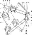
本発明のロボットは、図1に見られるように、それぞれの一端が、ベースプレート(3)に固定されたアクチュエータに回転継手(2)によって連結され、他端が、加工工具(5)が組み付けられる可動プラットフォーム(4)に連結される4つの連鎖(1)を備える。 As shown in FIG. 1, the robot of the present invention has one end connected to an actuator fixed to a base plate (3) by a rotary joint (2) and the other end assembled with a processing tool (5). It comprises four chains (1) connected to the movable platform (4).
連鎖の各々は、2本ずつ平行な4本のバー(6),(6’),(7),(7’)により構成され、ボールジョイント(8)によって互いに連結されている。別の実施の形態では、連鎖は、端に2個のカルダン継手または自在継手を備える単一のバーによって構成される。 Each of the chains is constituted by four parallel bars (6), (6 ′), (7), (7 ′), two by two, and connected to each other by a ball joint (8). In another embodiment, the chain is constituted by a single bar with two cardan joints or universal joints at the ends.
4個のアクチュエータの各々は、これをベースプレート(3)に固定するための固定用支持体(9)、支持体(9)に連結される回転モータ(10)、回転継手(2)を回転させるモータの軸と一体化されたアームにより構成される。別の実施の形態では、同一平面に配置され、同じ方向に配列された4個のリニアモータが使用される。 Each of the four actuators rotates a fixing support (9) for fixing the actuator to the base plate (3), a rotary motor (10) connected to the support (9), and a rotary joint (2). The arm is integrated with the motor shaft. In another embodiment, four linear motors arranged in the same plane and arranged in the same direction are used.
可動プラットフォーム(4)は、回転継手(13)によって互いに連結される4個のアーム部材(11),(11’),(12),(12’)により構成され、可動プラットフォーム(4)を構成するこれらの部材の少なくとも2個は互いに平行で、可動プラットフォームの平面内で1自由度を有する、より詳しくは上記の可動プラットフォーム(4)の平面に垂直な軸に関して1自由度回転が可能な関節式可動プラットフォームを構成する。この回転によって加工工具は−45°から+45°の間で1自由度回転するが、この角度範囲は増幅機構の追加によって拡大でき、これについて以下に説明する。 The movable platform (4) includes four arm members (11), (11 ′), (12), and (12 ′) that are connected to each other by the rotary joint (13), and constitutes the movable platform (4). At least two of these members are parallel to each other and have one degree of freedom in the plane of the movable platform, more particularly a joint capable of one degree of freedom rotation about an axis perpendicular to the plane of the movable platform (4) described above Constitutes a movable platform. This rotation causes the machining tool to rotate one degree of freedom between −45 ° and + 45 °, but this angular range can be expanded by adding an amplification mechanism, which will be described below.
工具(5)は、アーム部材(11),(11’),(12),(12’)のいずれかに一体化される。 The tool (5) is integrated into any one of the arm members (11), (11 ′), (12), and (12 ′).
添付の図面に示される実施の形態において、アーム部材(11),(11’),(12),(12’)のうちの2個のアーム部材(11),(11’)は、その端に横方向の延長部分(14)を有するアームによって構成され、延長部分(14)には内側に穴が設けられ、その穴の中に連鎖(1)のバー(7’)が収納されて回転でき、アーム部材(12),(12’)は、アーム部材(11),(11’)の横方向への延長部分(14)にヒンジ状に連結されたバーによって構成される。 In the embodiment shown in the accompanying drawings, the arm member (11), (11 '), (12), (12' two arm members of a) (11), (11 '), the end Is formed by an arm having a laterally extending portion (14), and the extended portion (14) is provided with a hole inside, and the chain (1) bar (7 ') is accommodated in the hole and rotated. The arm members (12) and (12 ′) are configured by bars that are hingedly connected to the laterally extending portions (14) of the arm members (11) and (11 ′).
図3に示されるように、連鎖(1)のバー(7’)はアクチュエータのモータ(10)の出力軸と同じ空間的な方向付けをされ、アクチュエータはベースプレート(3)の上に対称に配置され、これによって高い剛性、高い位置決め精度、可動範囲全体にわたる均質なパフォーマンスが実現される。 As shown in FIG. 3, the bar (7 ′) of the chain (1) is oriented in the same spatial direction as the output shaft of the motor (10) of the actuator, and the actuator is placed symmetrically on the base plate (3). As a result, high rigidity, high positioning accuracy, and uniform performance over the entire movable range are realized.
アクチュエータ、したがって連鎖のバー(7’)と可動プラットフォーム(4)の延長部分(14)との最良の配置は、図4に示されるように45°、135°、225°、315°であるが、アクチュエータの配置には無限の可能性がある。 The best arrangement of the actuator, and thus the chain bar (7 ') and the extension (14) of the movable platform (4) is 45 °, 135 °, 225 °, 315 ° as shown in FIG. There are endless possibilities for actuator placement.
可動プラットフォームには、工具の回転のための増幅機構を取り付け、回転範囲を広げることができる。可動プラットフォームにこれらのメカニズムを組み付けるには、多くの場合、追加の部品が必要となる。 An amplification mechanism for rotating the tool can be attached to the movable platform to widen the rotation range. Assembling these mechanisms to a movable platform often requires additional components.
回転増幅機構のさまざまな実施例を図5から図9に示し、これらについて以下に説明する。 Various embodiments of the rotary amplification mechanism are shown in FIGS. 5 to 9 and are described below.
図5に示す第一の実施例において、可動プラットフォーム(4)は、回転継手(13)によって連結される4個のアーム部材(11),(11’),(12),(12’)により構成される。4個のアーム部材(11),(11’),(12),(12’)のうちの少なくとも2個は互いに平行である。増幅機構は、その一方のプーリ(15)が部材(11’)の上に組み付けられ、他方のプーリ(16)がアーム部材(11)の上に組み付けられる2個のプーリ(15),(16)と、両方のプーリ(15),(16)の間に配置されたベルト(17)とにより構成される。この実施例において、加工工具はプーリ(16)の軸に連結されている。 In the first embodiment shown in FIG. 5, the movable platform (4) is constituted by four arm members (11), (11 ′), (12), (12 ′) connected by a rotary joint (13). Composed. At least two of the four arm members (11), (11 ′), (12), (12 ′) are parallel to each other. The amplifying mechanism has two pulleys (15), (16) in which one pulley (15) is assembled on the member (11 ') and the other pulley (16) is assembled on the arm member (11). ) And a belt (17) disposed between both pulleys (15), (16). In this embodiment, the processing tool is connected to the shaft of the pulley (16).
図6に示す第二の実施例において、アーム部材(11)はギアリング部(18)を有し、部材(11’)は、ギアリング部(18)とかみ合う歯車(19)を有する。この場合、加工工具(5)はギアリングに連結され、4自由度を有する。 In the second embodiment shown in FIG. 6, the arm member (11) has a gearing portion (18), and the member (11 ′) has a gear (19) that meshes with the gearing portion (18). In this case, the machining tool (5) is connected to the gear ring and has four degrees of freedom.
図7、図8は、可動プラットフォーム(4)が追加の部材、つまりアーム(20)を備える別の実施例を示す。 7 and 8 show another embodiment in which the movable platform (4) is provided with an additional member, the arm (20).
図7の実施例において、可動プラットフォーム(4)は、回転継手によって互いに連結される5個のアーム部材(11),(11’),(12),(12’),(20)により構成される。4個のアーム部材(11)と(11’)および(12)と(12’)とは2個ずつ平行であり、その端で連結されている。5個目の部材(20)は、アーム部材(11),(11’),(12),(12’)のうちの1対の部材(12),(12’)に平行に配置され、その端は他の2個のアーム部材(11),(11’)に連結されている。 In the embodiment of FIG. 7, the movable platform (4) is composed of five arm members (11), (11 ′), (12), (12 ′), (20) that are connected to each other by a rotary joint. The The four arm members (11) and (11 ′) and (12) and (12 ′) are two in parallel and are connected at their ends. The fifth member (20) is arranged in parallel to the pair of members (12), (12 ′) of the arm members (11), (11 ′), (12), (12 ′), The end is connected to the other two arm members (11), (11 ′).
加工部材の回転範囲は、その一方がアーム部材(11),(11’)の一方に組み付けられ、他方が追加部材(20)に組み付けられる2個のプーリ(21),(22)とこれに対応するベルト(23)とによって増幅される。加工工具(5)は、プーリ(22)に組み付けられる。 The rotation range of the processed member includes two pulleys (21) and (22), one of which is assembled to one of the arm members (11) and (11 ') and the other is assembled to the additional member (20). Amplified by the corresponding belt (23). The processing tool (5) is assembled to the pulley (22).
図8において、可動プラットフォーム(4)は、図7の実施例と同じ5個のアーム部材(11),(11’),(12),(12’),(20)により構成され、加工部材の回転範囲は、アーム部材(11),(11’)の一方に設けられたギアリング部(24)と、追加部材(20)に組み付けられた歯車(25)とによって増幅され、加工工具(5)は歯車(25)に組み付けられる。 In FIG. 8, the movable platform (4) is composed of the same five arm members (11), (11 ′), (12), (12 ′), (20) as in the embodiment of FIG. Is rotated by a gearing portion (24) provided on one of the arm members (11) and (11 ′) and a gear (25) assembled to the additional member (20), so that the machining tool ( 5) is assembled to the gear (25).
図9において、可動プラットフォーム(4)は回転継手によって互いに連結される6個のアーム部材(11),(11’),(12),(12’),(20),(26)により構成される。可動プラットフォーム(4)は図7、図8に示されるものと同じ部材により構成されるが、1対のアーム部材(11),(11’)に平行に配置された6個目の部材(26)を備え、6個の部品は3個ずつ平行になる。2個の追加部材(20),(26)は中間点で連結され、ここに加工工具(5)が配置される。回転範囲はギアボックス(28)を使用し、ギアボックス(28)を2個の部品(20),(26)が交差する点に配置することによって増幅される。
In FIG. 9, the movable platform (4) is composed of six arm members (11), (11 ′), (12), (12 ′), (20), (26) connected to each other by a rotary joint. The The movable platform (4) is composed of the same members as those shown in FIGS. 7 and 8, but a sixth member (26) arranged in parallel with the pair of arm members (11) and (11 ′). ), And the six parts are three in parallel. The two additional members (20) and (26) are connected at an intermediate point, and the machining tool (5) is disposed here. The rotation range is amplified by using a gear box (28) and placing the gear box (28) at the point where the two parts (20), (26) intersect.
Claims (15)
前記可動プラットフォームの自由度は、垂直軸に関して−45°から45°での1回転自由度であることを特徴とする4自由度高速パラレルロボット。The 4-degree-of-freedom high-speed parallel robot according to claim 1,
The four-degree-of-freedom high-speed parallel robot characterized in that the degree of freedom of the movable platform is one rotation degree of freedom from -45 ° to 45 ° with respect to the vertical axis.
前記連鎖(1)の各々は、2本ずつ平行で、ボールジョイントによって互いに連結され、前記可動プラットフォーム(4)と前記アクチュエータとに連結される4本のバー(6),(6’),(7),(7’)により構成され、前記可動プラットフォーム(4)に連結される前記バー(7’)は、対応するアクチュエータの回転モータ出力軸の方向と同じ方向に方向付けられていることを特徴とする4自由度高速パラレルロボット。The 4-degree-of-freedom high-speed parallel robot according to claim 1,
Wherein each of the chain (1) is two by two parallel, connected to each other by a ball joint, said movable platform (4) and four bars being connected to said actuator (6), (6 '), ( 7), (7 ′), and the bar (7 ′) connected to the movable platform (4) is oriented in the same direction as the direction of the rotary motor output shaft of the corresponding actuator. A featured 4-DOF high-speed parallel robot.
前記可動プラットフォーム(4)は、前記工具の回転のための増幅機構を含んでいることを特徴とする4自由度高速パラレルロボット。The 4-degree-of-freedom high-speed parallel robot according to claim 1,
The four-degree-of-freedom high-speed parallel robot, wherein the movable platform (4) includes an amplification mechanism for rotating the tool.
前記増幅機構は、2個のプーリ(15),(16)と、ベルト(17)とにより構成され、一方のプーリ(15)は、前記可動プラットフォーム(4)の前記4個のアーム部材(11),(11’),(12),(12’)のうちの1個に組み付けられ、他方のプーリ(16)が前記可動プラットフォームの前記4個のアーム部材(11),(11’),(12),(12’)の別の1個に連結され、前記ベルト(17)は、両方のプーリ(15),(16)の間に配置されるベルト(17)により構成され、前記工具は前記プーリ(16)の軸に組み付けられることを特徴とする4自由度高速パラレルロボット。The 4-degree-of-freedom high-speed parallel robot according to claim 4 ,
The amplifying mechanism includes two pulleys (15) and (16) and a belt (17). One pulley (15) is the four arm members (11) of the movable platform (4). ), (11 ′), (12), (12 ′), and the other pulley (16) is connected to the four arm members (11), (11 ′), The belt (17) is connected to another one of (12) and (12 '), and the belt (17) is constituted by a belt (17) disposed between both pulleys (15) and (16), and the tool Is a four-degree-of-freedom high-speed parallel robot that is assembled to the shaft of the pulley (16).
前記増幅機構は、前記可動プラットフォーム(4)の前記アーム部材(11),(11’),(12),(12’)のうちの1個に設けられたギアリング部(18)と、前記可動プラットフォームの前記アーム部材(11),(11’),(12),(12’)のうちの別の1個に設けられた歯車(19)とにより構成され、前記工具は前記歯車(19)に連結されることを特徴とする4自由度高速パラレルロボット。The 4-degree-of-freedom high-speed parallel robot according to claim 4 ,
The amplification mechanism includes a gearing portion (18) provided in one of the arm members (11), (11 ′), (12), (12 ′) of the movable platform (4), A gear (19) provided on another one of the arm members (11), (11 ′), (12), (12 ′) of the movable platform, and the tool is the gear (19 4 degree-of-freedom high-speed parallel robot.
前記可動プラットフォームはさらに、前記可動プラットフォーム(4)の前記アーム部材(11),(11’),(12),(12’)のうちの2個の間に関節式連結装置によって配置された中間部材(20)を備え、前記工具は前記中間部材(20)に組み付けられることを特徴とする4自由度高速パラレルロボット。The 4-degree-of-freedom high-speed parallel robot according to claim 1,
The movable platform is further intermediate between two of the arm members (11), (11 ′), (12), (12 ′) of the movable platform (4) arranged by an articulated coupling device. A four-degree-of-freedom high-speed parallel robot comprising a member (20), wherein the tool is assembled to the intermediate member (20).
前記可動プラットフォーム(4)を構成する前記アーム部材(11),(11’),(12),(12’)は2個ずつ平行に配置され、前記中間部材(20)は、前記可動プラットフォームを構成するアーム部材のうちの1対のアーム部材(12,12’)に平行に配置され、別の1対のアーム部材(11,11’)にその中央部分で連結されていることを特徴とする4自由度高速パラレルロボット。The 4-degree-of-freedom high-speed parallel robot according to claim 7 ,
The arm members (11), (11 ′), (12), (12 ′) constituting the movable platform (4) are arranged in parallel two by two, and the intermediate member (20) It is arranged in parallel to a pair of arm members (12, 12 ′) of the constituting arm members, and is connected to another pair of arm members (11, 11 ′) at the central portion thereof. A four-degree-of-freedom high-speed parallel robot.
前記工具の回転のための増幅機構を含んでいることを特徴とする4自由度高速パラレルロボット。The 4-degree-of-freedom high-speed parallel robot according to claim 8 ,
A four-degree-of-freedom high-speed parallel robot comprising an amplification mechanism for rotating the tool.
前記増幅機構は、2個のプーリ(21),(22)とベルト(23)とにより構成され、一方のプーリ(21)は、前記可動プラットフォーム(4)の前記4個のアーム部材(11),(11’),(12),(12’)のうちの1個に組み付けられ、他方のプーリ(22)は、前記中間部材(20)に連結され、前記ベルト(23)は、両方のプーリ(21),(22)の間に配置され、前記工具は前記他方のプーリ(22)の軸に組み付けられることを特徴とする4自由度高速パラレルロボット。The 4-degree-of-freedom high-speed parallel robot according to claim 9 ,
The amplification mechanism includes two pulleys (21) and (22) and a belt (23), and one pulley (21) is the four arm members (11) of the movable platform (4). , (11 ′), (12), (12 ′), the other pulley (22) is connected to the intermediate member (20), and the belt (23) A four-degree-of-freedom high-speed parallel robot, which is disposed between pulleys (21) and (22), and wherein the tool is assembled to the shaft of the other pulley (22).
前記増幅機構は、前記可動プラットフォーム(4)の前記アーム部材(11),(11’),(12),(12’)のうちの1個に設けられたギアリング部(24)と前記中間部材(20)に設けられた歯車(25)とにより構成され、前記工具は前記歯車(25)に連結されることを特徴とする4自由度高速パラレルロボット。The 4-degree-of-freedom high-speed parallel robot according to claim 9 ,
The amplification mechanism includes a gearing portion (24) provided in one of the arm members (11), (11 ′), (12), and (12 ′) of the movable platform (4) and the intermediate A four-degree-of-freedom high-speed parallel robot comprising a gear (25) provided on a member (20), wherein the tool is connected to the gear (25).
前記可動プラットフォーム(4)はさらに、前記可動プラットフォーム(4)に関節式連結装置によって連結される2個の中間部材(20),(26)を備えることを特徴とする4自由度高速パラレルロボット。The 4-degree-of-freedom high-speed parallel robot according to claim 1,
The four-degree-of-freedom high-speed parallel robot, wherein the movable platform (4) further includes two intermediate members (20) and (26) connected to the movable platform (4) by an articulated connecting device.
前記可動プラットフォーム(4)を構成する前記アーム部材(11)(11´)(12)(12´)及び前記中間部材(20)(26)は、互いに平行に配置される3個の前記アーム部材(11)(11´)及び前記中間部材(26)と、互いに平行に配置される残りの3個の前記アーム部材(12)(12´)及び前記中間部材(20)とにより構成され、
前記中間部材(20),(26)の第一の中間部材(20)は、前記可動プラットフォーム(4)を構成するアーム部材(11)(11´)(12)(12´)のうちの第一の対のアーム部材(12,12’)に平行に組み付けられ、前記第一の中間部材(20)は、前記アーム部材(11),(11’),(12),(12’)のうちの2個の第二の対のアーム部材(11,11’)に中央部で連結され、前記第二の中間部材(26)は前記可動プラットフォーム(4)の第二の対のアーム部材(11,11’)に平行に組み付けられ、前記第一の対のアーム部材(12,12’)にその中央部で連結され、前記2個の中間部材(20),(26)は位置(27)で互いに連結され、この位置(27)に前記工具が配置されることを特徴とする4自由度高速パラレルロボット。The 4-degree-of-freedom high-speed parallel robot according to claim 12 ,
The arm members (11) (11 ′) (12) (12 ′) and the intermediate members (20) (26) constituting the movable platform (4) are three arm members arranged in parallel to each other. (11) (11 ') and the intermediate member (26), and the remaining three arm members (12) (12') and the intermediate member (20) arranged in parallel to each other,
The first intermediate member (20) of the intermediate members (20), (26) is the first of the arm members (11) (11 ') (12) (12') constituting the movable platform (4) . The first intermediate member (20) is assembled in parallel to a pair of arm members (12, 12 '), and the first intermediate member (20) is formed of the arm members (11), (11'), (12), (12 '). the two second pair of arm members of the inner (11, 11 ') are connected by a central portion, said second intermediate member (26) the arm member of the second pair of said movable platform (4) ( 11 and 11 ') and is connected to the first pair of arm members (12 and 12') at the center thereof, and the two intermediate members (20) and (26) are positioned at the position (27 ), And the tool is arranged at this position (27). High-speed parallel robot.
前記可動プラットフォームは、前記工具の回転のための増幅要素を備えることを特徴とする4自由度高速パラレルロボット。The 4-degree-of-freedom high-speed parallel robot according to claim 13 ,
The four-degree-of-freedom high-speed parallel robot, wherein the movable platform includes an amplification element for rotating the tool.
前記増幅要素は、前記中間部材(20),(26)の前記連結の位置(27)に組み付けられたギアボックス(28)を備えることを特徴とする4自由度高速パラレルロボット。The 4-degree-of-freedom high-speed parallel robot according to claim 14 ,
The four-degree-of-freedom high-speed parallel robot, wherein the amplifying element includes a gear box (28) assembled at the connecting position (27) of the intermediate members (20), (26).
Applications Claiming Priority (3)
| Application Number | Priority Date | Filing Date | Title |
|---|---|---|---|
| ESP200500357 | 2005-02-17 | ||
| ES200500357A ES2258917B1 (en) | 2005-02-17 | 2005-02-17 | PARALLEL ROBOT WITH FOUR DEGREES OF HIGH SPEED FREEDOM. |
| PCT/ES2006/000053 WO2006087399A1 (en) | 2005-02-17 | 2006-02-08 | High-speed parallel robot with four degrees of freedom |
Publications (3)
| Publication Number | Publication Date |
|---|---|
| JP2008529816A JP2008529816A (en) | 2008-08-07 |
| JP2008529816A5 JP2008529816A5 (en) | 2009-03-26 |
| JP5160902B2 true JP5160902B2 (en) | 2013-03-13 |
Family
ID=36916163
Family Applications (1)
| Application Number | Title | Priority Date | Filing Date |
|---|---|---|---|
| JP2007555647A Expired - Fee Related JP5160902B2 (en) | 2005-02-17 | 2006-02-08 | 4-degree-of-freedom high-speed parallel robot |
Country Status (21)
| Country | Link |
|---|---|
| US (1) | US7735390B2 (en) |
| EP (2) | EP2283983A1 (en) |
| JP (1) | JP5160902B2 (en) |
| KR (2) | KR20090097196A (en) |
| AT (1) | ATE484365T1 (en) |
| AU (1) | AU2006215525B2 (en) |
| BR (1) | BRPI0607143B1 (en) |
| CA (1) | CA2598420C (en) |
| CY (1) | CY1111239T1 (en) |
| DE (1) | DE602006017528D1 (en) |
| DK (1) | DK1870214T3 (en) |
| ES (2) | ES2258917B1 (en) |
| MA (1) | MA29252B1 (en) |
| NZ (1) | NZ565070A (en) |
| PL (1) | PL1870214T3 (en) |
| PT (1) | PT1870214E (en) |
| RU (1) | RU2400351C2 (en) |
| SI (1) | SI1870214T1 (en) |
| TN (1) | TNSN07315A1 (en) |
| WO (1) | WO2006087399A1 (en) |
| ZA (1) | ZA200706914B (en) |
Families Citing this family (125)
| Publication number | Priority date | Publication date | Assignee | Title |
|---|---|---|---|---|
| ES2333930B1 (en) * | 2007-10-24 | 2010-12-28 | Universidad Del Pais Vasco Euskal Herriko Unibertsitatea | PARALLEL ROBOT WITH FOUR DEGREES OF FREEDOM. |
| CA2712260A1 (en) | 2008-01-18 | 2009-07-23 | Centre National De La Recherche Scientifique (Cnrs) | Two degree-of-freedom parallel manipulator |
| JP4420959B2 (en) * | 2008-04-10 | 2010-02-24 | 村田機械株式会社 | Parallel mechanism |
| JP5126892B2 (en) * | 2008-12-19 | 2013-01-23 | 国立大学法人 名古屋工業大学 | Multi-degree-of-freedom force-sensing manipulator |
| CA2693728A1 (en) * | 2009-02-20 | 2010-08-20 | Philip A. Hill | Goniometric positioning system |
| US8877648B2 (en) * | 2009-03-26 | 2014-11-04 | Semprius, Inc. | Methods of forming printable integrated circuit devices by selective etching to suspend the devices from a handling substrate and devices formed thereby |
| DE102009017907A1 (en) * | 2009-04-17 | 2010-10-21 | Weber Maschinenbau Gmbh Breidenbach | Robot with delta kinematics |
| FR2952573B1 (en) | 2009-10-02 | 2011-12-09 | Commissariat Energie Atomique | STRUCTURE OF ROBOT OR HAPTIC INTERFACE WITH PARALLEL ARM |
| CN101708611B (en) * | 2009-11-09 | 2011-07-27 | 天津大学 | Parallel mechanism with three-dimensional translation and one-dimensional rotation |
| CN102107431A (en) * | 2009-12-29 | 2011-06-29 | 鸿富锦精密工业(深圳)有限公司 | Parallel robot |
| NL2004167C2 (en) | 2010-01-28 | 2011-07-29 | Univ Delft Tech | Robot with multiple degrees of freedom. |
| DE102010009447A1 (en) * | 2010-02-24 | 2011-08-25 | Fraunhofer-Gesellschaft zur Förderung der angewandten Forschung e.V., 80686 | joint |
| CN101863024B (en) * | 2010-06-29 | 2011-11-09 | 天津大学 | Three-dimensional translation and one-dimensional rotation parallel mechanism capable of realizing high-speed movement |
| JP5403303B2 (en) * | 2010-08-02 | 2014-01-29 | 株式会社安川電機 | Parallel mechanism |
| WO2012031635A1 (en) * | 2010-09-10 | 2012-03-15 | Abb Research Ltd. | Industrial robot |
| CN102407524A (en) * | 2010-09-21 | 2012-04-11 | 鸿富锦精密工业(深圳)有限公司 | Robot |
| CN102441889A (en) * | 2010-09-30 | 2012-05-09 | 鸿富锦精密工业(深圳)有限公司 | Parallel-connection robot |
| CN201907121U (en) * | 2010-12-29 | 2011-07-27 | 天津大学 | Three-dimensional translational and one-dimensional rotational parallel mechanism |
| CN102152317B (en) * | 2011-03-29 | 2012-06-06 | 天津大学 | Accurate straight-line motion mechanism only including revolute pair |
| CN102179819B (en) * | 2011-04-14 | 2013-05-15 | 天津大学 | Spatial accurate straight-line motion mechanism |
| CN102229141B (en) * | 2011-04-27 | 2013-08-28 | 天津大学 | Parallel mechanism capable of realizing four-degree-of-freedom movement |
| CN102161200B (en) * | 2011-04-27 | 2012-05-16 | 天津大学 | Parallel dislocation type parallel mechanism capable of three-dimensional translational motion and one-dimensional rotation |
| CN102152306B (en) * | 2011-04-27 | 2012-05-23 | 天津大学 | Bar-wheel combined type three-translation one-rotation parallel mechanism |
| CN102161201B (en) * | 2011-04-27 | 2012-05-16 | 天津大学 | Up-and-down telescopic three-platform one-rotation parallel mechanism |
| CN102259269A (en) * | 2011-07-08 | 2011-11-30 | 常州大学 | Three-dimensional rotary spherical parallel mechanism |
| FR2978933B1 (en) * | 2011-08-12 | 2013-09-06 | Fatronik France | METHOD FOR CONTROLLING A REDUNDANT PARALLEL ACTUATING AUTOMATE, ASSOCIATED CONTROL DEVICE AND AUTOMATE. |
| US8931359B2 (en) | 2011-09-19 | 2015-01-13 | Vivero One Research, Llc | Parallelogram based actuating device |
| US8464603B2 (en) * | 2011-09-19 | 2013-06-18 | Vivero One Research, Llc | Parallelogram based actuating device |
| CN102490187B (en) * | 2011-12-13 | 2013-12-25 | 天津大学 | Parallel manipulator with five freedom degrees |
| CN102490186B (en) * | 2011-12-13 | 2013-12-18 | 天津大学 | Four-degree-of-freedom parallel manipulator |
| CN102490185B (en) * | 2011-12-13 | 2014-05-21 | 天津大学 | Face-symmetry five-freedom-degree parallel-connection manipulator |
| CN102514004B (en) * | 2011-12-19 | 2014-09-24 | 天津大学 | Translational high-speed parallel mechanism with four branched chains and two degrees of freedom |
| CN102513996A (en) * | 2011-12-19 | 2012-06-27 | 天津大学 | Double-parallelism type parallel mechanism with three-dimensional translation and one-dimensional rotation functions |
| CN102554916A (en) * | 2012-01-10 | 2012-07-11 | 天津大学 | Two-degrees-of-freedom translation over restraint parallel mechanism |
| CN102554918A (en) * | 2012-01-10 | 2012-07-11 | 天津大学 | Over-constraint parallel mechanism with three degrees of freedom |
| CN102554917A (en) * | 2012-01-10 | 2012-07-11 | 天津大学 | Multi-over restraint parallel mechanism with two-dimensional translation and one-dimensional rotation |
| NL2010124C2 (en) * | 2012-01-13 | 2013-10-29 | Penta Robotics Patents B V | Fast pick-and-place parallel robot with compact travelling plate. |
| CN102632499B (en) * | 2012-03-27 | 2014-07-02 | 西安交通大学 | Operating mechanism used in Par4 parallel robot |
| CN102601797B (en) * | 2012-04-07 | 2014-08-06 | 大连创奇科技有限公司 | Three-dimensional-translation and one-dimensional-rotation high-speed parallel robot |
| CN102626922B (en) * | 2012-04-12 | 2015-01-14 | 天津大学 | Four-branch-chain two-dimensional translation and one-dimensional rotation freedom parallel mechanical arm |
| CN102848385A (en) * | 2012-04-12 | 2013-01-02 | 天津大学 | High-speed parallel manipulator with two-dimensional translation and one-dimensional rotation freedom degrees |
| CN102848381B (en) * | 2012-04-12 | 2014-12-17 | 天津大学 | High-speed parallel mechanism with two-dimensional translation and one-dimensional rotation of four branch chains |
| CN102632501A (en) * | 2012-04-12 | 2012-08-15 | 天津大学 | Two-dimensional translation and one-dimensional rotation high-speed parallel manipulator |
| CN102848382B (en) * | 2012-04-12 | 2015-01-14 | 天津大学 | High-speed parallel manipulator with three-dimensional translation and one-dimensional rotation |
| CN102642205A (en) * | 2012-04-20 | 2012-08-22 | 清华大学 | Parallel mechanism of four-degree-of-freedom dual acting platform |
| CN102692201B (en) * | 2012-06-19 | 2014-07-02 | 重庆大学 | Device for measuring spatial motion with six degrees of freedom and dynamic measuring method |
| JP6110620B2 (en) * | 2012-09-26 | 2017-04-05 | キヤノン電子株式会社 | Parallel link robot |
| CN103707281A (en) * | 2012-09-29 | 2014-04-09 | 南昌大学 | Spatial four-degree-of-freedom parallel mechanism capable of three-dimensional translation and one-dimensional rotation |
| CN102922511A (en) * | 2012-11-02 | 2013-02-13 | 清华大学 | Three-move one-rotation four-freedom degree space parallel connection mechanism |
| CZ2012799A3 (en) * | 2012-11-16 | 2014-08-27 | ÄŚVUT v Praze, Fakulta strojnĂ | Redundant Delta manipulator |
| KR101382666B1 (en) * | 2012-11-26 | 2014-04-07 | 양국진 | Parallel manipulator |
| CN102990674B (en) * | 2012-12-04 | 2015-01-14 | 天津大学 | A/B shaft parallel mechanism |
| CN102975197A (en) * | 2012-12-04 | 2013-03-20 | 天津大学 | Parallel manipulator with three-dimensional translation and two-dimensional rotation degree of freedom |
| CN102975202B (en) * | 2012-12-04 | 2014-11-05 | 天津大学 | Five-degree-of-freedom parallel manipulator capable of realizing high-velocity motion |
| CN103009376B (en) * | 2012-12-04 | 2015-01-14 | 天津大学 | Spatial three-dimensional rotation parallel mechanism |
| KR101407228B1 (en) * | 2012-12-05 | 2014-06-13 | 양국진 | Multi-parallel manipulator system |
| EP2740563B1 (en) | 2012-12-05 | 2018-04-04 | TRUMPF Werkzeugmaschinen GmbH & Co. KG | Processing device, processing machine and method for moving a machining head |
| TWI483820B (en) * | 2012-12-21 | 2015-05-11 | Hiwin Tech Corp | Parallel joint structure of the robot |
| CN103072133B (en) * | 2013-01-14 | 2016-01-06 | 燕山大学 | A kind of Three Degree Of Freedom moved decoupling parallel robot mechanism |
| KR101411095B1 (en) | 2013-02-28 | 2014-06-25 | 고려대학교 산학협력단 | Four degree of freedom mechanism apparatus |
| JP5682642B2 (en) * | 2013-03-05 | 2015-03-11 | 株式会社安川電機 | Parallel link robot |
| US11353084B2 (en) * | 2013-03-15 | 2022-06-07 | Clearmotion Acquisition I Llc | Rotary actuator driven vibration isolation |
| US9475077B2 (en) | 2013-03-28 | 2016-10-25 | Specialty Coating Systems, Inc. | High speed coating and dispensing apparatus |
| CN103231371B (en) * | 2013-04-23 | 2015-10-14 | 广州中国科学院先进技术研究所 | Parallel robot and parallelogram levers group thereof |
| US9198813B2 (en) * | 2013-05-18 | 2015-12-01 | Yuan Ze University | Movement device having a stewart platform |
| CN103448059B (en) * | 2013-08-19 | 2015-11-18 | 燕山大学 | Containing planar six-rod closed loop side chain 6DOF parallel institution |
| CN103465255B (en) * | 2013-09-24 | 2015-08-26 | 北京交通大学 | A kind of hydraulic drive parallel mobile robot |
| CH708909B1 (en) * | 2013-11-29 | 2024-01-15 | Steiner Ag Weggis | Method and device for discharging milk foam or liquids. |
| CN103753521B (en) * | 2014-01-17 | 2016-06-29 | 天津大学 | A kind of pinion and-rack four-degree-of-freedom high speed parallel robot |
| CN103846910A (en) * | 2014-02-28 | 2014-06-11 | 天津大学 | Four-freedom high-speed parallel connection mechanical hand |
| CN103846908B (en) * | 2014-02-28 | 2015-10-21 | 天津大学 | The flat one turn of high-speed parallel manipulator of four side chains three |
| US9868205B2 (en) * | 2014-03-18 | 2018-01-16 | Abb Schweiz Ag | Compact parallel kinematics robot |
| CN104002302B (en) * | 2014-05-07 | 2015-09-16 | 燕山大学 | A kind of have virtual axle two, Three Degree Of Freedom tilter |
| FR3020977B1 (en) * | 2014-05-19 | 2017-07-28 | Univ Montpellier 2 Sciences Et Techniques | NACELLE FOR PARALLEL ROBOT FOR ACTING ON AN OBJECT |
| JP2016036863A (en) * | 2014-08-06 | 2016-03-22 | ソニー株式会社 | Parallel link robot and parallel link structure |
| CN104260079A (en) * | 2014-09-16 | 2015-01-07 | 天津市天大银泰科技有限公司 | Parallel robot device comprising double-space parallel branch chains for 3D (three-dimensional) printer |
| NL2013948B1 (en) * | 2014-12-10 | 2016-10-11 | Univ Delft Tech | Robot with multiple degrees of freedom. |
| CN104589326B (en) * | 2015-01-24 | 2016-02-24 | 江西省机械科学研究所 | Band drives the flat one turn of space four-degree-of-freedom manipulator of electric cylinder three |
| DE102016000189A1 (en) | 2015-03-06 | 2016-09-29 | Sew-Eurodrive Gmbh & Co Kg | Transport device with structure-forming, in particular housing-forming, linear drives, and method for transporting a load |
| US9214314B1 (en) * | 2015-03-10 | 2015-12-15 | Varian Semiconductor Equipment Associates, Inc. | Ion beam manipulator |
| CN104802154B (en) * | 2015-03-23 | 2016-08-24 | 杭州娃哈哈集团有限公司 | A kind of four-degree-of-freedom high-speed parallel manipulator |
| CN104942800B (en) * | 2015-07-02 | 2017-03-22 | 上海交通大学 | Three-translation one-rotation four-freedom rotation and translation complete decoupling parallel mechanism |
| CN105127979A (en) * | 2015-09-08 | 2015-12-09 | 常州大学 | Three-horizontal movement one-rotation parallel robot mechanism |
| CN105234929B (en) * | 2015-11-16 | 2017-08-29 | 南京理工大学 | A kind of three flat one turn of four-freedom parallel mechanism |
| CN105234927B (en) * | 2015-11-16 | 2017-03-29 | 南京理工大学 | A kind of three side chain four-degree-of-freedom holohedral symmetry parallel institutions |
| CN105291095B (en) * | 2015-11-27 | 2017-05-10 | 中国地质大学(武汉) | Six-freedom-degree heavy-load leveling robot mechanism |
| CN105291096B (en) * | 2015-11-27 | 2017-02-01 | 中国地质大学(武汉) | Heavy-load horizontal-movement transfer robot mechanism with three degrees of freedom |
| CN105437213B (en) * | 2015-12-17 | 2017-05-10 | 天津大学 | Multi-closed-ring dual-rotary catching and releasing mechanism taking spatial four-bar mechanism as platform |
| CN106994642B (en) * | 2016-01-22 | 2019-11-22 | 香港理工大学 | Mixed connection burnishing machine |
| CN105522566B (en) * | 2016-01-28 | 2017-12-15 | 东莞理工学院 | A kind of accurate M type four-degree-of-freedom parallel connection positioners |
| CN105643603B (en) * | 2016-03-12 | 2017-09-08 | 常州大学 | A kind of three one rotating parallel device people manipulators of translation of the kinematic pair moving platform of weak coupling three |
| CN105619387B (en) * | 2016-03-12 | 2017-09-08 | 常州大学 | A kind of single input three translates rotating parallel device people's device |
| CN105619384B (en) * | 2016-03-12 | 2017-09-08 | 常州大学 | A kind of single input three translates a rotating parallel device people manipulator |
| CN105666465B (en) * | 2016-03-12 | 2017-09-08 | 常州大学 | A kind of three one rotating parallel device people manipulators of translation of the kinematic pair moving platform of weak coupling two |
| US10767675B2 (en) * | 2016-05-02 | 2020-09-08 | Flexsys, Inc. | Deployable compliant mechanism |
| CN105856192B (en) * | 2016-05-10 | 2018-04-03 | 燕山大学 | In the presence of four side chain two degrees of freedom one-rotation parallel mechanisms of two continuous pivot centers |
| CN105945917B (en) * | 2016-06-02 | 2020-07-28 | 燕山大学 | Multi-rotation center type two-rotation one-movement parallel mechanism |
| CN105904441B (en) * | 2016-06-07 | 2017-11-17 | 浙江理工大学 | The movement of one kind two two rotates four-degree-of-freedom holohedral symmetry parallel institution |
| NL2017167B1 (en) * | 2016-07-14 | 2018-01-18 | Penta Robotics Patents B V | Robot arm |
| CN107756217A (en) * | 2016-08-22 | 2018-03-06 | 香港理工大学 | A kind of vertical connection in series-parallel burnishing machine |
| CN106217356A (en) * | 2016-08-25 | 2016-12-14 | 芜湖瑞思机器人有限公司 | A kind of four-shaft parallel robot train formula moving platform |
| FR3057191B1 (en) | 2016-10-06 | 2018-11-02 | Universite De Franche-Comte | ROBOTIC STRUCTURE WITH SIX DEGREES OF FREEDOM FOR PREHENSION |
| CN106378771B (en) * | 2016-11-21 | 2018-10-02 | 南京理工大学 | A kind of multi-coordinate high speed parallel robot mechanism |
| CN106426115B (en) * | 2016-11-24 | 2019-03-19 | 天津大学 | The flat one turn of high-speed parallel manipulator of four branch of rocking bar dislocation type three |
| CN106426114B (en) * | 2016-11-24 | 2019-03-19 | 天津大学 | The flat one turn of high-speed parallel manipulator of four branch of cross slider type three |
| CN107225559B (en) * | 2017-05-25 | 2019-07-26 | 清华大学 | A kind of four-degree-of-freedom high speed parallel robot of achievable SCARA movement |
| CN106976070B (en) * | 2017-05-25 | 2019-06-18 | 清华大学 | A kind of high speed shunting means of achievable three-dimensional translating and one-dimensional rotation |
| CN107139162B (en) * | 2017-06-12 | 2019-11-22 | 清华大学 | Sorting machine people in parallel with double acting platform structure |
| CN107127741B (en) * | 2017-07-10 | 2023-06-09 | 勃肯特(余姚)机器人技术有限公司 | Four-axis parallel movable disc and four-axis parallel robot |
| CN107617890B (en) * | 2017-10-18 | 2019-11-19 | 北京交通大学 | It is a kind of with the redundantly driven parallel bed executing agency for evading Strange properties |
| CN107803821A (en) * | 2017-11-23 | 2018-03-16 | 南京理工大学 | A kind of high speed parallel robot mechanism with two kinds of operator schemes |
| CN107953316A (en) * | 2017-12-29 | 2018-04-24 | 勃肯特(天津)机器人技术有限公司 | Slidingtype movable disk and four-shaft parallel robot |
| CN108858139B (en) * | 2018-06-27 | 2021-04-30 | 大连理工大学 | High-speed parallel mechanism with reconfigurable characteristic for multi-motion platform |
| CN109107880B (en) * | 2018-08-31 | 2023-09-26 | 昆明理工大学 | Four-degree-of-freedom parallel mechanism for vibrating screen |
| CN109531543B (en) * | 2018-12-21 | 2022-08-30 | 清华大学 | Four-freedom parallel robot with double-acting platform structure |
| CN109531556B (en) * | 2018-12-26 | 2021-09-24 | 清华大学 | Four-freedom-degree cylindrical coordinate parallel robot |
| JP1646432S (en) * | 2019-02-15 | 2019-11-25 | ||
| CN110695962A (en) * | 2019-09-03 | 2020-01-17 | 南京理工大学 | Four-degree-of-freedom parallel robot mechanism |
| CN110576428B (en) * | 2019-09-29 | 2021-09-21 | 清华大学 | Over-constrained four-degree-of-freedom high-speed parallel robot |
| CN110806200B (en) * | 2019-10-09 | 2021-08-17 | 陈立坡 | Laser positioning auxiliary platform |
| CN111267078B (en) * | 2020-04-02 | 2021-09-07 | 燕山大学 | Independently-controlled two-rotation one-shift redundant drive parallel mechanism |
| WO2023192681A1 (en) * | 2022-04-01 | 2023-10-05 | Vanderbilt University | Inertia-based improvements to robots and robotic systems |
| CN114918902B (en) * | 2022-05-19 | 2023-09-26 | 南京理工大学 | Three-dimensional-to-one four-degree-of-freedom parallel mechanism |
| CN114918903B (en) * | 2022-05-19 | 2024-03-19 | 南京理工大学 | Three-plane two-to-five-degree-of-freedom parallel mechanism |
| WO2024062507A1 (en) * | 2022-09-19 | 2024-03-28 | I.M.A. Industria Macchine Automatiche S.P.A. | Robotic manipulation apparatus for objects |
Family Cites Families (21)
| Publication number | Priority date | Publication date | Assignee | Title |
|---|---|---|---|---|
| US3250996A (en) * | 1964-12-14 | 1966-05-10 | Electro Mechanical Instr Co | Extended scale electrical meter with motion multiplying flexible coupling |
| US4435116A (en) | 1982-05-27 | 1984-03-06 | Deberg Walter H | Robotic manipulator |
| EP0127895B1 (en) * | 1983-06-02 | 1990-03-21 | Sumitomo Electric Industries Limited | Positioning mechanism |
| CH672089A5 (en) * | 1985-12-16 | 1989-10-31 | Sogeva Sa | |
| JP3365802B2 (en) * | 1992-12-01 | 2003-01-14 | 健 柳沢 | Walking robot |
| JP3640087B2 (en) * | 1994-11-29 | 2005-04-20 | 豊田工機株式会社 | Machine Tools |
| US5847528A (en) * | 1995-05-19 | 1998-12-08 | Canadian Space Agency | Mechanism for control of position and orientation in three dimensions |
| SE513334C2 (en) * | 1997-09-12 | 2000-08-28 | Abb Ab | Apparatus for relative movement of two elements |
| US6464448B1 (en) * | 1998-09-01 | 2002-10-15 | Brooks Automation, Inc. | Substrate transport apparatus |
| JP3553806B2 (en) | 1998-10-19 | 2004-08-11 | オークマ株式会社 | Parallel mechanism machine tool |
| US6324934B1 (en) * | 1999-03-01 | 2001-12-04 | Creative Design Corporation | Robot arm |
| US7337691B2 (en) * | 1999-08-05 | 2008-03-04 | Shambhu Nath Roy | Parallel kinematics mechanism with a concentric spherical joint |
| JP3806273B2 (en) * | 1999-09-17 | 2006-08-09 | 株式会社ジェイテクト | 4-DOF parallel robot |
| SE0000420L (en) * | 2000-02-10 | 2001-04-02 | Abb Ab | Industrial robot according to the delta concept, procedure and use of such robot |
| EP1930133B1 (en) * | 2000-03-01 | 2014-04-09 | Robert Bosch GmbH | Robot for handling products in a three-dimensional space |
| SE517356C2 (en) | 2000-09-11 | 2002-05-28 | Abb Ab | Manipulator comprising at least three arms for moving a body in space |
| SE0100134D0 (en) * | 2001-01-15 | 2001-01-15 | Abb Ab | Industrial robot |
| SE524747C2 (en) * | 2002-02-06 | 2004-09-28 | Abb Ab | Industrial robot containing a parallel kinematic manipulator for moving an object in space |
| SE0201848D0 (en) * | 2002-06-14 | 2002-06-14 | Abb Ab | Device for industrial robot |
| JP3931296B2 (en) * | 2003-03-27 | 2007-06-13 | 株式会社ジェイテクト | 4-DOF parallel robot |
| JP4120501B2 (en) * | 2003-07-08 | 2008-07-16 | 株式会社ジェイテクト | 4-DOF parallel robot and parallel link machine |
-
2005
- 2005-02-17 ES ES200500357A patent/ES2258917B1/en not_active Expired - Fee Related
-
2006
- 2006-02-08 AT AT06708871T patent/ATE484365T1/en active
- 2006-02-08 AU AU2006215525A patent/AU2006215525B2/en not_active Ceased
- 2006-02-08 SI SI200630890T patent/SI1870214T1/en unknown
- 2006-02-08 EP EP10183711A patent/EP2283983A1/en not_active Withdrawn
- 2006-02-08 KR KR1020097015083A patent/KR20090097196A/en active IP Right Grant
- 2006-02-08 PT PT06708871T patent/PT1870214E/en unknown
- 2006-02-08 EP EP06708871A patent/EP1870214B1/en active Active
- 2006-02-08 CA CA2598420A patent/CA2598420C/en not_active Expired - Fee Related
- 2006-02-08 DE DE602006017528T patent/DE602006017528D1/en active Active
- 2006-02-08 BR BRPI0607143A patent/BRPI0607143B1/en not_active IP Right Cessation
- 2006-02-08 DK DK06708871.6T patent/DK1870214T3/en active
- 2006-02-08 KR KR1020077018769A patent/KR101023671B1/en active IP Right Grant
- 2006-02-08 PL PL06708871T patent/PL1870214T3/en unknown
- 2006-02-08 WO PCT/ES2006/000053 patent/WO2006087399A1/en active Application Filing
- 2006-02-08 ZA ZA200706914A patent/ZA200706914B/en unknown
- 2006-02-08 NZ NZ565070A patent/NZ565070A/en not_active IP Right Cessation
- 2006-02-08 ES ES06708871T patent/ES2354566T3/en active Active
- 2006-02-08 RU RU2007134395/02A patent/RU2400351C2/en not_active IP Right Cessation
- 2006-02-08 JP JP2007555647A patent/JP5160902B2/en not_active Expired - Fee Related
- 2006-02-08 US US11/816,572 patent/US7735390B2/en not_active Expired - Fee Related
-
2007
- 2007-08-16 MA MA30142A patent/MA29252B1/en unknown
- 2007-08-17 TN TNP2007000315A patent/TNSN07315A1/en unknown
-
2011
- 2011-01-03 CY CY20111100003T patent/CY1111239T1/en unknown
Also Published As
| Publication number | Publication date |
|---|---|
| US7735390B2 (en) | 2010-06-15 |
| CA2598420C (en) | 2010-11-30 |
| EP1870214B1 (en) | 2010-10-13 |
| EP1870214A1 (en) | 2007-12-26 |
| ZA200706914B (en) | 2008-11-26 |
| KR101023671B1 (en) | 2011-03-25 |
| PT1870214E (en) | 2011-01-18 |
| MA29252B1 (en) | 2008-02-01 |
| BRPI0607143A2 (en) | 2009-08-11 |
| EP2283983A1 (en) | 2011-02-16 |
| AU2006215525B2 (en) | 2011-02-10 |
| BRPI0607143B1 (en) | 2018-09-25 |
| PL1870214T3 (en) | 2011-10-31 |
| DK1870214T3 (en) | 2011-02-07 |
| KR20070108522A (en) | 2007-11-12 |
| JP2008529816A (en) | 2008-08-07 |
| DE602006017528D1 (en) | 2010-11-25 |
| CA2598420A1 (en) | 2006-08-24 |
| WO2006087399A1 (en) | 2006-08-24 |
| ES2258917A1 (en) | 2006-09-01 |
| SI1870214T1 (en) | 2011-03-31 |
| RU2007134395A (en) | 2009-03-27 |
| ATE484365T1 (en) | 2010-10-15 |
| CY1111239T1 (en) | 2015-06-11 |
| NZ565070A (en) | 2010-03-26 |
| RU2400351C2 (en) | 2010-09-27 |
| TNSN07315A1 (en) | 2008-12-31 |
| ES2258917B1 (en) | 2007-12-01 |
| KR20090097196A (en) | 2009-09-15 |
| US20090019960A1 (en) | 2009-01-22 |
| ES2354566T3 (en) | 2011-03-16 |
| AU2006215525A1 (en) | 2006-08-24 |
Similar Documents
| Publication | Publication Date | Title |
|---|---|---|
| JP5160902B2 (en) | 4-degree-of-freedom high-speed parallel robot | |
| KR100705143B1 (en) | Horizontal articulated robot | |
| JP5403303B2 (en) | Parallel mechanism | |
| KR100710968B1 (en) | Link drive mechanism and industrial robot using the same | |
| US20090266194A1 (en) | Robotic arm driving mechanism | |
| JP2008529816A5 (en) | ||
| TWI765135B (en) | An industrial robot arm | |
| JP2003535711A (en) | Control arm with two parallel branches | |
| KR102612120B1 (en) | Planar articulated robot arm system | |
| KR20080036133A (en) | Device for swiveling objects | |
| JP5463174B2 (en) | Joint device and substrate transfer device | |
| US20230010862A1 (en) | An agile robot arm for positioning a tool with controlled orientation | |
| JPH03196980A (en) | Articulated 6 degree-of-freedom robot mechanism, and assembling and working unit with that mechanism | |
| JPS63306888A (en) | Multi-joint type robot |
Legal Events
| Date | Code | Title | Description |
|---|---|---|---|
| A521 | Request for written amendment filed |
Free format text: JAPANESE INTERMEDIATE CODE: A523 Effective date: 20090206 |
|
| A621 | Written request for application examination |
Free format text: JAPANESE INTERMEDIATE CODE: A621 Effective date: 20090206 |
|
| A131 | Notification of reasons for refusal |
Free format text: JAPANESE INTERMEDIATE CODE: A131 Effective date: 20110802 |
|
| A521 | Request for written amendment filed |
Free format text: JAPANESE INTERMEDIATE CODE: A523 Effective date: 20111102 |
|
| A02 | Decision of refusal |
Free format text: JAPANESE INTERMEDIATE CODE: A02 Effective date: 20111220 |
|
| A521 | Request for written amendment filed |
Free format text: JAPANESE INTERMEDIATE CODE: A523 Effective date: 20120420 |
|
| A911 | Transfer to examiner for re-examination before appeal (zenchi) |
Free format text: JAPANESE INTERMEDIATE CODE: A911 Effective date: 20120502 |
|
| A131 | Notification of reasons for refusal |
Free format text: JAPANESE INTERMEDIATE CODE: A131 Effective date: 20121002 |
|
| A521 | Request for written amendment filed |
Free format text: JAPANESE INTERMEDIATE CODE: A523 Effective date: 20121005 |
|
| TRDD | Decision of grant or rejection written | ||
| A01 | Written decision to grant a patent or to grant a registration (utility model) |
Free format text: JAPANESE INTERMEDIATE CODE: A01 Effective date: 20121113 |
|
| A61 | First payment of annual fees (during grant procedure) |
Free format text: JAPANESE INTERMEDIATE CODE: A61 Effective date: 20121213 |
|
| R150 | Certificate of patent or registration of utility model |
Ref document number: 5160902 Country of ref document: JP Free format text: JAPANESE INTERMEDIATE CODE: R150 Free format text: JAPANESE INTERMEDIATE CODE: R150 |
|
| FPAY | Renewal fee payment (event date is renewal date of database) |
Free format text: PAYMENT UNTIL: 20151221 Year of fee payment: 3 |
|
| R250 | Receipt of annual fees |
Free format text: JAPANESE INTERMEDIATE CODE: R250 |
|
| R250 | Receipt of annual fees |
Free format text: JAPANESE INTERMEDIATE CODE: R250 |
|
| R250 | Receipt of annual fees |
Free format text: JAPANESE INTERMEDIATE CODE: R250 |
|
| R250 | Receipt of annual fees |
Free format text: JAPANESE INTERMEDIATE CODE: R250 |
|
| R250 | Receipt of annual fees |
Free format text: JAPANESE INTERMEDIATE CODE: R250 |
|
| LAPS | Cancellation because of no payment of annual fees |