JP5160778B2 - Motor assembly with multi-functional components - Google Patents
Motor assembly with multi-functional components Download PDFInfo
- Publication number
- JP5160778B2 JP5160778B2 JP2006343768A JP2006343768A JP5160778B2 JP 5160778 B2 JP5160778 B2 JP 5160778B2 JP 2006343768 A JP2006343768 A JP 2006343768A JP 2006343768 A JP2006343768 A JP 2006343768A JP 5160778 B2 JP5160778 B2 JP 5160778B2
- Authority
- JP
- Japan
- Prior art keywords
- spindle
- hub
- motor assembly
- cup
- end portion
- Prior art date
- Legal status (The legal status is an assumption and is not a legal conclusion. Google has not performed a legal analysis and makes no representation as to the accuracy of the status listed.)
- Expired - Fee Related
Links
Images


Classifications
-
- F—MECHANICAL ENGINEERING; LIGHTING; HEATING; WEAPONS; BLASTING
- F16—ENGINEERING ELEMENTS AND UNITS; GENERAL MEASURES FOR PRODUCING AND MAINTAINING EFFECTIVE FUNCTIONING OF MACHINES OR INSTALLATIONS; THERMAL INSULATION IN GENERAL
- F16C—SHAFTS; FLEXIBLE SHAFTS; ELEMENTS OR CRANKSHAFT MECHANISMS; ROTARY BODIES OTHER THAN GEARING ELEMENTS; BEARINGS
- F16C33/00—Parts of bearings; Special methods for making bearings or parts thereof
- F16C33/72—Sealings
- F16C33/74—Sealings of sliding-contact bearings
- F16C33/741—Sealings of sliding-contact bearings by means of a fluid
- F16C33/743—Sealings of sliding-contact bearings by means of a fluid retained in the sealing gap
- F16C33/745—Sealings of sliding-contact bearings by means of a fluid retained in the sealing gap by capillary action
-
- H—ELECTRICITY
- H02—GENERATION; CONVERSION OR DISTRIBUTION OF ELECTRIC POWER
- H02K—DYNAMO-ELECTRIC MACHINES
- H02K21/00—Synchronous motors having permanent magnets; Synchronous generators having permanent magnets
- H02K21/12—Synchronous motors having permanent magnets; Synchronous generators having permanent magnets with stationary armatures and rotating magnets
- H02K21/22—Synchronous motors having permanent magnets; Synchronous generators having permanent magnets with stationary armatures and rotating magnets with magnets rotating around the armatures, e.g. flywheel magnetos
-
- G—PHYSICS
- G11—INFORMATION STORAGE
- G11B—INFORMATION STORAGE BASED ON RELATIVE MOVEMENT BETWEEN RECORD CARRIER AND TRANSDUCER
- G11B17/00—Guiding record carriers not specifically of filamentary or web form, or of supports therefor
- G11B17/02—Details
- G11B17/022—Positioning or locking of single discs
- G11B17/028—Positioning or locking of single discs of discs rotating during transducing operation
-
- G—PHYSICS
- G11—INFORMATION STORAGE
- G11B—INFORMATION STORAGE BASED ON RELATIVE MOVEMENT BETWEEN RECORD CARRIER AND TRANSDUCER
- G11B19/00—Driving, starting, stopping record carriers not specifically of filamentary or web form, or of supports therefor; Control thereof; Control of operating function ; Driving both disc and head
- G11B19/20—Driving; Starting; Stopping; Control thereof
- G11B19/2009—Turntables, hubs and motors for disk drives; Mounting of motors in the drive
- G11B19/2018—Incorporating means for passive damping of vibration, either in the turntable, motor or mounting
-
- H—ELECTRICITY
- H02—GENERATION; CONVERSION OR DISTRIBUTION OF ELECTRIC POWER
- H02K—DYNAMO-ELECTRIC MACHINES
- H02K7/00—Arrangements for handling mechanical energy structurally associated with dynamo-electric machines, e.g. structural association with mechanical driving motors or auxiliary dynamo-electric machines
- H02K7/08—Structural association with bearings
- H02K7/086—Structural association with bearings radially supporting the rotor around a fixed spindle; radially supporting the rotor directly
-
- F—MECHANICAL ENGINEERING; LIGHTING; HEATING; WEAPONS; BLASTING
- F16—ENGINEERING ELEMENTS AND UNITS; GENERAL MEASURES FOR PRODUCING AND MAINTAINING EFFECTIVE FUNCTIONING OF MACHINES OR INSTALLATIONS; THERMAL INSULATION IN GENERAL
- F16C—SHAFTS; FLEXIBLE SHAFTS; ELEMENTS OR CRANKSHAFT MECHANISMS; ROTARY BODIES OTHER THAN GEARING ELEMENTS; BEARINGS
- F16C2370/00—Apparatus relating to physics, e.g. instruments
- F16C2370/12—Hard disk drives or the like
Landscapes
- Engineering & Computer Science (AREA)
- General Engineering & Computer Science (AREA)
- Power Engineering (AREA)
- Mechanical Engineering (AREA)
- Connection Of Motors, Electrical Generators, Mechanical Devices, And The Like (AREA)
- Sliding-Contact Bearings (AREA)
- Motor Or Generator Frames (AREA)
- Rotational Drive Of Disk (AREA)
- Sealing Of Bearings (AREA)
Description
本発明はモータ組立体の分野に関し、特に例えばディスクドライブ記憶装置のような電子メモリ装置のための多機能構成要素を有するモータ組立体に関するものである。 The present invention relates to the field of motor assemblies, and more particularly to motor assemblies having multi-functional components for electronic memory devices such as disk drive storage devices.
ディスクドライブ記憶装置はデジタル情報を記憶するために多年に亘りコンピュータに使用されてきた。情報は磁気ディスク媒体の同心状のメモリトラックに記録され、実際の情報は該磁気ディスク媒体内での磁気の遷移の形態で記憶される。前記ディスク自体は固定スピンドルに回転可能に取り付けられたハブに装着されている。情報は、前記ディスクの表面の上方を半径方向に運動する枢動アームに一般的に位置している読取り/書込みヘッドによってアクセスされる。前記読取り/書込みヘッドすなわち変換器は情報の適切な読取りおよび書込みを確実なものとするためには記憶トラックと正確に整合している必要がある。 Disk drive storage devices have been used in computers for many years to store digital information. Information is recorded on concentric memory tracks of the magnetic disk medium, and the actual information is stored in the form of magnetic transitions within the magnetic disk medium. The disk itself is mounted on a hub that is rotatably mounted on a fixed spindle. Information is accessed by a read / write head that is typically located in a pivoting arm that moves radially over the surface of the disk. The read / write head or transducer needs to be accurately aligned with the storage track to ensure proper reading and writing of information.
作動の間、ディスクは該ディスクを支持しているハブの内部に全体的に位置している電動モータによって密閉ハウジング内で極めて高速で回転する。通常使用されているモータの一つのタイプはハブ内(in−hub)あるいはスピンドル内(in−spindle)モータとして知られている。そのようなスピンドル内モータは典型的にハブの中心に配置された固定モータシャフト(スピンドル)に対して球あるいは流体力学的ベアリング装置によって装着されているスピンドルを有している。一般的に、そのようなモータは組立体の基部に形成されていて、円形に配置された複数の歯をからなるステータを含む。前記歯の各々は前記ステータを極性化するために順次付勢しうるコイルすなわち巻き線を支持している。ステータの近傍で前記ハブの内縁部において複数の永久磁石が交番極性で配置されている。ステータに配置されたコイルが交番極性で順次付勢されるにつれて、隣接する磁石に対する各ステータの磁気誘引および反発作用がハブを回転させ、それによってディスクを回転させ、情報記憶トラックを横切ってヘッドを通過させる。 During operation, the disk rotates at a very high speed within the hermetic housing by an electric motor located entirely within the hub supporting the disk. One type of motor that is commonly used is known as an in-hub or in-spindle motor. Such in-spindle motors typically have a spindle mounted by a ball or hydrodynamic bearing device against a fixed motor shaft (spindle) located in the center of the hub. Generally, such a motor is formed at the base of the assembly and includes a stator comprising a plurality of teeth arranged in a circle. Each of the teeth supports a coil or winding that can be sequentially energized to polarize the stator. In the vicinity of the stator, a plurality of permanent magnets are arranged with alternating polarity at the inner edge of the hub. As the coils located on the stator are sequentially energized with alternating polarity, the magnetic attraction and repulsion of each stator relative to adjacent magnets causes the hub to rotate, thereby rotating the disk and moving the head across the information storage track. Let it pass.
そのようなドライブ装置において流体力学的ベアリング組立体を使用することは、従来の球ベアリングドライブ装置と比較してドライブ装置のサイズやノイズ発生が所望どおり減少するために好ましいことである。流体力学的ベアリングにおいては、潤滑流体がスピンドルとハブとの間のベアリング面として機能する。そのようなベアリングはジャーナルおよびスラストタイプである。ジャーナルベアリングが、ハブがスピンドルの周りで回転するにつれてハブの半径方向の位置を固定する。スラストベアリングが、ハブが回転するにつれてハブの軸線方向位置を抑制する。 The use of a hydrodynamic bearing assembly in such a drive device is preferred because the size and noise generation of the drive device are reduced as desired compared to conventional ball bearing drive devices. In hydrodynamic bearings, the lubricating fluid functions as a bearing surface between the spindle and the hub. Such bearings are of the journal and thrust type. Journal bearings fix the radial position of the hub as it rotates about the spindle. A thrust bearing restrains the axial position of the hub as the hub rotates.
流体力学的ベアリングを形成するには、対応するハブとスピンドルの一方、他方あるいは双方が、スピンドルに対するハブの回転によって作動する潤滑流体ポンプをつくるために色々なパターンの溝およびランドによってパターンをつけることができる。そのようなポンプはハブが回転している間に潤滑流体の圧力勾配を維持し、スラストおよびジャーナルベアリング機能を提供することができる。ハブが回転していないときには潤滑流体は毛管作用の力によってハブとスピンドルとの間の空隙において適所に保持することができる。 To form a hydrodynamic bearing, one or the other or both of the corresponding hub and spindle can be patterned with various patterns of grooves and lands to create a lubricating fluid pump that operates by rotation of the hub relative to the spindle. Can do. Such a pump can maintain a pressure gradient of the lubricating fluid while the hub is rotating and provide thrust and journal bearing functions. When the hub is not rotating, the lubricating fluid can be held in place in the gap between the hub and the spindle by capillary action.
機械的な安定性を向上させるために第一と第二のカバーをスピンドルに装着させているディスクドライブに対して、スピンドルの両終端における潤滑流体の喪失は不可避であり、そのようなディスクドライブに対する作動寿命を制限する要因となりうる。シール技術は毛管シールとラビリンスシールとを含む。毛管シールは、流路の壁が広がるにつれてメニスカスを形成する潤滑流体の表面張力に依存する末広がり流路である。毛管シールはまた潤滑流体のリザーバとしても供されうるがメニスカスの表面における蒸発を通して潤滑剤を喪失させる嫌いがある。ラビリンスシールは潤滑剤の蒸気が逃げるための細長い通路を提供することによって潤滑剤の蒸発を更に低減させるように毛管シールと共に使用することができる。残念ながら、効果的なラビリンスシールは可也の大きさの空間を使う傾向があり、従ってスピンドルの両端において使用するのは困難である。スピンドルの各端において色々なシール設計を使用しうるが、低圧でのシールからの潤滑流体の喪失を低減するには第一と第二のシールにおける潤滑流体の圧力が概ね同じ圧力であることが重要である。 For disk drives with first and second covers attached to the spindle to improve mechanical stability, loss of lubricating fluid at both ends of the spindle is inevitable, and for such disk drives It can be a factor limiting the operating life. Sealing techniques include capillary seals and labyrinth seals. Capillary seals are divergent channels that depend on the surface tension of the lubricating fluid forming the meniscus as the channel walls widen. Capillary seals can also serve as a reservoir of lubricating fluid, but have the hating of loss of lubricant through evaporation at the meniscus surface. Labyrinth seals can be used with capillary seals to further reduce lubricant evaporation by providing an elongated passage for lubricant vapor to escape. Unfortunately, effective labyrinth seals tend to use kaya-sized spaces and are therefore difficult to use at both ends of the spindle. Various seal designs may be used at each end of the spindle, but to reduce the loss of lubricating fluid from the seal at low pressure, the lubricating fluid pressure at the first and second seals should be approximately the same pressure. is important.
本発明の第一の実施例によれば、ディスクドライブ組立体は、第一の端部領域と、第二の端部領域と、周面に形成された少なくともジャーナルベアリングパターンとを含み、かつ前記第二の端部領域から垂下した結合構造体を含むスピンドルと、開放した第一の端部と、第二の端部と、少なくとも概ね前記第一の端部から少なくとも概ね前記第二の端部まで外方にテーパのついている内面とを含む全体的にカップ状の構造体と、前記スピンドルと前記カップ状構造体との間で回転可能に装嵌するような形状とされたくぼみ領域を含むハブであって、そこを通して前記結合構造体が前記第二の端部に固定され、かつその周りで該ハブが回転する中央開口を画成しており、前記スピンドルの前記第二の端部分に隣接してスラストベアリングパターンを含むハブと、前記ハブと共に回転するように装着された磁気記憶媒体を含むディスクとを含む。ある実施例においては、前記スピンドルの結合構造体は圧入によって前記の全体的にカップ状の構造体の前記第二の端部に結合される。別の実施例においては、前記スピンドルの外周面と前記ハブのくぼみ領域の内面とは毛管シールを形成するような外形とされ、前記ハブのくぼみ領域の外周面と前記の全体的にカップ状の構造体の内面とは毛管シールを形成するような外形とされている。更に別の実施例においては、前記の全体的にカップ状の構造体の開放した第一の端部は更にリップを含み、前記リップの面は更に、前記ハブの隣接する面と共にラビリンスシールを構成する。ある実施例においては、前記ハブは更に潤滑剤の循環流路を含む。ある実施例においては、前記スピンドルの第一の端部はディスクドライブのカバーを取り付けるためのボルトあるいはネジを受け入れるような形状とされている。 According to a first embodiment of the present invention, a disk drive assembly includes a first end region, a second end region, and at least a journal bearing pattern formed on a peripheral surface, and A spindle including a coupling structure depending from a second end region; an open first end; a second end; and at least approximately from the first end to at least approximately the second end. Including a generally cup-shaped structure including an outwardly tapered inner surface and a recessed area shaped to be rotatably mounted between the spindle and the cup-shaped structure. A hub through which the coupling structure is secured to the second end and defines a central opening about which the hub rotates, the second end portion of the spindle; Adjacent thrust bearing putter A hub comprising, and a disk containing the loaded magnetic storage medium so as to rotate with the hub. In one embodiment, the coupling structure of the spindle is coupled to the second end of the generally cup-shaped structure by press fitting. In another embodiment, the outer peripheral surface of the spindle and the inner surface of the recessed area of the hub are shaped to form a capillary seal, and the outer peripheral surface of the recessed area of the hub and the generally cup-shaped The inner surface of the structure has an outer shape that forms a capillary seal. In yet another embodiment, the open first end of the generally cup-like structure further includes a lip, and the surface of the lip further forms a labyrinth seal with an adjacent surface of the hub. To do. In one embodiment, the hub further includes a lubricant circulation path. In one embodiment, the first end of the spindle is shaped to accept a bolt or screw for attaching a disk drive cover.
ある実施例においては、全体的にカップ状の構造体は基部構造体に形成されている。一方、他の実施例においては、全体的にカップ状の構造体と基部構造体とは、前記の全体的にカップ状の構造体の第二の端部の近傍で相互に結合される別個の構造体である。 In some embodiments, the generally cup-shaped structure is formed into a base structure. On the other hand, in other embodiments, the generally cup-shaped structure and the base structure are separated from each other in the vicinity of the second end of the generally cup-shaped structure. It is a structure.
別の実施例においては、ディスクドライブ組立体は、第一の端部領域と、第二の端部領域と、その周面において形成された少なくとも1個のジャーナルベアリングパターンとを含み、かつ前記の第二の端部領域から垂下した結合構造体を含むスピンドルと、全体的にカップ状の構造体が中に形成されている基部であって、前記の全体的にカップ状の構造体が開放した第一の端部分と、第二の端部分と、少なくとも概ね前記第一の端部分から少なくとも概ね前記第二の端部分まで外方にテーパがつけられている内面とを含む基部と、第一と第二の面を有するスラストワッシャであって、その第一の面において形成された流体力学的ベアリングパターンを有し、前記スピンドルの結合構造体と結合するような形状とされた中央孔を画成し、外周領域が前記の全体的にカップ状の構造体の前記第二の端部分の内面と結合するような形状とされているスラストワッシャと、前記スピンドルと、スラストワッシャと、前記のカップ状の構造体との間で回転可能に装嵌するような形状とされ、前記スピンドルの結合構造体がそこを通して前記スラストワッシャの中央孔に固定される中央開口を画成しているくぼみ領域を含み、前記スラストワッシャの第一の面に形成された流体力学的ベアリングパターンに隣接する面を含むハブと、前記ハブと共に回転するように装着された磁気記憶媒体を含むディスクとを含む。その他の特徴は前述の実施例に関連して説明したものと同様である。 In another embodiment, a disk drive assembly includes a first end region, a second end region, and at least one journal bearing pattern formed on a circumferential surface thereof, and A spindle including a coupling structure depending from a second end region, and a base having a generally cup-shaped structure formed therein, wherein the generally cup-shaped structure is open A base including a first end portion, a second end portion, and an inner surface that is tapered outwardly from at least approximately the first end portion to at least approximately the second end portion; And a thrust washer having a second surface, having a hydrodynamic bearing pattern formed on the first surface and defining a central bore configured to couple with the coupling structure of the spindle. And outer periphery A thrust washer shaped to couple with the inner surface of the second end portion of the generally cup-shaped structure, the spindle, the thrust washer, and the cup-shaped structure. The thrust washer includes a recessed area defining a central opening through which the coupling structure of the spindle is secured to a central hole of the thrust washer. A hub including a surface adjacent to a hydrodynamic bearing pattern formed on the first surface of the disk and a disk including a magnetic storage medium mounted for rotation with the hub. Other features are similar to those described in connection with the previous embodiment.
更に別の実施例において、ディスクドライブモータは永久磁石のロータと固定ステータコイルとを含めることによって前述した実施例における組立体と共に構成することができる。 In yet another embodiment, a disk drive motor can be constructed with the assembly in the previously described embodiments by including a permanent magnet rotor and a stationary stator coil.
図において共通の参照番号は諸実施例における共通の特徴を指示する。 In the figures, common reference numerals indicate common features in the embodiments.
以下の説明は当該技術分野の専門家が本発明の各種の局面を製造し、かつ使用できるようにするために提供する意図のものである。特定の材質、技術および適用は単に例として提供するものである。当該技術分野の専門家には本明細書で説明する例に対する各種の修正は直ちに明らかとなり、そして本明細書に記載の一般原理は本発明の精神や範囲から逸脱することなくその他の例や用途に対しても適用しうる。例えばそれらの局面や例はディスクメモリドライブに使用するモータを含め各種のモータにおいても採用することができる。ディスクメモリドライブ用のモータは多数の方法で設計が可能であり、かつ作動できる。本明細書において提供されている典型的なモータとか、その他の典型的な主題は各種の局面を例示するためのものであり、そのような例や局面が適用されうるモータや装置の範囲を限定する意図のものでない。 The following description is intended to provide an expert in the field to make and use various aspects of the present invention. Specific materials, techniques and applications are provided as examples only. Various modifications to the examples described herein will be readily apparent to those skilled in the art, and the generic principles described herein may be used in other examples or applications without departing from the spirit or scope of the invention. It can also be applied to. For example, those aspects and examples can be employed in various motors including those used in disk memory drives. Motors for disk memory drives can be designed and operated in a number of ways. The typical motors and other typical subjects provided herein are intended to illustrate various aspects and limit the scope of motors and devices to which such examples and aspects may be applied. Not intended.
作動の間、ディスクは一般に該ディスクを支持するハブの内部に位置した電気モータによって密閉ハウジング内で極めて高速回転することができる。ある実施例においては、モータはハブ内あるいはスピンドル内モータとして知られている。そのようなスピンドル内モータはハブの中心に位置した固定モータシャフト(スピンドル)に対して球あるいは流体力学的ベアリング装置によって装着することができるスピンドルを有しうる。ある実施例においてはそのようなモータは円形に配置された複数の歯を含む組立体の基部に形成されたステータを含む。各歯はステータを極性化するために順次付勢しうるコイルあるいは巻き線を支持することができる。ある実施例においては、複数の永久磁石24a,24bが前記ステータに隣接して前記ハブの内縁部において交番極性で配置しうる。前記ステータに配置されたコイル22a,22bが交番極性で順次付勢されるにつれて、隣接する磁石に対する各ステータの磁気による誘引および反発がハブを回転させ、それによってディスクを回転させ、ヘッドを横切って情報記憶トラックを通過させることができる。
During operation, the disk can be rotated at a very high speed within the hermetic housing, generally by an electric motor located inside the hub that supports the disk. In some embodiments, the motor is known as a hub or spindle motor. Such an in-spindle motor may have a spindle that can be mounted by a ball or hydrodynamic bearing device to a fixed motor shaft (spindle) located in the center of the hub. In one embodiment, such a motor includes a stator formed at the base of an assembly that includes a plurality of teeth arranged in a circle. Each tooth can support a coil or winding that can be sequentially energized to polarize the stator. In one embodiment, a plurality of
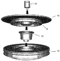
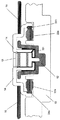
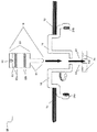
図1は本発明の実施例によるディスクドライブ組立体の分解された状態の斜視図を示し、図2は図1に示す実施例の分解された状態の断面図を示す。図3は図1および2に示す実施例の組み立てられた状態の断面図を示す。 FIG. 1 is an exploded perspective view of a disk drive assembly according to an embodiment of the present invention. FIG. 2 is an exploded sectional view of the embodiment shown in FIG. FIG. 3 shows a cross-sectional view of the embodiment shown in FIGS. 1 and 2 in an assembled state.
図1、図2および図3を参照すれば、カップ12は中央の開放部分76を有するハブ14のくぼみ領域77を回転可能に誘引しながら、基部10に組み立てられる。図2の断面図から容易に判りうるように、全体的にカップ状の構造体(以下「カップ」と称する)12は概ね円筒形であり、底部は密閉されている。ある実施例においては、底部突起71はカップの主要部分73よりも小さい直径としうる。そのような実施例においては、前記底部突起71は基部10の空洞70中へ装嵌しうる。他の実施例において前記底部突起71は省略しうる。カップ12は、鋼、アルミニューム、青銅、あるいは当該技術分野の専門家には周知であるその他の適当な材料からつくりうる。カップ12は圧入、溶接あるいは接着剤によって基部10に固定しうる。ある実施例においては、カップ12はカップリップ74と合流するカップの開放端部に向かって外方へテーパがつけられた側壁を有しうる。この外方へのテーパによって、カップがハブ14と組み立てられると毛管シールを提供する(図4の数字35を参照)。カップリップ74は組み立てられると、ハブ14の隣接する面と共にラビリンスシールを形成することができる。
With reference to FIGS. 1, 2, and 3, the
さて、図2に示す実施例を参照すれば、スピンドル18は本体部分80とカップへの取り付け部分81を含む。スピンドル取付け部分81はハブ14がスピンドル18の周りで回転できるようにするためにハブ14のくぼみ領域77の中央開放部分76を貫通するような形状とされている。スピンドル18の本体部分80は毛管シール部分82と流体力学的ジャーナルベアリング部分32aおよび32bを含む。2個の流体力学的ジャーナルベアリング部分が示されているが、本発明のその他の実施例においては1個の、あるいはいずれかの数の流体力学的ジャーナルベアリングを有しうる。一実施例においては、スピンドル18はカップ12の対応する孔75中へスピンドル部分81を圧入することによってカップ12に取り付けられる。当該技術分野の専門家に周知であるような代替的な取り付け方法も使用しうる。スピンドルは鋼、アルミニューム、あるいは当該技術分野の専門家には周知であるその他の適当な材料からつくりうる。図3から判りうるように、スピンドル18がカップ12に結合され、かつカップ12が基部10に結合されると、ハブ14はスピンドル18によって回転可能に適所に固定される。ハブ14の回転を示す矢印は図2において矢印83によって示される通りである。循環流路101がカップ12とハブ14との境界面の間およびハブ14とスピンドル18の境界面の間で潤滑流体を連通させる。
Referring now to the embodiment shown in FIG. 2, the
図4は図3に示す実施例の細部を示す。本実施例において、カップ12の内面はスピンドル18の面に隣接してスラストベアリング34を提供するようにパターンがつけられている。代替的に、スラストベアリング34に隣接して示されているスピンドル18の面をスラストベアリングとしてつくるようにしてもよい。本実施例においては、2個の毛管シールがある。一方の毛管シール36はハブ14とスピンドル18の間に形成されている。他方の毛管シール35はハブ14とカップ12との間に形成されている。ある実施例においては、カップ12はハブ14およびスピンドル18と組み立てる前に潤滑流体を少なくとも部分的に充填しておくことができる。ハブ14は鋼、アルミニュームあるいは当該技術分野の専門家には周知のその他の適当な材料からつくることができる。
FIG. 4 shows details of the embodiment shown in FIG. In this embodiment, the inner surface of the
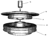
図5はカップ部分42が基部40と一体である本発明の第二の実施例の分解された状態の斜視図を示す。少なくとも1個のディスク16に結合されたハブ14は回転可能に前記カップ部分と組み立てられ、図6において断面図から判るようにスピンドル18によって適所に少なくとも部分的に保持されている。本実施例のその他の構成要素は前述の実施例に関連して前述した通りである。
FIG. 5 shows an exploded perspective view of a second embodiment of the present invention in which the
図7aおよび7bは第三の実施例によるスピンドル、ハブおよびスラストワッシャの組立体の分解した状態の斜視上面図および底面図を示す。ハブ14は少なくとも1個のディスク16に結合されている。スピンドル18は図示のようにハブ14を通して挿入し、スラストワッシャ71に結合することができる。スラストワッシャ71にはスピンドル18と結合するための内孔と、カップ部分42と結合するように形成された外径部と、ハブ14の隣接する面に対して組み立てられるとスラストベアリングとして機能するように構成された流体力学的ベアリングのパターンがつけられた面とを形成することができる。図8は図7に示す実施例の断面図を示す。スピンドル18は圧入、溶接、接着剤あるいは当該技術分野の専門家には周知のその他の方法によってスラストワッシャ71に結合させることができる。
7a and 7b show a perspective top view and a bottom view of the spindle, hub and thrust washer assembly according to the third embodiment in an exploded state.
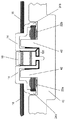
図9は組立て前における、スピンドル、ハブおよびスラストワッシャの組立体93と一体のカップ40を備えた基部との分解された状態の斜視図を示す。図10は図9に示す実施例を断面図で示す。図11は組み立て後の図9に示す実施例を示し、図12は図11の細部を示す。スラストワッシャ71はスラストベアリングとして作用するようにパターンがつけられた面をハブ14に隣接して有する。スラストワッシャ71はまた、図示のようにスピンドル18に隣接して潤滑剤循環流路102を有している。1個の循環流路のみが示されているが、他の実施例においては、1個以上の循環流路を有することができる。その他の実施例では、循環流路をスピンドル18の軸線からより遠位側に備えたスラストワッシャを有しうる。
FIG. 9 shows an exploded perspective view of the spindle, hub and thrust
再び図10を参照すれば、基部40と一体のカップはスピンドル、ハブおよびスラストワッシャの組立体93と組み立てる前に少なくとも部分的に潤滑流体を充填させることができる。
Referring again to FIG. 10, the cup integral with the base 40 can be at least partially filled with lubricating fluid prior to assembly with the spindle, hub and thrust
本発明をある実施例に関して説明してきたが、本発明は本明細書に記載した特定の形態に限定される意図のものではない。例えば、ディスクドライブ記憶装置の実施例が説明されてきたが、その他の実施例はCDドライブ、DVDドライブあるいはその他の用途のためのモータ組立体に適用することも可能である。従って、本発明の範囲はむしろ特許請求の範囲によってのみ限定される。更に、特徴が特定の実施例に関して説明されているように見えるが、当該技術分野の専門家には説明した実施例の各種の特徴が本発明に従って組み合わされうることが認識される。特許請求の範囲において、含まれる請求項目はその他の要素あるいは方法の段階の存在を排除するものではない。 Although the invention has been described with reference to certain embodiments, the invention is not intended to be limited to the specific form set forth herein. For example, while embodiments of disk drive storage devices have been described, other embodiments can be applied to motor assemblies for CD drives, DVD drives, or other applications. Accordingly, the scope of the invention is rather limited only by the scope of the claims. Further, while the features appear to be described with respect to particular embodiments, those skilled in the art will recognize that the various features of the described embodiments can be combined in accordance with the present invention. In the claims, the following claims do not exclude the presence of other elements or method steps.
更に、個々に列挙されているとしても、複数の手段、要素あるいは方法の段階は、例えば単一のユニットあるいはプロセッサによって実行されうる。更に、個々の特徴は諸々の請求項にも含めることは可能であるが、それらは有利なように組合み合わせることも可能であり、諸々の請求項に含めるということは特徴の組み合わせが可能でないとか、および(または)有利でないという意味ではない。請求項の一区分に特徴を含めるということはその区分に対する限定を意味するのではなく、その特徴が適宜、請求項のその他の区分に対しても同等に適用可能であることをむしろ指示しているものである。更に、請求項における特徴の順序は、その特徴を実行する必要のある特定の順序を意味するものではなく、特に、方法の特許請求における個々の段階の順序はそれらの段階がその順序で実行する必要があるということを意味するものではない。むしろ、方法の段階はいずれか適当な順序で実行すればよい。 Furthermore, even if individually listed, a plurality of means, elements or method steps may be implemented by eg a single unit or processor. Further, although individual features may be included in various claims, they may be combined in an advantageous manner, and inclusion in various claims does not allow a combination of features. And / or does not mean not advantageous. Inclusion of a feature in a section of a claim does not imply a limitation on that section, but rather indicates that the feature is equally applicable to other sections of the claim as appropriate. It is what. Furthermore, the order of features in a claim does not imply a particular order in which the features need to be performed, and in particular, the order of the individual steps in a method claim is performed in that order. It does not mean that there is a need. Rather, the method steps may be performed in any suitable order.
提供された図面は単に例示的なものであり、スケール通り作画されていないことがありうる。ある比率は誇張されていたり、一方別の比率は縮小されているかもしれない。図面は当該技術分野の専門家によって理解され、かつ適当に実行することができる本発明の各種の実施を例示する意図のものである。 The drawings provided are merely exemplary and may not be drawn to scale. One ratio may be exaggerated, while another ratio may be reduced. The drawings are intended to illustrate various implementations of the invention that can be understood and appropriately implemented by those skilled in the art.
従って、本発明は特許請求の範囲に記載の精神と範囲内において、修正および変更を加えて実施可能であることを理解すべきである。本説明は厳密なものでなく、本発明を開示された正確な形態に限定する意図のものでない。本発明は修正あるいは変更を加えて実施可能であり、かつ本発明は特許請求の範囲およびそれと同等のものによってのみ限定しうることを理解すべきである。 Therefore, it should be understood that the invention can be practiced with modification and alteration within the spirit and scope of the appended claims. The description is not exact and is not intended to limit the invention to the precise form disclosed. It should be understood that the invention can be practiced with modification or alteration and that the invention be limited only by the claims and the equivalents thereof.
10、40 基部
12、42 カップ
14 ハブ
16 ディスク
18 スピンドル
22a,22b 永久磁石
24a,24b ステータ
34 スラストベアリングパターン
35 毛管シール
36 毛管シール
71 スラストワッシャ
74 リップ
76 中央開口
77 くぼみ部分
81 カップの取付け部分
93 スピンドル、ハブおよびスラストワッシャの組立体
101、102 潤滑流体循環流路
10, 40
Claims (20)
基部、
開放した第一の端部分と、密封された第二の端部分と、少なくとも概ね前記第一の端部分から少なくとも概ね前記第二の端部分まで外方にテーパのついている内面とを含む全体的にカップ状の構造体、
第一と第二の面を有し、その第一の面に流体力学的ベアリングパターンを形成しており、前記スピンドルの結合構造体と結合するような形状とされた中央孔を画成し、外周領域が前記全体的にカップ状の構造体の第二の端部分の内面と結合するような形状とされているスラストワッシャ、
前記スピンドルと前記カップ状構造体との間で回転可能に装嵌するような形状とされたくぼみ領域を含み、前記カップ状の構造体のテーパー付き内面の少なくとも一部に対向した外周面を有し、前記スピンドルの結合構造体がそこを通して前記カップの第二の端部分に固定され、その周りで前記ハブが回転する中央開口を画成しており、かつ前記スピンドルの第二の端領域と隣接してスラストベアリングパターンを含むハブ、
前記ハブの内縁部において交番極性に配置された複数の永久磁石、および
前記複数の永久磁石に近接して前記基部に結合されたステータであって、円形に配置された複数の歯を含み、前記歯の各々が前記ステータを極性化して前記ハブを回転させるべく付勢されるように配備されたコイルすなわち巻き線を支持しているステータを含むことを特徴とするモータ組立体。 A spindle having a diameter, comprising a first end region, a second end region, and at least one journal bearing pattern formed on a peripheral surface thereof, and concentrically from the second region A spindle comprising a coupling structure having a diameter smaller than the diameter of the suspended spindle;
base,
A general including an open first end portion, a sealed second end portion, and an inner surface that tapers outwardly from at least approximately the first end portion to at least approximately the second end portion. Cup-shaped structure,
Having a first and second surface, forming a hydrodynamic bearing pattern on the first surface, defining a central hole shaped to couple with the coupling structure of the spindle; A thrust washer having an outer peripheral region configured to be coupled to the inner surface of the second end portion of the generally cup-shaped structure;
It includes a recessed region shaped to be rotatably fitted between the spindle and the cup-shaped structure, and has an outer peripheral surface facing at least a part of the tapered inner surface of the cup-shaped structure. A coupling structure of the spindle is secured therethrough to a second end portion of the cup, defining a central opening around which the hub rotates, and a second end region of the spindle; A hub containing a thrust bearing pattern, adjacent
A plurality of permanent magnets arranged in alternating polarity at the inner edge of the hub, and a stator coupled to the base in proximity to the plurality of permanent magnets, comprising a plurality of teeth arranged in a circle, A motor assembly comprising a stator supporting a coil or winding disposed such that each tooth is biased to polarize the stator and rotate the hub.
前記ハブのくぼみ領域の外周面と前記の全体的にカップ状の構造体の内面とが毛管シールを形成するような外形とされていることを特徴とする請求項1に記載のモータ組立体。 The outer periphery of the spindle and the inner surface of the indented region of the hub have an outer shape that forms a capillary seal,
2. The motor assembly according to claim 1, wherein an outer peripheral surface of the indented region of the hub and an inner surface of the generally cup-shaped structure are configured to form a capillary seal.
全体的にカップ状の構造体を中に形成した基部であって、前記全体的にカップ状の構造体が第一の端部分と、第二の端部分と、少なくとも概ね前記第一の端部分から少なくとも概ね第二の端部分まで外方にテーパのついている内面とを有している基部、
第一と第二の面を有し、その第一の面に流体力学的ベアリングパターンを形成しており、前記スピンドルの結合構造体と結合するような形状とされた中央孔を画成し、外周領域が前記全体的にカップ状の構造体の第二の端部分の内面と結合するような形状とされているスラストワッシャ、
前記スピンドルと前記カップ状構造体との間で回転可能に装嵌するような形状とされたくぼみ領域を含み、前記カップ状の構造体のテーパー付き内面の少なくとも一部に対向した外周縁面を有し、前記スピンドルの結合構造体がそこを通して前記カップの第二の端部分に固定され、その周りで前記ハブが回転する中央開口を画成しており、かつ前記スピンドルの第二の端領域と隣接してスラストベアリングパターンを含むハブ、
前記ハブの内縁部において交番極性で配置されている複数の永久磁石、および
前記複数の永久磁石に近接して前記基部に結合されたステータであって、円形に配置された複数の歯を含み、前記歯の各々が前記ハブを回転させるべく前記ステータを極性化させるよう付勢されるように装備されたコイルすなわち巻き線を支持するステータを含むことを特徴とするモータ組立体。 A spindle having a diameter, comprising a first end region, a second end region, and at least one journal bearing pattern formed on a peripheral surface thereof, and concentrically from the second region A spindle comprising a coupling structure having a diameter smaller than the diameter of the suspended spindle;
A base having a generally cup-shaped structure formed therein, the generally cup-shaped structure having a first end portion, a second end portion, and at least approximately the first end portion; A base having an inner surface that tapers outward from at least approximately the second end portion;
Having a first and second surface, forming a hydrodynamic bearing pattern on the first surface, defining a central hole shaped to couple with the coupling structure of the spindle; A thrust washer having an outer peripheral region configured to be coupled to the inner surface of the second end portion of the generally cup-shaped structure;
An outer peripheral surface that includes a recessed region shaped to be rotatably fitted between the spindle and the cup-shaped structure, and that faces at least a part of the tapered inner surface of the cup-shaped structure. The spindle coupling structure is secured to a second end portion of the cup therethrough, defining a central opening about which the hub rotates, and a second end region of the spindle A hub containing a thrust bearing pattern, adjacent to
A plurality of permanent magnets arranged with alternating polarity at the inner edge of the hub, and a stator coupled to the base in proximity to the plurality of permanent magnets, comprising a plurality of teeth arranged in a circle; A motor assembly comprising a stator for supporting a coil or winding, each of said teeth being equipped to be biased to polarize said stator to rotate said hub.
The motor assembly according to claim 10, wherein the hub is made of aluminum.
Applications Claiming Priority (2)
| Application Number | Priority Date | Filing Date | Title |
|---|---|---|---|
| US11/317,561 | 2005-12-22 | ||
| US11/317,561 US7679243B2 (en) | 2005-12-22 | 2005-12-22 | Motor assembly with multifunctional components |
Publications (3)
| Publication Number | Publication Date |
|---|---|
| JP2007174895A JP2007174895A (en) | 2007-07-05 |
| JP2007174895A5 JP2007174895A5 (en) | 2010-02-12 |
| JP5160778B2 true JP5160778B2 (en) | 2013-03-13 |
Family
ID=38192798
Family Applications (1)
| Application Number | Title | Priority Date | Filing Date |
|---|---|---|---|
| JP2006343768A Expired - Fee Related JP5160778B2 (en) | 2005-12-22 | 2006-12-21 | Motor assembly with multi-functional components |
Country Status (5)
| Country | Link |
|---|---|
| US (2) | US7679243B2 (en) |
| JP (1) | JP5160778B2 (en) |
| KR (1) | KR101213542B1 (en) |
| CN (1) | CN1992472B (en) |
| SG (2) | SG155940A1 (en) |
Families Citing this family (15)
| Publication number | Priority date | Publication date | Assignee | Title |
|---|---|---|---|---|
| US20030185472A1 (en) * | 2002-03-13 | 2003-10-02 | Aiello Anthony Joseph | Single thrust bearing fluid dynamic bearing motor |
| JP4528677B2 (en) * | 2005-06-24 | 2010-08-18 | 株式会社東芝 | Patterned medium manufacturing method and manufacturing apparatus |
| US7679243B2 (en) * | 2005-12-22 | 2010-03-16 | Seagate Technology Llc | Motor assembly with multifunctional components |
| JP4571593B2 (en) * | 2006-01-30 | 2010-10-27 | アルファナテクノロジー株式会社 | motor |
| US7821167B2 (en) * | 2006-08-09 | 2010-10-26 | Hitachi Global Storage Technologies Netherlands, B.V. | Method and apparatus for increasing the buffer volume in a fluid dynamic bearing |
| US8454238B2 (en) * | 2006-08-23 | 2013-06-04 | Seagate Technology Llc | Spindle regions |
| US8619388B2 (en) * | 2008-04-22 | 2013-12-31 | HGST Netherlands B.V. | Fluid dynamic bearing with an immiscible fluid barrier |
| US20110019303A1 (en) * | 2008-05-26 | 2011-01-27 | Nidec Corporation | Fluid dynamic bearing apparatus, spindle motor, and disk drive apparatus |
| WO2010004828A1 (en) * | 2008-07-08 | 2010-01-14 | Ntn株式会社 | Fluid dynamic pressure bearing device |
| DE102008062524A1 (en) * | 2008-12-16 | 2010-06-17 | Minebea Co., Ltd. | Fluid-dynamic bearing system for rotating spindle motor in hard disk storage drive, has inwardly directed collar fixed in free space under formation of slot, where slot connects axial section of bearing gap with radial section of gap |
| US20110168465A1 (en) * | 2010-01-14 | 2011-07-14 | Gary Starr | Hub wheel motor |
| US8497609B2 (en) * | 2010-10-11 | 2013-07-30 | Alan Lyndon Grantz | Restraining motor shaft play |
| US8858084B2 (en) * | 2011-01-17 | 2014-10-14 | Samsung Electro-Mechanics Japan Advanced Technology Co., Ltd. | Rotating device and component for fluid dynamic bearing unit thereof |
| KR20130073687A (en) * | 2011-12-23 | 2013-07-03 | 삼성전기주식회사 | Spindle motor |
| US9472234B2 (en) * | 2012-10-12 | 2016-10-18 | Marvell International Ltd. | Hard disk drive spindle motor including a base and a base insert formed from different materials |
Family Cites Families (66)
| Publication number | Priority date | Publication date | Assignee | Title |
|---|---|---|---|---|
| US4132414A (en) | 1972-02-07 | 1979-01-02 | Jack Dinsdale | Gramophone turntable apparatus |
| US5134331A (en) * | 1990-05-31 | 1992-07-28 | Nippon Densan Corporation | Spindle motor |
| US5347189A (en) | 1991-09-25 | 1994-09-13 | Nippon Densan Corporation | Spindle motor with labyrinth sealed bearing |
| DE69125836T2 (en) | 1991-11-14 | 1997-12-18 | Quantum Corp | Spindle and hub equipment |
| US5328270A (en) | 1993-03-25 | 1994-07-12 | International Business Machines Corporation | Hydrodynamic pump |
| US5561335A (en) * | 1994-02-25 | 1996-10-01 | Seagate Technology, Inc. | Integrated passive magnetic bearing system and spindle permanent magnet for use in a spindle motor |
| US5427456A (en) | 1994-04-12 | 1995-06-27 | Synektron Corporation | Fluid bearing with asymmetrical groove pattern |
| US6296390B1 (en) | 1994-07-22 | 2001-10-02 | Seagate Technology Llc | Single plate hydrodynamic bearing with extended single journal bearing |
| US5487608A (en) | 1994-07-22 | 1996-01-30 | Seagate Technology, Inc. | Single plate hydrodynamic bearing with self-balancing fluid level and fluid circulation |
| US5977674A (en) | 1994-07-22 | 1999-11-02 | Seagate Technology, Inc. | Single plate hydrodynamic bearing with self-balancing fluid level |
| US5533812A (en) | 1994-07-22 | 1996-07-09 | Seagate Technology, Inc. | Single plate hydrodynamic bearing with self-balancing fluid level |
| US5653540A (en) | 1994-07-22 | 1997-08-05 | Seagate Technology, Inc. | Hydrodynamic bearing assembly with single sided grooved counterplace |
| US5524986A (en) | 1994-08-02 | 1996-06-11 | Seagate Technology, Inc. | Fluid retention principles for hydrodynamic bearings |
| US5423612A (en) | 1994-09-16 | 1995-06-13 | Quantum Corp. | Hydrodynamic bearing and seal |
| US5908247A (en) | 1994-11-14 | 1999-06-01 | Seagate Technology, Inc. | Sinusoidal grooving pattern for grooved journal bearing |
| US5579579A (en) | 1994-12-08 | 1996-12-03 | Quantum Corporation | Method for making precision self-contained hydrodynamic bearing assembly |
| US5956204A (en) | 1995-02-13 | 1999-09-21 | Seagate Technology, Inc. | Magnetic disc drive having magnetic particle trap for hydrodynamic bearing |
| US5969903A (en) | 1995-02-13 | 1999-10-19 | Seagate Technology, Inc. | Magnetic particle trap for hydrodynamic bearing |
| US5793129A (en) | 1995-03-02 | 1998-08-11 | Seagate Technology, Inc. | Low distortion interference fits for spindle motor assembly |
| US5601125A (en) | 1995-07-18 | 1997-02-11 | Seagate Technology, Inc. | Vacuum fill technique for hydrodynamic bearing |
| US5577842A (en) | 1995-08-30 | 1996-11-26 | Seagate Technology, Inc. | Absorbent oil barrier for hydrodynamic bearing |
| US5516212A (en) | 1995-09-18 | 1996-05-14 | Western Digital Corporation | Hydrodynamic bearing with controlled lubricant pressure distribution |
| CN1148859C (en) * | 1995-11-16 | 2004-05-05 | 松下电器产业株式会社 | Motor |
| US5940246A (en) | 1995-11-16 | 1999-08-17 | Seagate Technolog, Inc. | Disc drive hydro bearing lubricant with electrically conductive, non-metallic additive |
| US5678929A (en) | 1996-05-20 | 1997-10-21 | Seagate Technology, Inc. | Grooved hydrodynamic bearing arrangement including a porous lubricant reservoir |
| US5969448A (en) * | 1997-07-03 | 1999-10-19 | Data Storage Institute | Electric spindle motor |
| US5777403A (en) * | 1996-07-30 | 1998-07-07 | Nikon Corporation | Voice coil motor with air guide and air bellows |
| US5714817A (en) | 1996-09-13 | 1998-02-03 | Synektron Corporation | Labyrinth seal system |
| US6144523A (en) | 1996-12-20 | 2000-11-07 | Seagate Technology Llc | Simplified conical bearing with independent flow paths |
| US5847479A (en) | 1997-04-15 | 1998-12-08 | Sae Magnetics (H.K.) Ltd. | Self-pressure-balanced hydrodynamic bearing spindle motor |
| KR20000022527A (en) | 1997-04-24 | 2000-04-25 | 토마스 에프.멀베니 | Spindle motor with fluid dynamic bearing having a journal in combination with a conical bearing (one side open) |
| US6296391B1 (en) | 1997-06-09 | 2001-10-02 | Sankyo Seiki Mfg. Co., Ltd. | Hydrodynamic bearing apparatus |
| US5980113A (en) | 1997-06-11 | 1999-11-09 | Seagate Technology, Inc. | Asymmetric sealing means for fluid dynamic bearings |
| US5925949A (en) * | 1997-08-22 | 1999-07-20 | Samsung Electro Mechanics Co., Ltd. | Disc drive motor with means to center a disc and limit its axial movement |
| US6118620A (en) | 1997-11-05 | 2000-09-12 | Seagate Technology Llc | In-hub spindle motor with separate fluid dynamic bearings |
| US6149161A (en) | 1997-11-06 | 2000-11-21 | Seagate Technology Llc | Grooved pumping seal |
| US6183135B1 (en) | 1998-03-19 | 2001-02-06 | Seagate Technology Llc | Single plate hydrodynamic bearing with self-balancing fluid level and fluid circulation |
| US6019516A (en) | 1998-04-14 | 2000-02-01 | Seagate Technology, Inc. | Crowned conical bearing |
| US6148501A (en) | 1998-04-14 | 2000-11-21 | Seagate Technology Llc | Fabrication means for in-hub spindle with separate fluid dynamic bearings |
| US6149159A (en) | 1998-06-30 | 2000-11-21 | Seagate Technology Llc | High pressure boundary seal |
| US6055126A (en) | 1998-07-06 | 2000-04-25 | Seagate Technology, Inc. | Disc drive having hydrodynamic labyrinth seal and magnet shield |
| JP2000186716A (en) * | 1998-10-08 | 2000-07-04 | Seiko Instruments Inc | Fluid dynamic pressure bearing, spindle motor, and rotor device |
| US6065877A (en) | 1998-10-23 | 2000-05-23 | Seagate Technology, Inc. | Thermal compensation for fluid dynamic bearing using bimetal parts |
| JP4215365B2 (en) * | 1999-02-16 | 2009-01-28 | 株式会社日立グローバルストレージテクノロジーズ | Spindle motor and magnetic disk device using the same |
| US6402383B1 (en) | 1999-02-25 | 2002-06-11 | Seagate Technology, Llc | Design methods for highly efficient high speed fluid dynamic bearing motors |
| US6594883B2 (en) | 2000-11-09 | 2003-07-22 | Seagate Technology Llc | Apparatus and method for setting bearing gaps in an electric motor |
| US6575634B2 (en) | 2001-02-20 | 2003-06-10 | Seagate Technology Llc | Thermal compensation without creep in a hydrodynamic bearing |
| JP2002266852A (en) * | 2001-03-13 | 2002-09-18 | Victor Co Of Japan Ltd | Spindle motor |
| JP2003018792A (en) * | 2001-04-17 | 2003-01-17 | Minebea Co Ltd | Motor |
| US6664685B2 (en) * | 2001-11-16 | 2003-12-16 | Seagate Technology Llc | High adhesion, wear resistant coatings for spindle motors in disk drive/storage applications |
| US6982510B1 (en) | 2001-12-20 | 2006-01-03 | Seagate Technology Llc | Low profile fluid dynamic bearing |
| JP3948651B2 (en) * | 2002-02-07 | 2007-07-25 | 日立粉末冶金株式会社 | Spindle motor |
| US6927515B2 (en) * | 2002-07-17 | 2005-08-09 | Seagate Technology, Llc | Dynamic tilt limiter for fluid dynamic bearings |
| US7073945B2 (en) * | 2002-11-05 | 2006-07-11 | Seagate Technology Llc | Dynamic radial capillary seal |
| US7134792B2 (en) * | 2002-11-05 | 2006-11-14 | Seagate Technology Llc | Single thrust-journal bearing cup fluid dynamic bearing motor |
| US7097360B2 (en) * | 2002-12-03 | 2006-08-29 | Minebea Co. Ltd | Hydrodynamic bearing for a spindle motor |
| US7001074B2 (en) | 2003-04-21 | 2006-02-21 | Seagate Technology Llc | High pressure barrier to oil loss by diffusion |
| JP2004328926A (en) * | 2003-04-25 | 2004-11-18 | Nippon Densan Corp | Motor, and disk drive device |
| US7234868B2 (en) * | 2003-05-07 | 2007-06-26 | Seagate Technology Llc | Radial pumping oil seal for fluid dynamic bearing motor |
| JP2005027431A (en) * | 2003-07-02 | 2005-01-27 | Nippon Densan Corp | Motor |
| TWI231085B (en) * | 2003-09-05 | 2005-04-11 | Sunonwealth Electr Mach Ind Co | Assembling device for an axial tube structure of a motor |
| JP2007511195A (en) * | 2003-11-05 | 2007-04-26 | ジーアンドダブリュー テクノロジーズ,インク. | Motor structure |
| JP2005188644A (en) * | 2003-12-25 | 2005-07-14 | Toshiba Corp | Spindle motor, and disk unit provided therewith |
| US8181348B2 (en) * | 2004-04-01 | 2012-05-22 | Seagate Technology Llc | Shielding fluid reservoirs of fluid dynamic bearing motors |
| KR100517085B1 (en) * | 2004-07-29 | 2005-09-26 | (주)지엔더블유테크놀러지 | Fluid dynamic bearing motor |
| US7679243B2 (en) * | 2005-12-22 | 2010-03-16 | Seagate Technology Llc | Motor assembly with multifunctional components |
-
2005
- 2005-12-22 US US11/317,561 patent/US7679243B2/en active Active
-
2006
- 2006-12-19 SG SG200906249-8A patent/SG155940A1/en unknown
- 2006-12-19 SG SG200609165-6A patent/SG133588A1/en unknown
- 2006-12-21 KR KR1020060131699A patent/KR101213542B1/en active IP Right Grant
- 2006-12-21 JP JP2006343768A patent/JP5160778B2/en not_active Expired - Fee Related
- 2006-12-22 CN CN2006101719949A patent/CN1992472B/en not_active Expired - Fee Related
-
2010
- 2010-02-19 US US12/709,439 patent/US7893585B2/en active Active
Also Published As
| Publication number | Publication date |
|---|---|
| JP2007174895A (en) | 2007-07-05 |
| US20100141071A1 (en) | 2010-06-10 |
| US7679243B2 (en) | 2010-03-16 |
| KR101213542B1 (en) | 2013-01-18 |
| CN1992472B (en) | 2012-07-25 |
| US20070145837A1 (en) | 2007-06-28 |
| SG133588A1 (en) | 2007-07-30 |
| CN1992472A (en) | 2007-07-04 |
| US7893585B2 (en) | 2011-02-22 |
| SG155940A1 (en) | 2009-10-29 |
| KR20070066918A (en) | 2007-06-27 |
Similar Documents
| Publication | Publication Date | Title |
|---|---|---|
| JP5160778B2 (en) | Motor assembly with multi-functional components | |
| US7372663B2 (en) | Lubricated limiter for fluid dynamic bearing motor | |
| JP3609258B2 (en) | motor | |
| JP2011099518A (en) | Fluid dynamic pressure bearing, spindle motor, and disk drive device | |
| KR100672179B1 (en) | Non-recirculating conical fluid dynamic bearing for an electric motor | |
| KR100672177B1 (en) | Low profile thrust journal plate fluid dynamic bearing motor | |
| JP4387114B2 (en) | Bearing mechanism, motor and disk drive | |
| JP2005528873A (en) | Rotating shaft conical fluid dynamic bearing | |
| US20060158778A1 (en) | Spindle motor having a fluid dynamic bearing system | |
| JP2006118531A (en) | Dynamic pressure bearing device, motor using the same and disc driving device | |
| KR20120023860A (en) | Motor | |
| KR101090029B1 (en) | Motor and driving device of recording disk including the same | |
| JP5306086B2 (en) | Disk drive | |
| JP2005016556A (en) | Conical dynamic pressure bearing device, and recording disk drive device having the same | |
| JP2012105521A (en) | Motor and recording disk driving device including the same | |
| JP4275982B2 (en) | Bearing mechanism, motor and disk drive | |
| WO2004084381A1 (en) | Motor and recording medium drive device | |
| KR20140080839A (en) | Spindle motor and hard disk drive including the same | |
| JP2002101610A (en) | Magnetic disk device and motor | |
| KR100826338B1 (en) | Spindle motor | |
| JP3736468B2 (en) | Bearing unit, motor and electronic device having bearing unit | |
| JP2006230095A (en) | Spindle motor and recording disk driving device | |
| JP2004304990A (en) | Motor and disk drive gear | |
| JPH0433494Y2 (en) | ||
| KR20030074395A (en) | Low power spindle motor with a fluid dynamic spool bearing |
Legal Events
| Date | Code | Title | Description |
|---|---|---|---|
| A521 | Written amendment |
Free format text: JAPANESE INTERMEDIATE CODE: A523 Effective date: 20091221 |
|
| A621 | Written request for application examination |
Free format text: JAPANESE INTERMEDIATE CODE: A621 Effective date: 20091221 |
|
| RD03 | Notification of appointment of power of attorney |
Free format text: JAPANESE INTERMEDIATE CODE: A7423 Effective date: 20100526 |
|
| A131 | Notification of reasons for refusal |
Free format text: JAPANESE INTERMEDIATE CODE: A131 Effective date: 20120306 |
|
| A521 | Written amendment |
Free format text: JAPANESE INTERMEDIATE CODE: A523 Effective date: 20120605 |
|
| TRDD | Decision of grant or rejection written | ||
| A01 | Written decision to grant a patent or to grant a registration (utility model) |
Free format text: JAPANESE INTERMEDIATE CODE: A01 Effective date: 20121204 |
|
| A61 | First payment of annual fees (during grant procedure) |
Free format text: JAPANESE INTERMEDIATE CODE: A61 Effective date: 20121213 |
|
| R150 | Certificate of patent or registration of utility model |
Ref document number: 5160778 Country of ref document: JP Free format text: JAPANESE INTERMEDIATE CODE: R150 Free format text: JAPANESE INTERMEDIATE CODE: R150 |
|
| FPAY | Renewal fee payment (event date is renewal date of database) |
Free format text: PAYMENT UNTIL: 20151221 Year of fee payment: 3 |
|
| R250 | Receipt of annual fees |
Free format text: JAPANESE INTERMEDIATE CODE: R250 |
|
| R250 | Receipt of annual fees |
Free format text: JAPANESE INTERMEDIATE CODE: R250 |
|
| R250 | Receipt of annual fees |
Free format text: JAPANESE INTERMEDIATE CODE: R250 |
|
| R250 | Receipt of annual fees |
Free format text: JAPANESE INTERMEDIATE CODE: R250 |
|
| LAPS | Cancellation because of no payment of annual fees |