JP5160271B2 - Housing for underground structures - Google Patents
Housing for underground structures Download PDFInfo
- Publication number
- JP5160271B2 JP5160271B2 JP2008060310A JP2008060310A JP5160271B2 JP 5160271 B2 JP5160271 B2 JP 5160271B2 JP 2008060310 A JP2008060310 A JP 2008060310A JP 2008060310 A JP2008060310 A JP 2008060310A JP 5160271 B2 JP5160271 B2 JP 5160271B2
- Authority
- JP
- Japan
- Prior art keywords
- inner cylinder
- cylinder
- ring body
- circumferential direction
- cylindrical body
- Prior art date
- Legal status (The legal status is an assumption and is not a legal conclusion. Google has not performed a legal analysis and makes no representation as to the accuracy of the status listed.)
- Expired - Fee Related
Links
- 210000000078 claw Anatomy 0.000 claims description 123
- 230000002093 peripheral effect Effects 0.000 claims description 37
- 239000004576 sand Substances 0.000 description 12
- 238000004519 manufacturing process Methods 0.000 description 4
- 238000000034 method Methods 0.000 description 4
- 238000012986 modification Methods 0.000 description 4
- 230000004048 modification Effects 0.000 description 4
- XLYOFNOQVPJJNP-UHFFFAOYSA-N water Substances O XLYOFNOQVPJJNP-UHFFFAOYSA-N 0.000 description 4
- 229910001018 Cast iron Inorganic materials 0.000 description 2
- 238000009434 installation Methods 0.000 description 2
- 238000010586 diagram Methods 0.000 description 1
- 230000003028 elevating effect Effects 0.000 description 1
- 238000003780 insertion Methods 0.000 description 1
- 230000037431 insertion Effects 0.000 description 1
- 238000011900 installation process Methods 0.000 description 1
- 230000002452 interceptive effect Effects 0.000 description 1
Images
Landscapes
- Underground Structures, Protecting, Testing And Restoring Foundations (AREA)
Description
本発明は、固定設置される外筒体と、上下に開口し上方の開口は蓋体によって塞がれる内筒体とを備えた地下構造物用筐体に関する。 The present invention relates to a housing for an underground structure that includes an outer cylinder that is fixedly installed, and an inner cylinder that is open up and down and whose upper opening is closed by a lid.
地中に埋設された水道管等の仕切弁を地上から操作することができるよう、その仕切弁の上には筐体が設置される。この筐体の上端は地面と同じ高さ位置で開口しており、開口は蓋体によって塞がれる。作業時にはこの蓋体を開けて地上から仕切弁を操作する。 A casing is installed on the gate valve so that a gate valve such as a water pipe buried in the ground can be operated from the ground. The upper end of the housing opens at the same height as the ground, and the opening is closed by a lid. When working, the lid is opened and the gate valve is operated from the ground.
従来より、筐体の上端位置を地面と同じ高さ位置に合わせることを容易にするため、外筒体と内筒体を備えたネジ式筐体が用いられている。外筒体は地中に設けられた駆体に固定設置され、内筒体は上下に開口し上方の開口が蓋体によって塞がれる。このネジ式筐体では、内筒体の上方の開口を地面と同じ高さ位置に合わせる必要があり、内筒体の外周面と外筒体の内周面に螺合構造が設けられている。この螺合構造によって、内筒体を周方向に回動することで内筒体が、固定設置された記外筒体の内周面に沿って昇降する。内筒体を回動させその上方の開口の位置が地面と同じ高さ位置に一致すると、内筒体が回動しないように内筒体を固定する必要が生じる。そこで、内筒体の内側に固定爪を設けるとともに内筒体には貫通孔を設け、内筒体の内側からその貫通孔を通して外筒体に固定爪の先端部分を突出させ、内筒体を外筒体に固定する提案がなされている(特許文献1参照)。この提案では、螺合構造として、外筒体の内周面に雌ネジ部を設けるとともに内筒体の外周面に雄ネジ部を設けており、内筒体の雄ネジ部と突出した固定爪先端部分とで外筒体の雌ネジ部を挟み込んで内筒体を外筒体に固定する。固定爪は内筒体の内側に水平方向の回動支点を有し、内筒体の高さ位置調整の際にはその先端部分が突出しないよう、固定爪は内筒体の外周面よりも内側に収納されている。内筒体を外筒体に固定する際には固定爪を水平方向に回動し、内筒体の先端部分が貫通孔を通って外筒体側に突出する。このため、貫通孔は、水平方向に回動する固定爪先端が通過できるよう、内筒体の周方向に大きく開口している。また、内筒体の雄ネジ部と固定爪先端部分とで外筒体の雌ネジ部を挟み込むには、固定爪の上下方向の位置調整を行わなければならず、固定爪の回動支点には上下方向に延びるボルトが設けられている。固定爪は、そのボルトを操作することで水平方向に回動し、さらに上下方向の位置調整の際にも、そのボルトを操作することで固定爪の位置が調整される。内筒体に設けられた貫通孔は、固定爪の上下方向の位置調整を妨げないよう、上下方向に余裕をもった大きさの孔である。
ところで、内筒体の上端は地面と同じ高さ位置にあるが、駆体に固定設置された外筒体の上端は地中にある。このため、外筒体の上端から内筒体と外筒体の間に砂が入り込みやすく、その間に入り込んだ砂は、螺合構造を伝って徐々に下方へ移動してくる。特許文献1に記載された筐体では、貫通孔が、上述のごとく周方向に大きく開口し、上下方向に余裕をもった孔であるため、螺合構造を伝って下方へ移動してきた砂は、その貫通孔から内筒体内側に流れ込む。内筒体内側に流れ込んだ砂が、上記ボルトのネジ溝に挟まると、上記ボルトが操作できなくなり、水平方向の回動や上下方向の位置調整を行うことができなくなる恐れがある。内筒体における上方の開口の位置を地面と同じ高さ位置に合わせて筐体を地中に一旦設置した後でも、地盤沈下や地面の再舗装等によって、内筒体における開口の高さ位置を変更する必要が生じることがある。内筒体の高さ位置を変更する際、砂が上記ボルトのネジ溝に挟まりそのボルトが操作できないと、内筒体の高さ位置を変更することができない。また、貫通孔を有する内筒体を製造することは手間がかかることである。
By the way, the upper end of the inner cylinder is at the same height as the ground, but the upper end of the outer cylinder fixedly installed on the drive unit is in the ground. For this reason, sand easily enters between the inner cylindrical body and the outer cylindrical body from the upper end of the outer cylindrical body, and the sand that has entered therebetween gradually moves downward through the screwing structure. In the case described in
本発明は上記事情に鑑み、容易に製造することができる内筒体を備え、その内筒体の高さ位置を変更することができなくなる可能性を低減させた地下構造物用筐体を提供することを目的とするものである。 In view of the above circumstances, the present invention provides a housing for an underground structure that includes an inner cylinder that can be easily manufactured, and that reduces the possibility that the height position of the inner cylinder cannot be changed. It is intended to do.
上記目的を解決する本発明の第1の地下構造物用筐体は、固定設置される外筒体と、上下に開口し上方の開口は蓋体によって塞がれる内筒体とを備えた地下構造物用筐体において、
上記内筒体を周方向に回動することでその内筒体が上記外筒体の内周面に沿って昇降する螺合構造がその内筒体の外周面とその外筒体の内周面に設けられ、
この地下構造物用筐体がさらに、上記内筒体よりも下方で上記外筒体に接しその内筒体の周方向の回動を阻止する固定爪を備えたことを特徴する。
A first underground structure housing of the present invention that solves the above-described object includes an outer cylinder that is fixedly installed, and an underground cylinder that is open up and down and whose upper opening is closed by a lid. In the housing for structures,
A screwing structure in which the inner cylinder moves up and down along the inner peripheral surface of the outer cylinder by rotating the inner cylinder in the circumferential direction has an outer peripheral surface of the inner cylinder and an inner periphery of the outer cylinder. Provided on the surface,
The underground structure housing further includes a fixing claw that contacts the outer cylinder below the inner cylinder and prevents the inner cylinder from rotating in the circumferential direction.
ここで、上記固定爪は、上記外筒体に強い摩擦力をもって接するものであってもよいし、あるいは、上記外筒体に接することで、その外筒体に対して周方向に係止するものであってもよい。 Here, the fixed claw may be in contact with the outer cylinder body with a strong frictional force, or may be engaged with the outer cylinder body in the circumferential direction by contacting the outer cylinder body. It may be a thing.
本発明の第1の地下構造物用筐体によれば、上記内筒体の周方向の回動を阻止する固定爪は、その内筒体よりも下方で上記外筒体に接触する。このため、上記内筒体に貫通孔を設ける必要がなくなる。また、この第1の地下構造物用筐体では、上記固定爪がボルトの操作によって上記外筒体に接触するものに限られないが、仮に、上記固定爪がそのようなものであった場合にも、そのボルトのネジ溝に砂が挟まることが低減される。すなわち、特許文献1に記載された内筒体の貫通孔よりも下方で上記外筒体に接触する。このため、上記螺合構造を伝って徐々に下方へ移動してくる砂が、上記固定爪を操作するボルトに到達するまでの距離は、特許文献1に記載された地下構造物用筐体よりも本発明の地下構造物用筐体の方が長く、相当の時間を要するため、第1の地下構造物用筐体の方が砂が到達しにくい。したがって、上記内筒体の高さ位置を変更することができなくなる可能性が低減される。しかも、上記内筒体に貫通孔を設ける必要がないため、その内筒体の製造は容易である。
According to the first housing for an underground structure of the present invention, the fixed claw for preventing the inner cylinder from rotating in the circumferential direction contacts the outer cylinder below the inner cylinder. For this reason, it is not necessary to provide a through hole in the inner cylinder. Further, in the first underground structure housing, the fixed claw is not limited to the one that comes into contact with the outer cylinder body by the operation of the bolt, but if the fixed claw is such In addition, it is possible to reduce sand trapped in the screw groove of the bolt. That is, it contacts the outer cylinder below the through hole of the inner cylinder described in
本発明の第1の地下構造物用筐体において、上記固定爪は、上記外筒体の周方向に間隔をあけてその外筒体に向かって複数設けられたものであって、この固定爪の上面がその外筒体に接触するものであることが好ましい。 In the first underground structure housing according to the present invention, a plurality of the fixing claws are provided toward the outer cylinder body at intervals in the circumferential direction of the outer cylinder body. It is preferable that the upper surface of the is in contact with the outer cylinder.
こうすることで、上記固定爪が、上記外筒体の周方向における複数箇所でその外筒体に接し、上記内筒体が水平方向にガタつくことを抑えることができる。 By carrying out like this, the said fixed nail | claw can contact the outer cylinder body in the several places in the circumferential direction of the said outer cylinder body, and it can suppress that the said inner cylinder body rattles in a horizontal direction.
ここで、上記固定爪が、上記内筒体とは別体のものであることが好ましい。 Here, it is preferable that the fixed claw is separate from the inner cylinder.
上記固定爪を別体にすることで、上記内筒体の製造がより容易になる。 By making the fixed claw separate, the inner cylinder can be manufactured more easily.
また、本発明の第1の地下構造物用筐体において、上記固定爪が、上記内筒体とは別に上記外筒体の周方向に回動するものである態様がさらに好ましい。 In the first underground structural housing of the present invention, it is more preferable that the fixed claw is rotated in the circumferential direction of the outer cylinder separately from the inner cylinder.
上記固定爪が上記内筒体とともに回動するものであると、内筒体の周方向の回動位置に上記固定爪の位置が大きく拘束されることになる。このため、上記固定爪の、上記外筒体に接触する位置が、所定位置に定められている場合に、上記固定爪の位置をその所定位置に合わせるために内筒体を回動させて、内筒体の高さ位置をかなりずらさなければならないことがある。しかしながら、上記固定爪が上記内筒体とは別に回動する態様であれば、内筒体の周方向の回動位置に上記固定爪の位置が多少は拘束されることがあっても大きく拘束されることはなく、内筒体の高さ位置を微調整することができる。 If the fixed claw rotates together with the inner cylinder, the position of the fixed claw is largely restricted by the circumferential rotation position of the inner cylinder. For this reason, when the position of the fixed claw that is in contact with the outer cylinder is set to a predetermined position, the inner cylinder is rotated to adjust the position of the fixed claw to the predetermined position. The height position of the inner cylinder may have to be shifted considerably. However, if the fixed claw is rotated in a manner separate from the inner cylinder, the position of the fixed claw may be slightly restricted by the circumferential rotation position of the inner cylinder. The height position of the inner cylinder can be finely adjusted.
さらに、本発明の第1の地下構造物用筐体において、上記内筒体の内側に配置され、その内筒体とは別に上記外筒体の周方向に回動するリング体を備え、
上記固定爪が、上記リング体の周方向に間隔をあけて複数設けられたものであり、
上記リング体は、上記固定爪が設けられた周方向の間隔よりも狭いピッチで周方向に段階的に位置を変えて上記内筒体に係合するものである態様がより好ましい。
Further, in the first underground structure housing of the present invention, the casing is disposed inside the inner cylindrical body, and includes a ring body that rotates in the circumferential direction of the outer cylindrical body separately from the inner cylindrical body,
A plurality of the fixing claws are provided at intervals in the circumferential direction of the ring body,
It is more preferable that the ring body is engaged with the inner cylindrical body by changing its position stepwise in the circumferential direction at a pitch narrower than a circumferential interval provided with the fixing claws.
この態様によれば、内筒体の高さ位置の微調整を妨げることなく上記固定爪が設けられた上記リング体が上記内筒体に係合し、上記リング体と上記内筒体の相対的な周方向のズレが確実に防止される。 According to this aspect, the ring body provided with the fixing claw engages with the inner cylinder body without interfering with fine adjustment of the height position of the inner cylinder body, and the ring body and the inner cylinder body are relative to each other. In the circumferential direction is surely prevented.
上記目的を解決する本発明の第2の地下構造物用筐体は、固定設置される外筒体と、上下に開口し上方の開口は蓋体によって塞がれる内筒体とを備えた地下構造物用筐体において、
上記内筒体を周方向に回動することでその内筒体が上記外筒体の内周面に沿って昇降する螺合構造がその内筒体の外周面とその外筒体の内周面に設けられ、
この地下構造物用筐体がさらに、上記内筒体の内側に配置され、その内筒体とは別に上記外筒体の周方向に回動するリング体と、
上記リング体に設けられ、上記外筒体に接し上記内筒体の周方向の回動を阻止する固定爪とを備えたことを特徴とする。
The second case for the underground structure of the present invention that solves the above-described object comprises an outer cylinder body that is fixedly installed and an inner cylinder body that is open up and down and whose upper opening is closed by a lid body. In the housing for structures,
A screwing structure in which the inner cylinder moves up and down along the inner peripheral surface of the outer cylinder by rotating the inner cylinder in the circumferential direction has an outer peripheral surface of the inner cylinder and an inner periphery of the outer cylinder. Provided on the surface,
This underground structure casing is further arranged inside the inner cylinder, and separately from the inner cylinder, a ring body that rotates in the circumferential direction of the outer cylinder,
A fixing claw provided on the ring body and in contact with the outer cylinder body to prevent rotation of the inner cylinder body in the circumferential direction is provided.
本発明の第2の地下構造物用筐体によれば、上記リング体は上記内筒体とは別体であり、上記内筒体の製造が容易になる。また、上記リング体が別体であることから設計の自由度が増し、その内筒体の高さ位置を変更することができなくなる可能性を低減させることができる。さらには、上記固定爪が設けられたリング体は上記内筒体とは別に回動するため、その内筒体の周方向の回動位置に上記固定爪の位置が多少は拘束されることがあっても大きく拘束されることはなく、内筒体の高さ位置を微調整することができる。 According to the second casing for an underground structure of the present invention, the ring body is separate from the inner cylindrical body, and the manufacturing of the inner cylindrical body becomes easy. Further, since the ring body is a separate body, the degree of freedom in design increases, and the possibility that the height position of the inner cylinder cannot be changed can be reduced. Furthermore, since the ring body provided with the fixed claw rotates separately from the inner cylinder, the position of the fixed claw may be somewhat restrained by the circumferential rotation position of the inner cylinder. Even if it exists, it is not restrained greatly, and the height position of the inner cylinder can be finely adjusted.
また、この第2の地下構造物用筐体において、上記固定爪が、上記リング体の周方向に間隔をあけて複数設けられたものであり、
上記リング体は、上記固定爪が設けられた周方向の間隔よりも狭いピッチで周方向に段階的に位置を変えて上記内筒体に係合するものであることが好ましい。
Further, in this second underground structure housing, a plurality of the fixing claws are provided at intervals in the circumferential direction of the ring body,
It is preferable that the ring body is engaged with the inner cylindrical body by changing its position stepwise in the circumferential direction at a pitch narrower than a circumferential interval provided with the fixing claws.
本発明の第2の地下構造物用筐体における高さ位置調整方法は、上下に開口し上方の開口は蓋体によって塞がれる内筒体を周方向に回動することによりその内筒体が外筒体の内周面に沿って昇降する螺合構造がその内筒体の外周面とその外筒体の内周面に設けられた地下構造物用筐体の高さ位置調整方法において、
上記外筒体を固定設置する外筒体固定工程と、
上記内筒体の内側に、その内筒体とは別に上記外筒体の周方向に回動するリング体を設置するリング体設置工程と、
上記内筒体を回動させ、その内筒体の高さ位置の調整を行う高さ位置調整工程と、
上記内筒体の内側で、上記外筒体の周方向に対する上記リング体の位置決めを行うリング体位置決め工程と、
上記外筒体に接し上記内筒体の周方向の回動を阻止する固定爪を、上記リング体に取り付ける固定爪取付工程とを有することを特徴とする。
According to the second method of adjusting the height position of the housing for an underground structure of the present invention, the inner cylinder is rotated by rotating the inner cylinder that opens up and down and the upper opening is closed by the lid in the circumferential direction. In a method for adjusting the height position of a casing for an underground structure in which a screwing structure in which an elevating and lowering along the inner peripheral surface of the outer cylindrical body is provided on the outer peripheral surface of the inner cylindrical body and the inner peripheral surface of the outer cylindrical body ,
An outer cylinder fixing step for fixing and installing the outer cylinder;
On the inside of the inner cylinder, a ring body installation step of installing a ring body that rotates in the circumferential direction of the outer cylinder separately from the inner cylinder,
A height position adjusting step of rotating the inner cylinder and adjusting the height position of the inner cylinder;
A ring body positioning step for positioning the ring body with respect to the circumferential direction of the outer cylinder inside the inner cylinder,
A fixing claw attaching step of attaching to the ring body a fixing claw that is in contact with the outer cylinder and prevents rotation of the inner cylinder in the circumferential direction.
ここで、上記固定爪取付工程において上記固定爪を上記リング体に取り付けると、その固定爪が上記外筒体に接する態様であってもよいが、別途、内筒体固定工程を設け、この工程で上記固定爪を上記外筒体に接触させ、上記内筒体の周方向の回動を阻止するようにしてもよい。 Here, when the fixing claw is attached to the ring body in the fixing claw attaching step, the fixing claw may be in contact with the outer cylindrical body, but a separate inner cylinder fixing step is provided. Then, the fixing claw may be brought into contact with the outer cylinder so as to prevent the rotation of the inner cylinder in the circumferential direction.
また、この地下構造物用筐体の高さ位置調整方法において、上記外筒体固定工程は、外側に窪んだ凹部が内周面に設けられた外筒体を固定設置する工程であり、
上記リング体設置工程が、先端部分が上記凹部よりも内側に位置する第2固定爪が取り付けられたリング体を上記内筒体の内側に設置する工程であって、
上記固定爪取付工程が、上記固定爪の先端部分を上記外周筒の凹部に差し込み、その凹部に先端部分が差し込まれた状態の固定爪を上記リング体に取り付ける工程であることが好ましい。
Further, in the height position adjusting method of the underground structure casing, the outer cylindrical body fixing step is a step of fixing and installing the outer cylindrical body in which the concave portion recessed outward is provided on the inner peripheral surface,
The ring body installation step is a step of installing the ring body to which the second fixed claw whose tip portion is located on the inner side of the concave portion is attached inside the inner cylindrical body,
It is preferable that the fixing claw attaching step is a step of inserting the tip end portion of the fixing claw into the concave portion of the outer peripheral cylinder and attaching the fixing claw in a state where the tip portion is inserted into the concave portion to the ring body.
ここでも、内筒体固定工程を設け、この工程で上記固定爪を上記外筒体に接触させるとともに上記第2固定爪も上記外筒体に接触させてもよい。 Here, an inner cylinder fixing step may be provided, and in this step, the fixing claw may be brought into contact with the outer cylinder and the second fixing claw may be brought into contact with the outer cylinder.
また、この地下構造物用筐体の高さ位置調整方法において、上記外筒体固定工程は、外側に窪んだ凹部が内周面の周方向に間隔をあけて複数設けられた外筒体を固定設置する工程であり、
上記リング体位置決め工程は、上記凹部が設けられた周方向の間隔よりも狭いピッチで上記リング体を周方向にずらしてそのリング体を上記内筒体に係合させることで、そのリング体の位置決めを行う工程であることも好ましい。
Further, in this height structure adjusting method of the housing for underground structures, the outer cylinder fixing step includes an outer cylinder in which a plurality of concave portions recessed outward are provided at intervals in the circumferential direction of the inner peripheral surface. Fixed installation process,
In the ring body positioning step, the ring body is shifted in the circumferential direction at a pitch narrower than the circumferential interval provided with the recesses, and the ring body is engaged with the inner cylindrical body, thereby It is also preferable to be a step of positioning.
本発明によれば、容易に製造することができる内筒体を備え、その内筒体の高さ位置を変更することができなくなる可能性を大幅に低減させた地下構造物用筐体を提供することができる。 According to the present invention, there is provided a housing for an underground structure that includes an inner cylinder that can be easily manufactured and greatly reduces the possibility that the height position of the inner cylinder cannot be changed. can do.
以下図面を参照して本発明の実施の形態を説明する。 Embodiments of the present invention will be described below with reference to the drawings.
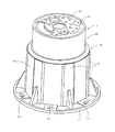
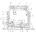
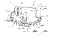
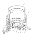
図1は、本発明の地下構造物用筐体の一実施形態である、ネジ式仕切弁筐の斜視図であり、図2は、図1に示すネジ式仕切弁筐の断面図である。 FIG. 1 is a perspective view of a screw type gate valve housing which is an embodiment of the underground structure housing of the present invention, and FIG. 2 is a cross-sectional view of the screw type gate valve housing shown in FIG.
図1に示すネジ式仕切弁筐1は、外筒体10と内筒体20を有する二重筒構造体であり、地中に設置される。外筒体10も内筒体20もいずれも鋳鉄製のものである。外筒体10は、不図示の躯体にボルトによって固定設置される。この外筒体10は、下部フランジ11を有し、その下部フランジ11には、躯体にボルト止めする際にボルトを通す固定用孔111が周方向に沿って等間隔に設けられている。また、外筒体10の外周面101には、周方向に60°間隔で6つの張出部12が設けられている。
A screw type
図2に示すように、内筒体20は上下に開口20a,20bを有し、上方の開口20aは蓋体9によって塞がれる。図1に示すネジ式仕切弁筐1は、地中に埋設された水道管等の仕切弁(不図示)の上に設置され、仕切弁を操作する場合には、この蓋体9を開けて仕切弁を操作する。また、ネジ式仕切弁筐1では、蓋体9の上面91を地面と同じ高さ位置に合わせるため、内筒体20の上方の開口20aが地面と同じ高さ位置になるように内筒体20の高さ位置調整が行われる。ネジ式仕切弁筐1には、この高さ位置調整を容易にするため、外筒体10の内周面102と内筒体20の外周面201とに螺合構造30が設けられている。
As shown in FIG. 2, the
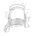
図3は、外筒体と内筒体を上下方向に沿って切断した状態を表す斜視図である。 FIG. 3 is a perspective view illustrating a state in which the outer cylinder and the inner cylinder are cut along the vertical direction.
本実施形態のネジ式仕切弁筐1では、螺合構造30として、外筒体10の内周面102には雌ネジ部31が設けられており、内筒体20の外周面201には雄ネジ部32が設けられている。したがって、不図示の躯体に固定設置された外筒体10に対して、内筒体20を周方向に回動させることで、その内筒体20は昇降し、内筒体20の上方の開口20aを地面と同じ高さ位置に容易に合わせることができる。外筒体10の内周面102に設けられた雌ネジ部31のネジ溝311には、外筒体10の周方向に60°間隔で、外側に窪んだ凹部312が設けられている。これらの凹部312は、外筒体10の張出部12の位置に合わせて設けられており、外周面101に張出部12がある所には、内周面102に凹部312があることになる。また、内筒体20の内周面202の下端部分には、内筒体20の周方向に120°間隔で突出部21が3つ設けられている。
In the screw type
また、図2に示すように、本実施形態のネジ式仕切弁筐1はリング体40も有する。リング体40は、外筒体10や内筒体20とは別体のものであり、内筒体20の内側に配置される。このリング体40には、1つの長固定爪51と、図2には一つしか図示されていないが2つの短固定爪52とがそれぞれボルト41によって取り付けられる。以下、これらの長固定爪51と短固定爪52を総称して単に固定爪と称することがある。
As shown in FIG. 2, the screw type
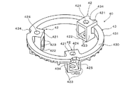
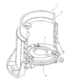
図4は図2に示すリング体を見たときの斜視図であり、図5は図2に示すリング体を上下逆さまにして見たときの斜視図である。 4 is a perspective view when the ring body shown in FIG. 2 is viewed, and FIG. 5 is a perspective view when the ring body shown in FIG. 2 is viewed upside down.
リング体40には、図2に示す固定爪(51,52)を取り付けるための取付部42が周方向に120°間隔で3つ設けられている。各取付部42は、リング体40の環状部43の外周縁431よりも内側に設けられている。これらの取付部42はいずれも、上壁421、底壁422、および周方向に間隔をあけて設けられた1対の側壁423を有するが、いずれの取付部42にも、リング体40の半径方向外側となる外壁や内側となる内壁は設けられておらず外側も内側も開口している。また、これら3つの取付部42は高さ位置が異なる。すなわち、図4の右奧に示された取付部42は、上壁421が環状部43よりも上にあり、3つの取付部42のうちで最も高い位置に設けられたものである。リング体40を内筒体20の内側に配置した状態では、この右奧の取付部42が、内筒体20上方の開口20a(図2参照)に最も近いものになる。一方、図4の手前に示された取付部42と左奧に示された取付部42はともに、上壁421が環状部43の上面430と同じ高さにあるが、左奧の取付部42の方が手前の取付部42よりも下方に長く、左奧の取付部42が3つの取付部42のうちで最も低い位置に設けられたものである。3つの取付部42の高さ位置関係は、外筒体10に設けられた雌ネジ部31のリード角に適合させた関係である。上壁421と底壁422には、図2に示すボルト41が上下方向に挿通するボルト孔424が設けられている。各固定爪(51,52)には、ボルト41と螺合するネジ溝510(図2参照)が設けられている。図2に示すように、固定爪(51,52)は、このボルト孔424に挿通したボルト41によって取付部42に、先端部分511,521が外側を向いた姿勢で取り付けられる。すなわち、ボルト41によって取付部42に取り付けられた固定爪(51,22)はいずれも、取付部42の外側の開口425から外側に向かって延びた状態にある。図4に示すリング体40では、右奧に示された最も高い位置にある取付部42に図2に示す長固定爪51が取り付けられ、残りの2つの取付部42に短固定爪52が取り付けられる。その結果、長固定爪51が最も高い位置で外側に向かって延びたものになり、左奧の取付部42に取り付けられた短固定爪52が最も低い位置で外側に向かって延びたものになる。リング体40の取付部42に取り付けられた長固定爪51は、短固定爪52よりも外側に向かって長く延びたものである。なお、各固定爪(51,52)をどの取付部42に取り付けるかは自由であるが、後述する作業性の観点から、ここでは、上方の開口20a(図2参照)に最も近くなる右奧の取付部42に長固定爪51を取り付ける。
The
また、図5に示すように、環状部43の下面432における、取付部42と取付部42の間には、周方向に6個の小突起433が並んでいる。すなわち、取付部42に取り付けられた隣り合う固定爪(51,52)の周方向の間隔よりも狭いピッチで小突起433が並んでいる。これらの小突起433は10°間隔で設けられている。隣り合う小突起433と小突起433の間には、図3に示す内筒体20の内周面202に設けられた突出部21が嵌め込まれる。上述の如く、内筒体20に設けられた突出部21は、内筒体20の周方向に120°間隔で3つ設けられている。リング体40は、3箇所の、隣り合う小突起433と小突起433の間それぞれに、これら3つの突出部21それぞれが嵌め込まれることで、内筒体20に安定した状態で支持される。すなわち、リング体40は、内筒体20の周方向3箇所で内筒体20に係合する。こうして内筒体20に係合したリング体40は、周方向に回動不能である。また、6個の小突起433と取付部42との間には大突起435が設けられている。小突起433の突出長が5mmであるのに対して、この大突起435の突出長は13mmである。
As shown in FIG. 5, six
さらに、環状部43には、取付部42が設けられた位置に切欠部434が設けられている。切欠部434は、内側に切り欠かれた部位である。図4に示すリング体40は、2つの短固定爪52を取付部42に取り付けた状態で、図3に示す内筒体20の下方から内筒体20の内側に配置される。リング体40を内筒体20の下方の開口20bから入れる際、内筒体20の内周面202に設けられた突出部21と干渉しないよう、この切欠部434を内筒体20の突出部21に合わせた状態でリング体40を内筒体20の内側に配置する。
Further, the
本実施形態のネジ式仕切弁筐1では、内筒体20を周方向に回動することで内筒体20の高さ位置調整が行われ、その高さ位置調整が終わると、内筒体20が回動しないようにその内筒体20を外筒体10に固定する。
In the screw type
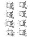
図6は、本実施形態のネジ式仕切弁筐における、内筒体の高さ位置調整から内筒体の固定までの様子を段階的に示した図である。 FIG. 6 is a diagram showing in a stepwise manner the state from the height position adjustment of the inner cylinder to the fixing of the inner cylinder in the screw type gate valve housing of the present embodiment.
図6(a)は、本実施形態のネジ式仕切弁筐1における初期状態を示す。この初期状態では、外筒体10は不図示の躯体にボルト止めされている。また、内筒体20は最も低い位置にある。さらに、内筒体20の内側にはリング体40が配置されている。リング体40は、内筒体20に係合しており、内筒体20に回動不能に支持されている。リング体40に設けられた3つの取付部42のうち、2つの取付部42それぞれにはボルト41によって短固定爪52が取り付けられているが、このボルト41は完全に締め込まれた状態ではなく、ある程度緩んだ状態にある。また、3つの取付部42のうち、残り一つの、上方の開口20aに最も近くなる取付部42には、長固定爪51がまだ取り付けられていない。
Fig.6 (a) shows the initial state in the screw type
図6(a)に示す初期状態から図6(b)に示すように、内筒体20を周方向に回動して内筒体20を上昇させ、内筒体20の上方の開口20aが地面と同じ高さ位置になるように内筒体20の高さ位置調整を行う。すなわち、内筒体20の上縁200と周囲の地面との間に段差がないように、内筒体20の高さ位置を調整する。内筒体20を回動する際、リング体40に取り付けられた短固定爪52の先端521は、外筒体10の雌ネジ部31におけるネジ山313とネジ山313の間に位置し、外筒体10には接触しておらず、短固定爪52によって内筒体20の回動が妨げられることはない。
As shown in FIG. 6B from the initial state shown in FIG. 6A, the
内筒体20の高さ位置調整が終わると、図6(c)に示すようにリング体40を、図3に示す内筒体20の内周面202に設けられた突出部21との嵌合が外れるまで持ち上げる。すなわち、上述のごとくリング体40に設けられた小突起433の突出長が5mmであることから、リング体40を5mmより高く持ち上げる。ここで、リング体40を10mm持ち上げると、短固定爪52の先端521が外筒体10の雌ネジ部31におけるネジ山313にぶつかり、リング体40は10mmより高くは持ち上がらない。こうして、リング体40の、内筒体20との係合を一旦外す。
When the height position adjustment of the inner
内筒体20との係合が外されたリング体40は、内筒体20の内側で周方向に60°の範囲で回動自在であり、図6(d)に示すようにリング体40を周方向に回動する。この際、内筒体20は回動せずに、リング体40のみが回動する。図5に示すように、リング体40の位置調整のための回動可能範囲(調整可能範囲)は60°である。上述のごとく、10mmまでしか持ち上げられないリング体40を、図5に示す調整可能範囲を超えて回動しようとしても、そのリング体40に設けられた、突出長13mmの大突起435が、内筒体20の突出部21にぶつかり、上記調整可能範囲を超えて回動することが規制される。これは、外筒体10の内周面102に設けられた凹部312が周方向に60°間隔で設けられているため、リング体40は最大でも60°回動させればよいことに起因する。リング体40を回動するにあたっては、外筒体10の外周面101に設けられた張出部12の位置に、リング体40の取付部42がくるように回動する。上述のごとく、外筒体10の内周面102に設けられた凹部312は、外筒体10の張出部12の位置に合わせて設けられているため、このように回動することで、短固定爪52における先端部分521の位置が、凹部312(図6(d)で図示した凹部とは異なる凹部)が設けられた位置に合致する。
The
リング体40の位置合わせが終了したら、図6(e)に示すようにリング体40を降ろす。リング体40を降ろすと、リング体40に設けられた、3箇所の、隣り合う小突起433と小突起433の間それぞれに、内筒体20に設けられた3つの突出部21(図3参照)それぞれが嵌め込まれ、リング体40が内筒体20に係合し、リング体40は内筒体20に回動不能に支持される。ここで、リング体40が内筒体20にうまく係合しない場合には、リング体40をわずかに(10°未満の角度)回動することで、リング体40が内筒体20に係合する。それでもリング体40が内筒体20に係合しない場合には、内筒体20を10°回動させる。本実施形態におけるネジ式仕切弁筐1では、図5に示すようにリング体40における小突起433の間と間の間隔が、内筒体20を高さ位置調整するにあたっての最小調整範囲になり、その回動角度は10°である。内筒体20を1周回動させると、30mm高さ位置が変わる場合であれば、内筒体20を10°回動させると0.83mm高さ位置が変わってしまうが、1mm未満の範囲で地面との高さ調整が可能になる。このように細かな調整ができることによって、内筒体20の高さ位置調整が極めて容易になる。短固定爪52の先端部分は内筒体20よりも下方に位置する。
When the alignment of the
次いで、図6(f)に示すように、長固定爪51が取り付けられていなかった取付部42に、内側の開口426から長固定爪51を挿入する。長固定爪51を挿入するにあたっては、上方の開口20aから手を入れて挿入する。長固定爪51が取り付けられていなかった取付部42は、3つの取付部42のうち、その上方の開口20aに最も近い取付部42であり、長固定爪51を挿入しやすい。挿入された長固定爪51の先端部分は凹部312(図6(d)で図示した凹部とは異なる凹部)内に入り込む。なおここで、長固定爪51がうまく挿入できない場合には、先のリング体40の位置合わせが適切に行われていないことになり、この場合には、再度、リング体40の位置合わせを行えばよい。長固定爪51の先端部分も内筒体20よりも下方に位置する。
Next, as shown in FIG. 6 (f), the long fixed
長固定爪51の挿入が終わると、図6(g)に示すように、長固定爪51を挿入した取付部42にボルト41を差し込み、最後に、図6(h)に示すように、3つの取付部42のボルト41を均等に締め込む。ネジ溝510が設けられた固定爪(51,52)は、ボルト41を締め込むことにより上昇し、図2に示す長固定爪51と2つの短固定爪52それぞれの先端部分511,521の上面511a,521aは、外筒体10における雌ネジ部31のネジ山313に下方から接する。すなわち、固定爪(51,52)の先端部分511,521は、内筒体20よりも下方で外筒体10に接する。このように、長固定爪51と2つの短固定爪52が周方向に120°間隔で外筒体10に接することにより、内筒体20の水平方向のガタつきが防止される。しかも、図2に示すように、外筒体10における雌ネジ部31のネジ山313は、内筒体20における雄ネジ部32のネジ山323と、長固定爪51の先端部分511とで挟み込まれる。また、外筒体10のネジ山313は、内筒体20のネジ山323と、2つの短固定爪52の先端部分521それぞれとによっても挟み込まれ、合計3箇所で挟み込まれる。したがって、内筒体20の水平方向のガタつきは確実に防止され、さらに、内筒体20の周方向への回動も確実に防止される。
When the insertion of the long fixed
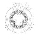
図7は、内筒体の固定を終えた状態のネジ式仕切弁筐の底面図である。 FIG. 7 is a bottom view of the screw type gate valve housing in a state where the inner cylindrical body has been fixed.
図7に示すネジ式仕切弁筐1は、外筒体10のフランジ11側(下方)から見た図である。この図7には、4時の方向と8時の方向を向いた短固定爪52と、12時の方向を向いた長固定爪51が示されている。これらの固定爪(51,52)は、外筒体10の周方向に間隔をあけてその外筒体10に向かって複数設けられている。また、短固定爪52の先端部分521は、外筒体10の内周面102に設けられた凹部312に入り込んでいないが、長固定爪51の先端部分511は、その凹部312に入り込んでいる。図7に示す長固定爪51の先端部分511は、凹部312のちょうど真ん中(周方向中央部分)に入り込んでおり、その凹部312を画定する側壁3121には接していないが、仮に、少しずれて長固定爪51の先端部分511が凹部312に入り込むと、その先端部分511は凹部312の側壁3121に接する。側壁3121に接した長固定爪51によって、内筒体20の、その側壁3121側への回動が阻止される。
The screw type
また、本実施形態のネジ式仕切弁筐1が長期間にわたって使用され、長固定爪51を取り付けているボルト41が万が一緩んだとしても、長固定爪51の、凹部312内に入り込んだ先端部分511がその側壁3121に当接し、内筒体20の回動が阻止される。
Further, even if the screw type
図7には、取付部42に短固定爪52を取り付けているボルト41の下端に嵌め込まれた、ボルト抜け止め防止用のスナップリング44が示されている。
FIG. 7 shows a
図8は、本実施形態のネジ式仕切弁筐に中蓋が設置された様子を示す図である。 FIG. 8 is a view showing a state in which an inner lid is installed in the screw type gate valve housing of the present embodiment.
地中に埋設された水道管等の仕切弁(不図示)の上に設置される切弁筐では、仕切弁に砂等がかからないように中蓋を設けることがある。内筒体20に回動不能に支持されたリング体40は、この中蓋6の受枠としても機能する。図7に示す中蓋6は、リング体40の上面形状に沿った形状である。
In a cut-off valve housing installed on a gate valve (not shown) such as a water pipe buried in the ground, an inner lid may be provided so that sand or the like is not applied to the gate valve. The
以上説明した本実施形態のネジ式仕切弁筐1では、内筒体20に貫通孔が設けられていない。また、内筒体20よりも下方で固定爪(51,52)が外筒体10に接するため、取付部42に固定爪(51,52)を取り付けているボルト41の位置も下側になる。このため、螺合構造30を伝って徐々に下方へ移動してくる砂が、そのボルト41に到達するまでには相当の時間を要し、砂がボルト41に到達しにくい。したがって、本実施形態のネジ式仕切弁筐1によれば、砂がボルト41のネジ溝に挟まりにくく、内筒体20の高さ位置を変更することができなくなる可能性が低減される。しかも、鋳鉄製の内筒体20に貫通孔を設ける必要がなく、また、内筒体20に固定爪(51,52)の取付部42を一体に設ける必要もないため、中子形状が簡単になり、その内筒体20の製造が容易になる。
In the screw type
また、本実施形態のネジ式仕切弁筐1によれば、リング体40を、外筒体10に設けられた凹部312と、その凹部312と隣り合う凹部312との間(60°の範囲)で回動すればよい。リング体40を360°回動させようとすると、短固定爪52の先端521は30mm高さ方向に変動することになる。一方、本実施形態のように、リング体40が60°回動すれば足りるようにしておけば、短固定爪52の先端521は5mm高さ方向に変動するだけですみ、ボルト41の操作時間が短時間ですむ。
Further, according to the screw type
なお、ここでの説明では、地中に埋設された水道管等の仕切弁の上に設置される切弁筐を例にあげて説明したが、本発明は切弁筐に限定されることなく広く地下構造物用筐体に適用することができる。また、本実施形態では、長固定爪51の他、2つの短固定爪52を設けたが、先端部分511が外筒体10の凹部312に入り込む長固定爪51だけであっても、内筒体20の周方向の回動は阻止することができ、短固定爪52を省略してもよい。さらに、長固定爪51を複数設けてもよく、短固定爪52も1個あるいは3個以上設けてもよい。ただし、上面511a,521aが、外筒体10における雌ネジ部31のネジ山313に接する固定爪51,52を複数(好ましくは3個以上)設けることで、内筒体20の水平方向のガタ付きが防止される。
In the description here, the explanation has been given by taking as an example the cut-off valve housing installed on the gate valve such as a water pipe buried in the ground, but the present invention is not limited to the cut-off valve housing. It can be widely applied to housing for underground structures. Further, in this embodiment, the two short
続いて、本実施形態のネジ式仕切弁筐の変形例について説明する。以下の変形例の説明においては、これまで説明した構成要素と同じ名前の構成要素には、これまで使用した符号と同じ符号を用いる。また、これまでの説明と重複する説明については省略する。 Subsequently, a modified example of the screw type gate valve housing of the present embodiment will be described. In the following description of the modified examples, the same reference numerals as those used so far are used for components having the same names as the components described so far. Moreover, the description which overlaps with the description so far is abbreviate | omitted.
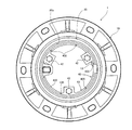
図9は、本実施形態のネジ式仕切弁筐の変形例を示す斜視図であり、図10は、変形例のネジ式仕切弁筐の平面図である。 FIG. 9 is a perspective view showing a modified example of the screw type gate valve housing of the present embodiment, and FIG. 10 is a plan view of the modified screw type gate valve housing.
図9には、リング体40の位置合わせを終えた状態のネジ式仕切弁筐1が示されている。また、図10には、内筒体20の固定を終えた状態のネジ式仕切弁筐1を、内筒体20の上方の開口20a側から見た様子が示されている。
FIG. 9 shows the screw type
この変形例のネジ式仕切弁筐1は、リング体40の位置合わせをより容易にするための工夫が施されている。図9に示すリング体40における環状部43の上面430には、周方向に60°間隔で位置合わせ用マーク435が6個設けられている。位置合わせ用マーク435は三角形の窪みである。また、図9に示す外筒体10の内周面102における下部には、位置合わせ用突起13が1本設けられている。この変形例では、この位置合わせ用突起13の位置に、リング体40に設けられた6個の位置合わせ用マーク435のいずれか一つがくると、リング体40の取付部42が、外筒体10の内周面102に設けられた凹部312(図9で図示した凹部とは異なる凹部)に対向するようになっている。図9および図10には、位置合わせ用マーク435が位置合わせ用突起13の位置に合った状態が示されている。したがって、この変形例では、リング体40の位置合わせを行う際に、リング体40を周方向に回動させ、リング体40の位置合わせ用マーク435を外筒体10の位置合わせ用突起13に合わせれば、図9に示す短固定爪52における先端部分521の位置が、凹部312(図9で図示した凹部とは異なる凹部)が設けられた位置に合致し、さらには、後で取り付ける、ここでは不図示の長固定爪51における先端部分511の位置も、凹部312(図9で図示した凹部とは異なる凹部)が設けられた位置に合致する。
The screw type
なお、位置合わせ用マーク435は、三角形の窪みに限らず、どのような目印であってもよい。
The
1 ネジ式仕切弁筐
10 外筒体
20 内筒体
21 突出部
20a,20b 開口
30 螺合構造
31 雌ネジ部
312 凹部
32 雄ネジ部
40 リング体
41 ボルト
42 取付部
433 小突起
51 長固定爪
52 短固定爪
DESCRIPTION OF
Claims (2)
前記内筒体を周方向に回動することで該内筒体が前記外筒体の内周面に沿って昇降する螺合構造が該内筒体の外周面と該外筒体の内周面に設けられ、
この地下構造物用筐体がさらに、前記内筒体よりも下方で前記外筒体に接し該内筒体の周方向の回動を阻止する固定爪を備え、
前記固定爪は、前記外筒体の周方向に間隔をあけて該外筒体に向かって複数設けられたものであって、前記内筒体とは別に前記外筒体の周方向に沿って回動し、この固定爪の上面が該外筒体に接触するものであることを特徴とする地下構造物用筐体。 In the case for an underground structure including an outer cylinder that is fixedly installed, and an inner cylinder that is opened up and down and the upper opening is closed by a lid,
A screwing structure in which the inner cylinder moves up and down along the inner peripheral surface of the outer cylinder by rotating the inner cylinder in the circumferential direction is an outer peripheral surface of the inner cylinder and an inner periphery of the outer cylinder. Provided on the surface,
The underground structure housing further includes a fixing claw that contacts the outer cylindrical body below the inner cylindrical body and prevents circumferential rotation of the inner cylindrical body ,
A plurality of the fixing claws are provided toward the outer cylindrical body at intervals in the circumferential direction of the outer cylindrical body, and along the circumferential direction of the outer cylindrical body separately from the inner cylindrical body A housing for an underground structure that rotates and the upper surface of the fixed claw comes into contact with the outer cylinder .
前記固定爪が、前記リング体の周方向に間隔をあけて複数設けられたものであり、
前記リング体は、前記固定爪が設けられた周方向の間隔よりも狭いピッチで周方向に段階的に位置を変えて前記内筒体に係合するものであることを特徴とする請求項1記載の地下構造物用筐体。 A ring body that is disposed inside the inner cylinder body and rotates in a circumferential direction of the outer cylinder body separately from the inner cylinder body;
A plurality of the fixing claws are provided at intervals in the circumferential direction of the ring body,
2. The ring body according to claim 1, wherein the ring body changes its position stepwise in the circumferential direction at a pitch narrower than a circumferential interval provided with the fixed claws, and engages with the inner cylinder body. Enclosure for underground structure as described.
Priority Applications (1)
| Application Number | Priority Date | Filing Date | Title |
|---|---|---|---|
| JP2008060310A JP5160271B2 (en) | 2008-03-10 | 2008-03-10 | Housing for underground structures |
Applications Claiming Priority (1)
| Application Number | Priority Date | Filing Date | Title |
|---|---|---|---|
| JP2008060310A JP5160271B2 (en) | 2008-03-10 | 2008-03-10 | Housing for underground structures |
Publications (2)
| Publication Number | Publication Date |
|---|---|
| JP2009215777A JP2009215777A (en) | 2009-09-24 |
| JP5160271B2 true JP5160271B2 (en) | 2013-03-13 |
Family
ID=41187900
Family Applications (1)
| Application Number | Title | Priority Date | Filing Date |
|---|---|---|---|
| JP2008060310A Expired - Fee Related JP5160271B2 (en) | 2008-03-10 | 2008-03-10 | Housing for underground structures |
Country Status (1)
| Country | Link |
|---|---|
| JP (1) | JP5160271B2 (en) |
Cited By (1)
| Publication number | Priority date | Publication date | Assignee | Title |
|---|---|---|---|---|
| US12180667B2 (en) | 2019-09-19 | 2024-12-31 | Trevor Brien | Height adjustment mechanism for a manhole assembly and manhole assembly comprising the same |
Families Citing this family (1)
| Publication number | Priority date | Publication date | Assignee | Title |
|---|---|---|---|---|
| CN115749585B (en) * | 2022-10-20 | 2025-07-22 | 重庆大学溧阳智慧城市研究院 | Drilling equipment suitable for cast-in-situ pipe pile construction and application method thereof |
Family Cites Families (2)
| Publication number | Priority date | Publication date | Assignee | Title |
|---|---|---|---|---|
| JP2722381B2 (en) * | 1995-12-28 | 1998-03-04 | 長島鋳物株式会社 | Anti-rotation device in screw type housing |
| JP3515090B2 (en) * | 2001-10-30 | 2004-04-05 | 日之出水道機器株式会社 | Housing for underground structures |
-
2008
- 2008-03-10 JP JP2008060310A patent/JP5160271B2/en not_active Expired - Fee Related
Cited By (1)
| Publication number | Priority date | Publication date | Assignee | Title |
|---|---|---|---|---|
| US12180667B2 (en) | 2019-09-19 | 2024-12-31 | Trevor Brien | Height adjustment mechanism for a manhole assembly and manhole assembly comprising the same |
Also Published As
| Publication number | Publication date |
|---|---|
| JP2009215777A (en) | 2009-09-24 |
Similar Documents
| Publication | Publication Date | Title |
|---|---|---|
| US20090147388A1 (en) | Vehicle exterior rear-view mirror | |
| KR20070076494A (en) | Differential housing | |
| JP5160271B2 (en) | Housing for underground structures | |
| JP2021512749A (en) | Fixed placement for WC flap elements | |
| JP2005163816A (en) | Solenoid valve, its mounting and fixing method, and component mounting fixture for mounting and fixing solenoid valve, sensor, potentiometer, flow sensor and other accessory parts | |
| JP4951598B2 (en) | Housing for underground structures | |
| KR20030087918A (en) | Mechanism for restricting a rotatable angle in rotary valves and an actuator having the mechanism | |
| JP2009108698A (en) | Valve operating device and support member | |
| JP2009114684A (en) | Lock for manhole cover | |
| JP2009007757A (en) | Housing for underground structures | |
| KR20090072953A (en) | Handlebar devices for car boards | |
| KR20050095265A (en) | A hinge assembly for refrigerator | |
| KR101055953B1 (en) | Lower hinge assembly for the door | |
| JPS6123989Y2 (en) | ||
| JP3708071B2 (en) | Screw type housing | |
| CN216447024U (en) | An engine gear chamber assembly | |
| JP4645913B2 (en) | Board case for gaming machines | |
| KR100951977B1 (en) | Fuel door opener mounting structure | |
| KR100737465B1 (en) | Spacer Installation | |
| JP3163108U (en) | Installation position adjusting device for driving type square drain | |
| KR200262256Y1 (en) | Fixing apparatus of faucet for sink | |
| US8596483B2 (en) | Rotatable access closure element | |
| JP2009235744A (en) | Adjuster bolt structure | |
| CN222927291U (en) | Protection box assembly and transformer | |
| JPS602448Y2 (en) | Gas lighter flame length regulating device |
Legal Events
| Date | Code | Title | Description |
|---|---|---|---|
| A621 | Written request for application examination |
Free format text: JAPANESE INTERMEDIATE CODE: A621 Effective date: 20100713 |
|
| A977 | Report on retrieval |
Free format text: JAPANESE INTERMEDIATE CODE: A971007 Effective date: 20120113 |
|
| A131 | Notification of reasons for refusal |
Free format text: JAPANESE INTERMEDIATE CODE: A131 Effective date: 20120131 |
|
| A521 | Request for written amendment filed |
Free format text: JAPANESE INTERMEDIATE CODE: A523 Effective date: 20120312 |
|
| TRDD | Decision of grant or rejection written | ||
| A01 | Written decision to grant a patent or to grant a registration (utility model) |
Free format text: JAPANESE INTERMEDIATE CODE: A01 Effective date: 20121127 |
|
| A61 | First payment of annual fees (during grant procedure) |
Free format text: JAPANESE INTERMEDIATE CODE: A61 Effective date: 20121212 |
|
| R150 | Certificate of patent or registration of utility model |
Ref document number: 5160271 Country of ref document: JP Free format text: JAPANESE INTERMEDIATE CODE: R150 Free format text: JAPANESE INTERMEDIATE CODE: R150 |
|
| FPAY | Renewal fee payment (event date is renewal date of database) |
Free format text: PAYMENT UNTIL: 20151221 Year of fee payment: 3 |
|
| S531 | Written request for registration of change of domicile |
Free format text: JAPANESE INTERMEDIATE CODE: R313531 |
|
| R350 | Written notification of registration of transfer |
Free format text: JAPANESE INTERMEDIATE CODE: R350 |
|
| R250 | Receipt of annual fees |
Free format text: JAPANESE INTERMEDIATE CODE: R250 |
|
| R250 | Receipt of annual fees |
Free format text: JAPANESE INTERMEDIATE CODE: R250 |
|
| R250 | Receipt of annual fees |
Free format text: JAPANESE INTERMEDIATE CODE: R250 |
|
| R250 | Receipt of annual fees |
Free format text: JAPANESE INTERMEDIATE CODE: R250 |
|
| R250 | Receipt of annual fees |
Free format text: JAPANESE INTERMEDIATE CODE: R250 |
|
| R250 | Receipt of annual fees |
Free format text: JAPANESE INTERMEDIATE CODE: R250 |
|
| LAPS | Cancellation because of no payment of annual fees |