JP5157983B2 - Vehicle aerodynamic force calculation device, vehicle motion analysis device, and vehicle suspension control device - Google Patents
Vehicle aerodynamic force calculation device, vehicle motion analysis device, and vehicle suspension control device Download PDFInfo
- Publication number
- JP5157983B2 JP5157983B2 JP2009070426A JP2009070426A JP5157983B2 JP 5157983 B2 JP5157983 B2 JP 5157983B2 JP 2009070426 A JP2009070426 A JP 2009070426A JP 2009070426 A JP2009070426 A JP 2009070426A JP 5157983 B2 JP5157983 B2 JP 5157983B2
- Authority
- JP
- Japan
- Prior art keywords
- vehicle
- coefficient
- fluctuation component
- acquisition means
- term
- Prior art date
- Legal status (The legal status is an assumption and is not a legal conclusion. Google has not performed a legal analysis and makes no representation as to the accuracy of the status listed.)
- Expired - Fee Related
Links
Images


Landscapes
- Vehicle Body Suspensions (AREA)
Description
本発明は、車両空気力算出装置、車両運動解析装置及び車両サスペンション制御装置に係り、特に、走行中の車両に作用する空気力を算出する車両空気力算出装置およびこれを用いる車両運動解析装置と車両サスペンション制御装置に関する。 The present invention relates to a vehicle aerodynamic force calculation device, a vehicle motion analysis device, and a vehicle suspension control device, and in particular, a vehicle aerodynamic force calculation device that calculates aerodynamic force acting on a running vehicle, and a vehicle motion analysis device using the same. The present invention relates to a vehicle suspension control device.
車両の乗り心地あるいは操縦安定性の改善等のために、車両の走行中の運動解析が行われ、これに基づいてサスペンション機構の制御等が行われる。車両は走行中に空気力の作用を受けるので、その影響も考慮される。 In order to improve the ride comfort or steering stability of the vehicle, a motion analysis while the vehicle is running is performed, and the suspension mechanism is controlled based on this analysis. Since the vehicle is subjected to the action of aerodynamic force while traveling, the influence is also taken into consideration.
例えば、特許文献1には、能動型サスペンションとして、走行中の空気抵抗によって車体に発生する上下方向の力を推定し、推定値に応じて圧力制御弁に対する指令値を補正することが開示されている。これにより、車体に与えられる空気抵抗力が変化して各車輪に加えられる上下方向の力が変動しても、車高の変動を防止でき、良好な車体姿勢を維持することができると述べられている。
For example,
また、特許文献2には、車両のサスペンション制御装置として、車両の揚力係数およびピッチングモーメント係数に対するヒービング方向、ピッチング方向の空力微係数を考慮した車両の運動方程式を立てて、これによって車両速度の増加減少による車両のサスペンションの見かけのバネ定数および減衰定数の変化量を演算することが述べられている。 Further, in Patent Document 2, as a vehicle suspension control device, an equation of motion of a vehicle that takes into account the aerodynamic coefficient in the heaving direction and the pitching direction with respect to the lift coefficient and the pitching moment coefficient of the vehicle is established, thereby increasing the vehicle speed. It is stated that the amount of change in the apparent spring constant and damping constant of the vehicle suspension due to the reduction is calculated.
具体的には、ヒービング運動方向の外力とピッチング運動方向の外力を、ヒービング変位量、ピッチング角変位量、ヒービング変位速度、ピッチング角変位速度に比例するものとして求めることが述べられている。そして、求められたヒービング運動方向の外力を並進運動の運動方程式の外力に組み込み、ピッチング運動方向の外力を回転運動の運動方程式の外力に組み込み、得られた演算結果を車両速度がゼロ、つまり空気力が作用しないときの演算結果と等価になるように、車両のサスペンションの見かけのばね定数を算出して、実際のばね定数との差を、空気力の作用による見かけのばね定数の変化量とすることが述べられている。 Specifically, it is described that the external force in the direction of the heaving motion and the external force in the direction of the pitching motion are obtained as being proportional to the amount of displacement of the heaving, the amount of pitching angular displacement, the heaving displacement speed, and the pitching angle displacement speed. The obtained external force in the direction of heaving motion is incorporated into the external force in the translational motion equation, the external force in the pitching motion direction is incorporated into the external force in the rotational motion equation, and the calculated result is zero, that is, the air Calculate the apparent spring constant of the suspension of the vehicle so that it is equivalent to the calculation result when no force is applied, and the difference from the actual spring constant is the amount of change in the apparent spring constant due to the action of the aerodynamic force. It is stated that
また、非特許文献1には、緩やかな姿勢変化に対する準定常空力モデル、および急激な姿勢変化に対する空力弾性係数モデルを、汎用機構解析ソフトADAMSに組み込んで、車両運動解析を行うことが開示されている。
Non-Patent
上記のように従来技術において、車両の運動解析に際し、走行中に受ける空気力の影響を考慮することが行われている。特許文献1では、車体に作用する上下力として車体に発生する揚力を推定するときに車両の姿勢変化を考慮していない。特許文献2では車両の姿勢変化として姿勢と姿勢変化速度を考慮しているが、姿勢変化加速度は考慮していない。非特許文献1における準定常空力モデル、空力弾性係数モデルも変位と変位速度、変位角と変位角速度の関数でとどまっている。
As described above, in the prior art, the influence of the aerodynamic force received during traveling is taken into consideration when analyzing the motion of a vehicle. In
このように従来技術においては、空気力による外力が、変位と比例関係にあるとする定常空力モデル、変位と変位速度との比例関係にあるとする準定常空力モデル等に基づいている。 As described above, the conventional technology is based on a stationary aerodynamic model in which an external force due to aerodynamic force is in a proportional relationship with displacement, a quasi-stationary aerodynamic model in which a proportional relationship between displacement and displacement speed is used, and the like.
流体関連振動を取り扱う分野では、従来から変位加速度に比例する項として、流体力によって対象物に仮想的な質量が加わったものと考えたときのその付加質量の影響が考慮されており、また、非定常翼理論からも平板翼に作用する流体力が変位加速度にも比例関係とするモデルの導出がされている。この場合でも、構造物が水中で振動する場合のように流体の密度が空気の1000倍程度大きい場合、飛行船等のように空気の質量が機体質量に比較して無視できない場合を除いて、付加質量項は余り取り上げられていない。また、大気中を走行する車両についても、付加質量、すなわち変位加速度の影響は無視されてきているのが現状である。 In the field of handling fluid-related vibrations, the influence of the added mass when considering that a virtual mass is added to the object by the fluid force as a term proportional to the displacement acceleration has been considered. From the unsteady blade theory, a model has been derived in which the fluid force acting on the flat blade is proportional to the displacement acceleration. Even in this case, when the density of the fluid is about 1000 times larger than the air, such as when the structure vibrates in water, it is added unless the mass of the air is not negligible compared to the airframe mass, such as an airship. The mass term is not taken up much. In addition, for vehicles traveling in the atmosphere, the effect of additional mass, that is, displacement acceleration has been ignored.
今回、風洞実験および数値シミュレーションによる結果と従来モデルによる計算結果との比較から、車両が加速度運動、特に上下加速度運動する場合には、加速度の影響として付加質量を考慮することが実験結果とよく適合することが見出された。これは、固体壁面としての地面の影響により、大気中を巡航する航空機の場合よりも、付加質量の影響が大きくなるためと考えられる。しかし、上記のように、従来技術では、付加質量の影響を取り入れた動的空力モデルの検討がなされていない。 From the comparison of the results of wind tunnel experiments and numerical simulations with the calculation results of the conventional model, it is well suited to consider the additional mass as an influence of acceleration when the vehicle is accelerating, especially vertical acceleration. It was found to be. This is considered to be because the influence of the added mass becomes larger than that of an aircraft cruising in the atmosphere due to the influence of the ground as a solid wall surface. However, as described above, in the prior art, a dynamic aerodynamic model that takes into account the effect of added mass has not been studied.
本発明の目的は、走行中の車両に作用する空気力をさらに適切に算出できる車両空気力算出装置を提供することである。他の目的は、その車両空気力算出装置を用いる車両運動解析装置及び車両サスペンション制御装置を提供することである。 An object of the present invention is to provide a vehicle aerodynamic force calculation device that can more appropriately calculate the aerodynamic force acting on a running vehicle. Another object is to provide a vehicle motion analysis device and a vehicle suspension control device using the vehicle aerodynamic force calculation device.
本発明に係る車両空気力算出装置は、空気密度ρと、車両速度Uと、車両の前面投影面積Aと、車両の代表長さLと、特性半径Rとを取得する条件取得手段と、車両の基準姿勢における基準揚力係数からの変動成分である揚力係数変動成分をΔCZとし、車両の基準姿勢における基準ピッチングモーメント係数からの変動成分であるピッチングモーメント係数変動成分をΔCMYとして、揚力係数変動成分ΔCZとピッチングモーメント係数変動成分ΔCMYのそれぞれを、上下変位zとピッチ変位角θを入力変数として、各入力変数の2階微分までの項による線形モデルとしてモデル化するモデル化手段と、条件取得手段によって取得した条件と、モデル化された線形モデルとに基づいて、揚力係数変動成分ΔCZとピッチングモーメント係数変動成分ΔCMYをそれぞれ算出する変動成分算出手段と、算出された揚力係数変動成分ΔCZとピッチングモーメント係数変動成分ΔCMYとに基づいて、車両に作用する上下力とピッチングモーメントをそれぞれ算出する作用量算出手段と、を備え、モデル化手段は、2階微分項として、少なくとも上下変位zを入力変数としたときの揚力係数変動成分ΔCZに関する加速度項を有する線形モデルとしてモデル化することを特徴とする。 The vehicle aerodynamic force calculation apparatus according to the present invention includes a condition acquisition means for acquiring an air density ρ, a vehicle speed U, a front projection area A of the vehicle, a representative length L of the vehicle, and a characteristic radius R, The lift coefficient fluctuation component, which is a fluctuation component from the reference lift coefficient in the reference posture of the vehicle, is ΔC Z, and the pitching moment coefficient fluctuation component, which is the fluctuation component from the reference pitching moment coefficient in the vehicle reference posture, is ΔC MY. Modeling means for modeling each of the component ΔC Z and the pitching moment coefficient variation component ΔC MY as a linear model with terms up to the second derivative of each input variable, with the vertical displacement z and the pitch displacement angle θ as input variables; and conditions acquired by the condition acquisition unit, based on the modeled linear model, the lift coefficient variation component [Delta] C Z and pitching moment coefficient variation formed A fluctuation component calculation means for calculating [Delta] C MY, respectively, based on the calculated lift coefficient and variation component [Delta] C Z and pitching moment coefficient variation component [Delta] C MY, effect level calculation for calculating respectively a vertical force and pitching moment acting on the vehicle And the modeling means is modeled as a linear model having an acceleration term related to a lift coefficient fluctuation component ΔC Z when at least vertical displacement z is an input variable as a second-order differential term. .
また、本発明に係る車両空気力算出装置は、空気密度ρと、車両速度Uと、車両の前面投影面積Aと、車両の代表長さLと、特性半径Rとを取得する条件取得手段と、車両の基準姿勢における基準横力係数からの変動成分である横力係数変動成分をΔCYとし、車両の基準姿勢における基準ヨーイングモーメント係数からの変動成分であるヨーイングモーメント係数変動成分をΔCMZとして、横力係数変動成分ΔCYとヨーイングモーメント係数変動成分ΔCMZのそれぞれを、横変位yとヨー変位角βを入力変数として、各入力変数の2階微分までの項による線形モデルとしてモデル化するモデル化手段と、条件取得手段によって取得した条件と、モデル化された線形モデルとに基づいて、横力係数変動成分ΔCYとヨーイングモーメント係数変動成分ΔCMZをそれぞれ算出する変動成分算出手段と、算出された横力係数変動成分ΔCYとヨーイングモーメント係数変動成分ΔCMZとに基づいて、車両に作用する横力とヨーイングモーメントをそれぞれ算出する作用量算出手段と、を備え、モデル化手段は、2階微分項として、少なくとも横変位yを入力変数としたときの横力係数変動成分ΔCYに関する加速度項を有する線形モデルとしてモデル化することを特徴とする。 Further, the vehicle aerodynamic force calculation apparatus according to the present invention includes a condition acquisition unit that acquires an air density ρ, a vehicle speed U, a front projection area A of the vehicle, a representative length L of the vehicle, and a characteristic radius R. the lateral force coefficient variation component which is the fluctuation component from the reference lateral force coefficient in the reference posture of the vehicle and [Delta] C Y, the yawing moment coefficient variation component which is the fluctuation component from the reference yawing moment coefficient in the reference posture of the vehicle as a [Delta] C MZ Each of the lateral force coefficient fluctuation component ΔC Y and the yawing moment coefficient fluctuation component ΔC MZ is modeled as a linear model with terms up to the second derivative of each input variable with the lateral displacement y and the yaw displacement angle β as input variables. and modeling means, and conditions acquired by the condition acquisition unit, based on the modeled linear model, the lateral force coefficient variation component [Delta] C Y and yawing moment coefficient variation Based minute [Delta] C MZ on the fluctuation component calculating means for calculating each of the calculated lateral force coefficient and variation component [Delta] C Y and yawing moment coefficient variation component [Delta] C MZ, act of calculating respectively the lateral force and yawing moment acting on the vehicle comprising a quantity calculating means, the modeling means, as second-order differential term, to model a linear model having an acceleration section in the lateral force coefficient variation component [Delta] C Y when an input variable at least lateral displacement y Features.
また、本発明に係る車両空気力算出手段において、線形モデル化されたモデルにおける加速度項の係数を実車あるいは模型を用いた風洞実験または数値シミュレーションに基づいて取得する加速度項係数取得手段を備え、モデル化手段は、取得された加速度項係数を用いて線形モデル化を行うことが好ましい。 The vehicle aerodynamic force calculation means according to the present invention further includes acceleration term coefficient acquisition means for acquiring a coefficient of an acceleration term in a linear model based on a wind tunnel experiment or a numerical simulation using a real vehicle or a model. The converting means preferably performs linear modeling using the acquired acceleration term coefficient.
また、本発明に係る車両空気力算出装置において、条件取得手段はさらに車両の代表体積Vを取得し、上下変位zを入力変数としたときの揚力係数変動成分ΔCZの加速度項の効果を車両が加速度運動をする際に周囲の空気から受ける付加質量力であると考え、その付加質量を車両によって排除される空気の質量で無次元化した値である付加質量係数について、実車あるいは模型を用いた風洞実験または数値シミュレーションまたは文献値に基いて取得する付加質量係数取得手段を備え、モデル化手段は、加速度項係数を、付加質量係数と車両の代表体積Vとの積として扱うことが好ましい。 Further, in the vehicle aerodynamic force calculation apparatus according to the present invention, the condition acquisition means further acquires the representative volume V of the vehicle, and the effect of the acceleration term of the lift coefficient fluctuation component ΔC Z when the vertical displacement z is an input variable. It is assumed that this is the additional mass force received from the surrounding air during acceleration motion, and the actual mass or model is used for the additional mass coefficient, which is the value obtained by making the additional mass dimensionless by the mass of air excluded by the vehicle. It is preferable that an additional mass coefficient acquisition unit that acquires a wind tunnel experiment, a numerical simulation, or a literature value is used, and the modeling unit treats the acceleration term coefficient as a product of the additional mass coefficient and the representative volume V of the vehicle.
本発明に係る車両空気力算出装置において、条件取得手段はさらに車両の代表体積Vを取得し、横変位yを入力変数としたときの横力係数変動成分ΔCYの加速度項の効果を車両が加速度運動をする際に周囲の空気から受ける付加質量力であると考え、その付加質量を車両によって排除される空気の質量で無次元化した値である付加質量係数について、実車あるいは模型を用いた風洞実験または数値シミュレーションまたは文献値に基いて取得する付加質量係数取得手段を備え、モデル化手段は、加速度項係数を、付加質量係数と車両の代表体積Vとの積として扱うことが好ましい。 In the vehicle air force calculating device according to the present invention, to get a representative volume V of condition acquiring means further vehicle, the vehicle effects acceleration term of the lateral force coefficient variation component [Delta] C Y when the lateral displacement y and the input variables Considering that it is an additional mass force received from the surrounding air during acceleration motion, the actual mass or model was used for the additional mass coefficient, which is a value obtained by making the additional mass dimensionless by the mass of air excluded by the vehicle. It is preferable that an additional mass coefficient acquisition unit that is acquired based on a wind tunnel experiment, a numerical simulation, or a literature value is provided, and the modeling unit treats the acceleration term coefficient as a product of the additional mass coefficient and the representative volume V of the vehicle.
また、本発明に係る車両空気力算出装置において、条件取得手段は、揚力係数変動成分ΔCZの速度項に含まれる特性半径RP12、またはピッチングモーメント係数変動成分ΔCMYの速度項に含まれる特性半径RP22の少なくとも一方を、実車あるいは模型を用いた風洞実験または数値シミュレーションに基づいて取得する特性半径取得手段を含み、変動成分算出手段は、特性半径取得手段によって取得された特性半径の値を用いて、ピッチ変位角θを入力変数としたときの揚力係数変動成分ΔCZとピッチングモーメント係数変動成分ΔCMYを算出することが好ましい。 In the vehicle aerodynamic force calculation apparatus according to the present invention, the condition acquisition means includes a characteristic radius R P12 included in the speed term of the lift coefficient fluctuation component ΔC Z or a characteristic included in the speed term of the pitching moment coefficient fluctuation component ΔC MY. It includes characteristic radius acquisition means for acquiring at least one of the radius RP22 based on a wind tunnel experiment or numerical simulation using an actual vehicle or model, and the fluctuation component calculation means calculates the value of the characteristic radius acquired by the characteristic radius acquisition means. It is preferable to calculate the lift coefficient variation component ΔC Z and the pitching moment coefficient variation component ΔC MY when the pitch displacement angle θ is used as an input variable.
また、本発明に係る車両空気力算出装置において、条件取得手段は、横力係数変動成分ΔCYの速度項に含まれる特性半径RY12、またはヨーイングモーメント係数変動成分ΔCMZの速度項に含まれる特性半径RY22の少なくとも一方を、実車あるいは模型を用いた風洞実験または数値シミュレーションに基づいて取得する特性半径取得手段を含み、変動成分算出手段は、特性半径取得手段によって取得された特性半径の値を用いて、ヨー変位角βを入力変数としたときの横力係数変動成分ΔCYとヨーイングモーメント係数変動成分ΔCMZを算出することが好ましい。 In the vehicle aerodynamic force calculation apparatus according to the present invention, the condition acquisition means is included in the characteristic radius R Y12 included in the speed term of the lateral force coefficient fluctuation component ΔC Y or in the speed term of the yawing moment coefficient fluctuation component ΔC MZ. Characteristic radius acquisition means for acquiring at least one of the characteristic radius RY22 based on a wind tunnel experiment or numerical simulation using an actual vehicle or a model, and the fluctuation component calculation means is a value of the characteristic radius acquired by the characteristic radius acquisition means Is preferably used to calculate the lateral force coefficient fluctuation component ΔC Y and the yawing moment coefficient fluctuation component ΔC MZ when the yaw displacement angle β is an input variable.
本発明に係る車両運動解析装置は、空気密度ρと、車両速度Uと、車両の前面投影面積Aと、車両の代表長さLと、特性半径Rとを取得する条件取得手段と、車両の基準姿勢における基準揚力係数からの変動成分である揚力係数変動成分をΔCZとし、車両の基準姿勢における基準ピッチングモーメント係数からの変動成分であるピッチングモーメント係数変動成分をΔCMYとして、揚力係数変動成分ΔCZとピッチングモーメント係数変動成分ΔCMYのそれぞれを、上下変位zとピッチ変位角θを入力変数として、各入力変数の2階微分までの項による線形モデルとしてモデル化するモデル化手段と、条件取得手段によって取得した条件と、モデル化された線形モデルとに基づいて、揚力係数変動成分ΔCZとピッチングモーメント係数変動成分ΔCMYをそれぞれ算出する変動成分算出手段と、算出された揚力係数変動成分ΔCZとピッチングモーメント係数変動成分ΔCMYとに基づいて、車両に作用する上下力とピッチングモーメントをそれぞれ算出する作用量算出手段と、算出された上下力とピッチングモーメントを車両に作用する外力として、車両の運動方程式に組み込み、車両の運動解析を実行する運動方程式解析手段と、を備え、モデル化手段は、2階微分項として、少なくとも上下変位zを入力変数としたときの揚力係数変動成分ΔCZに関する加速度項を有する線形モデルとしてモデル化することを特徴とする。 A vehicle motion analysis apparatus according to the present invention includes an air density ρ, a vehicle speed U, a front projection area A of a vehicle, a representative length L of the vehicle, and a condition radius R for acquiring a characteristic radius R, The lift coefficient fluctuation component, which is the fluctuation component from the reference lift coefficient in the reference posture, is ΔC Z, and the pitching moment coefficient fluctuation component, which is the fluctuation component from the reference pitching moment coefficient, in the vehicle reference attitude is ΔC MY , the lift coefficient fluctuation component Modeling means for modeling each of ΔC Z and pitching moment coefficient variation component ΔC MY as a linear model with terms up to second derivative of each input variable, with vertical displacement z and pitch displacement angle θ as input variables, and conditions Based on the condition acquired by the acquisition means and the modeled linear model, the lift coefficient variation component ΔC Z and the pitching moment coefficient variation component Δ Based C MY to a fluctuation component calculation means for calculating each of the calculated lift coefficient and variation component [Delta] C Z and pitching moment coefficient variation component [Delta] C MY, effect level calculation for calculating respectively a vertical force and pitching moment acting on the vehicle And a motion equation analysis means for executing the motion analysis of the vehicle by incorporating the calculated vertical force and the pitching moment into the vehicle motion equation as external forces acting on the vehicle. The term is modeled as a linear model having an acceleration term related to the lift coefficient variation component ΔC Z when at least the vertical displacement z is an input variable.
本発明に係る車両運動解析装置は、空気密度ρと、車両速度Uと、車両の前面投影面積Aと、車両の代表長さLと、特性半径Rとを取得する条件取得手段と、車両の基準姿勢における基準横力係数からの変動成分である横力係数変動成分をΔCYとし、車両の基準姿勢における基準ヨーイングモーメント係数からの変動成分であるヨーイングモーメント係数変動成分をΔCMZとして、横力係数変動成分ΔCYとヨーイングモーメント係数変動成分ΔCMZのそれぞれを、横変位yとヨー変位角βを入力変数として、各入力変数の2階微分までの項による線形モデルとしてモデル化するモデル化手段と、条件取得手段によって取得した条件と、モデル化された線形モデルとに基づいて、横力係数変動成分ΔCYとヨーイングモーメント係数変動成分ΔCMZをそれぞれ算出する変動成分算出手段と、算出された横力係数変動成分ΔCYとヨーイングモーメント係数変動成分ΔCMZとに基づいて、車両に作用する横力とヨーイングモーメントをそれぞれ算出する作用量算出手段と、算出された横力とヨーイングモーメントを車両に作用する外力として、車両の運動方程式に組み込み、車両の運動解析を実行する運動方程式解析手段と、を備え、モデル化手段は、2階微分項として、少なくとも横変位yを入力変数としたときの横力係数変動成分ΔCYに関する加速度項を有する線形モデルとしてモデル化することを特徴とする。 A vehicle motion analysis apparatus according to the present invention includes an air density ρ, a vehicle speed U, a front projection area A of a vehicle, a representative length L of the vehicle, and a condition radius R for acquiring a characteristic radius R, The lateral force coefficient fluctuation component that is a fluctuation component from the reference lateral force coefficient in the reference posture is ΔC Y, and the yawing moment coefficient fluctuation component that is the fluctuation component from the reference yawing moment coefficient in the vehicle reference posture is ΔC MZ , and the lateral force Modeling means for modeling the coefficient fluctuation component ΔC Y and the yawing moment coefficient fluctuation component ΔC MZ as linear models with terms up to the second derivative of each input variable, with the lateral displacement y and the yaw displacement angle β as input variables. When the condition acquired by the condition acquisition unit, based on the modeled linear model, the lateral force coefficient variation component [Delta] C Y and yawing moment coefficient variation component [Delta] C MZ Component calculation means for calculating the lateral force and yawing moment acting on the vehicle based on the calculated lateral force coefficient fluctuation component ΔC Y and yawing moment coefficient fluctuation component ΔC MZ , respectively. And the calculated lateral force and yawing moment as external forces acting on the vehicle, which are incorporated in the motion equation of the vehicle and the motion equation analyzing means for executing the motion analysis of the vehicle, and the modeling means is a second-order differential term. as, characterized by modeled as a linear model having an acceleration section in the lateral force coefficient variation component [Delta] C Y when an input variable at least lateral displacement y.
また、本発明に係る車両運動解析装置において、線形モデル化されたモデルにおける加速度項の係数を実車あるいは模型を用いた風洞実験または数値シミュレーションに基づいて取得する加速度項係数取得手段を備え、モデル化手段は、取得された加速度項係数を用いて線形モデル化を行うことが好ましい。 The vehicle motion analysis apparatus according to the present invention further includes acceleration term coefficient acquisition means for acquiring a coefficient of an acceleration term in a linear model based on a wind tunnel experiment or numerical simulation using a real vehicle or a model, and modeling The means preferably performs linear modeling using the acquired acceleration term coefficient.
また、本発明に係る車両運動解析装置において、条件取得手段はさらに車両の代表体積Vを取得し、上下変位zを入力変数としたときの揚力係数変動成分ΔCZの加速度項の効果を車両が加速度運動をする際に周囲の空気から受ける付加質量力であると考え、その付加質量を車両によって排除される空気の質量で無次元化した値である付加質量係数について、実車あるいは模型を用いた風洞実験または数値シミュレーションまたは文献値に基いて取得する付加質量係数取得手段を備え、モデル化手段は、加速度項係数を、付加質量係数と車両の代表体積Vとの積として扱うことが好ましい。 In the vehicle motion analysis apparatus according to the present invention, the condition acquisition means further acquires the representative volume V of the vehicle, and the vehicle has the effect of the acceleration term of the lift coefficient fluctuation component ΔC Z when the vertical displacement z is an input variable. Considering that it is an additional mass force received from the surrounding air during acceleration motion, the actual mass or model was used for the additional mass coefficient, which is a value obtained by making the additional mass dimensionless by the mass of air excluded by the vehicle. It is preferable that an additional mass coefficient acquisition unit that is acquired based on a wind tunnel experiment, a numerical simulation, or a literature value is provided, and the modeling unit treats the acceleration term coefficient as a product of the additional mass coefficient and the representative volume V of the vehicle.
また、本発明に係る車両運動解析装置において、条件取得手段はさらに車両の代表体積Vを取得し、横変位yを入力変数としたときの横力係数変動成分ΔCYの加速度項の効果を車両の加速度運動をする際に周囲の空気から受ける付加質量力であると考え、その付加質量を車両によって排除される空気の質量で無次元化した値である付加質量係数について、実車あるいは模型を用いた風洞実験または数値シミュレーションまたは文献値に基いて取得する付加質量係数取得手段を備え、モデル化手段は、加速度項係数を、付加質量係数と車両の代表体積Vとの積として扱うことが好ましい。 In the vehicle motion analysis device according to the present invention, to get a representative volume V of condition acquiring means further vehicle, the effect of the acceleration term of the lateral force coefficient variation component [Delta] C Y when the lateral displacement y and an input variable vehicle It is assumed that this is the additional mass force received from the surrounding air during the acceleration motion of the vehicle, and the actual vehicle or model is used for the additional mass coefficient, which is the value obtained by making the additional mass dimensionless by the mass of air excluded by the vehicle. It is preferable that an additional mass coefficient acquisition unit that acquires a wind tunnel experiment, a numerical simulation, or a literature value is used, and the modeling unit treats the acceleration term coefficient as a product of the additional mass coefficient and the representative volume V of the vehicle.
また、本発明に係る車両運動解析装置において、条件取得手段は、揚力係数変動成分ΔCZの速度項に含まれる特性半径RP12、またはピッチングモーメント係数変動成分ΔCMYの速度項に含まれる特性半径RP22の少なくとも一方を、実車あるいは模型を用いた風洞実験または数値シミュレーションに基づいて取得する特性半径取得手段を含み、変動成分算出手段は、特性半径取得手段によって取得された特性半径の値を用いて、ピッチ変位角θを入力変数としたときの揚力係数変動成分ΔCZとピッチングモーメント係数変動成分ΔCMYを算出することが好ましい。 In the vehicle motion analysis apparatus according to the present invention, the condition acquisition means includes a characteristic radius R P12 included in the velocity term of the lift coefficient variation component ΔC Z or a characteristic radius included in the velocity term of the pitching moment coefficient variation component ΔC MY. It includes characteristic radius acquisition means for acquiring at least one of R P22 based on a wind tunnel experiment or numerical simulation using an actual vehicle or model, and the fluctuation component calculation means uses the value of the characteristic radius acquired by the characteristic radius acquisition means Thus, it is preferable to calculate the lift coefficient variation component ΔC Z and the pitching moment coefficient variation component ΔC MY when the pitch displacement angle θ is an input variable.
また、本発明に係る車両運動解析装置において、条件取得手段は、横力係数変動成分ΔCYの速度項に含まれる特性半径RY12、またはヨーイングモーメント係数変動成分ΔCMZの速度項に含まれる特性半径RY22の少なくとも一方を、実車あるいは模型を用いた風洞実験または数値シミュレーションに基づいて取得する特性半径取得手段を含み、変動成分算出手段は、特性半径取得手段によって取得された特性半径の値を用いて、ヨー変位角βを入力変数としたときの横力係数変動成分ΔCYとヨーイングモーメント係数変動成分ΔCMZを算出することが好ましい。 In the vehicle motion analysis apparatus according to the present invention, the condition acquisition means includes a characteristic radius R Y12 included in the speed term of the lateral force coefficient fluctuation component ΔC Y or a characteristic included in the speed term of the yawing moment coefficient fluctuation component ΔC MZ. Characteristic radius acquisition means for acquiring at least one of the radius R Y22 based on a wind tunnel experiment or numerical simulation using an actual vehicle or a model, and the fluctuation component calculation means calculates the value of the characteristic radius acquired by the characteristic radius acquisition means. used, it is preferable to calculate the lateral force coefficient variation component [Delta] C Y and yawing moment coefficient variation component [Delta] C MZ upon an input variable β yaw displacement angle.
本発明に係る車両サスペンション制御装置は、空気密度ρと、車両速度Uと、車両の前面投影面積Aと、車両の代表長さLと、特性半径Rとを取得する条件取得手段と、車両の基準姿勢における基準揚力係数からの変動成分である揚力係数変動成分をΔCZとし、車両の基準姿勢における基準ピッチングモーメント係数からの変動成分であるピッチングモーメント係数変動成分をΔCMYとして、揚力係数変動成分ΔCZとピッチングモーメント係数変動成分ΔCMYのそれぞれを、上下変位zとピッチ変位角θを入力変数として、各入力変数の2階微分までの項による線形モデルとしてモデル化するモデル化手段と、条件取得手段によって取得した条件と、モデル化された線形モデルとに基づいて、揚力係数変動成分ΔCZとピッチングモーメント係数変動成分ΔCMYをそれぞれ算出する変動成分算出手段と、算出された揚力係数変動成分ΔCZとピッチングモーメント係数変動成分ΔCMYとに基づいて、車両に作用する上下力とピッチングモーメントをそれぞれ算出する作用量算出手段と、算出された上下力とピッチングモーメントを車両に作用する外力として、車両の運動方程式に組み込み、空気力が作用しないときの運動方程式との比較に基いて車両のサスペンション要素の制御を行うサスペンション制御手段と、を備え、モデル化手段は、2階微分項として、少なくとも上下変位zを入力変数としたときの揚力係数変動成分ΔCZに関する加速度項を有する線形モデルとしてモデル化することを特徴とする。 The vehicle suspension control device according to the present invention includes an air density ρ, a vehicle speed U, a front projection area A of the vehicle, a representative length L of the vehicle, and a condition radius R for acquiring a characteristic radius R, The lift coefficient fluctuation component, which is the fluctuation component from the reference lift coefficient in the reference posture, is ΔC Z, and the pitching moment coefficient fluctuation component, which is the fluctuation component from the reference pitching moment coefficient, in the vehicle reference attitude is ΔC MY , the lift coefficient fluctuation component Modeling means for modeling each of ΔC Z and pitching moment coefficient variation component ΔC MY as a linear model with terms up to second derivative of each input variable, with vertical displacement z and pitch displacement angle θ as input variables, and conditions and conditions acquired by the acquisition means, based on the modeled linear model, the lift coefficient variation component [Delta] C Z and pitching moment coefficient Based fluctuation component [Delta] C MY on the fluctuation component calculating means for calculating each of the calculated lift coefficient variation component [Delta] C Z and pitching moment coefficient variation component [Delta] C MY, respectively calculates the vertical force and pitching moment acting on the vehicle acts The amount calculation means and the calculated vertical force and pitching moment are incorporated into the vehicle's equation of motion as external forces acting on the vehicle, and the suspension elements of the vehicle are controlled based on a comparison with the equation of motion when no aerodynamic force acts. Suspension control means for performing modeling, and the modeling means performs modeling as a linear model having an acceleration term related to the lift coefficient fluctuation component ΔC Z when at least vertical displacement z is an input variable as a second-order differential term. Features.
また、本発明に係る車両サスペンション制御装置において、線形モデル化されたモデルにおける加速度項の係数を実車あるいは模型を用いた風洞実験または数値シミュレーションに基づいて取得する加速度項係数取得手段を備え、モデル化手段は、取得された加速度項係数を用いて線形モデル化を行うことが好ましい。 The vehicle suspension control apparatus according to the present invention further includes an acceleration term coefficient acquisition means for acquiring the coefficient of the acceleration term in the linear model based on a wind tunnel experiment or a numerical simulation using a real vehicle or a model. The means preferably performs linear modeling using the acquired acceleration term coefficient.
また、本発明に係る車両サスペンション制御装置において、条件取得手段はさらに車両の代表体積Vを取得し、上下変位zを入力変数としたときの揚力係数変動成分ΔCZの加速度項の効果を車両が加速度運動をする際に周囲の空気から受ける付加質量力であると考え、その付加質量を車両によって排除される空気の質量で無次元化した値である付加質量係数について、実車あるいは模型を用いた風洞実験または数値シミュレーションまたは文献値に基いて取得する付加質量係数取得手段を備え、モデル化手段は、加速度項係数を、付加質量係数と車両の代表体積Vとの積として扱うことが好ましい。 In the vehicle suspension control apparatus according to the present invention, the condition acquisition means further acquires the representative volume V of the vehicle, and the vehicle exhibits the effect of the acceleration term of the lift coefficient fluctuation component ΔC Z when the vertical displacement z is an input variable. Considering that it is an additional mass force received from the surrounding air during acceleration motion, the actual mass or model was used for the additional mass coefficient, which is a value obtained by making the additional mass dimensionless by the mass of air excluded by the vehicle. It is preferable that an additional mass coefficient acquisition unit that is acquired based on a wind tunnel experiment, a numerical simulation, or a literature value is provided, and the modeling unit treats the acceleration term coefficient as a product of the additional mass coefficient and the representative volume V of the vehicle.
また、本発明に係る車両サスペンション制御装置において、条件取得手段は、揚力係数変動成分ΔCZの速度項に含まれる特性半径RP12、またはピッチングモーメント係数変動成分ΔCMYの速度項に含まれる特性半径RP22の少なくとも一方を、実車あるいは模型を用いた風洞実験または数値シミュレーションに基づいて取得する特性半径取得手段を含み、変動成分算出手段は、特性半径取得手段によって取得された特性半径の値を用いて、ピッチ変位角θを入力変数としたときの揚力係数変動成分ΔCZとピッチングモーメント係数変動成分ΔCMYを算出することが好ましい。 In the vehicle suspension control apparatus according to the present invention, the condition acquisition means includes a characteristic radius R P12 included in the speed term of the lift coefficient fluctuation component ΔC Z or a characteristic radius included in the speed term of the pitching moment coefficient fluctuation component ΔC MY. It includes characteristic radius acquisition means for acquiring at least one of R P22 based on a wind tunnel experiment or numerical simulation using an actual vehicle or model, and the fluctuation component calculation means uses the value of the characteristic radius acquired by the characteristic radius acquisition means Thus, it is preferable to calculate the lift coefficient variation component ΔC Z and the pitching moment coefficient variation component ΔC MY when the pitch displacement angle θ is an input variable.
上記構成の少なくとも1つにより、車両空気力算出装置は、車両の基準姿勢における基準揚力係数からの変動成分である揚力係数変動成分をΔCZとし、車両の基準姿勢における基準ピッチングモーメント係数からの変動成分であるピッチングモーメント係数変動成分をΔCMYとして、揚力係数変動成分ΔCZとピッチングモーメント係数変動成分ΔCMYのそれぞれを、上下変位zとピッチ変位角θを入力変数として、各入力変数の2階微分までの項による線形モデルとして動的空力モデル化する。このときに、少なくも上下変位zを入力変数としたときの揚力係数変動成分ΔCZに関する加速度項を有するものとしてモデル化が行われる。そしてそのモデル化に基づき、揚力係数変動成分ΔCZとピッチングモーメント係数変動成分ΔCMYをそれぞれ算出する。 With at least one of the above-described configurations, the vehicle aerodynamic force calculation apparatus sets ΔC Z as a lift coefficient fluctuation component that is a fluctuation component from the reference lift coefficient in the vehicle reference attitude, and changes from the reference pitching moment coefficient in the vehicle reference attitude. The pitching moment coefficient fluctuation component which is a component is ΔC MY , the lift coefficient fluctuation component ΔC Z and the pitching moment coefficient fluctuation component ΔC MY are respectively input to the second floor of each input variable using the vertical displacement z and the pitch displacement angle θ as input variables. Dynamic aerodynamic modeling as a linear model with terms up to differentiation. At this time, the modeling is performed as having at least an acceleration term related to the lift coefficient fluctuation component ΔC Z when the vertical displacement z is an input variable. Based on the modeling, a lift coefficient fluctuation component ΔC Z and a pitching moment coefficient fluctuation component ΔC MY are calculated.
ここで、揚力係数変動成分ΔCZとピッチングモーメント係数変動成分ΔCMYの算出には、zについてのCZ,CMYの偏微分、θについてのCZ,CMYの偏微分、つまり空力微係数が必要となる。また、揚力係数変動成分ΔCZとピッチングモーメント係数変動成分ΔCMYの算出に基づいて車両に作用する上下力とピッチングモーメントをそれぞれ算出するには、基準姿勢における基準揚力係数

このように、車両が空気力の作用によって受ける外力としての上下力とピッチングモーメントについて、少なくとも上下変位zに対する揚力係数変動成分ΔCZの加速度項を考慮できる。このように、空気力の作用としての上下力およびピッチングモーメントの算出に動的空力モデルを適用できるので、従来の準定常空力モデルに比較し、一段と適切な解析が可能となる。 As described above, at least the acceleration term of the lift coefficient fluctuation component ΔC Z with respect to the vertical displacement z can be taken into consideration with respect to the vertical force and pitching moment as external forces that the vehicle receives due to the action of aerodynamic forces. As described above, since the dynamic aerodynamic model can be applied to the calculation of the vertical force and the pitching moment as the action of the aerodynamic force, it is possible to perform more appropriate analysis as compared with the conventional quasi-stationary aerodynamic model.
また、同様にして、車両が空気力の作用によって受ける外力としての横力とヨーイングモーメントについて、少なくとも横変位yに対する横力係数変動成分ΔCYの加速度項を考慮できる。このように、空気力の作用としての横力およびヨーイングモーメントの算出に動的空力モデルを適用できるので、従来の準定常空力モデルに比較し、一段と適切な解析が可能となる。 Also, Similarly, the vehicle is about the lateral force and yawing moment as an external force experienced by the action of aerodynamic forces, it can be considered an acceleration term of the lateral force coefficient fluctuation component [Delta] C Y to at least lateral displacement y. As described above, since the dynamic aerodynamic model can be applied to the calculation of the lateral force and yawing moment as the action of the aerodynamic force, it is possible to perform more appropriate analysis as compared with the conventional quasi-stationary aerodynamic model.
この場合も、横力係数変動成分ΔCYとヨーイングモーメント係数変動成分ΔCMZの算出には、βについてのCY,CMZの偏微分、つまり空力微係数が必要となる。また、横力係数変動成分ΔCYとヨーイングモーメント係数変動成分ΔCMZの算出に基づいて車両に作用する横力とヨーイングモーメントをそれぞれ算出するには、基準姿勢における基準横力係数
また、線形モデル化されたモデルにおける加速度項の係数を実車あるいは模型を用いた風洞実験または数値シミュレーションに基づいて取得するので、実際の車両の状態に近い空気力の算出が可能となる。 In addition, since the coefficient of the acceleration term in the linear model is acquired based on a wind tunnel experiment or numerical simulation using an actual vehicle or a model, it is possible to calculate aerodynamic force close to the actual vehicle state.
また、上下変位zを入力変数としたときの揚力係数変動成分ΔCZの加速度項係数、または横変位yを入力変数としたときの横力係数変動成分ΔCYの加速度項係数は、付加質量係数と車両の代表体積との積として扱う。付加質量係数は無次元値であるが、車両形状、位置、車速、振動振幅、振動数に依存する。特に、壁面に直角方向の運動に対しては位置、つまり車両の場合の地面との間の距離に依存する。この場合でも、後述する無次元周波数の範囲が同等であり、模型形状、模型と地面との間の距離、加振振幅等が実車スケールとほぼ相似の関係にあるときには、模型を用いた風洞実験、または数値シミュレーションから得られた付加質量係数を用いることができる。また、文献等で既に知られている付加質量係数を用いることも可能である。したがって、このようにして得られる付加質量係数と車両の代表体積とを用いることで、加速度項係数を考慮した空気力の算出が容易となる。 The acceleration term coefficient of the lift coefficient fluctuation component ΔC Z when the vertical displacement z is an input variable or the acceleration term coefficient of the lateral force coefficient fluctuation component ΔC Y when the lateral displacement y is an input variable is an additional mass coefficient. And the product of the representative volume of the vehicle. The additional mass coefficient is a dimensionless value, but depends on the vehicle shape, position, vehicle speed, vibration amplitude, and frequency. In particular, the movement perpendicular to the wall surface depends on the position, that is, the distance from the ground in the case of a vehicle. Even in this case, when the dimensionless frequency range described later is the same, and the model shape, the distance between the model and the ground, the excitation amplitude, etc. are almost similar to the actual vehicle scale, the wind tunnel experiment using the model Alternatively, an additional mass coefficient obtained from a numerical simulation can be used. It is also possible to use an additional mass coefficient that is already known in the literature. Therefore, by using the additional mass coefficient obtained in this way and the representative volume of the vehicle, it is easy to calculate the aerodynamic force considering the acceleration term coefficient.
また、ピッチ変位角θを入力変数としたときの揚力係数変動成分ΔCZの速度項、ピッチングモーメント係数変動成分ΔCMYの速度項にそれぞれ含まれる特性半径の少なくともいずれか一方を、風洞実験または数値シミュレーションに基づいて取得する。従来技術では特性半径を車両の半車長、車両の重心位置から車両のボデー先端までの長さとしているが、上記構成により、さらに実車両の状態に近い値を用いることができ、一段と適切な解析が可能となる。 Further, at least one of the characteristic radii included in the velocity term of the lift coefficient variation component ΔC Z and the velocity term of the pitching moment coefficient variation component ΔC MY when the pitch displacement angle θ is used as an input variable is determined by a wind tunnel experiment or numerical value. Obtain based on simulation. In the prior art, the characteristic radius is the half vehicle length of the vehicle and the length from the center of gravity position of the vehicle to the tip of the vehicle body, but with the above configuration, a value closer to the state of the actual vehicle can be used, which is much more appropriate. Analysis is possible.
同様に、ヨー変位角βを入力変数としたときの横力係数変動成分ΔCYの速度項、ヨーイングモーメント係数変動成分ΔCMZの速度項にそれぞれ含まれる特性半径の少なくともいずれか一方を、風洞実験または数値シミュレーションに基づいて取得するので、一段と適切な解析が可能となる。 Similarly, speed terms of lateral force coefficient variation component [Delta] C Y when an input variable β yaw displacement angle, at least one of the characteristic radius respectively included in speed terms yawing moment coefficient variation component [Delta] C MZ, wind tunnel test Or since it acquires based on numerical simulation, a much more appropriate analysis is attained.
また、このようにして算出された空気力を車両に作用する外力として、車両の並進運動の運動方程式、回転運動の運動方程式に組み込み、車両の運動解析を実行することで、車両の運動解析装置とすることができる。 In addition, the aerodynamic force calculated in this way is incorporated into the translational motion equation and the rotational motion equation of the vehicle as an external force acting on the vehicle, and the vehicle motion analysis is performed by executing the vehicle motion analysis device. It can be.
また、このようにして算出された空気力を車両に作用する外力として、車両の並進運動の運動方程式、回転運動の運動方程式に組み込み、空気力が作用しないときの運動方程式と比較して、車両のサスペンション制御を行う装置とすることができる。例えば、空気力を組み込んだ運動方程式と空気が作用しないときの運動方程式とが等価になるように、車両の見かけのばね定数、減衰定数を算出して、実際のばね定数、減衰定数との差を空気力の作用による見かけのばね定数の変化量、減衰定数の変化量とすることができる。 In addition, the aerodynamic force calculated in this way is incorporated in the translational motion equation and the rotational motion equation of the vehicle as an external force acting on the vehicle, and compared with the motion equation when no aerodynamic force is applied. It can be set as the apparatus which performs suspension control of this. For example, the apparent spring constant and damping constant of a vehicle are calculated so that the equation of motion incorporating aerodynamic force and the equation of motion when air does not act are equivalent, and the difference between the actual spring constant and damping constant is calculated. Can be defined as the change amount of the apparent spring constant and the change amount of the damping constant due to the action of the aerodynamic force.
以下に図面を用いて、本発明に係る実施の形態につき、詳細に説明する。なお、本文中の説明においては、必要に応じそれ以前に述べた符号を用いるものとする。 Hereinafter, embodiments of the present invention will be described in detail with reference to the drawings. In the description in the text, the symbols described before are used as necessary.
走行中に空気力が車両に作用するときのモデルとして、最初に従来技術としての特許文献1の内容を簡単に説明する。特許文献2では、走行中に車両に作用する空気力としてよく知られている式(5)を用い、準定常空力モデルとしてモデル化を行っている。
ここで、Uは車両速度、zは上下変位、θはピッチ変位角である。また、ΔCZは、式(1)で示される基準揚力係数からの変動成分である揚力係数変動成分を示す。また、ΔCMYは式(2)で示される車両の基準姿勢における基準ピッチングモーメント係数からの変動成分であるピッチングモーメント係数変動成分である。また、sはラプラス演算子である。 Here, U is the vehicle speed, z is the vertical displacement, and θ is the pitch displacement angle. Further, ΔC Z represents a lift coefficient fluctuation component that is a fluctuation component from the reference lift coefficient represented by Expression (1). Further, ΔC MY is a pitching moment coefficient fluctuation component that is a fluctuation component from the reference pitching moment coefficient in the reference posture of the vehicle expressed by the equation (2). S is a Laplace operator.
このように式(5)では、揚力係数変動成分ΔCZとピッチングモーメント係数変動成分ΔCMYのそれぞれが、上下変位zとピッチ変位角θを入力変数として、各入力変数の速度項と変位項と線形比例関係にあるとして、いわゆる準定常空力モデル化を行っている。したがって、このモデルでは加速度項であるs2に関する項を含んでいない。 Thus, in equation (5), each of the lift coefficient variation component ΔC Z and the pitching moment coefficient variation component ΔC MY uses the vertical displacement z and the pitch displacement angle θ as input variables, and the velocity term and displacement term of each input variable. So-called quasi-stationary aerodynamic modeling is performed assuming that there is a linear proportional relationship. Therefore, does not include the section on s 2 is the acceleration term in this model.
また、特許文献2においては、式(5)の特性半径Rを、車両の重心位置から車両のボデー先端までの長さとしている。 In Patent Document 2, the characteristic radius R of Expression (5) is the length from the position of the center of gravity of the vehicle to the tip of the body of the vehicle.
次に、適当な車両模型を用い、風洞実験と数値シミュレーションによって得られた値と、式(5)の空力モデルで予測した値とを比較した結果を図1から図4を用いて説明する。 Next, the result of comparing the value obtained by the wind tunnel experiment and the numerical simulation with the appropriate vehicle model and the value predicted by the aerodynamic model of Expression (5) will be described with reference to FIGS.
図1は、風洞実験と数値シミュレーションによって得られたピッチ正弦加振時の揚力係数のゲインを式(5)の空力モデルで予測した値と比較したものである。図2は、図1に対応して、風洞実験と数値シミュレーションによって得られたピッチ正弦加振時の揚力係数の位相を式(5)の空力モデルで予測した値と比較したものである。 FIG. 1 compares the gain of the lift coefficient during pitch sine excitation obtained by wind tunnel experiments and numerical simulation with the value predicted by the aerodynamic model of Equation (5). 2 corresponds to FIG. 1 and compares the phase of the lift coefficient during pitch sine excitation obtained by the wind tunnel experiment and numerical simulation with the value predicted by the aerodynamic model of Equation (5).
ピッチ正弦加振時の揚力係数のゲインと位相とは、入力変数をピッチ変位角θとし、出力をΔCZとして、式(5)の2行2列の行列の右上の式について周波数伝達関数を求め、そのゲインと位相ずれの周波数応答を計算することで得ることができる。ここで、周波数としては、無次元周波数f*=fL/Uを用いることができる。ここで、fはピッチ正弦加振の周波数である。 The gain and phase of the lift coefficient during pitch sine excitation are the frequency transfer function for the upper right expression in the matrix of 2 rows and 2 columns of equation (5), where the input variable is the pitch displacement angle θ and the output is ΔC Z. It can be obtained by calculating the frequency response of the gain and phase shift. Here, the dimensionless frequency f * = fL / U can be used as the frequency. Here, f is the frequency of pitch sine excitation.
上記の方法によって、従来技術の空力モデルの式(5)に基づいてゲインと位相についての周波数特性を求めることができる。一方、風洞実験または数値シミュレーションによれば、変位と空力係数の時間波形のそれぞれ、あるいは変位角と空力係数の時間波形のそれぞれに対し、加振周波数の正弦波をフィッティングさせ両者の振幅比からゲインを求め、また両者の時間差から位相差をそれぞれ求めることができる。このように、モデルからの予測値と、風洞実験または数値シミュレーションから得られる値との比較で、従来技術のモデルの正確性を評価できる。 According to the above method, the frequency characteristics for the gain and the phase can be obtained based on Equation (5) of the conventional aerodynamic model. On the other hand, according to wind tunnel experiments or numerical simulations, a sinusoidal wave of the excitation frequency is fitted to each of the time waveform of displacement and aerodynamic coefficient, or each of the time waveform of displacement angle and aerodynamic coefficient, and gain is obtained from the amplitude ratio of both. And the phase difference can be obtained from the time difference between the two. Thus, the accuracy of the model of the prior art can be evaluated by comparing the predicted value from the model with the value obtained from the wind tunnel experiment or numerical simulation.
図1は、横軸に無次元周波数f*をとり、縦軸にピッチ正弦加振時の揚力係数のゲイン
ここで特に図2に示されるように、風洞実験および数値シミュレーションでは、ピッチ変位角に対する揚力係数が位相進みの傾向を示すのに対し、式(5)のモデルによる予測値では位相遅れの傾向を示す。このように、式(5)のモデルでは、ピッチ変位角に対する揚力係数の位相特性を正しく表現できていないことが分かる。この原因は、後述するように、式(5)のモデルにおいて特性半径Rを半車長としたことに起因するものと考えられる。 In particular, as shown in FIG. 2, in the wind tunnel experiment and the numerical simulation, the lift coefficient with respect to the pitch displacement angle shows a tendency of phase advance, whereas the predicted value by the model of Equation (5) shows a tendency of phase delay. Show. Thus, it can be seen that in the model of equation (5), the phase characteristic of the lift coefficient with respect to the pitch displacement angle cannot be expressed correctly. This cause is considered to be caused by setting the characteristic radius R to the half vehicle length in the model of Expression (5), as will be described later.
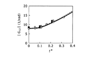
図3は、風洞実験と数値シミュレーションによって得られた上下正弦加振時の揚力係数のゲインを式(5)の空力モデルで予測した値と比較したものである。図4は、図3に対応して、風洞実験と数値シミュレーションによって得られた上下正弦加振時の揚力係数の位相を式(5)の空力モデルで予測した値と比較したものである。 FIG. 3 compares the gain of the lift coefficient at the time of vertical sine excitation obtained by the wind tunnel experiment and numerical simulation with the value predicted by the aerodynamic model of Equation (5). FIG. 4 corresponds to FIG. 3 and compares the phase of the lift coefficient during vertical sine excitation obtained by wind tunnel experiments and numerical simulation with the value predicted by the aerodynamic model of equation (5).
ここで上下正弦加振時の揚力係数のゲインと位相とは、ピッチ正弦加振時のときに説明したのと同様に、入力変数を上下変位zとし、出力をΔCZとして、式(5)の2行2列の行列の左上の式について周波数伝達関数を求め、そのゲインと位相ずれの周波数応答を計算することで得ることができる。また、上記のように、このようにして得られる予測値と、風洞実験または数値シミュレーションから得られる値との比較によって、従来技術のモデルの正確性を評価できる。 Here, the gain and phase of the lift coefficient at the time of vertical sine vibration are the same as those explained at the time of pitch sine vibration, the input variable is vertical displacement z, the output is ΔC Z , and the equation (5) The frequency transfer function is obtained for the upper left expression of the 2-by-2 matrix, and the frequency response of the gain and phase shift can be calculated. Further, as described above, the accuracy of the model of the prior art can be evaluated by comparing the predicted value obtained in this way with the value obtained from the wind tunnel experiment or numerical simulation.
図3は、横軸に無次元周波数f*をとり、縦軸に上下正弦加振時の揚力係数のゲイン
ここで特に図4に示されるように、風洞実験および数値シミュレーションでは、上下変位に対する揚力係数における位相遅れが45度付近で飽和する挙動を示すのに対し、式(5)のモデルによる予測値では位相遅れが70度以上に達する。このように、式(5)のモデルでは、上下変位に対する揚力係数の位相特性を正しく把握できていないことが分かる。ここでは、式(5)の2行2列の行列の左上の式に特性半径Rが含まれていないことから、この原因は、後述するように、式(5)のモデルに加速度項がないことに起因するものと考えられる。 In particular, as shown in FIG. 4, in the wind tunnel experiment and the numerical simulation, the phase lag in the lift coefficient with respect to the vertical displacement shows a behavior that saturates around 45 degrees, whereas the predicted value based on the model of Equation (5) The phase lag reaches 70 degrees or more. Thus, it can be seen that in the model of equation (5), the phase characteristic of the lift coefficient with respect to the vertical displacement is not correctly grasped. Here, since the characteristic radius R is not included in the upper left expression of the matrix of 2 rows and 2 columns of Expression (5), the cause is that there is no acceleration term in the model of Expression (5), as will be described later. This is thought to be caused by this.
以上で特許文献2における式(5)の説明を行ったので、次に動的空力モデルを適用できる車両空気力算出装置の内容について説明する。図5は、動的空力モデルを適用できる車両空気力算出装置10の構成を説明する図である。
The expression (5) in Patent Document 2 has been described above. Next, the contents of the vehicle aerodynamic force calculation apparatus to which the dynamic aerodynamic model can be applied will be described. FIG. 5 is a diagram illustrating the configuration of the vehicle aerodynamic
車両空気力算出装置10は、演算処理を実行するCPU12と、キーボード等の入力部14と、ディスプレイ等の出力部16と、ハードディスク等の記憶部18を含んで構成される。これらの各要素は内部バスによって相互に接続される。かかる車両空気力算出装置10としては、演算処理に適したコンピュータで構成することができる。
The vehicle aerodynamic
記憶部18は、車両空気力算出に用いられるプログラム等を格納する記憶装置で、ここでは特に、風洞実験および数値シミュレーションによって得られた各種のデータ等が車両に対応付けられて記憶される。記憶される各種のデータの例としては、式(1)から式((4)で示される基準姿勢における空力係数、空力微係数である空力係数勾配、加速度項に関する加速度項係数のデータ20、付加質量係数のデータ、特性半径のデータ22等が含まれる。加速度項係数のデータ20、特性半径のデータ22を得るための手順の詳細については後述する。
The
CPU12は、上記のρ,U,A,L,R等必要な諸条件を解析条件として取得する条件取得処理部24と、車両に作用する空気力の動的空力モデルのモデル化を行うモデル化処理部26と、車両に作用する空気力について、上下力とピッチングモーメントを外力とする場合には揚力係数変動成分ΔCZとピッチングモーメント係数変動成分ΔCMYをそれぞれ算出し、横力とヨーイングモーメントを外力とする場合には、横力係数変動成分ΔCYとヨーイングモーメント係数変動成分ΔCMZをそれぞれ算出する変動成分算出処理部28と、算出された変動成分に基づいて、車両に作用する外力をそれぞれ算出する作用量算出処理部30を含んで構成される。
The
なお、図5には、車両空気力算出装置10を拡張して車両運動解析装置とする場合に、CPU12が有する機能として、運動方程式解析処理部32が破線枠で示されている。この運動方程式解析処理部32は、車両空気力算出装置10で算出された空気力による外力を車両の運動方程式に組み込み、車両の運動解析を実行する処理機能を有する。このように、車両空気力算出装置10に、適当な演算処理機能等を付加することで車両運動解析装置として拡張できる。
In FIG. 5, when the vehicle aerodynamic
また、車両空気力算出装置10を拡張して車両サスペンション制御装置とすることもできる。この場合には、図5には図示されていないが、CPU12が有する機能として、車両サスペンション制御処理部が設けられる。ここで車両サスペンション制御処理部は、車両空気力算出装置10で算出された外力を車両に作用する外力として、車両の運動方程式に組み込み、空気力が作用しないときの運動方程式との比較に基いて車両のサスペンション要素の制御を行う処理機能を有する。このように、車両空気力算出装置10に、適当な演算処理機能等を付加することで車両サスペンション制御装置として拡張できる。
Further, the vehicle aerodynamic
かかる機能はソフトウェアによって実現され、具体的には、対応する車両空気力算出プログラムを実行することで実現できる。なお、上記の機能の一部をハードウェアで実現するものとしてもよい。CPU12の各処理部の機能は、この車両空気力算出プログラムをハードウェアとしてのCPU12が実行することで実現される。その意味で、CPU12の各処理部の機能は、車両空気力算出プログラムの各処理手順を示すものである。
Such a function is realized by software, and specifically, can be realized by executing a corresponding vehicle aerodynamic force calculation program. Note that part of the above functions may be realized by hardware. The function of each processing unit of the
以下に上記構成の作用について詳細に説明する。最初に、CPU12において用いられる車両に作用する空気力についての動的空力モデルを説明し、次に記憶部18に格納される加速度項係数と特性半径について、それらを風洞実験等から求める手順を説明する。そして、車両の運動解析の手順を説明し、その結果として動的空力モデルを用いることの効果について説明する。
The operation of the above configuration will be described in detail below. First, the dynamic aerodynamic model for the aerodynamic force acting on the vehicle used in the
車両の運動方程式に組み込む外力としての車両に作用する空気力は、よく知られた式(8),(9)を用いる。
ここで、車両に作用する空気力のうち上下力FZが式(8)で示され、ピッチングモーメントMYが式(9)で示される。 Here, among the aerodynamic forces acting on the vehicle, the vertical force F Z is expressed by the equation (8), and the pitching moment M Y is expressed by the equation (9).
式(8)におけるΔCZは、式(1)で説明した車両の基準姿勢における基準揚力係数からの変動成分である揚力係数変動成分である。式(9)におけるΔCMYは、式(2)で説明した車両の基準姿勢における基準ピッチングモーメント係数からの変動成分であるピッチングモーメント係数変動成分である。 ΔC Z in the equation (8) is a lift coefficient fluctuation component that is a fluctuation component from the reference lift coefficient in the vehicle reference posture described in the expression (1). ΔC MY in the equation (9) is a pitching moment coefficient variation component that is a variation component from the reference pitching moment coefficient in the vehicle reference posture described in the equation (2).
車両空気力算出装置10では、入力変数である上下変位z、ピッチ変位角θと、出力であるΔCZ、ΔCMYとの関係を、式(5)で説明した準定常空力モデルに付加質量に起因する加速度項を付与した線形システムとして、式(10)で示されるモデル化を行う。
なお、式(10)に代えて、このような速度項の表現も抗力係数
ここで、s2の項が付加質量に起因する加速度項である。付加質量とは、流体力学で用いられる概念で、この場合、車両の加速度運動に伴って周囲の流体が移動することによる見かけ上の質量増加分である。周囲の流体は、ここでは空気である。 Here, the term of s 2 is an acceleration term due to the added mass. The added mass is a concept used in hydrodynamics, and in this case, an added mass is an apparent increase in mass due to the movement of surrounding fluid with the acceleration motion of the vehicle. The surrounding fluid here is air.
次に、式(10)における各係数の算出手順を説明する。各係数は、実車または車両模型を用いた風洞実験あるいは数値シミュレーションによって算出が行われる。実際の各係数の算出には該当する車両あるいは車両模型を使用する必要があるが、以下では、単純化された車両模型の例としてアーメド(Ahmed)模型として知られる図6の3次元模型を用いて解析等を進めた。アーメド模型は、傾斜背面を有する直方体形状で、前面側の4辺に適当な丸みを設けた模型である。ここで、図6には、各式で用いられるX,Y,Zの方向が示されている。このように、X方向は車両の走行方向で、Y方向は車両の車幅方向で、Z方向が車両の上下方向である。 Next, the calculation procedure of each coefficient in Expression (10) will be described. Each coefficient is calculated by a wind tunnel experiment or a numerical simulation using an actual vehicle or a vehicle model. The actual vehicle or vehicle model needs to be used for the actual calculation of each coefficient. In the following, a three-dimensional model shown in FIG. 6 known as an Ahmed model is used as an example of a simplified vehicle model. The analysis was advanced. The Ahmed model is a rectangular parallelepiped shape having an inclined back surface, and is provided with appropriate roundness on four sides on the front surface side. Here, FIG. 6 shows the X, Y, and Z directions used in each equation. Thus, the X direction is the vehicle traveling direction, the Y direction is the vehicle width direction, and the Z direction is the vertical direction of the vehicle.
式(10)における各係数のうち、zに対するCZの変化勾配、θに対するCZの変化勾配、zに対するCMYの変化勾配、θに対するCMYの変化勾配は、静的空力係数勾配と呼ばれる。これらの算出は、まず、風洞実験あるいは数値シミュレーションによって、上下変位およびピッチ変位角について基準姿勢まわりの予め定めた所定の範囲において複数の静的な揚力係数と静的なピッチングモーメント係数を取得する。所定の範囲としては、上記のアーメド模型を用いた場合に、例えば、上下変位について±8mm、ピッチ変位角について±0.878°等とすることができる。 Of the coefficients in equation (10), the gradient of change C Z for z, gradient of change C Z relative theta, the gradient of change C MY for z, the slope of change C MY for theta is called static aerodynamic coefficient gradient . In these calculations, first, a plurality of static lift coefficients and static pitching moment coefficients are acquired in a predetermined range around the reference posture with respect to the vertical displacement and the pitch displacement angle by a wind tunnel experiment or numerical simulation. As the predetermined range, when the above-mentioned Ahmed model is used, for example, the vertical displacement can be ± 8 mm, the pitch displacement angle can be ± 0.878 °, and the like.
そして、上下変位の所定の範囲で得られた複数の静的揚力係数の上下変位についての勾配を算出してzに対するCZの変化勾配を求め、ピッチ角の所定の範囲で得られた複数の静的揚力係数のピッチ角についての勾配を算出してθに対するCZの変化勾配を求める。同様に、上下変位の所定の範囲で得られた複数の静的ピッチングモーメントの上下変位についての勾配を算出してzに対するCMYの変化勾配を求め、ピッチ角の所定の範囲で得られた静的ピッチングモーメントのピッチ角についての勾配を算出してθに対するCMYの変化勾配を求める。 Then, the gradient of the vertical displacement of the plurality of static lift coefficients obtained in the predetermined range of the vertical displacement is calculated to obtain the change gradient of C Z with respect to z, and the plurality of the gradient angles obtained in the predetermined range of the pitch angle are obtained. The gradient of the static lift coefficient with respect to the pitch angle is calculated to determine the change gradient of C Z with respect to θ. Similarly, determine the change in slope of the C MY for z by calculating the gradient of the vertical displacement of the plurality of static pitching moment obtained in a predetermined range of vertical displacement, obtained within a predetermined range of the pitch angle static Request C MY the change gradient for θ to calculate the gradient of the pitch angle of the pitching moment.
このようにして算出された静的空力係数勾配の例を式(13)に示す。
式(10)における各係数のうち、特性半径RP12,RP22、加速度項係数αP11,αP12,αP21,αP22は、次のようにして求める。すなわち、風洞実験あるいは数値シミュレーションによって、上下変位およびピッチ変位角について基準姿勢まわりの予め定めた所定の範囲で車両模型を加振する。所定の範囲の加振としては、例えば、上記のアーメド模型を用いた場合に、上下変位について±8mmの正弦加振、ピッチ変位角について±0.878°の正弦加振等とすることができる。そして、この加振に対する揚力係数とピッチングモーメント係数とについて、時系列的な信号を同時に対応付けながら取得する。 Among the coefficients in the equation (10), the characteristic radii R P12 and R P22 and the acceleration term coefficients α P11 , α P12 , α P21 and α P22 are obtained as follows. That is, the vehicle model is vibrated in a predetermined range around the reference posture with respect to the vertical displacement and the pitch displacement angle by a wind tunnel experiment or numerical simulation. As the predetermined range of vibration, for example, when the above-mentioned Ahmed model is used, the vertical displacement may be ± 8 mm sine vibration, the pitch displacement angle may be ± 0.878 ° sine vibration, and the like. . Then, the lift coefficient and the pitching moment coefficient with respect to this excitation are obtained while simultaneously associating time-series signals.
例えば、式(10)において、上下加振に対する揚力係数変動成分のモデルを抜き出すと式(14)となる。
そこで、車両模型から上下変位zを取得できるときはこの上下変位zから数値微分によって姿勢変化速度dz/dtと姿勢変化加速度d2z/dt2の時系列信号を求める。あるいは、逆に車両模型の加速度が取得できるときは、この加速度から数値積分によって姿勢変化速度dz/dtと上下変位zの時系列信号を求めるものとしてもよい。 Therefore, when the vertical displacement z can be obtained from the vehicle model, time series signals of the posture change speed dz / dt and the posture change acceleration d 2 z / dt 2 are obtained by numerical differentiation from the vertical displacement z. Alternatively, when the acceleration of the vehicle model can be acquired, the time series signals of the attitude change speed dz / dt and the vertical displacement z may be obtained from this acceleration by numerical integration.
ここで、式(14)のAとUは既知であり、静的空力係数勾配は、上記の式(13)に示されるように別途算出できるので、入力データとして、z,dz/dt,d2z/dt2と、出力データとしてのΔCZを与え、一般的に用いられている最適近似法としての曲線近似法あるいはデータ近似法を用いて、式(14)の方程式に最も近似するように係数αP11を同定する。このようにして加速度項係数αP11を求めることができる。 Here, A and U in Equation (14) are known, and the static aerodynamic coefficient gradient can be separately calculated as shown in Equation (13) above, so that z, dz / dt, d are used as input data. 2 z / dt 2 and ΔC Z as output data are given, and a curve approximation method or a data approximation method as an optimum approximation method that is generally used is used to approximate the equation (14) most closely. The coefficient α P11 is identified. In this way, the acceleration term coefficient α P11 can be obtained.
同様にして、ピッチ加振に対する揚力係数から、加速度項係数αP12と特性半径RP12を得ることができる。また、上下加振に対するピッチングモーメントから、加速度項係数αP21を求められる。また、ピッチ加振に対するピッチングモーメントから、加速度項係数αP22と特性半径RP22を求めることができる。 Similarly, the acceleration term coefficient α P12 and the characteristic radius R P12 can be obtained from the lift coefficient for pitch excitation. Further, the acceleration term coefficient α P21 can be obtained from the pitching moment with respect to the vertical vibration. Further, the acceleration term coefficient α P22 and the characteristic radius R P22 can be obtained from the pitching moment with respect to the pitch excitation.
このように、ある加振周波数での上下加振とピッチ加振に対して風洞実験あるいは数値シミュレーションをそれぞれ最低1回行うことで、式(10)におけるすべての未知数を求めることができる。 In this way, all unknowns in Equation (10) can be obtained by performing at least one wind tunnel experiment or numerical simulation for vertical and pitch excitations at a certain excitation frequency.
また、別の実施形態として、ある加振周波数でのピッチ加振に対して特性半径RP12,RP22を同定し、別のある加振周波数でのピッチ加振に対して加速度項係数αP12,αP22を同定するものとしてもよい。さらに別の実施形態として、複数の加振周波数で得られたゲイン、あるいは位相に対して、式(10)から求まる周波数応答のゲイン、あるいは位相をフィッティングして加速度項係数および特性半径を求めてもよい。 As another embodiment, the characteristic radii R P12 and R P22 are identified for pitch excitation at a certain excitation frequency, and the acceleration term coefficient α P12 for pitch excitation at another excitation frequency. , Α P22 may be identified. As yet another embodiment, an acceleration term coefficient and a characteristic radius are obtained by fitting the gain or phase obtained from Equation (10) to the gain or phase obtained at a plurality of excitation frequencies. Also good.
上下加振の振幅8mm、ピッチ加振の振幅角0.878°、そのときの加振周波数をともに8Hzとして、これら2つのケースの結果を用いて同定して得られた各特性半径、各加速度項係数の例を式(15)に示す。
このようにして得られた各加速度項係数は、加速度項係数のデータ20として、各特性半径は、特性半径のデータ22として、記憶部18に記憶される。
Each acceleration term coefficient thus obtained is stored in the
以上で、記憶部18に格納される加速度項係数と特性半径について、それらを風洞実験等から求める手順を説明したので、次に、車両の空気力算出の手順を説明する。
The procedure for obtaining the acceleration term coefficient and the characteristic radius stored in the
車両空気力算出装置10が起動すると、記憶部18に格納されている車両空気力算出プログラムが立ち上がる。そこで、ユーザは、入力部14から解析条件として、空気密度ρと、車両速度Uと、車両の前面投影面積Aと、車両の代表長さLとを入力する。入力された各条件は、CPU12の条件取得処理部24の機能によって、解析条件として取得される(解析条件取得工程)。
When the vehicle aerodynamic
解析条件取得としては、これ以外の方法によることもできる。例えば、車両速度Uは車両運動解析プログラムからの出力として逐次更新するものとしてもよい。また、外部接続インターフェースを介して得られるデータを解析条件として取得するものとしてもよい。例えば、実車走行時のオンライン計測データを取得し、これを解析条件として取得するものとできる。また、記憶部18に各種解析条件が記憶されていて、それらを読み出して取得するものとすることもできる。各種解析条件のうち、一部が入力部14から取得され、一部が記憶部18から取得され、一部が外部インターフェースから取得される等のように複数の取得手段を用いることもできる。
The analysis conditions can be acquired by other methods. For example, the vehicle speed U may be sequentially updated as an output from the vehicle motion analysis program. Moreover, it is good also as what acquires the data obtained via an external connection interface as analysis conditions. For example, it is possible to acquire online measurement data during actual vehicle travel and acquire this as analysis conditions. In addition, various analysis conditions are stored in the
そして、記憶部18に記憶されている加速度項係数のデータ20と特性半径のデータ22が読み出されて取得され、これを用いて式(10)の線形モデルのモデル化が行われる(モデル化工程)。この工程はCPU12のモデル化処理部26の機能によって実行される。
Then, the acceleration
次に、取得された解析条件と、モデル化された線形モデルとを用い、式(10)に基づいて、揚力係数変動成分ΔCZとピッチングモーメント係数変動成分ΔCMYがそれぞれ算出される(変動成分算出工程)。この工程は、CPU12の変動成分算出処理部28の機能によって実行される。
Next, using the obtained analysis condition and the modeled linear model, the lift coefficient variation component ΔC Z and the pitching moment coefficient variation component ΔC MY are calculated based on the equation (10) (variation component). Calculation step). This process is executed by the function of the fluctuation component
そして、算出された揚力係数変動成分ΔCZとピッチングモーメント係数変動成分ΔCMYとを用い、空気力によって車両に作用する外力として、式(8)に基づいて上下力FZが算出され、式(9)に基づいてピッチングモーメントMYがそれぞれ算出される(作用量算出工程)。この工程は、CPU12の作用量算出処理部30の機能によって実行される。
Then, using the calculated lift coefficient variation component ΔC Z and the pitching moment coefficient variation component ΔC MY , the vertical force F Z is calculated based on the equation (8) as an external force acting on the vehicle by the aerodynamic force. The pitching moments M Y are respectively calculated based on 9) (action amount calculating step). This step is executed by the function of the action amount
このようにして、風洞実験等で得られた加速度項係数等を用いた動的空力モデルに基づき、車両に作用する外力としての空気力の算出が行われる。なお、算出された空気力の算出に基づいて車両の運動解析を進めるには、次に、算出された上下力FZとピッチングモーメントMYを車両に作用する外力として、車両の運動方程式に組み込み、車両の運動解析を実行する(運動方程式解析工程)。この工程は、図5に破線枠で示したCPU12の運動方程式解析処理部32の機能によって実行される。このように、車両空気力算出装置10を発展させて、車両に作用する空気力を考慮した車両の運動解析を適切に行うことができる。また、同様に、車両空気力算出装置10を発展させて、車両サスペンション制御を適切に行うこともできる。
In this way, aerodynamic force as an external force acting on the vehicle is calculated based on a dynamic aerodynamic model using an acceleration term coefficient or the like obtained in a wind tunnel experiment or the like. Incidentally, built in advance the motion analysis of the vehicle based on the calculation of the calculated air force, then, the vertical force F Z and pitching moment M Y calculated as an external force acting on the vehicle, the equation of motion of the vehicle The vehicle motion analysis is executed (motion equation analysis step). This step is executed by the function of the motion equation
次に、車両空気力算出装置10による効果を図7から図12を用いて説明する。図7と図8は、図1,2に対応するもので、風洞実験および数値シミュレーションによって得られたピッチ正弦加振時の揚力係数のゲインと位相を、上記の方法で算出した各加速度項係数等を用いて算出した式(10)の動的空力モデルの結果と比較したものである。図7の横軸、縦軸の内容は図1と同じ、図8の横軸、縦軸の内容は図2と同じである。白抜マークの風洞実験の結果、黒塗マークの数値シミュレーションの結果も図1,2と同じである。
Next, the effect of the vehicle aerodynamic
図7,8における破線が上記の方法で算出した各加速度項係数等を用いて算出した式(10)の動的空力モデルの結果である。実線は、式(10)において加速度項を含まないものとして算出した結果である。図7,8における実線が、図1,2と異なるのは、図1,2においては、特性半径が車両の半車長であるのに対し、図7,8における実線は、特性半径を風洞実験あるいは数値シミュレーションによって同定したものであることである。 The broken lines in FIGS. 7 and 8 are the results of the dynamic aerodynamic model of Expression (10) calculated using each acceleration term coefficient calculated by the above method. The solid line is the result of calculation in Equation (10) assuming that the acceleration term is not included. The solid line in FIGS. 7 and 8 is different from FIGS. 1 and 2 in that the characteristic radius is the half vehicle length of the vehicle in FIGS. 1 and 2, whereas the solid line in FIGS. It is identified by experiment or numerical simulation.
図7,8において、実線と破線とがあまり相違がないことから、ピッチ正弦加振時の揚力係数に対しては、加速度項の影響が少ないことが分かる。一方で、実線も破線も、風洞実験の結果と数値シミュレーションの結果とよく一致し、図1,2の結果と大きく異なるので、特性半径を風洞実験あるいは数値シミュレーションによって同定することがよいことが分かる。 7 and 8, since the solid line and the broken line are not so different, it can be seen that the influence of the acceleration term is small on the lift coefficient during pitch sine excitation. On the other hand, the solid line and the broken line both agree well with the results of the wind tunnel experiment and the numerical simulation, and are greatly different from the results of FIGS. 1 and 2, so it can be seen that the characteristic radius should be identified by the wind tunnel experiment or the numerical simulation. .
したがって、風洞実験あるいは数値シミュレーションによって同定された特性半径を用いることで、既存の準定常空力モデルでも、ピッチ加振時の揚力係数をより正確に表現できることになる。 Therefore, by using the characteristic radius identified by the wind tunnel experiment or numerical simulation, the lift coefficient at the time of pitch excitation can be expressed more accurately even in the existing quasi-stationary aerodynamic model.
図9と図10は、図3,4に対応するもので、風洞実験および数値シミュレーションによって得られた上下正弦加振時の揚力係数のゲインと位相を、上記の方法で算出した各加速度項係数等を用いて算出した式(10)の動的空力モデルの結果と比較したものである。図9の横軸、縦軸の内容は図3と同じ、図10の横軸、縦軸の内容は図4と同じである。白抜マークの風洞実験の結果、黒塗マークの数値シミュレーションの結果も図3,4と同じである。 FIGS. 9 and 10 correspond to FIGS. 3 and 4, and the gain and phase of the lift coefficient at the time of upper and lower sine excitation obtained by the wind tunnel experiment and numerical simulation are obtained by calculating each acceleration term coefficient by the above method. It compares with the result of the dynamic aerodynamic model of Formula (10) calculated using the above. The contents of the horizontal and vertical axes in FIG. 9 are the same as in FIG. 3, and the contents of the horizontal and vertical axes in FIG. 10 are the same as in FIG. As a result of the wind tunnel experiment of the white mark, the result of the numerical simulation of the black mark is the same as in FIGS.
図9,10における破線が上記の方法で算出した各加速度項係数等を用いて算出した式(10)の動的空力モデルの結果である。実線は、式(10)において加速度項を含まないものとして算出した結果である。つまり、実線は、図3,4で説明した準定常空力モデルによる結果と同じである。 The broken lines in FIGS. 9 and 10 are the results of the dynamic aerodynamic model of Expression (10) calculated using each acceleration term coefficient calculated by the above method. The solid line is the result of calculation in Equation (10) assuming that the acceleration term is not included. That is, the solid line is the same as the result by the quasi-stationary aerodynamic model described with reference to FIGS.
図9,10に示されるように、風洞実験等の結果が破線とよく合い、実線と大きく異なる。このことから、無次元周波数f*が0.05よりも大きい範囲において、付加質量に起因する加速度項が無視できないことが分かる。例えば、時速100km/hで走行する全長4.5mの車両が2Hzで振動する場合の無次元周波数f*は0.324となる。車速が下がれば無次元周波数f*はさらに大きくなる。このことから、一般的な車両の走行環境において、その車両の運動は、付加質量の影響が無視できず、動的空力モデルを適用する必要があることが分かる。 As shown in FIGS. 9 and 10, the results of the wind tunnel experiment and the like match well with the broken line and are greatly different from the solid line. From this, it can be seen that in the range where the dimensionless frequency f * is larger than 0.05, the acceleration term due to the added mass cannot be ignored. For example, the dimensionless frequency f * when a vehicle with a total length of 4.5 m traveling at 100 km / h vibrates at 2 Hz is 0.324. As the vehicle speed decreases, the dimensionless frequency f * further increases. From this, it can be understood that in a general vehicle traveling environment, the influence of the added mass cannot be ignored for the movement of the vehicle, and it is necessary to apply a dynamic aerodynamic model.
図11,12は、上下変位zに対する揚力係数CZのリサージュ曲線を風洞実験の結果と、各空力モデルによる計算結果とで比較したものである。図11は、従来技術の準定常空力モデルによる計算結果との比較、図12は、動的空力モデルによる計算結果との比較である。実験結果において丸マークは加振周波数が2Hz、Xマークは加振周波数が4Hz、△マークは加振周波数が8Hzの場合である。 11 and 12 compare the Lissajous curves of the lift coefficient C Z with respect to the vertical displacement z between the results of the wind tunnel experiment and the calculation results of each aerodynamic model. FIG. 11 is a comparison with the calculation result by the quasi-stationary aerodynamic model of the prior art, and FIG. 12 is a comparison with the calculation result by the dynamic aerodynamic model. In the experimental results, the circle mark is the excitation frequency of 2 Hz, the X mark is the excitation frequency of 4 Hz, and the Δ mark is the excitation frequency of 8 Hz.
図11,12を比較すると、準定常空力モデルの計算結果は、加振周波数の増加に伴うリサージュ曲線の傾きの増加、すなわち空気ばね定数の増加を適切に表現できないが、付加質量に起因する加速度項を考慮した動的空力モデルではその特性をよく表現できることが分かる。 Comparing FIGS. 11 and 12, the calculation result of the quasi-stationary aerodynamic model cannot appropriately express the increase in the slope of the Lissajous curve accompanying the increase in the excitation frequency, that is, the increase in the air spring constant, but the acceleration caused by the added mass It can be seen that the dynamic aerodynamic model considering the terms can express its characteristics well.
ここで、付加質量を、その物体によって排除される流体の質量で無次元化した値である付加質量係数cP11を用いることで、加速度項係数αP11は式(16)で表すことができる。
ここで、Vは車両体積である。車両模型を用いている場合は車両模型体積である。 Here, V is a vehicle volume. When a vehicle model is used, it is a vehicle model volume.
この類推から、他の加速度項係数αP12,αP21,αP22も同様に無次元の係数cP12,cP21,cP22を用いて記述することができる。例えば、式(17)のように示すことができる。
あるいは、加速度項係数αP12,αP21を、長さの次元を有する係数aP12,aP21を用いて、例えば式(18)のように示すこともできる。
数値シミュレーションでは、実車走行条件の下での計算結果を用いて加速度項係数αP11,αP12,αP21,αP22を上記のような手順で同定することができるが、実車走行条件での試験が困難なことがある風洞実験では、縮尺模型を用いた実験結果から、上記無次元の係数cP11,cP12,cP21,cP22を同定してもよい。すなわち、無次元の係数cP11,cP12,cP21,cP22は、車両形状、地面からの距離、車速、振動振幅、振動数等に依存するが、無次元周波数の範囲が同等であり、模型形状、模型と地面との間の距離、加振振幅が実車スケールとほぼ相似の関係にある場合には、縮尺模型によって得られた値を実車スケールの問題に適用することが可能だからである。 In the numerical simulation, the acceleration term coefficients α P11 , α P12 , α P21 , α P22 can be identified by the procedure as described above using the calculation results under the actual vehicle driving conditions. In a wind tunnel experiment that may be difficult, the dimensionless coefficients c P11 , c P12 , c P21 , and c P22 may be identified from the experimental results using a scale model. That is, the dimensionless coefficients c P11 , c P12 , c P21 , and c P22 depend on the vehicle shape, the distance from the ground, the vehicle speed, the vibration amplitude, the frequency, and the like, but have the same dimensionless frequency range, This is because when the model shape, the distance between the model and the ground, and the excitation amplitude are almost similar to the actual vehicle scale, the values obtained by the scale model can be applied to the actual vehicle scale problem. .
なお、式(10)の行列における非対角成分の加速度項、つまり、ピッチ加振に対する揚力係数の加速度項、上下加振に対するピッチングモーメント係数の加速度項は無視しても差し支えない。すなわち、αP12=αP21=0とできる。 Note that the acceleration term of the non-diagonal component in the matrix of equation (10), that is, the acceleration term of the lift coefficient for pitch excitation and the acceleration term of the pitching moment coefficient for vertical excitation can be ignored. That is, α P12 = α P21 = 0.
一方、対角成分であるαP11とαP22の式に含まれてくるVに空気密度ρを乗じたもの、および式(17)で示される(x2+z2)のdVに対する積分項に空気密度ρを乗じたものは、それぞれ模型が排除した流体である空気の質量と、その慣性モーメントに相当し、これらは汎用的なCADソフト等で容易に算出することができる。このようにして算出された排除空気質量に関する付加質量係数cP11、および排除空気の慣性モーメントに関する無次元の係数である付加慣性モーメント係数cP22を式(19)に示す。
なお、αP22も全体としての影響が小さいので、場合によっては省略して無視することができる。 Note that α P22 also has a small influence as a whole, and can be omitted and ignored in some cases.
例えば、無限静止流体中の2次元円柱が並進運動する場合の付加質量係数は1であるが、物体に接近して固定壁が存在するときは壁面に直角な方向の運動に対する付加質量係数が増大することが知られている。車両が道路上を走行する場合は、この固定壁が存在するときに類似し、これらのことから、式(19)のcP11の値が妥当なものであることが分かる。 For example, the additional mass coefficient is 1 when a two-dimensional cylinder in an infinite static fluid moves in translation. However, when a fixed wall exists close to an object, the additional mass coefficient for movement in a direction perpendicular to the wall surface increases. It is known to do. When the vehicle travels on the road, it is similar to the case where the fixed wall exists, and from these, it can be seen that the value of cP11 in the equation (19) is appropriate.
上記では、車両の縦運動に限った実験あるいは数値シミュレーションを行っているが、同様な考えを車両の横運動に対しても拡張できる。すなわち、車両の運動方程式に組み込む外力として、空気力による横力FYを式(20)、ヨーイングモーメントMZを式(21)のように表現できる。
ここで、ΔCYは、式(3)で示される車両の基準姿勢における基準横力係数からの変動成分である横力係数変動成分である。ΔCMZは、式(4)で示される車両の基準姿勢における基準ヨーイングモーメント係数からの変動成分であるヨーイングモーメント係数変動成分である。 Here, ΔC Y is a lateral force coefficient fluctuation component that is a fluctuation component from the reference lateral force coefficient in the reference posture of the vehicle represented by Expression (3). ΔC MZ is a yawing moment coefficient fluctuation component that is a fluctuation component from the reference yawing moment coefficient in the reference posture of the vehicle represented by the equation (4).
ここで、入力変数である横変位y、ヨー変位角βと、出力であるΔCY、ΔCMZとの関係を、式(10)と同様に、付加質量に起因する加速度項を付与した線形システムとして、式(22)で示されるモデル化を行うことができる。
ここで、s2の項が付加質量に起因する加速度項である。なお、式(12)に関連して説明したのと同様に、式(22)に代えて、基準姿勢における抗力係数を用いた式(23)で示されるモデル化を行うものとしてもよい。
なお、式(10)の行列における非対角成分の加速度項等に関連して説明したのと同様に、ここでも、αY12,αY21,αY22を無視することが可能である。また、上下加振時に比べればαY11の影響も小さいものと考えられる。 Note that α Y12 , α Y21 , and α Y22 can be ignored here as well, as described in relation to the acceleration term of the off-diagonal component in the matrix of equation (10). In addition, the influence of α Y11 is considered to be small as compared with the case of vertical vibration.
このように、風洞実験等で同定した加速度項係数等を用いて構築される式(10),(22)の動的空力モデルを用いて、姿勢変化を伴う車両に作用する動的な空気力の算出を適切に行うことができる。また、これを発展させ、算出された空気力に基づいて、車両の運動解析を行うことができ、さらに車両のサスペンション制御を行うことができる。なお、上下力、ピッチングモーメント、横力、ヨーイングモーメントの全てを用いて運動解析を行ってもよい。 As described above, the dynamic aerodynamic force acting on the vehicle with the attitude change is obtained by using the dynamic aerodynamic model of the equations (10) and (22) constructed using the acceleration term coefficient identified by the wind tunnel experiment or the like. Can be appropriately calculated. Further, by developing this, it is possible to perform vehicle motion analysis based on the calculated aerodynamic force, and to perform vehicle suspension control. The motion analysis may be performed using all of the vertical force, pitching moment, lateral force, and yawing moment.
車両空気力算出を車両のサスペンション制御に応用するには、次のようにすることができる。すなわち、動的空力モデルに基づく空気力を車両に作用する外力として、並進運動の運動方程式、回転運動の運動方程式に組み込み、空気力が作用しないときの運動方程式と等価になるように、車両のサスペンションの見かけのばね定数、減衰定数を算出する。そして、算出された見かけのばね定数と減衰定数と、実際のばね定数と減衰定数との差を、空気力の作用による見かけのばね定数の変化量、見かけの減衰定数の変化量とすることができる。なお、正弦振動を仮定することで、付加質量の影響を見かけのばね定数に組み込むことができる。これにより、空気力が作用する車両について、サスペンション制御を適切に行う制御装置を構成することができる。 Application of vehicle aerodynamic force calculation to vehicle suspension control can be performed as follows. In other words, the aerodynamic force based on the dynamic aerodynamic model is incorporated into the translational motion equation and the rotational motion equation as an external force acting on the vehicle, and is equivalent to the motion equation when the aerodynamic force does not act. Calculate the apparent spring constant and damping constant of the suspension. Then, the difference between the calculated apparent spring constant and damping constant and the actual spring constant and damping constant can be used as the amount of change in the apparent spring constant and the amount of change in the apparent damping constant due to the action of aerodynamic force. it can. Note that by assuming sinusoidal vibration, the effect of additional mass can be incorporated into the apparent spring constant. Thereby, the control apparatus which performs suspension control appropriately about the vehicle on which an aerodynamic force acts can be comprised.
本発明に係る車両空気力算出装置は、走行する車両に空気力が作用するときの運動状態を解析する装置に利用され、また、空気力を考慮した車両サスペンション制御装置に利用できる。車両サスペンション制御装置においては、空気力の影響を考慮したサスペンションのばね定数設定、減衰定数設定に利用できる。 The vehicle aerodynamic force calculation apparatus according to the present invention can be used for an apparatus that analyzes a motion state when an aerodynamic force acts on a traveling vehicle, and can be used for a vehicle suspension control apparatus that takes aerodynamic forces into consideration. The vehicle suspension control device can be used for setting a spring constant and a damping constant of a suspension in consideration of the influence of aerodynamic forces.
10 車両空気力算出装置、12 CPU、14 入力部、16 出力部、18 記憶部、20 加速度項係数データ、22 特性半径データ、24 条件取得処理部、26 モデル化処理部、28 変動成分算出処理部、30 作用量算出処理部、32 運動方程式解析処理部。
DESCRIPTION OF
Claims (18)
車両の基準姿勢における基準揚力係数からの変動成分である揚力係数変動成分をΔCZとし、車両の基準姿勢における基準ピッチングモーメント係数からの変動成分であるピッチングモーメント係数変動成分をΔCMYとして、揚力係数変動成分ΔCZとピッチングモーメント係数変動成分ΔCMYのそれぞれを、上下変位zとピッチ変位角θを入力変数として、各入力変数の2階微分までの項による線形モデルとしてモデル化するモデル化手段と、
条件取得手段によって取得した条件と、モデル化された線形モデルとに基づいて、揚力係数変動成分ΔCZとピッチングモーメント係数変動成分ΔCMYをそれぞれ算出する変動成分算出手段と、
算出された揚力係数変動成分ΔCZとピッチングモーメント係数変動成分ΔCMYとに基づいて、車両に作用する上下力とピッチングモーメントをそれぞれ算出する作用量算出手段と、
を備え、
モデル化手段は、2階微分項として、少なくとも上下変位zを入力変数としたときの揚力係数変動成分ΔCZに関する加速度項を有する線形モデルとしてモデル化することを特徴とする車両空気力算出装置。 Condition acquisition means for acquiring an air density ρ, a vehicle speed U, a front projection area A of the vehicle, a representative length L of the vehicle, and a characteristic radius R;
The lift coefficient fluctuation component, which is a fluctuation component from the reference lift coefficient in the vehicle's reference attitude, is ΔC Z, and the pitching moment coefficient fluctuation component, which is the fluctuation component from the reference pitching moment coefficient, in the vehicle's reference attitude is ΔC MY , the lift coefficient Modeling means for modeling the fluctuation component ΔC Z and the pitching moment coefficient fluctuation component ΔC MY as linear models with terms up to the second derivative of each input variable, with the vertical displacement z and the pitch displacement angle θ as input variables; ,
Fluctuation component calculation means for calculating the lift coefficient fluctuation component ΔC Z and the pitching moment coefficient fluctuation component ΔC MY based on the condition acquired by the condition acquisition means and the modeled linear model,
Action amount calculating means for calculating the vertical force and the pitching moment acting on the vehicle based on the calculated lift coefficient fluctuation component ΔC Z and the pitching moment coefficient fluctuation component ΔC MY ,
With
The vehicle aerodynamic force calculation device characterized in that the modeling means models as a linear model having an acceleration term related to a lift coefficient fluctuation component ΔC Z when the vertical displacement z is at least an input variable as a second-order differential term.
車両の基準姿勢における基準横力係数からの変動成分である横力係数変動成分をΔCYとし、車両の基準姿勢における基準ヨーイングモーメント係数からの変動成分であるヨーイングモーメント係数変動成分をΔCMZとして、横力係数変動成分ΔCYとヨーイングモーメント係数変動成分ΔCMZのそれぞれを、横変位yとヨー変位角βを入力変数として、各入力変数の2階微分までの項による線形モデルとしてモデル化するモデル化手段と、
条件取得手段によって取得した条件と、モデル化された線形モデルとに基づいて、横力係数変動成分ΔCYとヨーイングモーメント係数変動成分ΔCMZをそれぞれ算出する変動成分算出手段と、
算出された横力係数変動成分ΔCYとヨーイングモーメント係数変動成分ΔCMZとに基づいて、車両に作用する横力とヨーイングモーメントをそれぞれ算出する作用量算出手段と、
を備え、
モデル化手段は、2階微分項として、少なくとも横変位yを入力変数としたときの横力係数変動成分ΔCYに関する加速度項を有する線形モデルとしてモデル化することを特徴とする車両空気力算出装置。 Condition acquisition means for acquiring an air density ρ, a vehicle speed U, a front projection area A of the vehicle, a representative length L of the vehicle, and a characteristic radius R;
A lateral force coefficient fluctuation component that is a fluctuation component from the reference lateral force coefficient in the vehicle's reference attitude is ΔC Y, and a yawing moment coefficient fluctuation component that is a fluctuation component from the reference yawing moment coefficient in the vehicle's reference attitude is ΔC MZ , A model that models the lateral force coefficient fluctuation component ΔC Y and yaw moment coefficient fluctuation component ΔC MZ as linear models with terms up to the second derivative of each input variable, with the lateral displacement y and yaw displacement angle β as input variables. And
And conditions acquired by the condition acquisition unit, based on the modeled linear model, and the fluctuation component calculating means for calculating respective lateral force coefficient variation component [Delta] C Y and yawing moment coefficient variation component [Delta] C MZ,
Action amount calculating means for calculating the lateral force and yawing moment acting on the vehicle based on the calculated lateral force coefficient fluctuation component ΔC Y and yawing moment coefficient fluctuation component ΔC MZ ,
With
Modeling means, as second-order differential term, the vehicle air force calculating device, characterized in that the modeled as a linear model having an acceleration section in the lateral force coefficient variation component [Delta] C Y when an input variable at least lateral displacement y .
線形モデル化されたモデルにおける加速度項の係数を実車あるいは模型を用いた風洞実験または数値シミュレーションに基づいて取得する加速度項係数取得手段を備え、
モデル化手段は、取得された加速度項係数を用いて線形モデル化を行うことを特徴とする車両空気力算出装置。 In the vehicle aerodynamic force calculation device according to claim 1 or 2,
Acceleration term coefficient acquisition means for acquiring a coefficient of acceleration term in a linear model based on a wind tunnel experiment or numerical simulation using an actual vehicle or a model,
The vehicle aerodynamic force calculation apparatus characterized in that the modeling means performs linear modeling using the acquired acceleration term coefficient.
条件取得手段はさらに車両の代表体積Vを取得し、
上下変位zを入力変数としたときの揚力係数変動成分ΔCZの加速度項の効果を車両が加速度運動をする際に周囲の空気から受ける付加質量力であると考え、その付加質量を車両によって排除される空気の質量で無次元化した値である付加質量係数について、実車あるいは模型を用いた風洞実験または数値シミュレーションまたは文献値に基いて取得する付加質量係数取得手段を備え、
モデル化手段は、加速度項係数を、付加質量係数と車両の代表体積Vとの積として扱うことを特徴とする車両空気力算出装置。 In the vehicle aerodynamic force calculation device according to claim 1,
The condition acquisition means further acquires the representative volume V of the vehicle,
The effect of the acceleration term of the lift coefficient fluctuation component ΔC Z when the vertical displacement z is used as an input variable is considered to be an additional mass force received from the surrounding air when the vehicle performs acceleration motion, and the additional mass is eliminated by the vehicle. Additional mass coefficient acquisition means for acquiring an additional mass coefficient that is a dimensionless value by the mass of air to be acquired based on a wind tunnel experiment or numerical simulation using a real vehicle or a model or literature values,
The vehicle aerodynamic force calculation apparatus characterized in that the modeling means treats the acceleration term coefficient as a product of the additional mass coefficient and the representative volume V of the vehicle.
条件取得手段はさらに車両の代表体積Vを取得し、
横変位yを入力変数としたときの横力係数変動成分ΔCYの加速度項の効果を車両の加速度運動をする際に周囲の空気から受ける付加質量力であると考え、その付加質量を車両によって排除される空気の質量で無次元化した値である付加質量係数について、実車あるいは模型を用いた風洞実験または数値シミュレーションまたは文献値に基いて取得する付加質量係数取得手段を備え、
モデル化手段は、加速度項係数を、付加質量係数と車両の代表体積Vとの積として扱うことを特徴とする車両空気力算出装置。 The vehicle aerodynamic force calculation device according to claim 2,
The condition acquisition means further acquires the representative volume V of the vehicle,
Considered to be additional mass force from the ambient air the effect of acceleration term of the lateral force coefficient variation component [Delta] C Y when the lateral displacement y and the input variables when the accelerated motion of the vehicle, the vehicle and the added mass Additional mass coefficient acquisition means for acquiring an additional mass coefficient, which is a dimensionless value with the mass of air to be excluded, based on a wind tunnel experiment or numerical simulation using a real vehicle or a model or literature values,
The vehicle aerodynamic force calculation apparatus characterized in that the modeling means treats the acceleration term coefficient as a product of the additional mass coefficient and the representative volume V of the vehicle.
条件取得手段は、
揚力係数変動成分ΔCZの速度項に含まれる特性半径RP12、またはピッチングモーメント係数変動成分ΔCMYの速度項に含まれる特性半径RP22の少なくとも一方を、実車あるいは模型を用いた風洞実験または数値シミュレーションに基づいて取得する特性半径取得手段を含み、
変動成分算出手段は、特性半径取得手段によって取得された特性半径の値を用いて、ピッチ変位角θを入力変数としたときの揚力係数変動成分ΔCZとピッチングモーメント係数変動成分ΔCMYを算出することを特徴とする車両空気力算出装置。 In the vehicle aerodynamic force calculation device according to claim 1,
Condition acquisition means
Wind tunnel experiment or numerical value using actual vehicle or model for at least one of characteristic radius R P12 included in speed term of lift coefficient fluctuation component ΔC Z and characteristic radius R P22 included in speed term of pitching moment coefficient fluctuation component ΔC MY Including characteristic radius acquisition means for acquiring based on simulation,
The fluctuation component calculation means calculates the lift coefficient fluctuation component ΔC Z and the pitching moment coefficient fluctuation component ΔC MY when the pitch displacement angle θ is used as an input variable, using the value of the characteristic radius acquired by the characteristic radius acquisition means. A vehicle aerodynamic force calculation device.
条件取得手段は、
横力係数変動成分ΔCYの速度項に含まれる特性半径RY12、またはヨーイングモーメント係数変動成分ΔCMZの速度項に含まれる特性半径RY22の少なくとも一方を、実車あるいは模型を用いた風洞実験または数値シミュレーションに基づいて取得する特性半径取得手段を含み、
変動成分算出手段は、特性半径取得手段によって取得された特性半径の値を用いて、ヨー変位角βを入力変数としたときの横力係数変動成分ΔCYとヨーイングモーメント係数変動成分ΔCMZを算出することを特徴とする車両空気力算出装置。 The vehicle aerodynamic force calculation device according to claim 2,
Condition acquisition means
At least one of the characteristic radius R Y12 included in the velocity term of the lateral force coefficient variation component ΔC Y and the characteristic radius R Y22 included in the velocity term of the yawing moment coefficient variation component ΔC MZ is used for a wind tunnel experiment using an actual vehicle or a model or Including characteristic radius acquisition means for acquiring based on numerical simulation,
The fluctuation component calculation means calculates a lateral force coefficient fluctuation component ΔC Y and a yawing moment coefficient fluctuation component ΔC MZ when the yaw displacement angle β is used as an input variable, using the value of the characteristic radius acquired by the characteristic radius acquisition means. A vehicle aerodynamic force calculation device.
車両の基準姿勢における基準揚力係数からの変動成分である揚力係数変動成分をΔCZとし、車両の基準姿勢における基準ピッチングモーメント係数からの変動成分であるピッチングモーメント係数変動成分をΔCMYとして、揚力係数変動成分ΔCZとピッチングモーメント係数変動成分ΔCMYのそれぞれを、上下変位zとピッチ変位角θを入力変数として、各入力変数の2階微分までの項による線形モデルとしてモデル化するモデル化手段と、
条件取得手段によって取得した条件と、モデル化された線形モデルとに基づいて、揚力係数変動成分ΔCZとピッチングモーメント係数変動成分ΔCMYをそれぞれ算出する変動成分算出手段と、
算出された揚力係数変動成分ΔCZとピッチングモーメント係数変動成分ΔCMYとに基づいて、車両に作用する上下力とピッチングモーメントをそれぞれ算出する作用量算出手段と、
算出された上下力とピッチングモーメントを車両に作用する外力として、車両の運動方程式に組み込み、車両の運動解析を実行する運動方程式解析手段と、
を備え、
モデル化手段は、2階微分項として、少なくとも上下変位zを入力変数としたときの揚力係数変動成分ΔCZに関する加速度項を有する線形モデルとしてモデル化することを特徴とする車両運動解析装置。 Condition acquisition means for acquiring an air density ρ, a vehicle speed U, a front projection area A of the vehicle, a representative length L of the vehicle, and a characteristic radius R;
The lift coefficient fluctuation component, which is a fluctuation component from the reference lift coefficient in the vehicle's reference attitude, is ΔC Z, and the pitching moment coefficient fluctuation component, which is the fluctuation component from the reference pitching moment coefficient, in the vehicle's reference attitude is ΔC MY , the lift coefficient Modeling means for modeling the fluctuation component ΔC Z and the pitching moment coefficient fluctuation component ΔC MY as linear models with terms up to the second derivative of each input variable, with the vertical displacement z and the pitch displacement angle θ as input variables; ,
Fluctuation component calculation means for calculating the lift coefficient fluctuation component ΔC Z and the pitching moment coefficient fluctuation component ΔC MY based on the condition acquired by the condition acquisition means and the modeled linear model,
Action amount calculating means for calculating the vertical force and the pitching moment acting on the vehicle based on the calculated lift coefficient fluctuation component ΔC Z and the pitching moment coefficient fluctuation component ΔC MY ,
An equation of motion analysis means for incorporating the calculated vertical force and pitching moment into the vehicle equation of motion as an external force acting on the vehicle and executing a vehicle motion analysis;
With
A vehicle motion analysis apparatus characterized in that the modeling means models as a linear model having an acceleration term related to a lift coefficient fluctuation component ΔC Z when at least vertical displacement z is an input variable as a second-order differential term.
車両の基準姿勢における基準横力係数からの変動成分である横力係数変動成分をΔCYとし、車両の基準姿勢における基準ヨーイングモーメント係数からの変動成分であるヨーイングモーメント係数変動成分をΔCMZとして、横力係数変動成分ΔCYとヨーイングモーメント係数変動成分ΔCMZのそれぞれを、横変位yとヨー変位角βを入力変数として、各入力変数の2階微分までの項による線形モデルとしてモデル化するモデル化手段と、
条件取得手段によって取得した条件と、モデル化された線形モデルとに基づいて、横力係数変動成分ΔCYとヨーイングモーメント係数変動成分ΔCMZをそれぞれ算出する変動成分算出手段と、
算出された横力係数変動成分ΔCYとヨーイングモーメント係数変動成分ΔCMZとに基づいて、車両に作用する横力とヨーイングモーメントをそれぞれ算出する作用量算出手段と、
算出された横力とヨーイングモーメントを車両に作用する外力として、車両の運動方程式に組み込み、車両の運動解析を実行する運動方程式解析手段と、
を備え、
モデル化手段は、2階微分項として、少なくとも横変位yを入力変数としたときの横力係数変動成分ΔCYに関する加速度項を有する線形モデルとしてモデル化することを特徴とする車両運動解析装置。 Condition acquisition means for acquiring an air density ρ, a vehicle speed U, a front projection area A of the vehicle, a representative length L of the vehicle, and a characteristic radius R;
A lateral force coefficient fluctuation component that is a fluctuation component from the reference lateral force coefficient in the vehicle's reference attitude is ΔC Y, and a yawing moment coefficient fluctuation component that is a fluctuation component from the reference yawing moment coefficient in the vehicle's reference attitude is ΔC MZ , A model that models the lateral force coefficient fluctuation component ΔC Y and yaw moment coefficient fluctuation component ΔC MZ as linear models with terms up to the second derivative of each input variable, with the lateral displacement y and yaw displacement angle β as input variables. And
And conditions acquired by the condition acquisition unit, based on the modeled linear model, and the fluctuation component calculating means for calculating respective lateral force coefficient variation component [Delta] C Y and yawing moment coefficient variation component [Delta] C MZ,
Action amount calculating means for calculating the lateral force and yawing moment acting on the vehicle based on the calculated lateral force coefficient fluctuation component ΔC Y and yawing moment coefficient fluctuation component ΔC MZ ,
An equation of motion analysis means for incorporating the calculated lateral force and yawing moment into the vehicle equation of motion as an external force acting on the vehicle, and executing the vehicle motion analysis;
With
Modeling means, as second-order differential term, the vehicle motion analysis apparatus characterized by modeled as a linear model having an acceleration section in the lateral force coefficient variation component [Delta] C Y when an input variable at least lateral displacement y.
線形モデル化されたモデルにおける加速度項の係数を実車あるいは模型を用いた風洞実験または数値シミュレーションに基づいて取得する加速度項係数取得手段を備え、
モデル化手段は、取得された加速度項係数を用いて線形モデル化を行うことを特徴とする車両運動解析装置。 In the vehicle motion analysis device according to claim 8 or 9,
Acceleration term coefficient acquisition means for acquiring a coefficient of acceleration term in a linear model based on a wind tunnel experiment or numerical simulation using an actual vehicle or a model,
The vehicle motion analysis apparatus characterized in that the modeling means performs linear modeling using the acquired acceleration term coefficient.
条件取得手段はさらに車両の代表体積Vを取得し、
上下変位zを入力変数としたときの揚力係数変動成分ΔCZの加速度項の効果を車両が加速度運動をする際に周囲の空気から受ける付加質量力であると考え、その付加質量を車両によって排除される空気の質量で無次元化した値である付加質量係数について、実車あるいは模型を用いた風洞実験または数値シミュレーションまたは文献値に基いて取得する付加質量係数取得手段を備え、
モデル化手段は、加速度項係数を、付加質量係数と車両の代表体積Vとの積として扱うことを特徴とする車両運動解析装置。 The vehicle motion analysis apparatus according to claim 8,
The condition acquisition means further acquires the representative volume V of the vehicle,
The effect of the acceleration term of the lift coefficient fluctuation component ΔC Z when the vertical displacement z is used as an input variable is considered to be an additional mass force received from the surrounding air when the vehicle performs acceleration motion, and the additional mass is eliminated by the vehicle. Additional mass coefficient acquisition means for acquiring an additional mass coefficient that is a dimensionless value by the mass of air to be acquired based on a wind tunnel experiment or numerical simulation using a real vehicle or a model or literature values,
A vehicle motion analysis apparatus characterized in that the modeling means treats an acceleration term coefficient as a product of an additional mass coefficient and a representative volume V of the vehicle.
条件取得手段はさらに車両の代表体積Vを取得し、
横変位yを入力変数としたときの横力係数変動成分ΔCYの加速度項の効果を車両の加速度運動をする際に周囲の空気から受ける付加質量力であると考え、その付加質量を車両によって排除される空気の質量で無次元化した値である付加質量係数について、実車あるいは模型を用いた風洞実験または数値シミュレーションまたは文献値に基いて取得する付加質量係数取得手段を備え、
モデル化手段は、加速度項係数を、付加質量係数と車両の代表体積Vとの積として扱うことを特徴とする車両運動解析装置。 The vehicle motion analysis apparatus according to claim 9,
The condition acquisition means further acquires the representative volume V of the vehicle,
Considered to be additional mass force from the ambient air the effect of acceleration term of the lateral force coefficient variation component [Delta] C Y when the lateral displacement y and the input variables when the accelerated motion of the vehicle, the vehicle and the added mass Additional mass coefficient acquisition means for acquiring an additional mass coefficient, which is a dimensionless value with the mass of air to be excluded, based on a wind tunnel experiment or numerical simulation using a real vehicle or a model or literature values,
A vehicle motion analysis apparatus characterized in that the modeling means treats an acceleration term coefficient as a product of an additional mass coefficient and a representative volume V of the vehicle.
条件取得手段は、
揚力係数変動成分ΔCZの速度項に含まれる特性半径RP12、またはピッチングモーメント係数変動成分ΔCMYの速度項に含まれる特性半径RP22の少なくとも一方を、実車あるいは模型を用いた風洞実験または数値シミュレーションに基づいて取得する特性半径取得手段を含み、
変動成分算出手段は、特性半径取得手段によって取得された特性半径の値を用いて、ピッチ変位角θを入力変数としたときの揚力係数変動成分ΔCZとピッチングモーメント係数変動成分ΔCMYを算出することを特徴とする車両運動解析装置。 The vehicle motion analysis apparatus according to claim 8,
Condition acquisition means
Wind tunnel experiment or numerical value using actual vehicle or model for at least one of characteristic radius R P12 included in speed term of lift coefficient fluctuation component ΔC Z and characteristic radius R P22 included in speed term of pitching moment coefficient fluctuation component ΔC MY Including characteristic radius acquisition means for acquiring based on simulation,
The fluctuation component calculation means calculates the lift coefficient fluctuation component ΔC Z and the pitching moment coefficient fluctuation component ΔC MY when the pitch displacement angle θ is used as an input variable, using the value of the characteristic radius acquired by the characteristic radius acquisition means. A vehicle motion analysis apparatus characterized by the above.
条件取得手段は、
横力係数変動成分ΔCYの速度項に含まれる特性半径RY12、またはヨーイングモーメント係数変動成分ΔCMZの速度項に含まれる特性半径RY22の少なくとも一方を、実車あるいは模型を用いた風洞実験または数値シミュレーションに基づいて取得する特性半径取得手段を含み、
変動成分算出手段は、特性半径取得手段によって取得された特性半径の値を用いて、ヨー変位角βを入力変数としたときの横力係数変動成分ΔCYとヨーイングモーメント係数変動成分ΔCMZを算出することを特徴とする車両運動解析装置。 The vehicle motion analysis apparatus according to claim 9,
Condition acquisition means
At least one of the characteristic radius R Y12 included in the velocity term of the lateral force coefficient variation component ΔC Y and the characteristic radius R Y22 included in the velocity term of the yawing moment coefficient variation component ΔC MZ is used for a wind tunnel experiment using an actual vehicle or a model or Including characteristic radius acquisition means for acquiring based on numerical simulation,
The fluctuation component calculation means calculates a lateral force coefficient fluctuation component ΔC Y and a yawing moment coefficient fluctuation component ΔC MZ when the yaw displacement angle β is used as an input variable, using the value of the characteristic radius acquired by the characteristic radius acquisition means. A vehicle motion analysis device.
車両の基準姿勢における基準揚力係数からの変動成分である揚力係数変動成分をΔCZとし、車両の基準姿勢における基準ピッチングモーメント係数からの変動成分であるピッチングモーメント係数変動成分をΔCMYとして、揚力係数変動成分ΔCZとピッチングモーメント係数変動成分ΔCMYのそれぞれを、上下変位zとピッチ変位角θを入力変数として、各入力変数の2階微分までの項による線形モデルとしてモデル化するモデル化手段と、
条件取得手段によって取得した条件と、モデル化された線形モデルとに基づいて、揚力係数変動成分ΔCZとピッチングモーメント係数変動成分ΔCMYをそれぞれ算出する変動成分算出手段と、
算出された揚力係数変動成分ΔCZとピッチングモーメント係数変動成分ΔCMYとに基づいて、車両に作用する上下力とピッチングモーメントをそれぞれ算出する作用量算出手段と、
算出された上下力とピッチングモーメントを車両に作用する外力として、車両の運動方程式に組み込み、空気力が作用しないときの運動方程式との比較に基いて車両のサスペンション要素の制御を行うサスペンション制御手段と、
を備え、
モデル化手段は、2階微分項として、少なくとも上下変位zを入力変数としたときの揚力係数変動成分ΔCZに関する加速度項を有する線形モデルとしてモデル化することを特徴とする車両サスペンション制御装置。 Condition acquisition means for acquiring an air density ρ, a vehicle speed U, a front projection area A of the vehicle, a representative length L of the vehicle, and a characteristic radius R;
The lift coefficient fluctuation component, which is a fluctuation component from the reference lift coefficient in the vehicle's reference attitude, is ΔC Z, and the pitching moment coefficient fluctuation component, which is the fluctuation component from the reference pitching moment coefficient, in the vehicle's reference attitude is ΔC MY , the lift coefficient Modeling means for modeling the fluctuation component ΔC Z and the pitching moment coefficient fluctuation component ΔC MY as linear models with terms up to the second derivative of each input variable, with the vertical displacement z and the pitch displacement angle θ as input variables; ,
Fluctuation component calculation means for calculating the lift coefficient fluctuation component ΔC Z and the pitching moment coefficient fluctuation component ΔC MY based on the condition acquired by the condition acquisition means and the modeled linear model,
Action amount calculating means for calculating the vertical force and the pitching moment acting on the vehicle based on the calculated lift coefficient fluctuation component ΔC Z and the pitching moment coefficient fluctuation component ΔC MY ,
Suspension control means for incorporating the calculated vertical force and pitching moment into the vehicle equation of motion as external forces acting on the vehicle and controlling suspension elements of the vehicle based on a comparison with the equation of motion when no aerodynamic force acts ,
With
The vehicle suspension control apparatus characterized in that the modeling means models as a linear model having an acceleration term related to a lift coefficient fluctuation component ΔC Z when the vertical displacement z is at least an input variable as a second-order differential term.
線形モデル化されたモデルにおける加速度項の係数を実車あるいは模型を用いた風洞実験または数値シミュレーションに基づいて取得する加速度項係数取得手段を備え、
モデル化手段は、取得された加速度項係数を用いて線形モデル化を行うことを特徴とする車両サスペンション制御装置。 The vehicle suspension control device according to claim 15,
Acceleration term coefficient acquisition means for acquiring a coefficient of acceleration term in a linear model based on a wind tunnel experiment or numerical simulation using an actual vehicle or a model,
The vehicle suspension control apparatus, wherein the modeling means performs linear modeling using the acquired acceleration term coefficient.
条件取得手段はさらに車両の代表体積Vを取得し、
上下変位zを入力変数としたときの揚力係数変動成分ΔCZの加速度項の効果を車両が加速度運動をする際に周囲の空気から受ける付加質量力であると考え、その付加質量を車両によって排除される空気の質量で無次元化した値である付加質量係数について、実車あるいは模型を用いた風洞実験または数値シミュレーションまたは文献値に基いて取得する付加質量係数取得手段を備え、
モデル化手段は、加速度項係数を、付加質量係数と車両の代表体積Vとの積として扱うことを特徴とする車両サスペンション制御装置。 The vehicle suspension control device according to claim 15,
The condition acquisition means further acquires the representative volume V of the vehicle,
The effect of the acceleration term of the lift coefficient fluctuation component ΔC Z when the vertical displacement z is used as an input variable is considered to be an additional mass force received from the surrounding air when the vehicle performs acceleration motion, and the additional mass is eliminated by the vehicle. Additional mass coefficient acquisition means for acquiring an additional mass coefficient that is a dimensionless value by the mass of air to be acquired based on a wind tunnel experiment or numerical simulation using a real vehicle or a model or literature values,
The vehicle suspension control apparatus characterized in that the modeling means treats the acceleration term coefficient as a product of the additional mass coefficient and the representative volume V of the vehicle.
条件取得手段は、
揚力係数変動成分ΔCZの速度項に含まれる特性半径RP12、またはピッチングモーメント係数変動成分ΔCMYの速度項に含まれる特性半径RP22の少なくとも一方を、実車あるいは模型を用いた風洞実験または数値シミュレーションに基づいて取得する特性半径取得手段を含み、
変動成分算出手段は、特性半径取得手段によって取得された特性半径の値を用いて、ピッチ変位角θを入力変数としたときの揚力係数変動成分ΔCZとピッチングモーメント係数変動成分ΔCMYを算出することを特徴とする車両サスペンション制御装置。 The vehicle suspension control device according to claim 15,
Condition acquisition means
Wind tunnel experiment or numerical value using actual vehicle or model for at least one of characteristic radius R P12 included in speed term of lift coefficient fluctuation component ΔC Z and characteristic radius R P22 included in speed term of pitching moment coefficient fluctuation component ΔC MY Including characteristic radius acquisition means for acquiring based on simulation,
The fluctuation component calculation means calculates the lift coefficient fluctuation component ΔC Z and the pitching moment coefficient fluctuation component ΔC MY when the pitch displacement angle θ is used as an input variable, using the value of the characteristic radius acquired by the characteristic radius acquisition means. A vehicle suspension control device.
Priority Applications (1)
| Application Number | Priority Date | Filing Date | Title |
|---|---|---|---|
| JP2009070426A JP5157983B2 (en) | 2009-03-23 | 2009-03-23 | Vehicle aerodynamic force calculation device, vehicle motion analysis device, and vehicle suspension control device |
Applications Claiming Priority (1)
| Application Number | Priority Date | Filing Date | Title |
|---|---|---|---|
| JP2009070426A JP5157983B2 (en) | 2009-03-23 | 2009-03-23 | Vehicle aerodynamic force calculation device, vehicle motion analysis device, and vehicle suspension control device |
Publications (2)
| Publication Number | Publication Date |
|---|---|
| JP2010223712A JP2010223712A (en) | 2010-10-07 |
| JP5157983B2 true JP5157983B2 (en) | 2013-03-06 |
Family
ID=43041066
Family Applications (1)
| Application Number | Title | Priority Date | Filing Date |
|---|---|---|---|
| JP2009070426A Expired - Fee Related JP5157983B2 (en) | 2009-03-23 | 2009-03-23 | Vehicle aerodynamic force calculation device, vehicle motion analysis device, and vehicle suspension control device |
Country Status (1)
| Country | Link |
|---|---|
| JP (1) | JP5157983B2 (en) |
Families Citing this family (2)
| Publication number | Priority date | Publication date | Assignee | Title |
|---|---|---|---|---|
| GB2494712A (en) * | 2011-09-19 | 2013-03-20 | Gm Global Tech Operations Inc | Test rig and method for testing a subsystem of a vehicle |
| JP6436576B2 (en) * | 2015-08-27 | 2018-12-12 | 三菱重工業株式会社 | Dynamic aerodynamic force acquisition method and dynamic aerodynamic force acquisition system |
Family Cites Families (13)
| Publication number | Priority date | Publication date | Assignee | Title |
|---|---|---|---|---|
| JP2503244B2 (en) * | 1988-03-30 | 1996-06-05 | 日産自動車株式会社 | Active suspension |
| JPH02151570A (en) * | 1988-11-30 | 1990-06-11 | Nissan Motor Co Ltd | Vehicle motion estimating device |
| JPH02249715A (en) * | 1989-03-24 | 1990-10-05 | Nissan Motor Co Ltd | Active type suspension |
| JPH035608U (en) * | 1989-06-06 | 1991-01-21 | ||
| GB2255056B (en) * | 1991-04-23 | 1994-12-14 | Lotus Car | A vehicle suspension system |
| JPH08511749A (en) * | 1991-12-20 | 1996-12-10 | ペイン,ピーター・アール | Hydrofoil |
| JP3863197B2 (en) * | 1993-05-27 | 2006-12-27 | 株式会社豊田中央研究所 | Vehicle suspension control device, suspension spring constant setting method, and damping constant setting method |
| JPH08300927A (en) * | 1995-05-01 | 1996-11-19 | Mitsubishi Motors Corp | Posture controlling method and device thereof |
| DE19527742A1 (en) * | 1995-07-28 | 1997-01-30 | Audi Ag | Process and wind tunnel scale for aerodynamic measurements on vehicles |
| JP2001278176A (en) * | 2000-04-03 | 2001-10-10 | Ishikawajima Harima Heavy Ind Co Ltd | Frictional resistance reduced ship |
| JP2003022134A (en) * | 2001-07-06 | 2003-01-24 | Mitsubishi Heavy Ind Ltd | System and simulator for controlling position of floating body |
| FR2890904B1 (en) * | 2005-09-22 | 2007-12-14 | Peugeot Citroen Automobiles Sa | SUSPENSION CONTROL DEVICE, VEHICLE PROVIDED WITH SAME, METHOD OF OBTAINING AND PROGRAM |
| JP4836648B2 (en) * | 2006-04-24 | 2011-12-14 | 本田技研工業株式会社 | Vehicle equipped with damper with variable damping force |
-
2009
- 2009-03-23 JP JP2009070426A patent/JP5157983B2/en not_active Expired - Fee Related
Also Published As
| Publication number | Publication date |
|---|---|
| JP2010223712A (en) | 2010-10-07 |
Similar Documents
| Publication | Publication Date | Title |
|---|---|---|
| CN108170127B (en) | A kind of fault detection method of UAV Flight Control System | |
| CN107010127A (en) | Sensor-based closed-loop control of active pneumatic element | |
| JP2015040762A (en) | Simulation device for evaluating vehicle maneuverability | |
| US11656153B1 (en) | Simulator for vehicle drivetrain testing | |
| Kurec et al. | Advanced modeling and simulation of vehicle active aerodynamic safety | |
| CN111079323A (en) | Power response prediction method and system based on human-vehicle-road coupling vibration model | |
| JP5157983B2 (en) | Vehicle aerodynamic force calculation device, vehicle motion analysis device, and vehicle suspension control device | |
| Kawakami et al. | Validation and modeling of transient aerodynamic loads acting on a simplified passenger car model in sinusoidal motion | |
| Keogh et al. | Techniques for aerodynamic analysis of cornering vehicles | |
| Rödönyi et al. | Data-driven linear parameter-varying modelling of the steering dynamics of an autonomous car | |
| Le Provost et al. | Real-time roll and pitching moment identification with distributed surface pressure sensors on a ucas wing | |
| JP2019028007A (en) | Railway vehicle simulation device, method and program | |
| Aschwanden et al. | Experimental study on the influence of model motion on the aerodynamic performance of a race car | |
| Fukagawa et al. | Modeling of transient aerodynamic forces based on crosswind test | |
| Ekberg et al. | Design and simulation of active and semi-active cab suspensions with focus to improve ride comfort of a heavy truck | |
| JP6380951B2 (en) | Navigation body control device, navigation body, navigation body control method, program | |
| Corno et al. | Advanced yaw control of four-wheeled vehicles via rear active differential braking | |
| Shim et al. | An analytical tyre model for vehicle simulation in normal driving conditions | |
| Taheri et al. | A new semi-empirical method for estimating tire combined slip forces and moments during handling maneuvers | |
| Kiencke et al. | Vehicle modelling | |
| Das | Vehicle Dynamics Modelling: Lateral and Longitudinal | |
| Chavez-Conde et al. | Sliding mode and Generalized PI control of vehicle active suspensions | |
| Kawamura et al. | Effect of unsteady lift force on vehicle dynamics in heave and pitch motion | |
| Kim et al. | Estimation of lateral tire force from objective measurement data for handling analysis | |
| KR20160016233A (en) | System and Method for Modeling Aerodynamic Data |
Legal Events
| Date | Code | Title | Description |
|---|---|---|---|
| A621 | Written request for application examination |
Free format text: JAPANESE INTERMEDIATE CODE: A621 Effective date: 20101213 |
|
| A977 | Report on retrieval |
Free format text: JAPANESE INTERMEDIATE CODE: A971007 Effective date: 20121105 |
|
| TRDD | Decision of grant or rejection written | ||
| A01 | Written decision to grant a patent or to grant a registration (utility model) |
Free format text: JAPANESE INTERMEDIATE CODE: A01 Effective date: 20121113 |
|
| A61 | First payment of annual fees (during grant procedure) |
Free format text: JAPANESE INTERMEDIATE CODE: A61 Effective date: 20121126 |
|
| R151 | Written notification of patent or utility model registration |
Ref document number: 5157983 Country of ref document: JP Free format text: JAPANESE INTERMEDIATE CODE: R151 |
|
| FPAY | Renewal fee payment (event date is renewal date of database) |
Free format text: PAYMENT UNTIL: 20151221 Year of fee payment: 3 |
|
| LAPS | Cancellation because of no payment of annual fees |