JP5156569B2 - Drum type washer / dryer - Google Patents
Drum type washer / dryer Download PDFInfo
- Publication number
- JP5156569B2 JP5156569B2 JP2008256943A JP2008256943A JP5156569B2 JP 5156569 B2 JP5156569 B2 JP 5156569B2 JP 2008256943 A JP2008256943 A JP 2008256943A JP 2008256943 A JP2008256943 A JP 2008256943A JP 5156569 B2 JP5156569 B2 JP 5156569B2
- Authority
- JP
- Japan
- Prior art keywords
- washing
- tub
- drainage
- drum
- water
- Prior art date
- Legal status (The legal status is an assumption and is not a legal conclusion. Google has not performed a legal analysis and makes no representation as to the accuracy of the status listed.)
- Expired - Fee Related
Links
Images


Description
本発明は洗濯兼脱水槽(ドラム)内で衣類の洗濯や乾燥などを行うドラム式洗濯乾燥機に関するものである。 The present invention relates to a drum-type washing / drying machine for washing and drying clothes in a washing and dewatering tank (drum).
従来のドラム式洗濯乾燥機は、筐体の内部に配設され弾性支持される外槽と、この外槽に回転自在に内設される洗濯兼脱水槽と、この洗濯兼脱水槽を駆動するモータと、乾燥運転中に、前記洗濯兼脱水槽に収容された衣類に直接温風を吹きつけ循環させる温風送風ユニットと、循環風から水分を除湿する除湿ダクトと、給排水ユニットと、前記モータ、前記温風送風ユニット、前記給排水ユニットなどの動作を制御する制御装置、などから構成されている。前記洗濯兼脱水槽の開口部にはドアを開閉自在に設けている。前記温風送風ユニットは、送風手段、該送風手段の吐き出し側に設けた風の加熱手段、及び該加熱手段の下流に設けた吹き出し口とで構成し、該吹き出し口は前記外槽に設置されている。 A conventional drum-type washing / drying machine is disposed inside a casing and elastically supported by an outer tub, a washing / dehydrating tub rotatably installed in the outer tub, and driving the washing / dehydrating tub. A motor, a hot air blowing unit that blows and circulates hot air directly on the clothes housed in the washing and dewatering tank during a drying operation, a dehumidification duct that dehumidifies moisture from the circulating air, a water supply / drainage unit, and the motor , A control device for controlling the operation of the hot air blowing unit, the water supply / drainage unit, and the like. The opening of the washing and dewatering tub is provided with a door that can be opened and closed. The warm air blowing unit is composed of a blowing means, a wind heating means provided on the discharge side of the blowing means, and a blowing outlet provided downstream of the heating means, and the blowing outlet is installed in the outer tub. ing.
また、前記外槽の底部には、前記洗濯兼脱水槽の回転中心軸方向に長い凹形状の排水溝が設けられている(特開2006−130199号公報参照)。 In addition, a concave drainage groove that is long in the direction of the central axis of rotation of the washing and dewatering tub is provided at the bottom of the outer tub (see JP-A-2006-130199).
ドラム式洗濯乾燥機において、乾燥時の仕上がり性能向上および省エネ化を目的に、温風風量の大風量化と風速の高速化が図られている。ところで、温風の吹き出し口は、外槽に設けられ、乾燥効率を図るため吹き出し口で温風の向きを変える構成となっている。このため、温風起因の流体力が外槽に作用して外槽を加振することになり、騒音発生の要因となる問題を有している。この結果、静粛性が求められる場合、風速の高速化が図れないという問題も有している。この結果、乾燥力の低下となり、乾燥時間の延長となるという問題も有している。また、仕上がり性も悪化するという問題も有している。 In a drum-type washing and drying machine, for the purpose of improving the finishing performance at the time of drying and saving energy, the hot air volume is increased and the wind speed is increased. By the way, the hot air outlet is provided in the outer tub, and the direction of the hot air is changed at the outlet in order to improve the drying efficiency. For this reason, the fluid force resulting from the warm air acts on the outer tub to vibrate the outer tub, which has a problem of causing noise generation. As a result, when quietness is required, there is a problem that the wind speed cannot be increased. As a result, there is a problem that the drying power is reduced and the drying time is extended. In addition, there is a problem that the finish is also deteriorated.
本発明の第1の目的は、前記温風吹き出し口設置形状の適正化により、振動絶縁を図り、低騒音化を達成し、仕上がり性の良いかつ省エネが達成できるドラム式洗濯乾燥機を提供することにある。 A first object of the present invention is to provide a drum-type washing and drying machine that achieves vibration isolation, achieves low noise, achieves good finish and saves energy by optimizing the hot air outlet installation shape. There is.
また、ドラム式洗濯乾燥機において、大容量化と仕上がり性能向上および省エネ化を目的に、洗濯兼脱水槽径の大径化と脱水回転数の高速化が図られている。ところで、設置性の関係から筐体の大きさは制限を受ける。したがって、必然的に外槽径も制限を受けることになり、外槽内に内包される洗濯兼脱水槽径の大径化は、外槽と洗濯兼脱水槽との隙間の狭小化を伴うこととなる。また、洗濯兼脱水槽回転軸が略水平であるドラム式洗濯乾燥機では、外槽の内側鉛直下側に、回転中心軸方向に長い凹状の排水溝が設けられている。この結果、洗濯兼脱水槽の高速回転時には洗濯兼脱水槽回転に起因する流体力が、前記排水溝に働き、騒音発生の要因となる問題を有している。この結果、静粛性が求められる場合、脱水回転数の高速化が図れないという問題も有している。この結果、脱水力の低下となり、脱水時間の延長や乾燥時間の延長となるという問題も有している。 Also, in the drum type washing and drying machine, for the purpose of increasing the capacity, improving the finishing performance and saving energy, the diameter of the washing and dewatering tank is increased and the speed of dewatering rotation is increased. By the way, the size of the housing is restricted due to the installation property. Accordingly, the diameter of the outer tub is inevitably limited, and the increase in the diameter of the washing / dehydration tub enclosed in the outer tub is accompanied by the narrowing of the gap between the outer tub and the washing / dehydration tub. It becomes. Moreover, in the drum type washing / drying machine in which the washing / dehydrating tub rotating shaft is substantially horizontal, a concave drainage groove long in the direction of the rotation center axis is provided on the inner vertical lower side of the outer tub. As a result, there is a problem that the fluid force resulting from the rotation of the washing and dewatering tub acts on the drainage groove when the washing and dewatering tub rotates at a high speed, causing noise generation. As a result, when silence is required, there is also a problem that the speed of dehydration rotation cannot be increased. As a result, there is a problem that the dehydration power is reduced, and the dehydration time is extended and the drying time is extended.
本発明の第2の目的は、前記排水溝の形状適正化により、流体力の低減を図り、低騒音化を達成し、大容量で仕上がり性の良いかつ省エネが達成できるドラム式洗濯乾燥機を提供することにある。 A second object of the present invention is to provide a drum-type washing and drying machine that achieves a reduction in fluid force by reducing the shape of the drainage groove, achieves low noise, achieves high capacity, has good finish and saves energy. It is to provide.
本発明は、第1の目的を達成するため、衣類を収容する洗濯兼脱水槽と、この洗濯兼脱水槽を内包する外槽と、前記外槽を支持する筐体と、前記洗濯兼脱水槽を駆動する駆動手段とを備えたドラム式洗濯乾燥機において、
衣類を出し入れするための開口部を水封するベローズを有し、乾燥運転中に、前記洗濯兼脱水槽に収容された衣類に直接風を吹きつける手段を設け、該風を吹きつける手段は、送風手段、該送風手段の下流に設けたノズルとで構成し、該ノズルを出口に有する温風吹き出し口の入口には蛇腹管継ぎ手が取り付けられ、前記温風吹き出し口を前記洗濯兼脱水槽の上側に位置する外槽に緩衝材を介して前記ベローズとは別に設置したことを特徴とする。
In order to achieve the first object, the present invention provides a washing and dewatering tub for storing clothes, an outer tub that encloses the washing and dewatering tub, a housing that supports the outer tub, and the washing and dewatering tub. A drum-type washing and drying machine provided with driving means for driving
A bellows that seals the opening for putting in and out the clothes is provided, and during the drying operation, a means for directly blowing air on the clothes accommodated in the washing and dewatering tank is provided, and the means for blowing the wind is: A bellows pipe joint is attached to the inlet of the hot air outlet having the nozzle at the outlet, and the hot air outlet is connected to the washing and dehydrating tank. It is characterized in that it is installed separately from the bellows via a cushioning material in the outer tank located on the upper side.
また、本発明は第2の目的を達成するため、脱水のための水抜き穴を有する洗濯兼脱水槽と、この洗濯兼脱水槽を内包し排水口につながる排水溝を有する外槽と、前記外槽を支持する筐体と、前記洗濯兼脱水槽を駆動する駆動手段とを備えたドラム式洗濯乾燥機において、
前記排水溝の一辺である洗濯兼脱水槽回転の上流側を下流側に傾斜させたことを特徴とするドラム式洗濯乾燥機。
In order to achieve the second object of the present invention, a washing and dewatering tub having a drain hole for dehydration, an outer tub having a drainage groove containing the washing and dehydrating tub and connected to a drain outlet, In a drum-type washing and drying machine including a casing that supports an outer tub and a driving unit that drives the washing and dewatering tub,
A drum-type washing / drying machine characterized in that an upstream side of the rotation of the washing and dewatering tank, which is one side of the drainage groove, is inclined to the downstream side.
上記手段によれば、送風時に発生する流体力に起因し前記温風吹き出し口に発生する振動は、緩衝材により槽カバーへの伝達は抑制され、大きな発音体である外槽の振動が減少し、振動騒音の低減が図られる。また、槽カバーから本体槽への振動伝達も抑制されるので、振動が減少し、振動騒音の低減が図られる。 According to the above means, the vibration generated in the hot air outlet due to the fluid force generated during the blowing is suppressed by the cushioning material from being transmitted to the tank cover, and the vibration of the outer tank, which is a large sounding body, is reduced. The vibration noise can be reduced. In addition, since vibration transmission from the tank cover to the main body tank is also suppressed, vibration is reduced and vibration noise is reduced.
また、脱水運転時の洗濯兼脱水槽回転による排水溝での空気流は、排水溝上流側面の傾斜化及び下流側の庇形状により、乱れが抑制され流体騒音の低減が図られる。また、空気流に起因し前記庇に発生する振動は、緩衝材により槽への伝達は抑制され、大きな発音体である外槽の振動が減少し、振動騒音の低減が図られる。 In addition, the air flow in the drainage groove due to the rotation of the washing / dehydration tank during the dehydration operation is prevented from being disturbed and the fluid noise is reduced by the inclination of the upstream side surface of the drainage groove and the shape of the saddle on the downstream side. Further, the vibration generated in the bag due to the air flow is suppressed from being transmitted to the tank by the buffer material, so that the vibration of the outer tank, which is a large sound generator, is reduced, and the vibration noise is reduced.
以下、本発明の一実施例について、図面を用いて説明する。 Hereinafter, an embodiment of the present invention will be described with reference to the drawings.
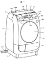
図1は本発明の一実施例の形態例に係るドラム式洗濯乾燥機の外観図である。図2は内部の構造を示すために筐体の一部を切断して示した斜視図、図3は内部の構造を示すために背面カバーを取り外した背面図、図4は内部の構造を示す側面図、図5は内部の構造を示すために筐体の一部を切断して示した平面図である。 FIG. 1 is an external view of a drum type washing / drying machine according to an embodiment of the present invention. FIG. 2 is a perspective view showing a part of the casing cut off to show the internal structure, FIG. 3 is a rear view with the back cover removed to show the internal structure, and FIG. 4 shows the internal structure. FIG. 5 is a side view, and FIG. 5 is a plan view showing a part of the housing cut away to show the internal structure.
1は、外郭を構成する筐体である。筐体1は、ベース1hの上に取り付けられており、左右の側板1a,1b,前面カバー1c,背面カバー1d,上面カバー1e,下部前面カバー1fで構成されている。左右の側板1a,1bは、コの字型の上補強材(図示せず)、前補強材(図示せず)、後補強材(図示せず)で結合されており、ベース1を含めて箱状の筐体1を形成し、筐体として十分な強度を有している。
9は、前面カバー1cの略中央に設けた衣類を出し入れするための投入口を塞ぐドアで、前補強材に設けたヒンジで開閉可能に支持されている。ドア開放ボタン9dを押すことでロック機構(図示せず)が外れてドアが開き、ドアを前面カバー1cに押し付けることでロックされて閉じる。前補強材は、後述する外槽の開口部と同心に、衣類を出し入れするための円形の開口部を有している。
9 is a door which closes the insertion port for putting in and taking out the clothes provided in the approximate center of the
6は、筐体1の上部中央に設けた操作パネルで、電源スイッチ39,操作スイッチ12,13,表示器14を備える。操作パネル6は、筐体1下部に設けた制御装置38に電気的に接続している。
3は、回転可能に支持された円筒状の洗濯兼脱水槽(回転ドラム)であり、その外周壁および底壁に通水および通風のための多数の貫通孔を有し、前側端面に衣類を出し入れするための開口部3aを設けてある。開口部3aの外側には洗濯兼脱水槽3と一体の流体バランサー3cを備えている。外周壁の内側には軸方向に延びるリフター3bが複数個設けてあり、洗濯,乾燥時に洗濯兼脱水槽3を回転すると、衣類はリフター3bと遠心力で外周壁に沿って持ち上がり、重力で落下するように動きを繰り返す。洗濯兼脱水槽3の回転中心軸は、水平または開口部3a側が高くなるように傾斜している。
3 is a cylindrical washing and dewatering tub (rotary drum) supported rotatably, having a large number of through holes for water flow and ventilation on its outer peripheral wall and bottom wall, and clothing on the front end face An
2は、円筒状の外槽であり、洗濯兼脱水槽3を同軸上に内包し、前面は開口し、後側端面の外側中央にモータ4を取り付ける。モータ4の回転軸は、外槽2を貫通し、洗濯兼脱水槽3と結合している。前面の開口部には外槽カバー2dを設け、外槽内への貯水を可能としている。外槽カバー2dの前側中央には、衣類を出し入れするための開口部2cを有している。本開口部2cと前補強材37に設けた開口部は、ゴム製のベローズ10で接続しており、ドア9を閉じることで外槽2を水封する。
外槽2の内側鉛直方向下側には回転中心軸方向に長い凹状の排水溝45が外槽2底面最下部に排水口2bを有して設けられ、排水ホース26が接続している。排水ホース26の途中には排水弁(図示せず)が設けてあり、排水弁を閉じて給水することで外槽2に水を溜め、排水弁を開いて外槽2内の水を機外へ排出する。
A
外槽2は、下側をベース1hに固定されたサスペンション5(コイルばねとダンパで構成)で防振支持されている。また、外槽2の上側は上部補強部材に取り付けた補助ばね(図示せず)で支持されており、外槽2の前後方向へ倒れを防ぐ。
The
19は、筐体1内の上部左側に設けた洗剤容器で、前部開口から引き出し式の洗剤トレイ7を装着する。洗剤類を入れる場合は、洗剤トレイ7を図1の二点鎖線で示すように引き出す。洗剤容器19は、筐体1の上補強材に固定されている。
洗剤容器19の後ろ側には、給水電磁弁16や風呂水給水ポンプ17,水位センサ(図示せず)など給水に関連する部品を設けてある。上面カバー1eには、水道栓からの給水ホース接続口16a,風呂の残り湯の吸水ホース接続口17aが設けてある。洗剤容器19は、外槽2に接続されており、給水電磁弁16を開く、あるいは風呂水給水ポンプ17を運転することで、外槽2に洗濯水を供給する。
On the rear side of the
29は筐体1の背面内側に縦方向に設置した乾燥ダクトで、ダクト下部は外槽2の背面下方に設けた吸気口2aにゴム製の蛇腹管B29aで接続される。乾燥ダクト29内には、水冷除湿機構(図示せず)を内蔵しており、給水電磁弁16から水冷除湿機構へ冷却水を供給する。冷却水は乾燥ダクト29の壁面を伝わって流下し吸気口2aから外槽2に入り排水口2bから排出される。
乾燥ダクト29の上部は、筐体1内の上部右側に前後方向に設置したフィルタダクト27に接続している。フィルタダクト27の前面には開口部を有しており、この開口部に引き出し式の乾燥フィルタ8を挿入してある。乾燥ダクト29からフィルタダクト27へ入った空気は、乾燥フィルタ8のメッシュフィルタ8aに流入し糸くずが除去される。乾燥フィルタ8の掃除は、乾燥フィルタ8を引き出してメッシュ式のフィルタ8aを取り出して行う。また、フィルタダクト27の乾燥フィルタ8挿入部の下面には開口部が設けてあり、この開口部は吸気ダクト33が接続しており、吸気ダクト33の他端は送風ユニット28の吸気口と接続している。
The upper part of the drying
送風ユニット28は、駆動用のモータ28a,ファン羽根車(図示せず),ファンケース28bで構成されている。ファンケース28bにはヒータ31が内蔵されており、ファン羽根車から送られる空気を加熱する。送風ユニット28の吐出口は温風ダクト30に接続する。温風ダクト30は、ゴム製の蛇腹管A30a,蛇腹管継ぎ手30bを介して外槽カバー2dに弾性体などからなる緩衝材32eを介して締結された温風吹き出し口32に接続している。本実施例では、送風ユニット28が筐体1内の上部右側に設けてあるので、温風吹き出し口32は外槽カバー2dの右斜め上の位置に設け、温風吹き出し口32までの距離を極力短くするようにしてある。
The
排水口2b,送風ユニット28の吸気口及び吐出口には温度センサ(図示せず)が設けてある。
Temperature sensors (not shown) are provided at the
本発明のドラム式洗濯乾燥機では、大容量化と乾燥時の仕上がり性能向上および省エネ化を目的に、ドラム径の大径化と脱水回転数の高速化、並びに、温風風量の大風量化と風速の高速化が図られている。 In the drum type washing and drying machine of the present invention, for the purpose of increasing the capacity, improving the finishing performance during drying, and saving energy, the drum diameter is increased, the dehydration speed is increased, and the hot air volume is increased. Wind speed has been increased.
高速の風を衣類に直接当て、風の力で衣類に発生するしわを伸ばすことを特徴とする本洗濯機においては、高速の風を発生する送風ユニット28とこの風を直接衣類に当てる温風吹き出し口32が必要となる。温風吹き出し口32の詳細を図6,図7を用いて説明する。図6は温風吹き出し口28設置部の外槽カバー2dの正面図、図7は図6の二点鎖線A−Aで切断して示した温風吹き出し口32の断面図である。
In the present washing machine characterized in that high-speed wind is directly applied to the clothes and wrinkles generated in the clothes are stretched by the force of the wind, the
温風吹き出し口32は、外槽カバー2dの前側から開口部2cに沿って弾性体などからなる緩衝材32eを介して締結してあり、内部に流路32b,32cが形成されている。温風吹き出し口32の入口には蛇腹管継ぎ手30bが取り付けてあり、流路32cの出口にはノズル32dが形成されている。洗濯兼脱水槽3と外槽カバー2dとのすき間に衣類が入り込まないよう、外槽カバー2dの開口部2cの内径と洗濯兼脱水槽3の開口部3aの内径は、ほぼ同一に設定されている。温風吹き出し口32の出口部32aを開口部2cの内周面より内側に飛び出すように形成し、ノズル32dが洗濯兼脱水槽3内に向かって開口するようにすることで、ノズル32dから出た温風は直接洗濯兼脱水槽3内の衣類に当たる。
The
乾燥運転時の風の流れは次のようになる。送風ユニット28を運転し、ヒータ31に通電すると、ノズル32dから洗濯兼脱水槽3内に高速の温風が吹き込み(矢印41)、湿った衣類に当たり、衣類を温め衣類から水分が蒸発する。高温多湿となった空気は、洗濯兼脱水槽3に設けた貫通孔から外槽2に流れ、吸気口2aから乾燥ダクト29に吸い込まれ、乾燥ダクト29を下から上へ流れる(矢印42)。乾燥ダクト29の壁面には、水冷除湿機構からの冷却水が流れ落ちており、高温多湿の空気は冷却水と接触することで冷却除湿され、乾いた低温空気となりフィルタダクト27へ入る(矢印43)。フィルタダクト27に設けたメッシュフィルタ8aを通り糸屑が取り除かれ、吸気ダクト33に入り、送風ユニット28に吸い込まれる(矢印44)。そして、ヒータ31で再度加熱され、洗濯兼脱水槽3内に吹き込むように循環する。この間、洗濯兼脱水槽3を低速で正逆回転させ、衣類をノズル32dの近くまで持ち上げ、高速の温風が衣類に直接当たるようにする。
The flow of wind during the drying operation is as follows. When the
一般に洗濯機における騒音の主要な発音体は外槽2であり、この外槽2への振動伝達の遮断が騒音低減の有効な手段となる。上述のように、送風ユニット28で発生する振動は幸いにも蛇腹管継ぎ手30bを介した接続構成により外槽2への振動伝達は抑制されている。しかし、風の流れは温風吹き出し口32でその方向を変えることになり、その際風が有している脈動圧力により温風吹き出し口32は加振されることになる。
In general, the main sounding body of noise in a washing machine is the
本発明では、温風吹き出し口32は弾性体などからなる緩衝材32eを介して外槽カバー2dに締結する構成とした特徴を有することで、前記風の脈動圧力で温風吹き出し口32に発生した振動を吸収し、外槽カバー2dへの振動伝達を抑制する機能を働かさせている。
In the present invention, the
ところで、大容量化と省エネ化を特徴とする本洗濯機においては、洗濯兼脱水槽3径の大径化と脱水回転数の高速化が図られている。この際、設置性の関係から筐体1の大きさは制限を受ける。したがって、必然的に外槽2径も制限を受けることになり、外槽2内に内包される洗濯兼脱水槽3径の大径化は、外槽2と洗濯兼脱水槽3の隙間の狭小化を伴うこととなる。この結果、洗濯兼脱水槽3の回転に起因した隙間流れの流体力の外槽2への作用が増大することになる。また、上述しているように、本洗濯機では、外槽2の内側鉛直下側に、回転中心軸方向に長い凹状の排水溝45が設けられているため、高速回転時には上記流体力が、前記排水溝45に働くことになる。
By the way, in this washing machine characterized by large capacity and energy saving, the diameter of the washing and
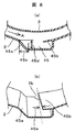
排水溝の詳細を図8(a),図8(b)を用いて説明する。図8(a)は、第2の実施形態の排水溝45における洗濯兼脱水槽3の回転中心軸方向中央部の断面図、図8(b)は斜視図である。図において、洗濯兼脱水槽3の脱水工程時の回転方向は正面から見て反時計回りで(矢印A)方向である。排水溝45は、洗濯兼脱水槽3の回転方向上流側は下流側に向けて傾斜した面で構成され、その傾斜は、幅45cと高さ45dがほぼ等しい程度で、各連結部は滑らかな結合となっている。下流側には、上流側に向けて張り出した庇45bが設けられ、前記庇45b先端はエッジではない丸みを有し、排水口2bを半分程度覆う張り出し長さで洗濯兼脱水槽3の回転中心軸に対し約10度程度のスキュー角45eをもつ特徴を有する構成となっている。前記スキュー角45eは、図とは逆方向であっても、その機能は維持される。
The details of the drainage groove will be described with reference to FIGS. 8 (a) and 8 (b). FIG. 8A is a cross-sectional view of the central portion in the direction of the rotation center axis of the washing and
本発明では、上流側では外槽2と洗濯兼脱水槽3の隙間を無段階に変化させることで急激な圧力変動を抑制し、下流側ではスキュー角45eを設けることで流体力の位相を変化させて作用流体力の分散を図り、流体騒音発生の抑制と作用する流体力を抑制する二つの機能を働かさせている。
In the present invention, the pressure difference is suppressed by changing the gap between the
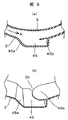
図9(a)は、第3の実施形態の排水溝45における洗濯兼脱水槽3の回転中心軸方向中央部の断面図、図9(b)は斜視図である。図において、洗濯兼脱水槽3の脱水工程時の回転方向は正面から見て反時計回りで(矢印A)方向である。排水溝45は、洗濯兼脱水槽3の回転方向上流側は下流側に向けて傾斜した面で構成され、その傾斜は、幅45cと高さ45dがほぼ等しい程度で、各連結部は滑らかな結合となっている。下流側には、上流側に向けて張り出した庇45bが設けられ、前記庇45b先端はエッジではない丸みを有し、排水口2bを半分程度覆う張り出し長さで洗濯兼脱水槽3の回転中心軸方向長さの中央部が上流側に凸形状の先端付近である特徴を有する構成となっている。
FIG. 9A is a cross-sectional view of the central portion in the rotation center axis direction of the washing and
本発明では、上流側では外槽2と洗濯兼脱水槽3の隙間を無段階に変化させることで急激な圧力変動を抑制し、下流側では中央部凸形状とすることで流体力の位相を変化させて作用流体力の分散を図り、流体騒音発生の抑制と作用する流体力を抑制する二つの機能を働かさせている。
In the present invention, the pressure difference is suppressed by changing the gap between the
図10(a)は、第4の実施形態の排水溝45における洗濯兼脱水槽3の回転中心軸方向中央部の断面図、図10(b)は斜視図である。図において、洗濯兼脱水槽3の脱水工程時の回転方向は正面から見て反時計回りで(矢印A)方向である。排水溝45は、洗濯兼脱水槽3の回転方向上流側は下流側に向けて傾斜した面で構成され、その傾斜は、幅45cと高さ45dがほぼ等しい程度で、各連結部は滑らかな結合となっている。下流側には、上流側に向けて張り出した庇45bが弾性体などからなる緩衝材45f,45g,45hを介して外槽2に突起45iとへこみ45jの嵌合とネジ締結で連結され、前記庇45b先端はエッジではない丸みを有し、排水口2bを半分程度覆う張り出し長さである特徴を有する構成となっている。
FIG. 10A is a cross-sectional view of the central portion in the rotation center axis direction of the washing and
本発明では、上流側では外槽2と洗濯兼脱水槽3の隙間を無段階に変化させることで急激な圧力変動を抑制し、下流側では弾性体などからなる緩衝材を介して外槽2に締結する構成としたことで流体力起因の振動を吸収し、外槽2への振動伝達を抑制する二つの機能を働かさせている。
In the present invention, on the upstream side, the gap between the
以上、本発明の実施例によれば、送風時に発生する流体力に起因し前記温風吹き出し口に発生する振動は、緩衝材により槽カバーへの伝達は抑制され、大きな発音体である外槽の振動が減少し、振動騒音の低減が図られる。また、槽カバーから本体槽への振動伝達も抑制されるので、振動が減少し、振動騒音の低減が図られる。 As described above, according to the embodiment of the present invention, the vibration generated in the hot air outlet due to the fluid force generated at the time of blowing is prevented from being transmitted to the tank cover by the buffer material, and is an outer tank that is a large sounding body. Vibration is reduced, and vibration noise is reduced. In addition, since vibration transmission from the tank cover to the main body tank is also suppressed, vibration is reduced and vibration noise is reduced.
また、脱水運転時の洗濯兼脱水槽回転による排水溝での空気流は、排水溝上流側面の傾斜化及び下流側の庇形状により、乱れが抑制され流体騒音の低減が図られる。また、空気流に起因し前記庇に発生する振動は、緩衝材により槽への伝達は抑制され、大きな発音体である外槽の振動が減少し、振動騒音の低減が図られる。 In addition, the air flow in the drainage groove due to the rotation of the washing / dehydration tank during the dehydration operation is prevented from being disturbed and the fluid noise is reduced by the inclination of the upstream side surface of the drainage groove and the shape of the saddle on the downstream side. Further, the vibration generated in the bag due to the air flow is suppressed from being transmitted to the tank by the buffer material, so that the vibration of the outer tank, which is a large sound generator, is reduced, and the vibration noise is reduced.
これらの結果、送風の高速化と脱水回転数の高速化が達成され、大容量で仕上がり性の良いかつ省エネが達成できるドラム式洗濯乾燥機の提供が可能となる。 As a result, it is possible to provide a drum-type washing / drying machine that achieves a high speed of blowing and a high speed of dewatering rotation, a large capacity, good finish, and energy saving.
1 筐体
2 外槽
2d 外槽カバー
3 洗濯兼脱水槽
4,28a モータ
6 操作パネル
8 乾燥フィルタ
9 ドア
16 給水電磁弁
27 フィルタダクト
28 送風ユニット
28b ファンケース
29 乾燥ダクト
31 ヒータ
32 温風吹き出し口
32d ノズル
33 吸気ダクト
38 制御装置
45 排水溝
DESCRIPTION OF
Claims (7)
衣類を出し入れするための開口部を水封するベローズを有し、乾燥運転中に、前記洗濯兼脱水槽に収容された衣類に直接風を吹きつける手段を設け、該風を吹きつける手段は、送風手段、該送風手段の下流に設けたノズルとで構成し、該ノズルを出口に有する温風吹き出し口の入口には蛇腹管継ぎ手が取り付けられ、前記温風吹き出し口を前記洗濯兼脱水槽の上側に位置する外槽に緩衝材を介して前記ベローズとは別に設置したことを特徴とするドラム式洗濯乾燥機。 A drum-type washing / drying tank comprising a washing / dehydrating tub for storing clothes, an outer tub containing the washing / dehydrating tub, a housing for supporting the outer tub, and a driving means for driving the washing / dehydrating tub In the machine
A bellows that seals the opening for putting in and out the clothes is provided, and during the drying operation, a means for directly blowing air on the clothes accommodated in the washing and dewatering tank is provided, and the means for blowing the wind is: A bellows pipe joint is attached to the inlet of the hot air outlet having the nozzle at the outlet, and the hot air outlet is connected to the washing and dehydrating tank. A drum-type washing and drying machine, wherein the drum is installed separately from the bellows through a cushioning material in an outer tank located on the upper side.
衣類を出し入れするための開口部を水封するベローズを有し、乾燥運転中に、前記洗濯兼脱水槽に収容された衣類に直接風を吹きつける手段を設け、該風を吹きつける手段は、送風手段、該送風手段の下流に設けたノズルとで構成し、該ノズルを出口に有する温風吹き出し口の入口には蛇腹管継ぎ手が取り付けられ、前記温風吹き出し口を前記回転ドラムの上側に位置する外槽に緩衝材を介して前記ベローズとは別に設置したことを特徴とするドラム式洗濯乾燥機。 A circulating water pump unit for circulating washing water, a hot air blowing unit for blowing air, a dehumidifying duct for dehumidification, a water supply / drainage unit for water supply / drainage, and a door for covering the drum opening and process state Washing and detaching with a housing having a display for displaying, a lifter for connecting the center of the bottom to the drive shaft, a fluid balancer on the top and assisting the movement of clothing, and a drain hole for dehydration A water tub, an outer tub that includes the washing / dehydrating tub and is connected to the drain, a blower outlet, and an outlet; an elastic support mechanism that internally supports the outer tub in the housing; In a drum-type washing and drying machine provided with a driving means for driving a water tank, and a control device for controlling driving, water supply / drainage, and ventilation,
A bellows that seals the opening for putting in and out the clothes is provided, and during the drying operation, a means for directly blowing air on the clothes accommodated in the washing and dewatering tank is provided, and the means for blowing the wind is: A bellows pipe joint is attached to the inlet of the hot air outlet having the nozzle at the outlet , and the hot air outlet is located above the rotating drum. A drum-type washing / drying machine, wherein the drum-type washing / drying machine is installed separately from the bellows through a cushioning material in a positioned outer tub.
前記排水溝の一辺である洗濯兼脱水槽回転の上流側を下流側に傾斜させたことを特徴とするドラム式洗濯乾燥機。 A washing / dehydrating tub having a drain hole for dehydration, an outer tub having a drainage groove enclosing the washing / dehydrating tub and connected to a drain outlet, a housing supporting the outer tub, and the washing / dehydrating tub A drum-type washing and drying machine provided with driving means for driving
A drum-type washing / drying machine characterized in that an upstream side of the rotation of the washing and dewatering tank, which is one side of the drainage groove, is inclined to the downstream side.
前記排水溝の一辺である洗濯兼脱水槽回転の上流側を下流側に傾斜させたことを特徴とするドラム式洗濯乾燥機。 A circulating water pump unit for circulating washing water, a hot air blowing unit for blowing air, a dehumidifying duct for dehumidification, a water supply / drainage unit for water supply / drainage, and a door for covering the drum opening and process state Washing and detaching with a housing having a display for displaying, a lifter for connecting the center of the bottom to the drive shaft, a fluid balancer on the top and assisting the movement of clothing, and a drain hole for dehydration A water tub, a drainage groove containing the washing / dehydrating tub and connected to the drainage port, an outer tub having an air blowing outlet and a discharge port, an elastic support mechanism for internally supporting the outer tub in the housing, and the washing / demounting In a drum-type washing and drying machine provided with a driving means for driving a water tank, and a control device for controlling driving and water supply / drainage and blowing,
A drum-type washing / drying machine characterized in that an upstream side of the rotation of the washing and dewatering tank, which is one side of the drainage groove, is inclined to the downstream side.
前記排水溝の一辺である洗濯兼脱水槽回転の下流側に、上流側に向けて洗濯兼脱水槽回転中心軸に対しスキュー角を有する庇を設けたことを特徴とするドラム式洗濯乾燥機。 A circulating water pump unit for circulating washing water, a hot air blowing unit for blowing air, a dehumidifying duct for dehumidification, a water supply / drainage unit for water supply / drainage, and a door for covering the drum opening and process state Washing and detaching with a housing having a display for displaying, a lifter for connecting the center of the bottom to the drive shaft, a fluid balancer on the top and assisting the movement of clothing, and a drain hole for dehydration A water tub, a drainage groove containing the washing / dehydrating tub and connected to the drainage port, an outer tub having an air blowing outlet and a discharge port, an elastic support mechanism for internally supporting the outer tub in the housing, and the washing / demounting In a drum-type washing and drying machine provided with a driving means for driving a water tank, and a control device for controlling driving and water supply / drainage and blowing,
A drum type laundry dryer having a skew angle with respect to the central axis of rotation of the washing and dewatering tub on the downstream side of the rotation of the washing and dewatering tub that is one side of the drainage groove.
前記排水溝の一辺である洗濯兼脱水槽回転の下流側に、上流側に向けて洗濯兼脱水槽回転中心軸に対し先端中央部が凸形状の庇を設けたことを特徴とするドラム式洗濯乾燥機。 A circulating water pump unit for circulating washing water, a hot air blowing unit for blowing air, a dehumidifying duct for dehumidification, a water supply / drainage unit for water supply / drainage, and a door for covering the drum opening and process state Washing and detaching with a housing having a display for displaying, a lifter for connecting the center of the bottom to the drive shaft, a fluid balancer on the top and assisting the movement of clothing, and a drain hole for dehydration A water tub, a drainage groove containing the washing / dehydrating tub and connected to the drainage port, an outer tub having an air blowing outlet and a discharge port, an elastic support mechanism for internally supporting the outer tub in the housing, and the washing / demounting In a drum-type washing and drying machine provided with a driving means for driving a water tank, and a control device for controlling driving and water supply / drainage and blowing,
Drum-type washing characterized in that, on the downstream side of the washing and dewatering tub rotation, which is one side of the drainage groove, a ridge having a convex central portion with respect to the rotation center axis of the washing and dewatering tub is provided upstream. Dryer.
前記排水溝の一辺である洗濯兼脱水槽回転の下流側に、上流側に向けた庇を緩衝材を介して設けたことを特徴とするドラム式洗濯乾燥機。 A circulating water pump unit for circulating washing water, a hot air blowing unit for blowing air, a dehumidifying duct for dehumidification, a water supply / drainage unit for water supply / drainage, and a door for covering the drum opening and process state Washing and detaching with a housing having a display for displaying, a lifter for connecting the center of the bottom to the drive shaft, a fluid balancer on the top and assisting the movement of clothing, and a drain hole for dehydration A water tub, a drainage groove containing the washing / dehydrating tub and connected to the drainage port, an outer tub having an air blowing outlet and a discharge port, an elastic support mechanism for internally supporting the outer tub in the housing, and the washing / demounting In a drum-type washing and drying machine provided with a driving means for driving a water tank, and a control device for controlling driving and water supply / drainage and blowing,
A drum-type washing and drying machine, wherein a paddle facing upstream is provided on the downstream side of the rotation of the washing and dewatering tank, which is one side of the drainage groove, via a cushioning material.
Priority Applications (1)
| Application Number | Priority Date | Filing Date | Title |
|---|---|---|---|
| JP2008256943A JP5156569B2 (en) | 2008-10-02 | 2008-10-02 | Drum type washer / dryer |
Applications Claiming Priority (1)
| Application Number | Priority Date | Filing Date | Title |
|---|---|---|---|
| JP2008256943A JP5156569B2 (en) | 2008-10-02 | 2008-10-02 | Drum type washer / dryer |
Publications (3)
| Publication Number | Publication Date |
|---|---|
| JP2010082345A JP2010082345A (en) | 2010-04-15 |
| JP2010082345A5 JP2010082345A5 (en) | 2011-05-06 |
| JP5156569B2 true JP5156569B2 (en) | 2013-03-06 |
Family
ID=42246874
Family Applications (1)
| Application Number | Title | Priority Date | Filing Date |
|---|---|---|---|
| JP2008256943A Expired - Fee Related JP5156569B2 (en) | 2008-10-02 | 2008-10-02 | Drum type washer / dryer |
Country Status (1)
| Country | Link |
|---|---|
| JP (1) | JP5156569B2 (en) |
Families Citing this family (4)
| Publication number | Priority date | Publication date | Assignee | Title |
|---|---|---|---|---|
| JP5459171B2 (en) * | 2010-10-19 | 2014-04-02 | パナソニック株式会社 | Drum washing machine |
| JP5478578B2 (en) * | 2011-09-28 | 2014-04-23 | 日立アプライアンス株式会社 | Washing and drying machine |
| JP6111412B2 (en) * | 2013-02-01 | 2017-04-12 | パナソニックIpマネジメント株式会社 | Drum washing machine |
| JP6145700B2 (en) * | 2013-03-25 | 2017-06-14 | パナソニックIpマネジメント株式会社 | Drum washing machine |
Family Cites Families (5)
| Publication number | Priority date | Publication date | Assignee | Title |
|---|---|---|---|---|
| JPH11146999A (en) * | 1997-11-17 | 1999-06-02 | Hitachi Ltd | Drum type washing and drying machine |
| JP3530076B2 (en) * | 1999-07-02 | 2004-05-24 | シャープ株式会社 | Drum type washing machine |
| JP2005224351A (en) * | 2004-02-12 | 2005-08-25 | Sharp Corp | Washing and drying machine |
| JP2008110002A (en) * | 2006-10-30 | 2008-05-15 | Hitachi Appliances Inc | Drum type washing-drying machine |
| JP4812595B2 (en) * | 2006-11-08 | 2011-11-09 | 日立アプライアンス株式会社 | Drum type washer / dryer |
-
2008
- 2008-10-02 JP JP2008256943A patent/JP5156569B2/en not_active Expired - Fee Related
Also Published As
| Publication number | Publication date |
|---|---|
| JP2010082345A (en) | 2010-04-15 |
Similar Documents
| Publication | Publication Date | Title |
|---|---|---|
| KR20060089069A (en) | Drum washer having a tub coupled to cabinet and a drying device | |
| JP4836658B2 (en) | Washing and drying machine | |
| JP5325689B2 (en) | Dryer and washing dryer | |
| JP5156569B2 (en) | Drum type washer / dryer | |
| JP5004307B2 (en) | Dryer and washing dryer | |
| JP2005177505A (en) | Washing machine cum drying machine | |
| JP2005198698A (en) | Drum type washing machine | |
| JP6640699B2 (en) | Washing and drying machine | |
| JP2012071069A (en) | Drying machine and washing and drying machine | |
| JP5438648B2 (en) | Drum washing machine | |
| JP5600779B2 (en) | Washing and drying machine | |
| JP2013153839A (en) | Drum-type washing and drying machine | |
| JP2017127338A (en) | Drying machine and washing and drying machine | |
| JP2005095226A (en) | Drum type washing/drying machine | |
| TWI725531B (en) | Laundry dryer | |
| JP2005514130A (en) | Washing machine and dryer with improved drying duct structure | |
| JP5674612B2 (en) | Washing and drying machine | |
| JP4286847B2 (en) | Washing and drying machine | |
| JP2004329778A (en) | Drum type washing machine | |
| JP7054354B2 (en) | Clothes dryer | |
| JP2010075216A (en) | Drying machine and washing and drying machine | |
| JP2013192659A (en) | Drying machine | |
| JP5656797B2 (en) | Drum type washer / dryer | |
| JP6956582B2 (en) | Washing and drying machine | |
| JP7106506B2 (en) | washing machine |
Legal Events
| Date | Code | Title | Description |
|---|---|---|---|
| A521 | Written amendment |
Free format text: JAPANESE INTERMEDIATE CODE: A523 Effective date: 20110223 |
|
| A621 | Written request for application examination |
Free format text: JAPANESE INTERMEDIATE CODE: A621 Effective date: 20110223 |
|
| A521 | Written amendment |
Free format text: JAPANESE INTERMEDIATE CODE: A523 Effective date: 20110223 |
|
| A977 | Report on retrieval |
Free format text: JAPANESE INTERMEDIATE CODE: A971007 Effective date: 20120424 |
|
| A131 | Notification of reasons for refusal |
Free format text: JAPANESE INTERMEDIATE CODE: A131 Effective date: 20120821 |
|
| A521 | Written amendment |
Free format text: JAPANESE INTERMEDIATE CODE: A523 Effective date: 20121022 |
|
| TRDD | Decision of grant or rejection written | ||
| A01 | Written decision to grant a patent or to grant a registration (utility model) |
Free format text: JAPANESE INTERMEDIATE CODE: A01 Effective date: 20121113 |
|
| A61 | First payment of annual fees (during grant procedure) |
Free format text: JAPANESE INTERMEDIATE CODE: A61 Effective date: 20121210 |
|
| FPAY | Renewal fee payment (event date is renewal date of database) |
Free format text: PAYMENT UNTIL: 20151214 Year of fee payment: 3 |
|
| R150 | Certificate of patent or registration of utility model |
Ref document number: 5156569 Country of ref document: JP Free format text: JAPANESE INTERMEDIATE CODE: R150 Free format text: JAPANESE INTERMEDIATE CODE: R150 |
|
| S531 | Written request for registration of change of domicile |
Free format text: JAPANESE INTERMEDIATE CODE: R313531 |
|
| S533 | Written request for registration of change of name |
Free format text: JAPANESE INTERMEDIATE CODE: R313533 |
|
| R350 | Written notification of registration of transfer |
Free format text: JAPANESE INTERMEDIATE CODE: R350 |
|
| LAPS | Cancellation because of no payment of annual fees |