JP5155982B2 - Cleaning device and image forming apparatus having the same - Google Patents
Cleaning device and image forming apparatus having the same Download PDFInfo
- Publication number
- JP5155982B2 JP5155982B2 JP2009247343A JP2009247343A JP5155982B2 JP 5155982 B2 JP5155982 B2 JP 5155982B2 JP 2009247343 A JP2009247343 A JP 2009247343A JP 2009247343 A JP2009247343 A JP 2009247343A JP 5155982 B2 JP5155982 B2 JP 5155982B2
- Authority
- JP
- Japan
- Prior art keywords
- toner
- polishing roller
- roller
- photosensitive drum
- scraper
- Prior art date
- Legal status (The legal status is an assumption and is not a legal conclusion. Google has not performed a legal analysis and makes no representation as to the accuracy of the status listed.)
- Expired - Fee Related
Links
Images


Description
本発明は、感光体表面を研磨する研磨ローラと、これに当接するスクレーパ及び該スクレーパによって前記研磨ローラ表面から掻き取られたトナーを研磨ローラとスクレーパとの当接部に溜めるためのトナー溜め部材を有するクリーニング装置とこれを備えた複写機やプリンタ等の画像形成装置に関するものである。 The present invention relates to a polishing roller for polishing the surface of a photoreceptor, a scraper that contacts the surface, and a toner storage member for storing toner scraped off from the surface of the polishing roller by the scraper at a contact portion between the polishing roller and the scraper. And an image forming apparatus such as a copying machine and a printer having the same.
複写機やプリンタ等の画像形成装置においては、帯電器によって表面が一様に帯電された感光体が光走査装置によって露光走査され、その表面に画像情報に応じた静電潜像が形成される。そして、静電潜像は現像装置によって現像剤であるトナーを用いて現像されてトナー像として顕像化され、このトナー像は、転写装置によって感光体から用紙上に転写された後に定着装置によって加熱及び加圧されて用紙上に定着され、トナー像が定着された用紙が装置外へ排出されることによって一連の画像形成動作が終了する。尚、転写プロセスにおいて用紙上に転写されないで感光体上に残留するトナー(転写残トナー)は、クリーニング装置によって除去されて回収される。 In an image forming apparatus such as a copying machine or a printer, a photosensitive member whose surface is uniformly charged by a charger is exposed and scanned by an optical scanning device, and an electrostatic latent image corresponding to image information is formed on the surface. . The electrostatic latent image is developed by a developing device using toner as a developer to be visualized as a toner image. The toner image is transferred from a photosensitive member to a sheet by a transfer device and then fixed by a fixing device. A series of image forming operations is completed by heating and pressurizing and fixing on the paper, and discharging the paper on which the toner image is fixed to the outside of the apparatus. Incidentally, the toner (transfer residual toner) which is not transferred onto the sheet in the transfer process but remains on the photosensitive member is removed and collected by the cleaning device.
ところで、a−Si(アモルファスシリコン)感光体を用いた画像形成装置においては、a−SiはOPC(有機感光体)に比べて非常に硬いために削れにくく、a−Si感光体の長寿命化が図られる反面、感光体表面に付着した放電生成物等の汚染物質を除去することが困難になる。 By the way, in an image forming apparatus using an a-Si (amorphous silicon) photoconductor, a-Si is very hard compared to OPC (organic photoconductor) and is therefore difficult to be scraped, and the life of the a-Si photoconductor is extended. However, it is difficult to remove contaminants such as discharge products adhering to the surface of the photoreceptor.
そこで、トナーに酸化チタン等の外添剤を添加し、トナーが付着した弾性を有する研磨ローラを感光体に当接させつつ回転させることによって感光体表面を研磨し、感光体表面に付着した放電生成物等の汚染物質を削り取ることによって感光体表面を清浄化し、汚染物質の吸湿による画像流れ等の発生を防ぐようにしている。 Therefore, an external additive such as titanium oxide is added to the toner, and the surface of the photosensitive member is polished by rotating an elastic polishing roller having the toner attached thereto while being in contact with the photosensitive member. The surface of the photoreceptor is cleaned by scraping off contaminants such as products to prevent the occurrence of image flow and the like due to moisture absorption of the contaminants.
ところが、研磨ローラにトナーが付着し過ぎた場合には、搬送される中間転写ベルトや用紙上にトナーが落下して画像不良が発生したり、クリーニング装置内にトナー詰まりが発生する可能性がある。 However, if the toner adheres too much to the polishing roller, the toner may fall on the intermediate transfer belt or the paper to be transported and an image defect may occur, or toner clogging may occur in the cleaning device. .
そこで、特許文献1には、研磨ローラ表面にスクレーパをカウンタ方向に圧接して研磨ローラ上のトナー量を規制し、回収部へのトナーの搬送をスムーズに行うようにした構成が提案されている。 Therefore, Patent Document 1 proposes a configuration in which a scraper is pressed against the surface of the polishing roller in the counter direction to regulate the amount of toner on the polishing roller, so that the toner is smoothly conveyed to the collection unit. .
しかしながら、幅方向に偏ったパターンの印字動作を続けた場合には、印字されない領域では研磨剤を含んだトナーを研磨ローラ上に十分保持させることができず、a−Si感光体表面に付着した放電生成物の研磨による除去作用が低下し、感光体の表面摩擦係数が増加する。そして、感光体の表面摩擦係数が増加すると、転写不良や感光体の駆動トルクの上昇、高湿環境下での画像流れ等の問題が発生する。 However, when the printing operation of the pattern biased in the width direction is continued, the toner containing the abrasive cannot be sufficiently held on the polishing roller in the non-printed area, and adheres to the surface of the a-Si photosensitive member. The action of removing the discharge product by polishing decreases, and the surface friction coefficient of the photoreceptor increases. When the surface friction coefficient of the photoconductor increases, problems such as transfer failure, an increase in drive torque of the photoconductor, and image flow in a high humidity environment occur.
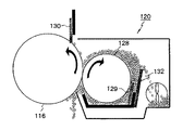
そこで、図7に示すクリーニング装置120のように、フィルム状の薄いトナー溜め部材132をスクレーパ129の近くに設け、スクレーパ129によって研磨ローラ128の表面から掻き取られたトナーをトナー溜め部材132によって研磨ローラ128とスクレーパ129との当接部(以下、「滞留部」と称する)に溜めるようにする構成が提案される。このような構成によれば、研磨剤を含んだ適量のトナーが研磨ローラ128の非画像領域を含む全域に亘って略均一に供給され、研磨ローラ128による感光ドラム116表面の研磨作用が高められて感光ドラム116表面に付着した放電生成物等の汚染物質が確実に除去されて感光ドラム116表面が清浄化される。このため、転写不良や高湿環境下での画像流れ、感光ドラム116の表面摩擦の増加による駆動トルク上昇やクリーニングブレード130の捲れ等の問題が解消される。
Therefore, as in the
又、クリーニングブレード130においては、トナーに含まれる外添剤が該クリーニングブレード130と感光ドラム116との間を僅かに擦り抜けることによって潤滑剤の役目を果たすが、トナー溜め部材132によって溜められたトナーが研磨ローラ128の全域に亘って均一に供給されるため、感光ドラム116表面の摩擦係数が全域に亘って低く抑えられ、この感光ドラム116表面に当接するクリーニングブレード130の捲れが防がれる。
In the
ところが、図7に示すようにトナー溜め部材132を設ける構成を採用すると、トナー溜め部材132によって研磨ローラ128との間の滞留部にトナーが図8に示すようにトナー溜め部材132の高さ以上に溜った場合には、その溜ったトナーが押圧され、その一部が図示のようにスクレーパ129と研磨ローラ128との間を擦り抜ける現象が発生する。このような現象が発生すると、擦り抜けたトナーによって研磨ローラ128上のトナー層厚が厚くなり、これが原因で感光ドラム116の研磨ムラが発生したり、擦り抜けたトナー同士或いはスクレーパ129等との摺擦によってトナーの帯電量が増加することによる微小黒点が発生したり、不図示の中間転写ベルトや用紙上へのトナーの落下による画像不良等の発生が引き起こされる。
However, when the configuration in which the
本発明は上記問題に鑑みてなされたもので、その目的とする処は、トナー溜め部材によって溜められたトナーのスクレーパと研磨ローラの間からの擦り抜けを防ぎ、研磨ローラ上のトナー層厚を適正に保つことによって感光体の研磨ムラや画像不良の発生を防ぐことができるクリーニング装置とこれを備えた画像形成装置を提供することにある。 The present invention has been made in view of the above problems, and the object of the present invention is to prevent the toner accumulated by the toner reservoir member from passing through between the scraper and the polishing roller, and to increase the toner layer thickness on the polishing roller. An object of the present invention is to provide a cleaning device and an image forming apparatus provided with the same that can prevent the occurrence of uneven polishing of the photosensitive member and the occurrence of image defects by keeping them appropriately.
上記目的を達成するため、請求項1記載の発明は、感光体に当接しつつ回転して感光体表面を研磨する研磨ローラと、該研磨ローラに当接して研磨ローラ表面からトナーを掻き取るスクレーパと、該スクレーパによって前記研磨ローラ表面から掻き取られたトナーを研磨ローラとスクレーパとの当接部に溜めるためのトナー溜め部材を備えたクリーニング装置において、前記トナー溜め部材と前記スクレーパとの間に溜められたトナーを崩すトナー崩し部材を設けたことを特徴とする。 In order to achieve the above object, a first aspect of the present invention is a polishing roller that rotates while abutting on a photoconductor to polish the surface of the photoconductor, and a scraper that contacts the polishing roller and scrapes toner from the surface of the polishing roller. And a cleaning device comprising a toner reservoir member for collecting toner scraped off from the surface of the polishing roller by the scraper at a contact portion between the polishing roller and the scraper, between the toner reservoir member and the scraper. A toner breaker member for breaking the accumulated toner is provided.
請求項2記載の発明は、請求項1記載の発明において、前記トナー崩し部材を弾性部材で構成するとともに、その一部を前記トナー溜め部材に当て、該トナー崩し部材を弾性変形させて前記トナー溜め部材を揺動させるようにしたことを特徴とする。 According to a second aspect of the present invention, in the first aspect of the present invention, the toner breaking member is made of an elastic member, a part of the toner breaking member is applied to the toner reservoir member, and the toner breaking member is elastically deformed to form the toner. The reservoir member is rocked.
請求項3記載の発明は、請求項2記載の発明において、前記研磨ローラによって前記感光体から掻き取られたトナーを回収するトナー回収部材を備え、該トナー回収部材の回転動作によって前記トナー崩し部材を弾性変形させることを特徴とする。 According to a third aspect of the present invention, in the second aspect of the present invention, the toner collecting member for collecting the toner scraped off from the photoconductor by the polishing roller is provided, and the toner breaking member is rotated by the rotation of the toner collecting member. Is elastically deformed.
請求項4記載の発明は、請求項1〜3の何れかに記載の発明において、前記トナー崩し部材を前記トナー溜め部材と一体に構成したことを特徴とする。 According to a fourth aspect of the invention, in the invention according to any one of the first to third aspects, the toner breaking member is formed integrally with the toner reservoir member.
請求項5記載の画像形成装置は、請求項1〜4の何れかに記載のクリーニング装置を備えることを特徴とする。 An image forming apparatus according to a fifth aspect includes the cleaning apparatus according to any one of the first to fourth aspects.
本発明によれば、トナー溜め部材によって研磨ローラとの滞留部に溜められたトナーの山がトナー崩し部材によって崩され、滞留部にトナーがトナー溜め部材の高さ以上に溜ることがない。このため、溜ったトナーが押圧されて一部がスクレーパと研磨ローラとの間を擦り抜ける現象の発生が防がれ、研磨ローラ上のトナー層厚が常に適正に保たれる。この結果、感光体の研磨ムラやクリーニングブレードの捲れ、擦り抜けたトナー同士或いはスクレーパ等との摺擦によってトナーの帯電量が増加することによる微小黒点の発生、中間転写ベルトや用紙上へのトナーの落下による画像不良等の発生が防がれ、良好な画像が安定して得られる。 According to the present invention, the crest of toner accumulated in the staying portion with the polishing roller by the toner reservoir member is collapsed by the toner breaking member, so that the toner does not accumulate more than the height of the toner reservoir member. For this reason, the phenomenon that the accumulated toner is pressed and a part of the toner is rubbed between the scraper and the polishing roller is prevented, and the thickness of the toner layer on the polishing roller is always properly maintained. As a result, uneven polishing of the photosensitive member, wobbling of the cleaning blade, generation of minute black spots due to increase in the charge amount of the toner due to rubbing between the scraped toner or scrapers, toner on the intermediate transfer belt or paper Occurrence of an image defect or the like due to the falling of the image is prevented, and a good image can be stably obtained.
以下に本発明の実施の形態を添付図面に基づいて説明する。 Embodiments of the present invention will be described below with reference to the accompanying drawings.
[画像形成装置]
図1は本発明に係る画像形成装置の一形態としてのレーザープリンタの側断面図であり、図示のレーザープリンタ1においては、矩形ボックス状のプリンタ本体(筐体)2の上面の中央部に、傾斜した凹状の排紙トレイ3が設けられている。そして、プリンタ本体2の前面(図1の左側が前方)上部には開閉可能な手差しトレイ4が設けられおり、この手差しトレイ4とその奥のプリンタ本体2内に回転可能に設けられた手差し用の給紙ローラ5は手差し給紙部6を構成している。
[Image forming apparatus]
FIG. 1 is a side sectional view of a laser printer as an embodiment of an image forming apparatus according to the present invention. In the illustrated laser printer 1, a rectangular box-shaped printer body (housing) 2 has a central portion on the upper surface thereof. An inclined concave paper discharge tray 3 is provided. An openable and closable manual feed tray 4 is provided at the upper part of the front surface of the printer main body 2 (the left side in FIG. 1 is the front). The
而して、レーザープリンタ1は、プリンタ本体2内に設けられた搬送路Lに沿って記録材である用紙Pを搬送しながら、不図示の端末等から送信される画像データに基づいて用紙Pに画像を形成するものであって、前記搬送路Lは、側面視略L字状を成して前記排紙トレイ3へと延びている。
Thus, the laser printer 1 transfers the paper P based on image data transmitted from a terminal (not shown) while transporting the paper P as a recording material along the transport path L provided in the
又、レーザープリンタ1は、プリンタ本体2の下部に設けられたカセット給紙部7と、該カセット給紙部7上方のプリンタ本体2内の略中央部に設けられた画像形成部8と、該画像形成部8の後方に配された定着装置9と、該定着装置9上方のプリンタ本体2の上面に設けられた凹状の排紙部10を備えている。
The laser printer 1 includes a cassette
上記カセット給紙部7は、上面が開放された矩形トレイ状の給紙カセット11内に複数枚の用紙Pを積層収容するとともに、給紙カセット11内の用紙Pを1枚ずつ取り出すピックローラ12と、取り出された用紙Pを1枚ずつ分離して搬送路Lへと送り出すフィードローラ13とリタードローラ14を備えており、搬送路Lには、送り出された用紙Pを一時待機させた後に所定のタイミングで画像形成部8へと供給するレジストローラ対15が設けられている。
The cassette
前記画像形成部8は、手差し給紙部6又はカセット給紙部7から1枚ずつ供給された用紙Pに画像データに応じた画像を形成するものであって、プリンタ本体2内の略中央部に回転可能に配された感光体としての感光ドラム16と、その周囲に配置された帯電手段である帯電ローラ17、現像手段である現像装置18、転写手段である転写ローラ19及びクリーニング装置20と、これらの上方に配置されたレーザースキャナユニットト(LSU)21、補給用のトナーを収容したトナーホッパー22等を備えている。
The
又、前記定着装置9は、画像形成部8において用紙Pに転写されたトナー像を当該用紙Pに定着させるためのものであって、互いに圧接されて回転する定着ローラ23と加圧ローラ24を備えている。尚、定着ローラ23にはヒータ等の加熱手段が内蔵されており、加圧ローラ24はバネ等の付勢手段によって定着ローラ23に所定圧で加圧されており、両者間には定着ニップが形成されている。
The fixing
更に、前記排紙部10は、定着装置9においてトナー像が定着された用紙Pをプリンタ本体2外へと排出するためのものであって、搬送路Lの末端に設けられた上下一対の排紙ローラ対25と、前記定着装置9から搬送路Lに沿って搬送される用紙Pを前記搬送ローラ対25へと案内する縦リブ状の複数の搬送ガイドリブ26及びプリンタ本体2外へと排出される用紙Pを積載するための前記排紙トレイ3を備えている。
Further, the
次に、以上の構成を有するレーザープリンタ1の画像形成動作について説明する。 Next, an image forming operation of the laser printer 1 having the above configuration will be described.
例えば、パーソナルコンピュータ(パソコン)等の端末から当該レーザープリンタ1にプリント開始信号が送信されると、画像形成部8においては、感光ドラム16が不図示の駆動手段によって図1の矢印方向(反時計方向)に所定のプロセススピードで回転駆動され、その表面が帯電ローラ17によって所定の電位に一様に帯電される。そして、端末から送信された画像データに基づくレーザー光がレーザースキャナユニット21から出力されて感光ドラム16上に照射されると、該感光ドラム16上には画像データに応じた静電潜像が形成される。そして、この感光ドラム16上に形成された静電潜像は、現像装置18によって現像剤であるトナーを用いて現像されてトナー像として可視像化される。
For example, when a print start signal is transmitted to the laser printer 1 from a terminal such as a personal computer (personal computer), the
ところで、カセット給紙を行う場合、カセット給紙部7の給紙カセット11内に収容された用紙Pは、ピックローラ12によって最上位のものから1枚ずつピックアップされ、フィードローラ13とリタードローラ14によって1枚ずつ分離されてレジストローラ対15へと搬送される。そして、レジストローラ対15においては、用紙Pは、一時待機状態とされた後、感光ドラム16上のトナー像と同期する所定のタイミングで画像形成部8へと供給される。
By the way, when cassette feeding is performed, the paper P stored in the
画像形成部8においては、感光ドラム16と転写ローラ19との間の転写ニップへと供給された用紙Pは、転写ローラ19によって感光ドラム16に押し付けられながら搬送されることによって、その表面(転写面)に感光ドラム16上のトナー像が転写される。そして、トナー像が転写された用紙Pは、定着装置9へと搬送され、この定着装置9において定着ローラ23と加圧ローラ24の定着ニップに挟み込まれて搬送される過程で加熱及び加圧されてトナー像の定着を受ける。尚、用紙Pへのトナー像の転写後に感光ドラム16の表面に残留するトナー(転写残トナー)はクリーニング装置20によって除去され、表面が清掃された感光ドラム16は次の画像形成動作に備えられる。
In the
而して、定着装置9にて表面にトナー像が定着された用紙Pは、搬送路Lを上方へと排紙部10に向かって搬送され、搬送ガイドリブ26に沿って排紙ローラ対25へと導かれ、排紙ローラ対25によって挟み込まれた状態でプリンタ本体2外へと送り出され、プリンタ本体2の上部に設けられた排紙トレイ3上に積載され、一連の画像形成動作が終了する。
Thus, the sheet P having the toner image fixed on the surface thereof by the fixing
尚、ユーザーが手差しで給紙する場合には、手差し給紙部6の手差しトレイ4上に積載された用紙Pが手差し用の給紙ローラ5によってレジストローラ対15へと供給され、以後は前述と同様のプロセスを経て用紙Pに画像が形成され、画像が形成された用紙Pはプリンタ本体2外の排紙トレイ3上に積載される。
When the user manually feeds the paper, the paper P stacked on the manual tray 4 of the manual
[クリーニング装置]
次に、本発明に係る前記クリーニング装置20の実施の形態について説明する。
[Cleaning device]
Next, an embodiment of the
<実施の形態1>
図2は本発明に係るクリーニング装置の側断面図、図3は同クリーニング装置のトナー崩し部材の駆動機構を示す部分斜視図、図4は感光ドラムの摩擦係数の軸方向分布を従来との比較において示す図、図5は感光ドラムの表面層厚の軸方向分布を従来との比較において示す図である。
<Embodiment 1>
2 is a side sectional view of the cleaning device according to the present invention, FIG. 3 is a partial perspective view showing a driving mechanism of a toner breaker member of the cleaning device, and FIG. 4 is a comparison of the axial distribution of the coefficient of friction of the photosensitive drum with the conventional one. FIG. 5 is a diagram showing the axial distribution of the surface layer thickness of the photosensitive drum in comparison with the prior art.
図2に示すクリーニング装置20のハウジング27内には、感光ドラム16に当接しつつ回転して感光ドラム16の表面を研磨する研磨ローラ28と、該研磨ローラ28に当接して研磨ローラ28の表面からトナーを掻き取るスクレーパ29が収納されており、スクレーパ29は研磨ローラ28の回転方向(図2の時計方向)に対してカウンタ方向に当接している。尚、本実施の形態では、感光ドラム16にはa−Si感光体が使用されており、トナーには研磨剤として酸化チタン等の外添剤が添加されている。又、研磨ローラ28はゴム等の弾性体によって構成されており、スクレーパ29としては厚さ0.08〜0.12mm程度のSUS材が使用されている。
In the
又、ハウジング27の感光ドラム16に対向する開口部の上部には、感光ドラム16の表面に当接して該感光ドラム16上に残留する転写残トナーを掻き取るためのクリーニングブレード30が取り付けられている。尚、このクリーニングブレード30は、感光ドラム16の表面の前記研磨ローラ28の当接点よりも下流側(感光ドラム16の回転方向下流側)において感光ドラム16の回転方向に対してカウンタ方向に当接している。
A
ところで、前記スクレーパ29はフレーム31に取り付けられているが、このフレーム31にはフィルム状の薄いトナー溜め部材32が研磨ローラ28から離間した状態で取り付けられている。このトナー溜め部材32は、後述のようにスクレーパ29によって感光ドラム16の表面から掻き取られたトナーを研磨ローラ28とスクレーパ29との当接部(滞留部)に溜めるためのものであって、本実施の形態では厚さ0.1mmのPETフィルムで構成されている。
Incidentally, the
又、図2に示すように、ハウジング27内のトナー溜め部材32の外側には回転可能なトナー回収スクリュー33が収容されており、このトナー回収スクリュー33は、後述のようにトナー溜め部材32によって研磨ローラ28との間の滞留部に溜められてトナー溜め部材32からオーバーフローする不要なトナーを長手方向(図2の紙面垂直方向)に搬送して回収する機能を果たす。
As shown in FIG. 2, a rotatable
ところで、本実施の形態では、トナー溜め部材32によって滞留部に溜められたトナーの山を崩すためのトナー崩し部材34が設けられているが、このトナー崩し部材34は、トナー溜め部材32と一体に構成されている。即ち、本実施の形態では、PETフィルムが逆V字状に折り曲げられ、その折り曲げられた一方の面によってトナー溜め部材32が構成され、他方の面によってトナー崩し部材34が構成されている。そして、図3に示すように、トナー崩し部材34の端部は縦方向の複数の切り込み(スリット)が幅方向に適当な間隔で形成されることによって短冊状に形成されており、この部分はトナー回収スクリュー33の羽根33aに接触している。
By the way, in the present embodiment, the
而して、図1に示すレーザープリンタ1における前記画像形成動作の過程でトナー像が用紙Pに転写された後の感光ドラム16は、トナーが付着した研磨ローラ28によって表面が研磨され、感光ドラム16からは汚染物質と共にトナーが掻き取られて研磨ローラ28に保持される。
Thus, the surface of the
又、研磨ローラ28によって研磨された感光ドラム16上に残留するトナーは、クリーニングブレード30によって掻き取られて研磨ローラ28上に落下し、表面がクリーニングされた感光ドラム16は次の画像形成に備えられるが、トナーはクリーニングブレード30と感光ドラム16の間を僅かに擦り抜け、これに含まれる研磨剤が潤滑剤の役目を果たすため、感光ドラム16の摩擦係数の増加が抑えられ、該感光ドラム16の表面を摺擦するクリーニングブレード30の捲れが防がれる。このとき、研磨ローラ28は、これに保持されたトナーをクリーニングブレード30に供給する機能も果たす。
The toner remaining on the
ところで、本実施の形態では、ハウジング27内の研磨ローラ28の近傍にトナー溜め部材32を設けたため、スクレーパ29によって研磨ローラ28の表面から掻き取られたトナーがトナー溜め部材32によって研磨ローラ28とスクレーパ29との当接部に溜められる。このため、研磨剤を含んだ適量のトナーが研磨ローラ28の非画像領域を含む全域に亘って略均一に供給され、研磨ローラ28による感光ドラム16表面の研磨作用が高められて該感光ドラム16表面に付着した放電生成物等の汚染物質が確実に除去されて感光ドラム16表面が清浄化され、転写不良や高湿環境下での画像流れ、感光ドラム16の表面摩擦の増加による駆動トルクの上昇やクリーニングブレード30の捲れ等の問題が解消される。
Incidentally, in the present embodiment, since the
そして、トナー溜め部材32によって研磨ローラ28との間の滞留部に溜められたトナーは、トナー溜め部材32からオーバーフローして落下し、この落下したトナーは回転するトナー回収スクリュー33によって長手方向(図2の紙面垂直方向)に搬送されて回収されるが、トナー回収スクリュー33が回転すると、該トナー回収スクリュー33の羽根33aに接触するトナー崩し部材34の短冊状の端部が羽根33aによって交互に揺動して振動するため、その振動によってトナー溜め部材32が弾性変形して図2の矢印方向に揺動する。このため、トナー溜め部材32によって研磨ローラ28との滞留部に溜められたトナーの山がトナー溜め部材32の揺動によって崩され、滞留部にトナーがトナー溜め部材32の高さ以上に溜ることがない。
Then, the toner accumulated in the staying portion between the polishing
上述のように、滞留部にトナーがトナー溜め部材32の高さ以上に溜ることがないため、滞留部に溜まったトナーが自重によって押圧されることがなく、その一部がスクレーパ29と研磨ローラ28との間を擦り抜ける現象の発生が防がれ、研磨ローラ28上のトナー層厚が常に適正に保たれる。この結果、感光ドラム16の研磨ムラやクリーニングブレード30の捲れ、擦り抜けたトナー同士或いはスクレーパ29等との摺擦によってトナーの帯電量が増加することによる微小黒点の発生、用紙上へのトナーの落下による画像不良等の発生が防がれ、良好な画像が安定して得られる。
As described above, since the toner does not accumulate in the staying portion more than the height of the
ここで、本発明の実施例について説明する。 Here, examples of the present invention will be described.
本実施例では以下の条件でトナー溜まりと黒点の有無を観察するとともに、感光ドラムの摩擦係数と表面層厚の軸方向分布を測定した。 In this example, the presence or absence of toner pools and black spots was observed under the following conditions, and the axial distribution of the coefficient of friction and surface layer thickness of the photosensitive drum was measured.
・実験機:京セラミタ社製FS−4000DN(A4モノクロ)改造機
・環境:温度32℃/相対湿度80%
・システム構成:
感光ドラム:直径φ30mm、周速180mm/s
研磨ローラ:直径φ14mm、材質EPDM製スポンジ、厚さ2mm
スクレーパ:材質SUS、厚さ8μm、食い込み量0.2mm
トナー溜め部材:材質PETフィルム、厚さ100μm、スクレーパ間距離2mm
・実験条件:印字率6%の原稿を10,000枚印字した後に以下の4項目を観測又は測定する。
・ Experimental machine: FS-4000DN (A4 monochrome) modified machine manufactured by Kyocera Mita ・ Environment:
·System configuration:
Photosensitive drum: Diameter φ30mm, peripheral speed 180mm / s
Polishing roller: Diameter φ14mm, material EPDM sponge, thickness 2mm
Scraper: material SUS, thickness 8μm, bite depth 0.2mm
Toner reservoir member: Material PET film, thickness 100 μm,
Experimental conditions: The following four items are observed or measured after 10,000 originals with a printing rate of 6% are printed.
1)トナー溜め部材高さからの高低(目視)
2)黒点の有無(白紙印刷で目視)
3)感光ドラムの表面摩擦係数の軸方向分布(測定)
4)感光ドラムの表面膜厚の軸方向分布(測定)
・実験結果:表1及び図4及び図5に示す。
1) Height from toner reservoir member height (visually)
2) Presence / absence of black spots (viewed with white paper)
3) Axial distribution of surface friction coefficient of photosensitive drum (measurement)
4) Axial distribution (measurement) of surface film thickness of photosensitive drum
Experimental results: shown in Table 1 and FIGS.
トナー崩し部材を設けた場合と設けない場合について、トナー溜まりのトナー溜め部材高さに対する高低と黒点の有無を観察した結果を表1に示すが、トナー崩し部材を設けない場合はトナー溜まりと黒点が観察されたが、トナー崩し部材を設けるとトナー溜まりも黒点も観察されなかった。 Table 1 shows the results of observing the height of the toner reservoir relative to the height of the toner reservoir member and the presence or absence of black spots in the case where the toner breaker member is not provided. Table 1 shows the toner reservoir and black spots when no toner breaker member is provided. However, when the toner breaking member was provided, neither toner reservoir nor black spots were observed.

又、図5にトナー崩し部材を設けた場合と設けない場合の感光ドラム表面の層厚の軸方向分布を示すが、トナー崩し部材を設けない場合には折れ線B’に示すように層厚の絶対値が小さく、軸方向に大きくばらつくが、トナー崩し部材を設けた場合には、折れ線Aに示すように層厚の絶対値が大きく、軸方向のばらつきも小さく抑えられることが分かる。つまり、トナー崩し部材を設けることによって、感光ドラムが軸方向に均一に研磨されるとともに、その研磨量が小さく抑えられて感光ドラムの耐久性が高められる。 FIG. 5 shows the axial distribution of the layer thickness on the surface of the photosensitive drum with and without the toner breaker member. When the toner breaker member is not provided, the layer thickness as shown by the broken line B ′ is shown. Although the absolute value is small and varies greatly in the axial direction, it can be seen that when the toner breaking member is provided, the absolute value of the layer thickness is large as shown by the broken line A, and the variation in the axial direction is also suppressed. In other words, by providing the toner breaking member, the photosensitive drum is uniformly polished in the axial direction, and the polishing amount is suppressed to be small, and the durability of the photosensitive drum is improved.
<実施の形態2>
次に、本発明の実施の形態2を図6に基づいて説明する。
<
Next, a second embodiment of the present invention will be described with reference to FIG.
図6は本発明の実施の形態2に係るクリーニング装置の側断面図であり、本図においては図2に図示したものと同一要素には同一符号を付しており、以下、それらについての再度の説明は省略する。 FIG. 6 is a side sectional view of the cleaning device according to the second embodiment of the present invention. In FIG. 6, the same elements as those shown in FIG. 2 are denoted by the same reference numerals. Description of is omitted.
本実施の形態においては、トナー回収スクリュー33の軸方向(図6の紙面垂直方向)両端に扇形を成す枠状のトナー崩し部材35(図6には一方のみ図示)が配置されている。各トナー崩し部材35は、弾性部材で構成され、その一方の辺がハウジング27の内面に固定され、他方の辺はトナー回収スクリュー33の羽根33aに接触している。又、各トナー崩し部材35の円弧状の外周部は、その一部がトナー溜め部材32の上端部の長手方向(図6の紙面垂直方向)両端に当接している。
In the present embodiment, a fan-shaped frame-shaped toner breaker member 35 (only one of which is shown in FIG. 6) is disposed at both ends of the
而して、本実施の形態においては、トナー回収スクリュー33が回転すると、該トナー回収スクリュー33の羽根33aに接触するトナー崩し部材35が羽根33aによって交互に揺動して振動するため、その振動がトナー溜め部材32に伝播し、該トナー溜め部材32が弾性変形して図6の矢印方向に揺動する。このため、トナー溜め部材32によって研磨ローラ28との滞留部に溜められたトナーの山がトナー溜め部材35の揺動によって崩され、滞留部にトナーがトナー溜め部材32の高さ以上に溜ることがない。この結果、前記実施の形態1と同様に、トナーの一部がスクレーパ29と研磨ローラ28との間を擦り抜ける現象の発生が防がれ、研磨ローラ28上のトナー層厚が常に適正に保たれ、感光ドラム16の研磨ムラやクリーニングブレード30の捲れ、擦り抜けたトナー同士或いはスクレーパ29等との摺擦によってトナーの帯電量が増加することによる微小黒点の発生、用紙上へのトナーの落下による画像不良等の発生が防がれ、良好な画像が安定して得られる。
Thus, in this embodiment, when the
尚、以上は本発明をレーザープリンタとこれに備えられたクリーニング装置に対して適用した形態について説明したが、本発明は、複写機やファクシミリ装置、複合機等を含む他の任意の画像形成装置及びこれに備えられたクリーニング装置に対しても同様に適用可能であることは勿論である。 Although the present invention has been described with respect to an embodiment in which the present invention is applied to a laser printer and a cleaning device provided in the laser printer, the present invention is not limited to any other image forming apparatus including a copying machine, a facsimile machine, and a multifunction machine. Of course, the present invention can be similarly applied to a cleaning device provided in the same.
1 レーザープリンタ(画像形成装置)
2 プリンタ本体
3 排紙トレイ
4 手差しトレイ
5 給紙ローラ
6 手差し給紙部
7 カセット給紙部
8 画像形成部
9 定着装置
10 排紙部
11 給紙カセット
12 ピックローラ
13 フィードローラ
14 リタードローラ
15 レジストローラ対
16 感光ドラム(感光体)
17 帯電ローラ
18 現像装置
19 転写ローラ
20 クリーニング装置
21 レーザースキャナ(LSU)
22 トナーホッパー
23 定着ローラ
24 加圧ローラ
25 排紙ローラ対
26 搬送ガイドリブ
27 クリーニング装置のハウジング
28 研磨ローラ
29 スクレーパ
30 クリーニングブレード
31 フレーム
32 トナー溜め部材
33 トナー回収スクリュー(トナー回収部材)
33a トナー回収スクリューの羽根
34,35 トナー崩し部材
L 搬送路
P 用紙
1 Laser printer (image forming device)
DESCRIPTION OF
17
DESCRIPTION OF SYMBOLS 22 Toner hopper 23
33a Toner
Claims (5)
前記トナー溜め部材と前記スクレーパとの間に溜められたトナーを崩すトナー崩し部材を設けたことを特徴とするクリーニング装置。 A polishing roller that rotates while being in contact with the photoconductor to polish the surface of the photoconductor, a scraper that contacts the polishing roller and scrapes the toner from the surface of the polishing roller, and a toner scraped off from the surface of the polishing roller by the scraper In a cleaning device provided with a toner reservoir member for collecting the toner at a contact portion between the polishing roller and the scraper,
A cleaning device comprising a toner breaking member for breaking the toner accumulated between the toner reservoir and the scraper.
An image forming apparatus comprising the cleaning device according to claim 1.
Priority Applications (1)
| Application Number | Priority Date | Filing Date | Title |
|---|---|---|---|
| JP2009247343A JP5155982B2 (en) | 2009-10-28 | 2009-10-28 | Cleaning device and image forming apparatus having the same |
Applications Claiming Priority (1)
| Application Number | Priority Date | Filing Date | Title |
|---|---|---|---|
| JP2009247343A JP5155982B2 (en) | 2009-10-28 | 2009-10-28 | Cleaning device and image forming apparatus having the same |
Publications (2)
| Publication Number | Publication Date |
|---|---|
| JP2011095357A JP2011095357A (en) | 2011-05-12 |
| JP5155982B2 true JP5155982B2 (en) | 2013-03-06 |
Family
ID=44112368
Family Applications (1)
| Application Number | Title | Priority Date | Filing Date |
|---|---|---|---|
| JP2009247343A Expired - Fee Related JP5155982B2 (en) | 2009-10-28 | 2009-10-28 | Cleaning device and image forming apparatus having the same |
Country Status (1)
| Country | Link |
|---|---|
| JP (1) | JP5155982B2 (en) |
Families Citing this family (6)
| Publication number | Priority date | Publication date | Assignee | Title |
|---|---|---|---|---|
| EP2587318B1 (en) | 2011-10-27 | 2021-03-17 | Kyocera Document Solutions Inc. | Toner transporting device and image forming apparatus including toner transporting device |
| JP5947764B2 (en) * | 2013-09-10 | 2016-07-06 | 京セラドキュメントソリューションズ株式会社 | Cleaning device, image forming apparatus, and toner breaking member |
| JP6638495B2 (en) * | 2016-03-18 | 2020-01-29 | 株式会社リコー | Cleaning device, process unit and image forming device |
| JP6551308B2 (en) * | 2016-05-31 | 2019-07-31 | 京セラドキュメントソリューションズ株式会社 | Cleaning device and image forming apparatus |
| JP2018180476A (en) * | 2017-04-21 | 2018-11-15 | 京セラドキュメントソリューションズ株式会社 | Cleaning device and image forming apparatus |
| JP2020012872A (en) * | 2018-07-13 | 2020-01-23 | 富士ゼロックス株式会社 | Image forming device |
Family Cites Families (8)
| Publication number | Priority date | Publication date | Assignee | Title |
|---|---|---|---|---|
| JPH034287A (en) * | 1989-05-31 | 1991-01-10 | Toshiba Corp | Cleaning device |
| JP2935737B2 (en) * | 1990-10-31 | 1999-08-16 | 三田工業株式会社 | Cleaning equipment |
| JP3576341B2 (en) * | 1996-11-25 | 2004-10-13 | キヤノンファインテック株式会社 | Cleaning device for image forming apparatus |
| JP3671753B2 (en) * | 1999-07-30 | 2005-07-13 | セイコーエプソン株式会社 | Image forming apparatus |
| JP2004004778A (en) * | 2002-04-19 | 2004-01-08 | Ricoh Co Ltd | Cleaning device and image forming device |
| JP4084141B2 (en) * | 2002-09-09 | 2008-04-30 | 株式会社リコー | Cleaning device and image forming device |
| JP2009003327A (en) * | 2007-06-25 | 2009-01-08 | Kyocera Mita Corp | Cleaning device and image forming apparatus with the same |
| JP5069081B2 (en) * | 2007-10-25 | 2012-11-07 | 京セラドキュメントソリューションズ株式会社 | Toner cleaning device |
-
2009
- 2009-10-28 JP JP2009247343A patent/JP5155982B2/en not_active Expired - Fee Related
Also Published As
| Publication number | Publication date |
|---|---|
| JP2011095357A (en) | 2011-05-12 |
Similar Documents
| Publication | Publication Date | Title |
|---|---|---|
| US20080095559A1 (en) | Toner conveyer device, process cartridge, and image forming apparatus | |
| JP5155982B2 (en) | Cleaning device and image forming apparatus having the same | |
| JP2010243829A (en) | Image forming apparatus and cleaning capability recovery process control method | |
| JP5238666B2 (en) | Image forming apparatus | |
| JP2009025773A (en) | Cleaning device and image forming apparatus loaded with the same | |
| JP5216751B2 (en) | Image forming apparatus | |
| JP4995454B2 (en) | Developing device and image forming apparatus having the same | |
| JP6283492B2 (en) | Cleaning device and image forming apparatus having the same | |
| JP2011085853A (en) | Image forming apparatus | |
| JP2008102248A (en) | Image forming apparatus | |
| JP5276828B2 (en) | Cleaning device and image forming apparatus | |
| JP2003241597A (en) | Cleaning device for photoreceptor drum of wet type printer | |
| JP5216745B2 (en) | Image forming apparatus | |
| JP2018124405A (en) | Cleaning device and image forming apparatus | |
| JP2011095356A (en) | Cleaning device and image forming apparatus having the same | |
| JP2013148757A (en) | Cleaning device and image forming apparatus equipped with same | |
| JP5266264B2 (en) | Cleaning device and image forming apparatus | |
| JP5634276B2 (en) | Cleaning device and image forming apparatus equipped with the same | |
| JP2013025097A (en) | Cleaning device and image forming apparatus | |
| JP2013142785A (en) | Image forming apparatus and method for cleaning the same | |
| JP5820768B2 (en) | Cleaning device, image carrier unit including the same, and image forming apparatus | |
| JP5448767B2 (en) | Image forming apparatus | |
| JP2009265217A (en) | Image forming device | |
| JP2010128220A (en) | Cleaning device and image forming apparatus | |
| JP5216750B2 (en) | Image forming apparatus |
Legal Events
| Date | Code | Title | Description |
|---|---|---|---|
| A621 | Written request for application examination |
Free format text: JAPANESE INTERMEDIATE CODE: A621 Effective date: 20111121 |
|
| A977 | Report on retrieval |
Free format text: JAPANESE INTERMEDIATE CODE: A971007 Effective date: 20121107 |
|
| TRDD | Decision of grant or rejection written | ||
| A01 | Written decision to grant a patent or to grant a registration (utility model) |
Free format text: JAPANESE INTERMEDIATE CODE: A01 Effective date: 20121114 |
|
| A61 | First payment of annual fees (during grant procedure) |
Free format text: JAPANESE INTERMEDIATE CODE: A61 Effective date: 20121207 |
|
| FPAY | Renewal fee payment (event date is renewal date of database) |
Free format text: PAYMENT UNTIL: 20151214 Year of fee payment: 3 |
|
| R150 | Certificate of patent or registration of utility model |
Ref document number: 5155982 Country of ref document: JP Free format text: JAPANESE INTERMEDIATE CODE: R150 Free format text: JAPANESE INTERMEDIATE CODE: R150 |
|
| LAPS | Cancellation because of no payment of annual fees |