JP5155771B2 - Fluoropolymer-wrapped gasket - Google Patents
Fluoropolymer-wrapped gasket Download PDFInfo
- Publication number
- JP5155771B2 JP5155771B2 JP2008208970A JP2008208970A JP5155771B2 JP 5155771 B2 JP5155771 B2 JP 5155771B2 JP 2008208970 A JP2008208970 A JP 2008208970A JP 2008208970 A JP2008208970 A JP 2008208970A JP 5155771 B2 JP5155771 B2 JP 5155771B2
- Authority
- JP
- Japan
- Prior art keywords
- fluororesin
- annular
- gasket
- fiber
- annular member
- Prior art date
- Legal status (The legal status is an assumption and is not a legal conclusion. Google has not performed a legal analysis and makes no representation as to the accuracy of the status listed.)
- Expired - Lifetime
Links
Images


Landscapes
- Gasket Seals (AREA)
- Sealing Material Composition (AREA)
Description
本発明は、クッション材である中芯体の外周をフッ素樹脂フィルムで被覆したフッ素樹脂包みガスケットに関し、さらに詳しくは、常温での圧壊特性と高温下の気密特性に優れているフッ素樹脂包みガスケットに関する。 The present invention relates to a fluororesin-wrapped gasket in which the outer periphery of a core body, which is a cushion material, is coated with a fluororesin film, and more particularly relates to a fluororesin-wrapped gasket having excellent crush characteristics at room temperature and airtight characteristics at high temperatures. .
耐薬品性に優れたガスケットとしては、従来よりフッ素樹脂単体からなるガスケット、フッ素樹脂包みガスケット等が知られている。
フッ素樹脂単体からなるガスケットは、優れた耐薬品性を有している反面、クリープや応力緩和が大きいため、単体でガスケットとして用いる場合には、フランジに溝部を設け、該溝部内にガスケットを配置し、配管内側へのガスケット端部の膨出を阻止し、またフッ素樹脂単体からなるガスケットには過大な応力負荷を与えないなど応力負荷管理を行うことが必要であり、また、フッ素樹脂単体からなるガスケットは、高温時には応力緩和が著しいなど、使用上の制約が多く、使用上問題がある。
Conventionally known gaskets having excellent chemical resistance include a gasket made of a fluororesin alone, a fluororesin-wrapped gasket, and the like.
A gasket made of a single fluororesin has excellent chemical resistance, but has a large creep and stress relaxation, so when using it alone as a gasket, provide a groove in the flange and place the gasket in the groove. In addition, it is necessary to manage the stress load such as preventing the gasket end from expanding to the inside of the piping, and not applying an excessive stress load to the gasket made of a single fluororesin. There are many restrictions on use, such as significant stress relaxation at high temperatures, and there are problems in use.
一方、フッ素樹脂包みガスケットは、例えば、図8に示すように、ジョイントシート、石綿等の環状中芯体1をクッション材とし、この環状中芯体1の外周を四フッ化エチレン樹脂(PTFE)、四フッ化エチレン−パーフルオロアルコキシエチレン共重合樹脂(PFA)のような耐熱性、耐薬品性に優れた厚さ0.5mm以下のフッ素樹脂フィルム2で被覆した構造となっている。 On the other hand, for example, as shown in FIG. 8, the fluororesin-wrapped gasket uses an annular core 1 such as a joint sheet or asbestos as a cushioning material, and the outer periphery of the annular core 1 is made of tetrafluoroethylene resin (PTFE). The structure is covered with a fluororesin film 2 having a thickness of 0.5 mm or less and excellent in heat resistance and chemical resistance, such as tetrafluoroethylene-perfluoroalkoxyethylene copolymer resin (PFA).
従って、この種のガスケットの多くは配管のフランジ間を密封するガスケットとして従来使われ、特に腐食性の強い薬液流体用、あるいは汚染を嫌う食品産業用または純水用ガスケットとして広く使われていた。 Therefore, many of these types of gaskets have been conventionally used as gaskets for sealing between the flanges of pipes, and have been widely used especially for chemical fluids that are highly corrosive or for food industries that do not like contamination or pure water.
さらに使用目的によっては、図9に示すように、環状中芯体1が複数の環状シート3,4、3を積層して構成されることがある。そしてこの環状ジョイントシート3には、石綿系または非石綿系のジョイントシートが用いられ、環状シート4には、例えば、石綿系または非石綿系のフェルトシートが用いられていた。
Further, depending on the purpose of use, as shown in FIG. 9, the annular core 1 may be configured by laminating a plurality of
このようなフッ素樹脂包みガスケットは、中芯材を、通常、厚さ0.5mm以下のフッ素樹脂外被で被覆してなる構造を有しているため、ガスケットとしての弾性や強度は主として中芯材に依存し、その結果、前記フッ素樹脂単体からなるガスケットに比してクリープや応力緩和が小さくなるので、耐薬品性が求められる用途で多用されている(なお、従来のフッ素樹脂包みガスケットの一般的な使用条件は、最高使用温度が200℃程度であり、最高圧力が20kgf/cm2 程度である。)。 Since such a fluororesin-wrapped gasket has a structure in which a core material is usually covered with a fluororesin jacket having a thickness of 0.5 mm or less, the elasticity and strength as a gasket are mainly the core. As a result, creep and stress relaxation are smaller than those of the above-mentioned gasket made of a single fluororesin, so that it is frequently used in applications where chemical resistance is required. As for general use conditions, the maximum use temperature is about 200 ° C., and the maximum pressure is about 20 kgf / cm 2. )
これに対して、近年では、環境への配慮から、中芯材であるジョイントシートやフェルト材としては、石綿材料に代わり、非石綿材料が用いられるようになってきている。
しかしながら、フッ素樹脂包みガスケットでは、外被となるフッ素樹脂の摩擦係数が小さいため、過剰な荷重が負荷された場合には、中芯材とフッ素樹脂外被との間で滑りが生じ、中芯材であるジョイントシートやフェルト材が圧壊することがあった。
On the other hand, in recent years, in consideration of the environment, non-asbestos materials have been used instead of asbestos materials as joint sheets and felt materials that are core materials.
However, in the fluororesin-wrapped gasket, the friction coefficient of the fluororesin that is the outer sheath is small, so when an excessive load is applied, slippage occurs between the core material and the fluororesin outer sheath. Joint sheets and felt materials, which are materials, sometimes collapsed.
この圧壊現象は、初期締め付けが過剰になった場合に生じ、フッ素樹脂外被の破壊の前に中芯材がクリープ現象を起こし、ガスケット応力が極端に低下してしまうために、ガスケットが本来有しているシール性能を発揮できなくなってしまう現象である。 This crushing phenomenon occurs when the initial tightening is excessive, and the core material undergoes a creep phenomenon before the fluororesin jacket breaks, resulting in an extremely low gasket stress. This is a phenomenon in which the sealing performance cannot be exhibited.
また、このような圧壊現象は、中芯強度の低い非石綿系ガスケットにおいて、特に顕著であった。 Moreover, such a crushing phenomenon was particularly remarkable in a non-asbestos gasket having a low core strength.
本発明は、上記のような従来技術に伴う問題点を解決しようとするものであって、圧壊特性に優れ、かつ、良好なシール特性を有する非石綿系フッ素樹脂包みガスケットを提供することを目的としている。 The present invention is intended to solve the problems associated with the prior art as described above, and an object thereof is to provide a non-asbestos-based fluororesin-wrapped gasket having excellent crushing properties and good sealing properties. It is said.
本発明に係るフッ素樹脂包みガスケットは、フッ素樹脂外被の環状溝内に、単層(1層)または複数の環状部材を積層してなる環状中芯体が嵌入されたフッ素樹脂包みガスケットであって、前記環状中芯体を構成する少なくとも1層の環状部材(a)が、有機繊維、無機繊維、無機粉体およびバインダーを含むことを特徴としている。 The fluororesin-wrapped gasket according to the present invention is a fluororesin-wrapped gasket in which an annular core formed by laminating a single layer (single layer) or a plurality of annular members is inserted in an annular groove of a fluororesin jacket. Thus, at least one layer of the annular member (a) constituting the annular core includes organic fibers, inorganic fibers, inorganic powders, and a binder.
本発明においては、この環状部材(a)が1層または2層以上含まれる場合、該1層、または2層以上の環状部材のうちの2層がそれぞれフッ素樹脂外被と密接していることが好ましい。換言すれば、フッ素樹脂外被と接する環状部材としては、有機繊維、無機繊維、無機粉体およびバインダーを含むものが好ましい。 In the present invention, when the annular member (a) includes one layer or two or more layers, the two layers of the one-layer or two or more layers of the annular member are in close contact with the fluororesin jacket, respectively. Is preferred. In other words, the annular member in contact with the fluororesin jacket preferably includes organic fibers, inorganic fibers, inorganic powder, and a binder.
本発明においては、この環状部材中に含まれる上記無機粉体は、均一分散していてもよく、環状部材のフッ素樹脂外被側表面に偏在していてもよいが、無機粉体が偏在してなる粉体層(粉体の偏在している表面)は、フッ素樹脂外被と密接していることが好ましい。この環状部材(b)が1層のみの場合はその粉体表面が、また複数の(b)が用いられる場合には、2枚の(b)の粉体側表面がそれぞれフッ素樹脂外被と接していることが好ましい。 In the present invention, the inorganic powder contained in the annular member may be uniformly dispersed or may be unevenly distributed on the surface of the annular member on the fluororesin jacket side, but the inorganic powder is unevenly distributed. The powder layer (the surface on which the powder is unevenly distributed) is preferably in close contact with the fluororesin jacket. When the annular member (b) has only one layer, the surface of the powder, and when a plurality of (b) is used, the two powder-side surfaces of (b) are respectively coated with the fluororesin jacket. It is preferable to contact.
本発明においては、前記無機粉体が、硫酸バリウム、タルク、クレー、酸化チタン、酸化アルミニウム、酸化亜鉛、酸化マグネシウム、ケイ酸、二酸化珪素、炭酸カルシウム、炭酸ナトリウム、水酸化カルシウム、炭酸マグネシウムのうちから選択される少なくとも1種の化合物であることが好ましく、さらには硫酸バリウムであることが望ましい。 In the present invention, the inorganic powder is selected from barium sulfate, talc, clay, titanium oxide, aluminum oxide, zinc oxide, magnesium oxide, silicic acid, silicon dioxide, calcium carbonate, sodium carbonate, calcium hydroxide, and magnesium carbonate. It is preferably at least one compound selected from the group consisting of barium sulfate.
本発明に係るフッ素樹脂包みガスケット用の環状部材は、フッ素樹脂外被の環状溝内に嵌入される環状中芯体を構成する1層または複数の層からなる環状部材であって、前記環状中芯体を構成する1層または複数層の環状部材のうち少なくとも1つの環状部材が、有機繊維、無機繊維、無機粉体およびバインダーを含むことを特徴としている。 An annular member for a fluororesin-wrapped gasket according to the present invention is an annular member composed of one or a plurality of layers constituting an annular core body that is fitted into an annular groove of a fluororesin jacket. At least one annular member among the one-layer or plural-layer annular members constituting the core body includes an organic fiber, an inorganic fiber, an inorganic powder, and a binder.
本発明の上記フッ素樹脂包みガスケット用環状中芯体においては、前記無機粉体が、硫酸バリウム、タルク、クレー、酸化チタン、酸化アルミニウム、酸化亜鉛、酸化マグネシウム、ケイ酸、二酸化珪素、炭酸カルシウム、炭酸ナトリウム、水酸化カルシウム、炭酸マグネシウムのうちから選択される少なくとも1種の化合物であることが好ましく、さらには硫酸バリウムであることが望ましい。 In the annular core for a fluororesin-wrapped gasket of the present invention, the inorganic powder comprises barium sulfate, talc, clay, titanium oxide, aluminum oxide, zinc oxide, magnesium oxide, silicic acid, silicon dioxide, calcium carbonate, It is preferably at least one compound selected from sodium carbonate, calcium hydroxide, and magnesium carbonate, and more preferably barium sulfate.
本発明においては、上記無機粉体の平均粒径が1.5μm以下であることが好ましい。本発明に係る上記フッ素樹脂包みガスケットは、常温での圧壊特性と高温下の気密特性に優れている。 In the present invention, the average particle size of the inorganic powder is preferably 1.5 μm or less. The fluororesin-wrapped gasket according to the present invention is excellent in the crushing property at normal temperature and the airtight property at high temperature.
本発明においては、上記環状部材中に上記有機繊維が5〜40重量%、無機繊維が20〜85重量%、無機粉体が10重量%以上、およびバインダーが残部量(但し、各環状部材重量を100重量%とする。)で含まれていることが望ましい。 In the present invention, the organic fiber in the annular member is 5 to 40% by weight, the inorganic fiber is 20 to 85% by weight, the inorganic powder is 10% by weight or more, and the remaining amount of the binder (however, the weight of each annular member) Is 100% by weight).
本発明においては、上記無機繊維の繊維径が20μm以下、繊維長が0.01mm以上であることが好ましい。
本発明に係るフッ素樹脂包みガスケット用中芯材(非石綿系フェルト材)あるいは該中芯材用の環状部材は、常温での圧壊特性と高温下の気密特性に優れている。
In the present invention, the inorganic fiber preferably has a fiber diameter of 20 μm or less and a fiber length of 0.01 mm or more.
The core material (non-asbestos-based felt material) for fluororesin-wrapped gaskets or the annular member for the core material according to the present invention is excellent in crushing characteristics at normal temperature and airtight characteristics at high temperatures.
以下、本発明に係るフッ素樹脂包みガスケットおよび該ガスケット用の中芯材(フェルト)について、図面に示す好ましい実施態様を参照しつつ具体的に説明する。なお、本明細書および添付図面では、同一部材には、同一符号を付している。 Hereinafter, the fluororesin-wrapped gasket and the core material (felt) for the gasket according to the present invention will be specifically described with reference to preferred embodiments shown in the drawings. In addition, in this specification and an accompanying drawing, the same code | symbol is attached | subjected to the same member.
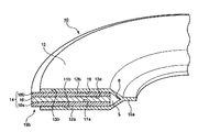
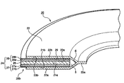
図1は、本発明の一実施態様に係るフッ素樹脂包みガスケットの要部断面を含む部分斜視図である。図2は、本発明の他の実施態様に係るフッ素樹脂包みガスケットの要部断面を含む部分斜視図である。 FIG. 1 is a partial perspective view including a cross section of a main part of a fluororesin-wrapped gasket according to an embodiment of the present invention. FIG. 2 is a partial perspective view including a cross section of a main part of a fluororesin-wrapped gasket according to another embodiment of the present invention.
図1に示す第1のフッ素樹脂包みガスケット10は、環状中芯体14と、この環状中芯体14が装着されるフッ素樹脂外被12とを有している。そしてこのフッ素樹脂外被12の環状溝19内に、複数、特に3層の環状部材18a,16,18bを順次積層してなる上記環状中芯体14が嵌入されている。
A first fluororesin-wrapped
<フッ素樹脂外被>
まずフッ素樹脂外被12は、主としてガスケットの耐薬品性向上に寄与し、変性ポリテトラフルオロエチレン(特公平3−39105号公報参照)、四フッ化エチレン樹脂(PTFE)、四フッ化エチレン-パーフロロアルキルビニルエーテル共重合樹脂(PFA)、四フッ化エチレン-六フッ化プロピレン共重合樹脂(FEP)、四フッ化エチレン-六フッ化プロピレン-パーフロロアルキルビニルエーテル共重合樹脂(EPE)、四フッ化エチレン-エチレン共重合樹脂(ETEE)、フッ化ビニリデン樹脂(PVDF)などのフッ素樹脂で構成されている。
<Fluororesin jacket>
First, the fluororesin jacket 12 mainly contributes to the improvement of chemical resistance of the gasket, and is modified polytetrafluoroethylene (see Japanese Patent Publication No. 3-39105), tetrafluoroethylene resin (PTFE), tetrafluoroethylene-par. Fluoroalkyl vinyl ether copolymer resin (PFA), tetrafluoroethylene-hexafluoropropylene copolymer resin (FEP), tetrafluoroethylene-hexafluoropropylene-perfluoroalkyl vinyl ether copolymer resin (EPE), tetrafluoride It is made of a fluororesin such as ethylene-ethylene copolymer resin (ETEE) or vinylidene fluoride resin (PVDF).
これらのフッ素樹脂は1種または2種以上組み合わせて用いることができる。
<環状部材>
このフッ素樹脂包みガスケット10においては、前記環状中芯体14は、主としてガスケットの弾性や強度向上を受け持ち、上述したように複数の環状シート(環状部材)18a,16,18bを積層して構成されている。この環状中芯体14を構成する環状部材18a,16,18bのうち外被12と密接する環状部材18a,18bは、有機繊維、無機繊維、無機粉体およびバインダーを含んでいる。
These fluororesins can be used alone or in combination of two or more.
<Annular member>
In the fluororesin-wrapped
この環状部材18a,18b中に含まれる無機粉体は、図1に示すように該環状部材中に一様に分散していてもよく、図2に示すように環状部材27,28の外被側表面27b、28bに偏在していてもよい。
The inorganic powder contained in the
特に、含まれる無機粉体が、図1に示すように該環状部材中に一様に分散していていると繊維表面に無機粉体が付着することで有機繊維−有機繊維、有機繊維−無機繊維、無機繊維−無機繊維など繊維の付着力が向上することで、圧壊特性に優れたガスケットが得られるという効果が得られ、また図2に示すように環状部材27,28の外被側表面27b、28bに偏在しているとフッ素樹脂外被と環状部材との付着力が向上し、外被のクリープをおさえてシール特性に優れたガスケットが得られるという効果が得られる。なお、図2において、付番27a、28aは、有機繊維、無機繊維およびバインダーからなるフェルト層を示し、付番27b、28bは、主に無機粉体およびバインダーからなる無機粉体層を示す。
In particular, when the inorganic powder contained is uniformly dispersed in the annular member as shown in FIG. 1, the inorganic powder adheres to the fiber surface, so that organic fiber-organic fiber, organic fiber-inorganic By improving the adhesion of fibers such as fibers and inorganic fibers-inorganic fibers, the effect of obtaining a gasket having excellent crushing characteristics can be obtained, and the outer surface of the
このようなフェルト層27aと無機粉体層27bとが積層されて環状部材27が形成され、フェルト層28aと無機粉体層28bとが積層されて環状部材28が形成されている。
The felt layer 27a and the inorganic powder layer 27b are laminated to form the annular member 27, and the felt layer 28a and the inorganic powder layer 28b are laminated to form the
なお、これら環状部材では、環状部材の外被12側表面11b、13bから環状シート16側に向かって層の厚み方向に連続的に無機粉体含量が低下していてもよい。
In these annular members, the inorganic powder content may continuously decrease in the thickness direction of the layer from the outer member 12
環状シート(環状部材)16は、ゴム板、コルク板、ジョイントシート材から構成され、好ましくはジョイントシート材にて構成されている。ジョイントシート材としては、特に限定されず、例えば、(i)アラミド繊維とゴムからなるもの、(ii)図1の環状部材18a、18b等と同様に、アラミド繊維等の有機繊維と、無機繊維と無機粉体とゴム等のバインダーとからなり、その組成比が前記図1の環状部材18a、18b等とは異なるもの等が挙げられる。この環状シート(環状部材)16には、環状溝奥部5内の気体、液体を外部に排出しうるように、前記環状溝奥部5と外部とを径方向に連通する連通孔などの連通手段が設けられていてもよい。
The annular sheet (annular member) 16 is composed of a rubber plate, a cork plate, and a joint sheet material, and is preferably composed of a joint sheet material. The joint sheet material is not particularly limited. For example, (i) a material made of aramid fiber and rubber, and (ii) an organic fiber such as an aramid fiber and an inorganic fiber, like the
以下、環状部材18a,18bについて詳説する。この環状部材18a,18bには、上記のように有機繊維、無機繊維、無機粉体およびバインダーが含まれている。
Hereinafter, the
有機繊維としては、200℃で100時間の加熱後も初期の50%以上の強度を有している有機繊維(耐熱性有機繊維)が好ましい。このような耐熱性有機繊維としては、例えば、アラミド繊維、カーボン繊維、テフロン繊維等が挙げられ、これらの有機繊維は1種または2種以上組み合わせて用いることができる。これら有機繊維のうちでも、特にフィブリル化可能でありパルプ形状(分岐形状)になる繊維が望ましい。 As the organic fiber, an organic fiber (heat-resistant organic fiber) having an initial strength of 50% or more even after heating at 200 ° C. for 100 hours is preferable. Examples of such heat-resistant organic fibers include aramid fibers, carbon fibers, Teflon fibers, and the like, and these organic fibers can be used alone or in combination of two or more. Among these organic fibers, fibers that can be fibrillated and have a pulp shape (branched shape) are particularly desirable.
無機繊維としては、ガラス繊維、ジルコニア繊維、セラミックス繊維、ロックウールなど従来より公知のものを広く使用可能であり、これらの無機繊維は1種または2種以上組み合わせて用いることができる。 As the inorganic fiber, conventionally known ones such as glass fiber, zirconia fiber, ceramic fiber, rock wool and the like can be widely used, and these inorganic fibers can be used alone or in combination of two or more.
これら無機繊維のうちでも比較的繊維径が小さく(繊維径が20μm以下、好ましくは0.1〜5μm)、しかも繊維長が0.01mm以上、好ましくは0.1〜10mmのものが望ましく、このように繊維径が比較的小さく、繊維長が上記範囲にあるような望ましい無機繊維としては、ロックウールが挙げられる。 Among these inorganic fibers, those having a relatively small fiber diameter (fiber diameter of 20 μm or less, preferably 0.1 to 5 μm) and a fiber length of 0.01 mm or more, preferably 0.1 to 10 mm are desirable. As a desirable inorganic fiber having a relatively small fiber diameter and a fiber length in the above range, rock wool is exemplified.
無機粉体としては、タルク、クレー、酸化チタン、酸化アルミニウム、酸化亜鉛、酸化マグネシウム、ケイ酸、二酸化珪素、炭酸カルシウム、炭酸ナトリウム、水酸化カルシウム、炭酸マグネシウムが挙げられ、これら無機粉体は1種または2種以上組み合わせて用いることができる。これらの無機粉体のうちでは、硫酸バリウムが好ましい。上記無機粉体のうちでも、その平均粒径が通常1.5μm以下、好ましくは0.5μm以下、さらに好ましくは0.2μm以下のものが望ましい。このような粒子径の無機粉体を用いると、無機粉体の表面エネルギーを利用して繊維間の付着性を強め環状部材(フェルト材)強度を向上させることができ、環状部材に適度の柔軟性と緻密性とを付与でき、シール特性と圧壊特性を向上させることが可能となるため好ましい。 Examples of the inorganic powder include talc, clay, titanium oxide, aluminum oxide, zinc oxide, magnesium oxide, silicic acid, silicon dioxide, calcium carbonate, sodium carbonate, calcium hydroxide, and magnesium carbonate. Species or a combination of two or more can be used. Of these inorganic powders, barium sulfate is preferred. Among the inorganic powders, those having an average particle size of usually 1.5 μm or less, preferably 0.5 μm or less, more preferably 0.2 μm or less are desirable. By using inorganic powder having such a particle size, the surface energy of the inorganic powder can be used to enhance the adhesion between fibers and improve the strength of the annular member (felt material), and the annular member can be moderately flexible. And density can be imparted, and the sealing characteristics and crushing characteristics can be improved.
バインダーとしては、特に限定されず従来より公知のものを広く使用でき、天然ゴム、NBRなどのゴム系バンダー;アクリル樹脂等の樹脂系のバインダー;などが挙げられ、好ましくはアクリル樹脂が用いられる。 The binder is not particularly limited, and conventionally known binders can be widely used, and examples thereof include rubber-based banders such as natural rubber and NBR; resin-based binders such as acrylic resins; and acrylic resins are preferably used.
このような環状部材18a,18bには、上記有機繊維は通常5〜40重量%、好ましくは、10〜40重量%の量で、無機繊維は通常20〜85重量%、好ましくは、30〜70重量%の量で、無機粉体は通常10重量%以上、好ましくは30重量%以上の量で、およびバインダーは残部量(但し、各環状部材重量を100重量%とする。)で含まれていることが望ましい。
In such
上記量で有機繊維が含まれていると、得られるガスケットは、高温での応力緩和が適度の範囲にあり、高温時の気密性も良好に保持され、常温での破壊強度に優れる傾向があり、また上記量で無機繊維が含まれていると、該無機繊維の繊維径が比較的大きく(例:繊維径5〜10μmφ)、また剛直であっても、得られるガスケットは、高温での応力緩和が小さくなり、柔軟性の低下も少なく、高温での気密特性に優れる傾向がある。 When organic fiber is included in the above amount, the resulting gasket has a moderate stress relaxation at high temperature, good airtightness at high temperature, and tends to have excellent breaking strength at normal temperature. When the inorganic fiber is contained in the above amount, the fiber diameter of the inorganic fiber is relatively large (for example, fiber diameter of 5 to 10 μmφ). There is a tendency that the relaxation becomes small, the flexibility is hardly lowered, and the airtight property at high temperature is excellent.
また無機粉体が上記量で環状部材中に一様に分散して含まれていると、無機繊維と有機繊維、有機繊維同士あるいは、無機繊維同士の付着力を高めることができ、無機繊維と有機繊維との両者を配合したことによる環状部材の強度をより効果的に高めることができ、また繊維間の密着強度を高めることができるため、得られるガスケットは、該ガスケットを構成する環状部材18a,18bの強度(フェルト部強度)が高くなり、応力緩和を小さくでき、高温時におけるガスケットのシール性能を安定化させることができ、また、該環状部材(フェルト材)18a,18bの表面層11b、13bに存在する無機粉体によって、フェルト材18a,18bとフッ素樹脂外被12の摩擦抵抗が大きくなるため、ガスケットの圧壊強度が向上する傾向がある。
Further, when the inorganic powder is uniformly dispersed in the annular member in the above amount, the adhesion between the inorganic fiber and the organic fiber, between the organic fibers, or between the inorganic fibers can be increased. Since the strength of the annular member obtained by blending both the organic fiber and the fiber can be increased more effectively, and the adhesion strength between the fibers can be increased, the obtained gasket is the annular member 18a constituting the gasket. , 18b can be increased in strength (felt part strength), stress relaxation can be reduced, gasket sealing performance at high temperatures can be stabilized, and the
<環状部材の製造>
このような無機粉体が一様に分散した環状部材18a,18bを製造するには、従来より公知の方法を利用することができ、例えば、それぞれ上記量の有機繊維、無機繊維、無機粉体および未加硫バインダーを配合し、水に分散させ、多段に抄き上げた後、100℃〜200℃の熱ロールで乾燥させる抄紙工程によって製造できる。
<Manufacture of annular member>
In order to manufacture the
また図2に示すように、無機粉体が環状部材27の外被22a側すなわち27b、環状部材28の外被22b側すなわち28bにのみ偏在した環状部材を製造するには、従来より公知の方法を利用することができ、例えば、それぞれ上記量の有機繊維、無機繊維および未加硫バインダーを配合し、上記の抄紙工程と同様の工程により抄紙した後、水に分散させた無機粉体を吹き付け散布することによって製造できる。
Further, as shown in FIG. 2, a conventionally known method is used to manufacture an annular member in which inorganic powder is unevenly distributed only on the outer sheath 22a side of the annular member 27, ie, 27b, and on the outer sheath 22b side of the
<ガスケットの製造>
また図1に示すようなフッ素樹脂包みガスケット10を製造するには、下記のようにすればよい。
<Manufacture of gaskets>
In order to manufacture the fluororesin-wrapped
環状シート16の両面に環状部材18a,18bを例えば樹脂やゴムを主剤とする接着剤を用いて張り合わせ、環状中芯体14を形成する。さらに、この環状中芯体14の表面(特に内周面及び上下両面)を、図1に示すように、所定サイズのフッ素樹脂スリーブから施盤加工によって切り出したフッ素樹脂外被12にて被覆する。このような形状のフッ素樹脂外被12は、フッ素樹脂スリーブの外径側から切削バイトを押しつけて切り出されるが、環状溝19を形成するには、外径側から押しつけた切削バイトを6のところまでで止め、内径側端部15aを残すように加工すればよい。また、環状中芯体14は、上記のように環状シート16及び環状部材18a,18bを張り合わせても良く、またそれぞれ環状に加工する前のシート状物を図1に示すような層構成となるように張り合わせた後で、所定サイズの環状に打ち抜くこともできる。
The
このようなフッ素樹脂包みガスケット10では、初期締め付け時に、荷重が過剰に負荷された場合にも、環状中芯材が圧壊することがない。すなわち、初期締め付けが過剰になった場合に、フッ素樹脂外被12の破壊の前に中芯材14がクリープ現象を起こすこともなく、ガスケット応力が適度に保持されるために、ガスケットが本来有しているシール性能が良好に発揮される。
In such a fluororesin-wrapped
また、このようなガスケット10は、後述する図6、図7に示すような、環状中芯体64、74が1層の環状シート(環状部材)68,78のみから構成されており、図1のジョイントシート層16を有しないものに比して、特に圧壊強度の点で優れている。また、環状中芯体14を2枚のフッ素樹脂外被12a,12bにてサンドイッチするように挟持し、その内周側端部同士を接合して製造することもできるため、断面U字型(後述する図4の42参照)、断面コ字型(後述する図3の32参照)の外被を有するガスケットに比して製造容易であるという効果を有する。
Further, in such a
本発明に係るフッ素樹脂包みガスケットは、上述した実施態様に限定されるものではなく、種々に改変することができる。例えば、図3において付番32で示すように、フッ素樹脂外被の形状は、断面コ字状であってもよく、図4において付番42で示すように、フッ素樹脂外被の形状は、断面U字状であってもよい。このうち、図3に示すようなフッ素樹脂外被32では、ガスケット内径をフランジ内径に合わせることにより、使用時に流体が滞留することを防止できるという効果を有し、またこの図4に示すようなフッ素樹脂外被42では、環状溝奥部5内に外部の流体(液体、気体の両者を含む)が浸入して該部に閉じこめられても、図1に示すガスケット10のように環状溝奥部5の鋭角部6を有しないため、フッ素樹脂外被42の最奥部6cは破損しにくいという効果を有する。
The fluororesin-wrapped gasket according to the present invention is not limited to the embodiment described above, and can be variously modified. For example, as shown by the
また、図5において付番52で示すように、フッ素樹脂外被の形状は、内径側端部55aおよび外径側端部55bが封止され、袋状となっていてもよい。このようなフッ素樹脂包みガスケット50は、図1に示すフッ素樹脂包みガスケット10の外径側端部15b開口部をも封止した構造のものであり、このようなフッ素樹脂包みガスケット50では、外部の流体が該ガスケット50の環状中芯体54内に浸入するのを防止でき、環状部材54が濡れることによる強度低下を防止することができるため好ましい。
Further, as indicated by
フッ素樹脂包みガスケットの形状は、図1の形状に限らず図3や図4のような外被形状であってもよいし、外径側の開口部を封鎖した図5の構造のものであってもよい。 The shape of the fluororesin-wrapped gasket is not limited to the shape shown in FIG. 1, but may be a jacket shape as shown in FIG. 3 or FIG. 4, or the structure shown in FIG. 5 in which the opening on the outer diameter side is sealed. May be.
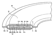
上記説明では、何れも環状中芯体が複数(3層)の環状部材にて構成されている態様を示したが、本発明に係るフッ素樹脂包みガスケットは、上記態様に限定されず、その環状中芯体は、例えば、図6、図7に示すように1層(1枚)の環状部材68,78から構成されていてもよい。すなわち、図6には、図1に示す3層構成の環状中芯体14に代えて、1枚の環状部材68からなる環状中芯体64がフッ素樹脂外被62の環状溝69内に嵌入された態様が示されている。また、図7には、図4に示す3層構成の環状中芯体44に代えて、1枚の環状部材78からなる環状中芯体74がフッ素樹脂外被72の環状溝79内に嵌入された態様が示されている。このような環状部材(環状中芯体)では、その外被側表裏面に硫酸バリウムに代表される無機粉体が偏在していてもよい(図示せず)。
In the above description, an embodiment in which the annular core is composed of a plurality of (three layers) annular members has been shown. However, the fluororesin-wrapped gasket according to the present invention is not limited to the above-described embodiment, and For example, as shown in FIGS. 6 and 7, the core body may be composed of one layer (one sheet) of
これら環状部材68,78の材料は、前記図1等における環状部材18a、18b等とその厚みの点を除いて同一である。以上詳述したように、本発明では、フッ素樹脂包みガスケットの環状中芯材を構成する環状部材は、有機繊維、非石綿系無機繊維、無機粉体(好ましくは硫酸バリウム)、およびバインダーを含んでなっているため、環境への安全性に優れ、圧壊特性に優れている。該環状部材を環状中芯材用の構成材として1枚(1層)以上組み込んだ本発明のフッ素樹脂包みガスケットでは、常温で使用する場合には勿論のこと、高温(200℃程度)で使用する場合にも応力緩和がほとんど増加せず、適度の柔軟性を有し、気密性が良好に保持され、高温での使用にも耐えることができる。
The materials of these
これに対して非石綿フェルト材を中芯材として使用した従来の非石綿系フッ素樹脂包みガスケットにおいては、圧壊現象が顕著であった。その原因は、次のように考えられる。従来、フッ素樹脂包みガスケットに用いられていた石綿フェルト材は、石綿繊維に少量のゴムバインダーを配合したものであって、石綿繊維は繊維径が小さく、それぞれの繊維が縮れて複雑に絡み合った形態であるため、比較的強度が高かった。 On the other hand, in the conventional non-asbestos-based fluororesin-wrapped gasket using a non-asbestos felt material as a core material, the crushing phenomenon was remarkable. The cause is considered as follows. Traditionally, asbestos felt material used for fluororesin-wrapped gaskets is a mixture of asbestos fibers with a small amount of rubber binder, and the asbestos fibers have a small fiber diameter and each fiber is shrunk and intricately intertwined. Therefore, the strength was relatively high.
これに対して、石綿フェルト材に代わる、中芯部材用の非石綿フェルト材としては、従来、無機繊維を主成分とし、無機系粉体と少量の有機バインダーが配合されたものが使われていた。すなわち、従来の石綿フェルト材の配合成分のうち、石綿繊維を、無機粉体と無機繊維とで置き換えたものである。 In contrast, non-asbestos felt materials for core members that replace asbestos felt materials have heretofore been composed of inorganic fibers as the main component, blended with inorganic powder and a small amount of organic binder. It was. That is, asbestos fiber is replaced with inorganic powder and inorganic fiber among the blended components of the conventional asbestos felt material.
しかしながらこれらの非石綿フェルト材は、一般的に剛直で径の大きい無機繊維と、無機粉体とが主体となるため、これらの非石綿フェルト材は、繊維同士のからみ合いが少なく、強度が低い。 However, since these non-asbestos felt materials are mainly composed of rigid and large-diameter inorganic fibers and inorganic powders, these non-asbestos felt materials have little entanglement between fibers and low strength. .
本発明によれば、常温での圧壊特性と高温下の気密特性に優れたフッ素樹脂包みガスケットが提供される。 ADVANTAGE OF THE INVENTION According to this invention, the fluororesin wrapped gasket excellent in the crushing characteristic at normal temperature and the airtight characteristic under high temperature is provided.
本発明に係るフッ素樹脂包みガスケット用中芯材(非石綿系フェルト材)、該中芯材用の環状部材は、常温での圧壊特性と高温下の気密特性に優れている。特に、上記フッ素樹脂包みガスケットにおいて、外被材料として、変性PTFEや、不安定末端基量が低減されており−CF3 末端基のみからなるPFA樹脂などを用いることで、フッ素樹脂包みガスケットにおいては外被破壊強度が向上するだけでなく、中芯材の圧壊強度も向上し、ガスケット締め付け時の過剰締め付けに対する安全性も改善されており、しかも、高温の管体内部流体の流通、遮断の繰り返し等に伴う圧力サイクルに対する耐屈曲性や高温下でのシール保持特性も著しく改善される。 The core material (non-asbestos-based felt material) for a fluororesin-wrapped gasket according to the present invention and the annular member for the core material are excellent in crushing characteristics at normal temperature and airtight characteristics at high temperature. In particular, in the above fluororesin-wrapped gasket, by using a modified PTFE or a PFA resin having a reduced amount of unstable end groups and having only -CF3 end groups as the jacket material, Not only is the fracture strength improved, the crushing strength of the core material has also been improved, the safety against over-tightening when tightening the gasket has been improved, and the flow of fluid inside the pipe body at high temperatures, repeated shut-off, etc. As a result, the bending resistance to pressure cycles and the seal retention characteristics at high temperatures are significantly improved.
特に環状中芯材表面(フェルト面)に無機粉体、好ましくは硫酸バリウムが偏在しているフッ素樹脂包みガスケットでは、高温時における、気密性能が高くなる。 In particular, a fluororesin-wrapped gasket in which inorganic powder, preferably barium sulfate is unevenly distributed on the surface of the annular core material (felt surface) has high airtightness performance at high temperatures.
以下、本発明について実施例に基づき、さらに具体的に説明するが、本発明はかかる実施例により何ら限定されるものではない。 EXAMPLES Hereinafter, although this invention is demonstrated more concretely based on an Example, this invention is not limited at all by this Example.
<圧壊応力(乾燥時)の測定法>
試料ガスケットをフランジ間に装着し、ガスケット応力が10MPaとなるように油圧式圧縮試験機で荷重を負荷し5分間荷重を保持した。その後ガスケットを取り出し、中芯材の表面に微少な亀裂が発生していないかを目視によって確認した。その後ガスケット応力を5MPaごとに上げていき、中芯表面に微少亀裂が発生するまでガスケット応力を上げながら上記確認試験を繰り返した。
<Measurement method of crushing stress (when dry)>
A sample gasket was mounted between the flanges, and a load was applied with a hydraulic compression tester so that the gasket stress was 10 MPa, and the load was maintained for 5 minutes. Thereafter, the gasket was taken out, and it was visually confirmed whether or not a minute crack was generated on the surface of the core material. Thereafter, the gasket stress was increased every 5 MPa, and the above confirmation test was repeated while increasing the gasket stress until a minute crack was generated on the surface of the core.
<圧壊応力(湿潤時)の測定法>
湿潤時の圧壊測定は、ガスケットをあらかじめ24時間水中に浸漬しておくほかは、乾燥時の圧壊測定と同じである。
<Method of measuring crushing stress (when wet)>
The crushing measurement when wet is the same as the crushing measurement when drying, except that the gasket is immersed in water for 24 hours in advance.
[実施例1]
外被材料として一般的に用いられるPTFE(商品名「ポリフロンM12」、ダイキン工業(株))を使用し、中芯材として下記3層構成の非石綿中芯を使用し、ガスケット寸法:「JIS 10K 100A」のフッ素樹脂包みガスケットを製造した(図1)。
[Example 1]
PTFE (trade name “Polyflon M12”, Daikin Industries, Ltd.), which is generally used as the jacket material, is used, and the following three-layer non-asbestos core is used as the core material. Gasket dimensions: “JIS” A 10K 100A "fluororesin-wrapped gasket was manufactured (FIG. 1).
各層の厚さは以下の通り。外被:0.4mm厚中芯:環状部材/ジョイントシート/環状部材=0.8mm/0.8mm/0.8mmの3層構成、中芯全体の厚み2.4mm
(イ)2枚の環状部材:
(1)耐熱性有機繊維(アラミド繊維、商品名「コーネックス」(帝人(株)製)
(2)無機繊維(ロックウール、商品名「エスファイバー繊維」(新日鐵化学(株)製)
(3)無機粉末(硫酸バリウム、平均粒径0.1〜0.2μm)
(4)バインダー(NBRラテックス)
(1)/(2)/(3)/(4)の配合比(重量部)=20/50/26/4
(ロ)ジョイントシート(アラミド繊維10重量%/ゴム40重量%/無機充填剤50重量%、厚み0.8mm)上記フッ素樹脂包みガスケットを複数個作成した。フッ素樹脂包みガスケットを、フランジ(フランジ材質:「SUS 304」、フランジ表面粗さ:Rmax18〜25μm)に取り付け、種々のガスケット面圧を印加して各面圧毎に5分間保持した後に取り出し、中芯材の表面に微少な亀裂が発生した面圧をもって、中芯圧壊面圧とした。
The thickness of each layer is as follows. Outer coating: 0.4 mm thick Core: annular member / joint sheet / annular member = 0.8 mm / 0.8 mm / 0.8 mm three-layer structure, thickness of the entire core 2.4 mm
(A) Two annular members:
(1) Heat-resistant organic fiber (aramid fiber, trade name "Conex" (manufactured by Teijin Limited)
(2) Inorganic fiber (rock wool, trade name “S Fiber Fiber” (manufactured by Nippon Steel Chemical Co., Ltd.)
(3) Inorganic powder (barium sulfate, average particle size 0.1 to 0.2 μm)
(4) Binder (NBR latex)
(1) / (2) / (3) / (4) (ratio by weight) = 20/50/26/4
(B) Joint sheet (
得られたフッ素樹脂包みガスケットの中芯圧壊面圧は、乾燥時120MPa、湿潤時100MPaとなった。結果を併せて表1に示す。 The core collapse surface pressure of the obtained fluororesin-wrapped gasket was 120 MPa when dried and 100 MPa when wet. The results are also shown in Table 1.
また、上記と同様のフランジにこのフッ素樹脂包みガスケットを取り付け、気密内圧(200℃で100時間加熱後、窒素ガスを加圧して測定)を測定したところ、3.5MPaとなった。 Further, this fluororesin-wrapped gasket was attached to the same flange as described above, and the hermetic internal pressure (measured by applying nitrogen gas after heating at 200 ° C. for 100 hours) was 3.5 MPa.
[実施例2]
外被材料として変性PTFE(商品名「ポリフロンM−112」、ダイキン工業(株))を使用した以外は実施例1と同様にしてフッ素樹脂包みガスケットを製造した。
[Example 2]
A fluororesin-wrapped gasket was produced in the same manner as in Example 1 except that modified PTFE (trade name “Polyflon M-112”, Daikin Industries, Ltd.) was used as the jacket material.
その結果、実施例2で得られたフッ素樹脂包みガスケットの中芯圧壊面圧は、乾燥時130MPa、湿潤時120MPaとなった。また、気密内圧は、3.0MPaとなった。
結果を併せて表1に示す。
As a result, the core collapse surface pressure of the fluororesin-wrapped gasket obtained in Example 2 was 130 MPa when dried and 120 MPa when wet. The airtight internal pressure was 3.0 MPa.
The results are also shown in Table 1.
[比較例1]
実施例1において、配合組成を表1に示すようにロックウール65重量部、セピオライト31重量部、バインダー4重量部に代えた以外は、実施例1と同様にしてフッ素樹脂包みガスケットを作成した。
[Comparative Example 1]
In Example 1, a fluororesin-wrapped gasket was prepared in the same manner as in Example 1 except that the composition was changed to 65 parts by weight of rock wool, 31 parts by weight of sepiolite, and 4 parts by weight of binder as shown in Table 1.
得られたフッ素樹脂包みガスケットの圧壊応力(乾燥時)は、70MPa、圧壊応力(湿潤時)は40MPaとなった。また、上記と同様のフランジにこのフッ素樹脂包みガスケットを取り付け、気密内圧(200℃で100時間加熱後、窒素ガスを加圧して測定)を測定したところ、3.0MPaとなった。
結果を併せて表1に示す。
The obtained fluororesin-wrapped gasket had a crushing stress (when dried) of 70 MPa and a crushing stress (when wet) of 40 MPa. Further, this fluororesin-wrapped gasket was attached to the same flange as described above, and the hermetic internal pressure (measured by applying nitrogen gas after heating at 200 ° C. for 100 hours) was 3.0 MPa.
The results are also shown in Table 1.
[比較例2]
実施例1において、配合組成を表1に示すように石綿繊維80重量部、セピオライト16重量部、バインダー4重量部に代えた以外は、実施例1と同様にしてフッ素樹脂包みガスケットを作成した。
[Comparative Example 2]
In Example 1, as shown in Table 1, a fluororesin-wrapped gasket was prepared in the same manner as in Example 1 except that asbestos fiber was replaced by 80 parts by weight,
得られたフッ素樹脂包みガスケットの圧壊応力(乾燥時)は、110MPa、圧壊応力(湿潤時)は60MPaとなった。また、上記と同様のフランジにこのフッ素樹脂包みガスケットを取り付け、気密内圧(200℃で100時間加熱後、窒素ガスを加圧して測定)を測定したところ、3.0MPaとなった。
結果を併せて表1に示す。
The resulting fluororesin-wrapped gasket had a crushing stress (when dried) of 110 MPa and a crushing stress (when wet) of 60 MPa. Further, this fluororesin-wrapped gasket was attached to the same flange as described above, and the hermetic internal pressure (measured by applying nitrogen gas after heating at 200 ° C. for 100 hours) was 3.0 MPa.
The results are also shown in Table 1.

5・・・・・環状溝奥部
6・・・・・環状溝奥部の鋭角部
6c・・・・・環状溝奥部の最奥部
10、20、30、40、50、60、70・・・・・フッ素樹脂包みガスケット
11a、21a、31a、41a、51a、61a、71a・・・・・環状部材の上部外被側面(表面)
11b、21b、31b、41b、51b、61b、71b・・・・・環状部材の下部外被側面(表面)
12、22、32、42、52、62、72・・・・・フッ素樹脂外被
12a、22a、32a、42a、52a、62a、72a・・・・・下側フッ素樹脂外被(下部外被)
12b、22b、32b、42b、52b、62b・・・・・上側フッ素樹脂外被(上部外被)
13a、23a、33a、43a、53a、63a・・・・・環状部材あるいは環状中芯体の外被側面(表面)
13b、23b、33b、43b、53b、63b、73b・・・・・環状部材あるいは環状中芯体の外被側面(表面)
14、24、34、44、54、64、74・・・・・環状中芯体
15b・・・・・ガスケットの外径側端部
16、26、36、46、56・・・・・環状シート(ジョイントシート)
27・・・・・無機粉体が外被側表面に偏在した環状部材
27a、28a・・・・・有機繊維、無機繊維およびバインダーを主成分とする層
28・・・・・無機粉体が外被側表面に偏在した環状部材
27b、28b・・・・・無機粉体(硫酸バリウム)とバインダーを主成分 とする層
18a、38a、48a、58a、68a、78a・・・・・環状部材(下面側環状部材)
18b、38b、48b、58b、68b、78b・・・・・環状部材(上面側環状部材)
19、29、39、49、59、69、79・・・・・環状溝
55a・・・・・フッ素樹脂外被の内径側端部
15b、25b、35b、45b、55b・・・・・フッ素樹脂外被あるいはガスケットの外径側端部
5: Annular groove depth 6: An acute angle part 6c: Annular groove depth: 10, 20, 30, 40, 50, 60, 70 ...... Fluoropolymer-wrapped
11b, 21b, 31b, 41b, 51b, 61b, 71b...
12, 22, 32, 42, 52, 62, 72...
12b, 22b, 32b, 42b, 52b, 62b ... Upper fluororesin jacket (upper jacket)
13a, 23a, 33a, 43a, 53a, 63a ... The outer side surface (surface) of the annular member or annular core
13b, 23b, 33b, 43b, 53b, 63b, 73b ... The outer side surface (surface) of the annular member or annular core
14, 24, 34, 44, 54, 64, 74 ...
27... An annular member in which inorganic powder is unevenly distributed on the outer surface side 27 a, 28 a... Layer mainly composed of organic fiber, inorganic fiber and
18b, 38b, 48b, 58b, 68b, 78b ... annular member (upper surface side annular member)
19, 29, 39, 49, 59, 69, 79... Annular groove 55a... Inner diameter side end portion of
Claims (6)
前記環状部材が、有機繊維、無機繊維、無機粉体およびバインダーを含み、
前記環状シートがゴム板、コルク板およびジョイントシート材からなる群より選ばれる少なくとも1種から構成され、
前記無機粉体が環状部材中に一様に分散していることを特徴とするフッ素樹脂包みガスケット。 A fluororesin-wrapped gasket in which an annular core, an annular sheet and an annular member are laminated in this order in an annular groove of the fluororesin jacket,
The annular member includes organic fiber, inorganic fiber, inorganic powder and binder,
The annular sheet is composed of at least one selected from the group consisting of a rubber plate, a cork plate and a joint sheet material,
A fluororesin-wrapped gasket, wherein the inorganic powder is uniformly dispersed in an annular member.
前記環状部材が、有機繊維、無機繊維、無機粉体およびバインダーを含み、
前記環状シートがゴム板、コルク板およびジョイントシート材からなる群より選ばれる少なくとも1種から構成され、
前記無機粉体が環状部材中に、前記フッ素樹脂外被側表面に偏在していることを特徴とするフッ素樹脂包みガスケット。 A fluororesin-wrapped gasket in which an annular core, an annular sheet and an annular member are laminated in this order in an annular groove of the fluororesin jacket,
The annular member includes organic fiber, inorganic fiber, inorganic powder and binder,
The annular sheet is composed of at least one selected from the group consisting of a rubber plate, a cork plate and a joint sheet material,
A fluororesin-wrapped gasket, wherein the inorganic powder is unevenly distributed on the surface of the fluororesin jacket side in an annular member.
Priority Applications (1)
| Application Number | Priority Date | Filing Date | Title |
|---|---|---|---|
| JP2008208970A JP5155771B2 (en) | 2008-08-14 | 2008-08-14 | Fluoropolymer-wrapped gasket |
Applications Claiming Priority (1)
| Application Number | Priority Date | Filing Date | Title |
|---|---|---|---|
| JP2008208970A JP5155771B2 (en) | 2008-08-14 | 2008-08-14 | Fluoropolymer-wrapped gasket |
Related Parent Applications (1)
| Application Number | Title | Priority Date | Filing Date |
|---|---|---|---|
| JP10274878A Division JP2000104832A (en) | 1998-09-29 | 1998-09-29 | Gasket coated with fluororesin |
Publications (2)
| Publication Number | Publication Date |
|---|---|
| JP2009024877A JP2009024877A (en) | 2009-02-05 |
| JP5155771B2 true JP5155771B2 (en) | 2013-03-06 |
Family
ID=40396847
Family Applications (1)
| Application Number | Title | Priority Date | Filing Date |
|---|---|---|---|
| JP2008208970A Expired - Lifetime JP5155771B2 (en) | 2008-08-14 | 2008-08-14 | Fluoropolymer-wrapped gasket |
Country Status (1)
| Country | Link |
|---|---|
| JP (1) | JP5155771B2 (en) |
Families Citing this family (5)
| Publication number | Priority date | Publication date | Assignee | Title |
|---|---|---|---|---|
| JP5253273B2 (en) * | 2009-04-02 | 2013-07-31 | 日本バルカー工業株式会社 | Fluororesin sheet, method for producing the same, and gasket |
| US20110287677A1 (en) | 2010-05-19 | 2011-11-24 | Garlock Sealing Technologies, Llc | Flexible reinforced gasket |
| BR112013009832B1 (en) * | 2010-10-20 | 2020-12-15 | Garlock Sealing Technologies, Llc | EXTREME TEMPERATURE SEALING MATERIAL |
| JP2013161904A (en) * | 2012-02-03 | 2013-08-19 | Nok Corp | Electromagnetic wave shield gasket and manufacturing method therefor |
| WO2020066347A1 (en) * | 2018-09-28 | 2020-04-02 | 株式会社巴川製紙所 | Seal material for analytical instrument, and flow cell, detection instrument, and analytical instrument using said seal material |
Family Cites Families (5)
| Publication number | Priority date | Publication date | Assignee | Title |
|---|---|---|---|---|
| JPS4729856Y1 (en) * | 1967-02-17 | 1972-09-07 | ||
| JPS574746A (en) * | 1980-05-27 | 1982-01-11 | Nichias Corp | Gasket covered by fluorine-contained resin |
| JP2581010Y2 (en) * | 1990-07-27 | 1998-09-17 | 日本バルカー工業株式会社 | Fluoroplastic wrapped gasket |
| JP3006624B2 (en) * | 1990-09-28 | 2000-02-07 | 日本バルカー工業株式会社 | Joint sheet |
| JPH07286164A (en) * | 1994-02-23 | 1995-10-31 | Nippon Valqua Ind Ltd | Joint sheet |
-
2008
- 2008-08-14 JP JP2008208970A patent/JP5155771B2/en not_active Expired - Lifetime
Also Published As
| Publication number | Publication date |
|---|---|
| JP2009024877A (en) | 2009-02-05 |
Similar Documents
| Publication | Publication Date | Title |
|---|---|---|
| JP5155771B2 (en) | Fluoropolymer-wrapped gasket | |
| US10851919B2 (en) | Fire resistant flexible hose | |
| US5421594A (en) | Gasket | |
| US5551706A (en) | Composite gasket for sealing flanges and method for making and using same | |
| PL188472B1 (en) | Flat gasket made of laminated plastics | |
| FR2524605A1 (en) | FLEXIBLE PROTECTIVE ELEMENTS AGAINST FIRE, AND OBJECTS COMPRISING SAME, IN PARTICULAR FLEXIBLE PIPING | |
| JP4570897B2 (en) | Gasket for flange joint | |
| EP3638932B1 (en) | Multi-layered ptfe radial lip seal | |
| US20070125438A1 (en) | Flexible tubular pipe, especially for oil production, having a ptfe winding | |
| JP2008007607A (en) | Filler-filled fluororesin sheet and process for producing filler-filled fluororesin sheet | |
| JP2005337401A (en) | Gasket coated with fluororesin | |
| US11426973B2 (en) | High temperature hose | |
| JP2003106456A (en) | Fluororesin covered gasket | |
| JP2000104832A (en) | Gasket coated with fluororesin | |
| US11034124B2 (en) | Insulated conduit including a fluoropolymer composition for use as a thermal insulation layer | |
| JP2006096991A (en) | Ptfe resin molded item, monolithic structure using ptfe resin molded body and their preparation process | |
| JP7235774B2 (en) | Layered Composite for Sealing | |
| JP2000055204A (en) | Manufacture of composite structure o-ring | |
| EP2147236B1 (en) | Fire-resistant seal | |
| JP2008013715A (en) | Method for producing fluoroplastic sheet containing filler and filled fluoroplastic sheet containing filler | |
| WO2019087959A1 (en) | Sealing material | |
| JP2007203604A (en) | Structure adhered with ptfe resin moldings and method for adhering ptfe resin moldings | |
| JP6652321B2 (en) | Fluoroplastic wrapped gasket | |
| GB2391599A (en) | Impovements in multilayered pipes | |
| JPH0115744B2 (en) |
Legal Events
| Date | Code | Title | Description |
|---|---|---|---|
| A131 | Notification of reasons for refusal |
Free format text: JAPANESE INTERMEDIATE CODE: A131 Effective date: 20110823 |
|
| A521 | Written amendment |
Free format text: JAPANESE INTERMEDIATE CODE: A523 Effective date: 20111020 |
|
| RD02 | Notification of acceptance of power of attorney |
Free format text: JAPANESE INTERMEDIATE CODE: A7422 Effective date: 20120223 |
|
| A131 | Notification of reasons for refusal |
Free format text: JAPANESE INTERMEDIATE CODE: A131 Effective date: 20120508 |
|
| A521 | Written amendment |
Free format text: JAPANESE INTERMEDIATE CODE: A523 Effective date: 20120629 |
|
| TRDD | Decision of grant or rejection written | ||
| A01 | Written decision to grant a patent or to grant a registration (utility model) |
Free format text: JAPANESE INTERMEDIATE CODE: A01 Effective date: 20121204 |
|
| A61 | First payment of annual fees (during grant procedure) |
Free format text: JAPANESE INTERMEDIATE CODE: A61 Effective date: 20121207 |
|
| FPAY | Renewal fee payment (event date is renewal date of database) |
Free format text: PAYMENT UNTIL: 20151214 Year of fee payment: 3 |
|
| R150 | Certificate of patent or registration of utility model |
Free format text: JAPANESE INTERMEDIATE CODE: R150 |
|
| R250 | Receipt of annual fees |
Free format text: JAPANESE INTERMEDIATE CODE: R250 |
|
| R250 | Receipt of annual fees |
Free format text: JAPANESE INTERMEDIATE CODE: R250 |
|
| R250 | Receipt of annual fees |
Free format text: JAPANESE INTERMEDIATE CODE: R250 |
|
| EXPY | Cancellation because of completion of term |