JP5155656B2 - Actuator casing - Google Patents
Actuator casing Download PDFInfo
- Publication number
- JP5155656B2 JP5155656B2 JP2007522712A JP2007522712A JP5155656B2 JP 5155656 B2 JP5155656 B2 JP 5155656B2 JP 2007522712 A JP2007522712 A JP 2007522712A JP 2007522712 A JP2007522712 A JP 2007522712A JP 5155656 B2 JP5155656 B2 JP 5155656B2
- Authority
- JP
- Japan
- Prior art keywords
- casing
- actuator casing
- actuator
- valve
- flange
- Prior art date
- Legal status (The legal status is an assumption and is not a legal conclusion. Google has not performed a legal analysis and makes no representation as to the accuracy of the status listed.)
- Active
Links
- XAGFODPZIPBFFR-UHFFFAOYSA-N aluminium Chemical compound [Al] XAGFODPZIPBFFR-UHFFFAOYSA-N 0.000 claims description 35
- 229910052782 aluminium Inorganic materials 0.000 claims description 35
- CWYNVVGOOAEACU-UHFFFAOYSA-N Fe2+ Chemical compound [Fe+2] CWYNVVGOOAEACU-UHFFFAOYSA-N 0.000 claims description 2
- VNWKTOKETHGBQD-UHFFFAOYSA-N methane Chemical compound C VNWKTOKETHGBQD-UHFFFAOYSA-N 0.000 description 20
- 239000007789 gas Substances 0.000 description 14
- 239000012530 fluid Substances 0.000 description 11
- 239000003345 natural gas Substances 0.000 description 10
- 238000000034 method Methods 0.000 description 9
- 239000000463 material Substances 0.000 description 6
- 231100000817 safety factor Toxicity 0.000 description 6
- 229910000831 Steel Inorganic materials 0.000 description 4
- 239000010959 steel Substances 0.000 description 4
- 238000004519 manufacturing process Methods 0.000 description 3
- 238000007789 sealing Methods 0.000 description 3
- 238000004880 explosion Methods 0.000 description 2
- 238000004886 process control Methods 0.000 description 2
- 206010003497 Asphyxia Diseases 0.000 description 1
- 239000000853 adhesive Substances 0.000 description 1
- 230000001070 adhesive effect Effects 0.000 description 1
- 238000005260 corrosion Methods 0.000 description 1
- 230000007797 corrosion Effects 0.000 description 1
- 238000010586 diagram Methods 0.000 description 1
- 239000007788 liquid Substances 0.000 description 1
- 239000000565 sealant Substances 0.000 description 1
Images


Classifications
-
- F—MECHANICAL ENGINEERING; LIGHTING; HEATING; WEAPONS; BLASTING
- F16—ENGINEERING ELEMENTS AND UNITS; GENERAL MEASURES FOR PRODUCING AND MAINTAINING EFFECTIVE FUNCTIONING OF MACHINES OR INSTALLATIONS; THERMAL INSULATION IN GENERAL
- F16K—VALVES; TAPS; COCKS; ACTUATING-FLOATS; DEVICES FOR VENTING OR AERATING
- F16K27/00—Construction of housing; Use of materials therefor
-
- F—MECHANICAL ENGINEERING; LIGHTING; HEATING; WEAPONS; BLASTING
- F16—ENGINEERING ELEMENTS AND UNITS; GENERAL MEASURES FOR PRODUCING AND MAINTAINING EFFECTIVE FUNCTIONING OF MACHINES OR INSTALLATIONS; THERMAL INSULATION IN GENERAL
- F16K—VALVES; TAPS; COCKS; ACTUATING-FLOATS; DEVICES FOR VENTING OR AERATING
- F16K31/00—Actuating devices; Operating means; Releasing devices
- F16K31/12—Actuating devices; Operating means; Releasing devices actuated by fluid
- F16K31/126—Actuating devices; Operating means; Releasing devices actuated by fluid the fluid acting on a diaphragm, bellows, or the like
Description
本願は、流体制御器具に関し、より詳しくは、バルブ本体に配置された流体調整器とともに使用するための鍛造アルミニウム製のアクチュエータケーシングに関するものである。 The present application relates to fluid control instruments and, more particularly, to an actuator casing made of forged aluminum for use with a fluid regulator disposed in a valve body.
本願は、2004年7月23日に出願された米国合衆国仮出願60/590,741の出願日の利益を主張する。 This application claims the benefit of the filing date of US Provisional Application 60 / 590,741, filed July 23, 2004.
プロセス制御プラントまたはプロセス制御システムは、しばしば、例えば、液体、気体などのプロセス流体の流量と圧力を制御するために、流体制御器具(例えば、制御バルブ、圧力調整器など)を使用する。特に重要な流体バルブの利用分野は、天然ガスの分配と搬送に関するものである。一般的に、天然ガスの分配システムの大部分は、比較的高圧で比較的大量のガスを搬送および分配するように形成されている。ガスが比較的高圧で搬送されると、所望のガス容積を搬送するのに必要な流量が減少され、このように、配管による規制やバルブによる規制などによって引き起こされる搬送効率の低下(例えば、圧力損失)を最小にする。 Process control plants or process control systems often use fluid control instruments (eg, control valves, pressure regulators, etc.) to control the flow rate and pressure of process fluids such as liquids, gases, and the like. A particularly important application area for fluid valves relates to the distribution and transport of natural gas. In general, the majority of natural gas distribution systems are configured to convey and distribute a relatively large amount of gas at a relatively high pressure. When the gas is transported at a relatively high pressure, the flow rate required to transport the desired gas volume is reduced, thus reducing the transport efficiency caused by piping restrictions or valve restrictions (for example, pressure Loss).
天然ガス分配システムで使用される流体バルブは、比較的高圧のガスを制御しなければならないことに加えて、その天然ガスの周囲や雰囲気への漏れ量を最小にするか又は漏れがないようにしなければならない。流体バルブから天然ガスが漏れると、例えば、爆発や火災や窒息のような危険な状態に結び付くことになる。 In addition to having to control relatively high pressure gases, fluid valves used in natural gas distribution systems minimize or eliminate leaks to and from the natural gas. There must be. Leakage of natural gas from the fluid valve can lead to dangerous conditions such as explosions, fires and suffocation.
このように、流体バルブ本体を通る天然ガスの流量を制御するために使用されるアクチュエータは、天然ガスの分配に伴う高圧に耐えるように設計しなければならない。さらに、そのアクチュエータは、たとえ漏れることがあったとしても、周囲には殆どガスが漏れないようにしなければならない。その結果、アクチュエータのために使用されるケーシングは、一般的に高強度であって、周囲へのガスの漏れ量が最小であるか、又は漏れがないように設計される。 Thus, the actuators used to control the flow of natural gas through the fluid valve body must be designed to withstand the high pressures associated with natural gas distribution. In addition, the actuator must be such that almost no gas leaks around, even if it may leak. As a result, casings used for actuators are generally designed to be high strength and have minimal or no leakage of gas to the surroundings.
天然ガス制御器具(例えば、減圧調整器)とともに使用されるいくらかのアクチュエータケーシングは、鍛造鋼ケーシング半割体を使用している。鋼のアクチュエータケーシングは比較的高強度であって、比較的長い間、極めて高い圧力にも耐えることができる。さらに、鋼のアクチュエータケーシングは実質的に非多孔質であるから、その結果、ガスが周囲に漏れないように制御する必要がない。ところが、鋼のアクチュエータケーシングは極めて安全で、幅広い制御圧にわたって性能が信頼できる一方、極めて価格が高く、多くの低圧ガスの分配に使用するには重すぎる。例えば、天然ガス分配システムにおける天然ガスの制御は、一般的に、搬送箇所または使用箇所の近くでは低圧にする必要がある。 Some actuator casings used with natural gas control instruments (eg, vacuum regulators) use forged steel casing halves. The steel actuator casing is relatively strong and can withstand very high pressures for a relatively long time. In addition, the steel actuator casing is substantially non-porous, so that there is no need to control the gas so that it does not leak out. However, while steel actuator casings are extremely safe and reliable in performance over a wide range of control pressures, they are extremely expensive and too heavy to use for the distribution of many low pressure gases. For example, control of natural gas in a natural gas distribution system generally requires a low pressure near the point of transportation or use.
鋳造アルミニウム製のアクチュエータケーシングは、ガス分配システム内で低圧ガスを制御する流体バルブを提供するために使用される。鋳造アルミニウム製のアクチュエータケーシングは比較的安価であるが、一般に多孔質であって、ケーシングの壁に割れ目がある。孔や割れ目があると、使用するために高い安全ファクター(すなわち、作動圧力に対する最大圧力比または爆発圧力比を大きくすること)を必要とし、壁の厚みも大きくする必要がある。いくらかの鋳造アルミニウム製のアクチュエータケーシングは、4から1もの高い安全ファクターを必要とする。壁の厚みが大きくなると、より多くの材料を必要とし、鋳造アルミニウム製のアクチュエータケーシングの重量とコストを増大させてしまう。 An actuator casing made of cast aluminum is used to provide a fluid valve that controls the low pressure gas within the gas distribution system. Cast aluminum actuator casings are relatively inexpensive, but are generally porous and have cracks in the casing walls. If there are holes or cracks, a high safety factor (ie, increasing the maximum pressure ratio or explosion pressure ratio relative to the operating pressure) is required for use, and the wall thickness needs to be increased. Some cast aluminum actuator casings require safety factors as high as 4 to 1. Increasing the wall thickness requires more material and increases the weight and cost of the cast aluminum actuator casing.
さらに、鋳造アルミニウム製のアクチュエータケーシングの孔は、二次加工プロセスにより密封されるべき半割体が必要である。よく知られたプロセスは、例えば、接着剤または密封剤を鋳造アルミニウム製のアクチュエータケーシング半割体に充填する方法である。しかし、そのような二次加工プロセスはコストが高くつき、生産量の減少に結びつきやすい(すなわち、搬送バルブを使用するいくらかの部分は十分に密封することができない)。 Furthermore, the hole in the cast aluminum actuator casing requires a half body to be sealed by the secondary processing process. A well-known process is, for example, a method of filling a cast aluminum actuator casing half with an adhesive or sealant. However, such secondary processing processes are costly and tend to reduce production (i.e., some parts that use the transfer valve cannot be adequately sealed).
本発明は、低コストで重量が軽く、安全性と生産性に優れたアクチュエータケーシングを提供することにある。 An object of the present invention is to provide an actuator casing that is low in cost, light in weight, and excellent in safety and productivity.
本発明の鍛造アルミニウム製のアクチュエータケーシングは、一般的な鋳造アルミニウム製のアクチュエータケーシングに比べて、相当軽量化しうる。特に、本発明の鍛造アルミニウム製のアクチュエータケーシングを製造するために使用される材料と加工技術によれば、実質的に非多孔質で非鉄製で、鋳造アルミニウム製のアクチュエータケーシングより実質的に延性があるケーシングを提供できる。本発明の鍛造アルミニウム製のアクチュエータケーシングの実質的な延性は(非多孔質の特性とともに)、設計上の安全ファクター(すなわち、アクチュエータケーシングの作動圧力に対する最大安全圧力の比)を相当量低減する。 The actuator casing made of forged aluminum according to the present invention can be considerably reduced in weight as compared with a general actuator casing made of cast aluminum. In particular, the materials and processing techniques used to produce the forged aluminum actuator casing of the present invention are substantially non-porous, non-ferrous and substantially more ductile than cast aluminum actuator casings. A casing can be provided. The substantial ductility of the forged aluminum actuator casing of the present invention (along with non-porous properties) significantly reduces the design safety factor (ie, the ratio of the maximum safe pressure to the operating pressure of the actuator casing).
例えば、鋳造アルミニウム製のアクチュエータケーシングを設計するとき、一般的には、約4ないし1の安全ファクターが使用される。しかし、本発明の鍛造アルミニウム製のアクチュエータケーシングは約1.5ないし1の安全ファクターを使用することができる。 For example, when designing cast aluminum actuator casings, a safety factor of about 4 to 1 is typically used. However, the forged aluminum actuator casing of the present invention can use a safety factor of about 1.5 to 1.
本発明の鍛造アルミニウム製のアクチュエータケーシングにおける低い安全ファクターによれば、鋳造アルミニウム製のアクチュエータケーシングに比べて相当壁の厚みが薄いアルミニウム製のアクチュエータケーシングを製造することができる。壁の厚みが薄くなると、性能が同等の鋳造アルミニウム製のアクチュエータケーシングに比べて相当使用材料が少なくてすむ(相当重量が軽くなる)アクチュエータケーシングを提供できる。鋳造アルミニウム製のアクチュエータケーシングに比べて重量が軽くなるということのほかに、本発明の鍛造アルミニウム製のアクチュエータケーシングは、実質的に非多孔質であり、(公知の鋳造アルミニウム製のアクチュエータケーシングについて一般的に使用されているような)二次的密封加工プロセスは必要とされない。 According to the low safety factor of the forged aluminum actuator casing of the present invention, it is possible to produce an aluminum actuator casing having a considerably thinner wall than a cast aluminum actuator casing. When the wall thickness is reduced, it is possible to provide an actuator casing that requires a relatively small amount of material (equivalent weight is reduced) compared to a cast aluminum actuator casing having the same performance. In addition to being lighter in weight than cast aluminum actuator casings, the forged aluminum actuator casings of the present invention are substantially non-porous and are commonly used for known cast aluminum actuator casings. No secondary sealing process (such as is commonly used) is required.
さらに、本発明の鍛造アルミニウム製のアクチュエータケーシングは、金属および合金用の統一番号システム(UNS)の標準A92014アルミニウムで形成される、アメリカ合衆国機械学会(ASME)の標準SB247CL.T4に従う材料を使用して製造することができる。そのように、ASMEに従う材料を使用することで、世界中の多くの市場における鍛造アルミニウム製のアクチュエータを使用する利用分野における承認プロセスを大いに単純化することができる。例えば、上記の材料(すなわち、ASMESB247CL.T4)はASMEボイラーコードに合致するものであり、本発明の鍛造アルミニウム製のアクチュエータケーシングの承認プロセスを大いに単純化する。 In addition, the actuator casing made of forged aluminum of the present invention is made from the American Society of Mechanical Engineers (ASME) standard SB247CL. It can be manufactured using materials according to T4. As such, using materials in accordance with ASME can greatly simplify the approval process in applications using actuators made of forged aluminum in many markets around the world. For example, the above material (ie ASMESB247CL.T4) is compatible with ASME boiler code and greatly simplifies the approval process for the forged aluminum actuator casing of the present invention.
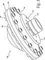
図1には、流体バルブとともに使用するための参照番号100で指し示す鍛造アルミニウム製のアクチュエータケーシングの一実施例が示されている。鍛造アルミニウム製のアクチュエータケーシング100は、上部アクチュエータケーシング半割体102と下部アクチュエータケーシング半割体104を有している。用語「上部」と「下部」は、アクチュエータケーシング100の2個の半割体を識別するためだけに使用されるものであり、アクチュエータケーシング100が使用される方法を限定することを意図したものではない。例えば、アクチュエータケーシング100は、特別の分野での必要性を満たすように、好ましい向きに装着することができる。以下、アクチュエータケーシング半割体102と104は、それぞれ、「上部アクチュエータケーシング半割体」および「下部アクチュエータケーシング半割体」と呼ぶことにする。
FIG. 1 shows one embodiment of a forged aluminum actuator casing, designated by
上部アクチュエータケーシング半割体102と下部アクチュエータケーシング半割体104は、締結具110を介してフランジ部分106と108において密封して連結されている。締結具110は、例えば、ナット、ボルト、座金のような適切な締結メカニズムである。
The upper
下部アクチュエータケーシング半割体104は、図2に示すように、アクチュエータケーシング100をバルブ本体に(例えば、ボルトにより)固定することができる装着フランジ部分112を有している。装着フランジ部分112は、アクチュエータケーシング100を複数の異なるバルブ本体のいずれかの部分に固定することができる孔または開口のパターン114を有している。下部アクチュエータケーシング半割体104は、また、図2に詳細に示すように、アクチュエータケーシング100とバルブ本体の位置を調整して連結し、バルブトリムの作動をガイドし、アクチュエータケーシング100がバルブ本体を密封してシールすることを容易にするハブ部分116を有している。
As shown in FIG. 2, the lower
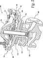
図2は、図1において参照番号100で指し示す鍛造アルミニウム製のアクチュエータケーシングの一実施例を使用するガスバルブ200の一実施例の断面図である。図2は、アクチュエータケーシング100、バルブ本体202およびバルブトリム204の間の関係を示している。バルブ本体202およびバルブトリム204は、公知または他の適当なバルブ本体およびバルブトリムからなるものであり、本明細書においてはさらに記載しない。図2に示すように、ダイアフラム206およびダイアフラム板208は、アクチュエータケーシング100内に配置されている。
FIG. 2 is a cross-sectional view of one embodiment of a gas valve 200 that uses one embodiment of a forged aluminum actuator casing indicated by
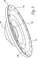
図3は、図1において参照番号100で指し示す鍛造アルミニウム製のアクチュエータケーシングの一実施例の上部アクチュエータケーシング半割体102を示している。図3に示すように、上部アクチュエータケーシング半割体102は、フランジ部分106の周縁部に離間して配置された複数の開口302を有している。第一アングル壁部分304は、フランジ部分106と肩部分306の間にわたって伸びている。肩部分306は、ダイアフラム板208および/又はダイアフラム206をサポートおよび/又は停止することができる機械的サポートまたは機械的ストッパとして作用する。第一アングル壁部分304の深さおよび角度は、ダイアフラム206の好ましい作動範囲を得、および/又はアクチュエータケーシング100の使用中にダイアフラム206に付加される応力を制御するように選択することができる(図1参照)。上部アクチュエータケーシング半割体102は、また、バルブトリム204および/又は偏倚スプリング(図示せず)の作動をガイドするために使用されるハブ308を有している。
FIG. 3 shows an upper
図4は、図3の上部アクチュエータケーシング半割体102の平面図であり、図5は、図3の上部アクチュエータケーシング半割体102の断面図である。
4 is a plan view of the upper
図6は、図1において参照番号100で指し示す鍛造アルミニウム製のアクチュエータケーシングの一実施例の下部アクチュエータケーシング半割体104を示している。下部アクチュエータケーシング半割体104は、図1に示す締結具110を受け入れることができる複数の開口602を有している。
FIG. 6 shows a lower
図7は、図6の下部アクチュエータケーシング半割体104の平面図であり、図8は、図6の下部アクチュエータケーシング半割体104の断面図である。
FIG. 7 is a plan view of the lower
例えば、修理に利用する場合、上部アクチュエータケーシング半割体102と下部アクチュエータケーシング半割体104は、腐食などからそのアクチュエータケーシング半割体102と104を保護するために陽極処理が施される。
For example, when used for repair, the upper
本発明の物品、その製造方法、及びその製造装置の実施例を説明したが、本発明の技術的範囲は上記実施例に限定されるものではない。特許請求の範囲に記載された文言どおりのもの及びその文言と均等なものは、本発明の技術的範囲に含まれる。 Although the embodiments of the article of the present invention, the manufacturing method thereof, and the manufacturing apparatus thereof have been described, the technical scope of the present invention is not limited to the above embodiments. What is literally described in the claims and equivalents thereof are included in the technical scope of the present invention.
100 アクチュエータケーシング
102 上部アクチュエータケーシング半割体
104 下部アクチュエータケーシング半割体
106 フランジ部分
108 フランジ部分
110 締結具
112 装着フランジ部分
114 孔または開口のパターン
116 ハブ部分
200 ガスバルブ
202 バルブ本体
204 バルブトリム
206 ダイアフラム
208 ダイアフラム板
302 開口
304 第一アングル壁部分
306 肩部分
308 ハブ
602 開口
DESCRIPTION OF
Claims (6)
鍛造アルミニウム製の第一ケーシング部分、
鍛造アルミニウム製の第二ケーシング部分、および、
当該第一ケーシング部分と当該第二ケーシング部分とを連結する少なくとも一つの締結具を含み、
少なくとも一つの開口を備えた第一フランジが、当該第一ケーシング部分の周りに備えられており、
少なくとも一つの開口を備えた第二フランジが、当該第二ケーシング部分の周りに備えられており、
当該締結具が、当該第一フランジおよび当該第二フランジの各々が有する開口を介して、当該第一ケーシング部分と当該第二ケーシング部分とを連結し、
当該第一ケーシング部分と当該第二ケーシング部分とが連結された時に、当該アクチュエータケーシングは、1を超え、かつ2未満の安全ファクターを有し、および、
当該第一ケーシング部分および当該第二ケーシング部分は、密封して連結されている、ことを特徴とするアクチュエータケーシング。A non-porous, non-ferrous actuator casing for use with a valve,
First casing part made of forged aluminum,
A second casing part made of forged aluminum, and
Including at least one fastener connecting the first casing portion and the second casing portion ;
A first flange with at least one opening is provided around the first casing part;
A second flange with at least one opening is provided around the second casing part;
The fastener connects the first casing part and the second casing part through the openings of the first flange and the second flange,
Sometimes a said first housing portion and said second casing portions are coupled, the actuator casing is greater than 1, and has less than two safety factor, and,
It said first casing portion and said second housing portion, sealed and are connected, the actuator casing, wherein.
Applications Claiming Priority (3)
| Application Number | Priority Date | Filing Date | Title |
|---|---|---|---|
| US59074104P | 2004-07-23 | 2004-07-23 | |
| US60/590,741 | 2004-07-23 | ||
| PCT/US2005/025781 WO2006014763A1 (en) | 2004-07-23 | 2005-07-20 | Actuator casing |
Publications (2)
| Publication Number | Publication Date |
|---|---|
| JP2008507670A JP2008507670A (en) | 2008-03-13 |
| JP5155656B2 true JP5155656B2 (en) | 2013-03-06 |
Family
ID=35044854
Family Applications (1)
| Application Number | Title | Priority Date | Filing Date |
|---|---|---|---|
| JP2007522712A Active JP5155656B2 (en) | 2004-07-23 | 2005-07-20 | Actuator casing |
Country Status (12)
| Country | Link |
|---|---|
| US (1) | US20060022163A1 (en) |
| EP (1) | EP1779012B1 (en) |
| JP (1) | JP5155656B2 (en) |
| CN (1) | CN1985117A (en) |
| AR (1) | AR050357A1 (en) |
| AU (1) | AU2005269658B2 (en) |
| BR (1) | BRPI0513718B1 (en) |
| CA (1) | CA2572941C (en) |
| DE (1) | DE602005016266D1 (en) |
| MX (1) | MX2007000895A (en) |
| RU (2) | RU2007104787A (en) |
| WO (1) | WO2006014763A1 (en) |
Families Citing this family (5)
| Publication number | Priority date | Publication date | Assignee | Title |
|---|---|---|---|---|
| JP5307122B2 (en) * | 2007-04-20 | 2013-10-02 | フィッシャー コントロールズ インターナショナル リミテッド ライアビリティー カンパニー | Fluid regulation device |
| WO2008131254A1 (en) * | 2007-04-20 | 2008-10-30 | Fisher Controls International Llc | Service regulator vent |
| US9605770B2 (en) * | 2009-02-23 | 2017-03-28 | Paul G. Eidsmore | In line flow control components and systems |
| US9757793B2 (en) * | 2013-06-20 | 2017-09-12 | Goodrich Corporation | Reinforced electromechanical actuator housing |
| DE102015106634A1 (en) * | 2015-04-29 | 2016-11-03 | Dr. Ing. H.C. F. Porsche Aktiengesellschaft | actuator |
Family Cites Families (28)
| Publication number | Priority date | Publication date | Assignee | Title |
|---|---|---|---|---|
| US1537704A (en) * | 1923-02-24 | 1925-05-12 | Safety Car Heating & Lighting | Pressure regulator |
| US2620816A (en) * | 1945-05-21 | 1952-12-09 | Donald G Griswold | Backflow prevention device |
| US2573369A (en) * | 1946-09-09 | 1951-10-30 | Max E Snoddy | Fluid control valve |
| GB821532A (en) * | 1955-11-01 | 1959-10-07 | Otto Bernz Company Inc | Pressure regulator valve |
| FR1298042A (en) * | 1961-08-03 | 1962-07-06 | Segault S A | Vacuum regulator |
| US4199850A (en) * | 1975-09-11 | 1980-04-29 | Velan Engineering Ltd. | Method of making a diaphragm valve |
| JPS52166094U (en) * | 1976-06-10 | 1977-12-16 | ||
| US4546790A (en) * | 1983-04-07 | 1985-10-15 | Klinger Ag | Fluid valve |
| JPS60116406U (en) * | 1984-01-14 | 1985-08-06 | 富士重工業株式会社 | Diaphragm actuator for internal combustion engines |
| US4752445A (en) * | 1985-08-20 | 1988-06-21 | American Sterilizer Company | Bi-directional sealing method to control fluid flow between an air inlet and a pressure chamber |
| JPS63270933A (en) * | 1987-04-24 | 1988-11-08 | Taiho Kogyo Co Ltd | Shock absorber |
| US5294090A (en) * | 1992-11-25 | 1994-03-15 | Orbit Valve Company | Valve snubber |
| JPH06238388A (en) * | 1993-02-12 | 1994-08-30 | Daito Kogyo Kk | Production of actuator housing |
| JP2561789B2 (en) * | 1993-03-15 | 1996-12-11 | シーケーディ株式会社 | Forged product having a long hole, cylinder case having a fluid passage, forging method, and forging tool |
| JPH07310836A (en) * | 1994-05-18 | 1995-11-28 | Sekisui Chem Co Ltd | Joining designing method for diaphragm valve |
| JPH09166088A (en) * | 1995-10-12 | 1997-06-24 | Toyota Autom Loom Works Ltd | Compressor |
| JPH102452A (en) * | 1996-06-14 | 1998-01-06 | Smc Corp | High vacuum valve |
| JP3919230B2 (en) * | 1996-08-21 | 2007-05-23 | フィッシャー コントロールズ インターナショナル リミテッド ライアビリティー カンパニー | Valve with elastic element |
| JPH10203573A (en) * | 1997-01-20 | 1998-08-04 | Takeuchi Press Ind Co Ltd | Low pressure discharge container exclusively used for compressed gas |
| US6042081A (en) * | 1998-12-29 | 2000-03-28 | Anderson Controls, Lc | Diaphragm operated process flow valve |
| JP2001041151A (en) * | 1999-07-27 | 2001-02-13 | Toyota Autom Loom Works Ltd | Reciprocating compressor |
| US6273431B1 (en) * | 1999-11-15 | 2001-08-14 | Garlock Inc | Forged valve stem packing set |
| JP2002036177A (en) * | 2000-05-26 | 2002-02-05 | Gerber Technol Inc | Device and method for cutting out combination of sheet members |
| JP2002274488A (en) * | 2001-03-22 | 2002-09-25 | Showa Corp | Tilt device for ship propelling machine |
| IL143599A (en) * | 2001-06-06 | 2009-06-15 | Zvi Weingarten | Control valve |
| US6866061B2 (en) * | 2001-09-24 | 2005-03-15 | Hydrogenics Corporation | Back pressure valve with dynamic pressure control |
| DE60310298T2 (en) * | 2002-04-25 | 2007-03-29 | Furukawa-Sky Aluminum Corp. | Aluminum alloy with good cuttability, a method of making a forged article, and the forged article |
| US6902699B2 (en) * | 2002-10-02 | 2005-06-07 | The Boeing Company | Method for preparing cryomilled aluminum alloys and components extruded and forged therefrom |
-
2005
- 2005-07-20 MX MX2007000895A patent/MX2007000895A/en active IP Right Grant
- 2005-07-20 EP EP05773742A patent/EP1779012B1/en active Active
- 2005-07-20 DE DE602005016266T patent/DE602005016266D1/en active Active
- 2005-07-20 WO PCT/US2005/025781 patent/WO2006014763A1/en active Application Filing
- 2005-07-20 CA CA2572941A patent/CA2572941C/en active Active
- 2005-07-20 JP JP2007522712A patent/JP5155656B2/en active Active
- 2005-07-20 BR BRPI0513718-7A patent/BRPI0513718B1/en not_active IP Right Cessation
- 2005-07-20 RU RU2007104787/06A patent/RU2007104787A/en unknown
- 2005-07-20 AU AU2005269658A patent/AU2005269658B2/en active Active
- 2005-07-20 CN CNA2005800235720A patent/CN1985117A/en active Pending
- 2005-07-22 AR ARP050103052A patent/AR050357A1/en active IP Right Grant
- 2005-07-22 US US11/187,123 patent/US20060022163A1/en not_active Abandoned
-
2010
- 2010-08-12 RU RU2010133626/06U patent/RU107315U1/en active
Also Published As
| Publication number | Publication date |
|---|---|
| AU2005269658B2 (en) | 2011-11-03 |
| MX2007000895A (en) | 2007-04-18 |
| RU107315U1 (en) | 2011-08-10 |
| WO2006014763A1 (en) | 2006-02-09 |
| DE602005016266D1 (en) | 2009-10-08 |
| EP1779012A1 (en) | 2007-05-02 |
| CA2572941C (en) | 2013-04-02 |
| BRPI0513718B1 (en) | 2020-02-18 |
| AR050357A1 (en) | 2006-10-18 |
| US20060022163A1 (en) | 2006-02-02 |
| AU2005269658A1 (en) | 2006-02-09 |
| CA2572941A1 (en) | 2006-02-09 |
| RU2007104787A (en) | 2008-09-10 |
| EP1779012B1 (en) | 2009-08-26 |
| BRPI0513718A (en) | 2008-05-13 |
| JP2008507670A (en) | 2008-03-13 |
| CN1985117A (en) | 2007-06-20 |
Similar Documents
| Publication | Publication Date | Title |
|---|---|---|
| JP5155656B2 (en) | Actuator casing | |
| US8960642B2 (en) | Ball valve | |
| US10969021B2 (en) | Gate supports for a gate valve | |
| US10385983B2 (en) | Burst disk assembly for high and ultra high vacuum containment vessels | |
| US11098802B2 (en) | Metal seal fitting for use on a pipeline | |
| JP5721247B2 (en) | Pressure vessel | |
| US20170299067A1 (en) | Gasket Seal for a Gate Valve | |
| US10591096B2 (en) | Mechanical seal assembly | |
| US10167961B2 (en) | Port gate supports for a gate valve | |
| JP2008089071A (en) | Wafer-shaped pilot-type valve | |
| EP2434190B1 (en) | Refrigeration system connection fitting | |
| US20240068591A1 (en) | Integrating fluid pathways into a valve superstructure | |
| US10532508B2 (en) | Seal ring for vent saddle in extrusion barrel | |
| WO2018000540A1 (en) | Unmanned shipborne maintenance fixture | |
| FI78772B (en) | VENTIL. | |
| KR20030052127A (en) | a | |
| US20070272687A1 (en) | Method and apparatus for covering a pressure vessel | |
| WO2023118641A1 (en) | Valve and method for manufacturing a closure member | |
| BEARD et al. | 6.13 Miscellaneous Valve and Trim Designs | |
| US20080258398A1 (en) | Seal |
Legal Events
| Date | Code | Title | Description |
|---|---|---|---|
| A621 | Written request for application examination |
Free format text: JAPANESE INTERMEDIATE CODE: A621 Effective date: 20080604 |
|
| A131 | Notification of reasons for refusal |
Free format text: JAPANESE INTERMEDIATE CODE: A131 Effective date: 20110118 |
|
| A601 | Written request for extension of time |
Free format text: JAPANESE INTERMEDIATE CODE: A601 Effective date: 20110415 |
|
| A602 | Written permission of extension of time |
Free format text: JAPANESE INTERMEDIATE CODE: A602 Effective date: 20110422 |
|
| A521 | Request for written amendment filed |
Free format text: JAPANESE INTERMEDIATE CODE: A523 Effective date: 20110714 |
|
| A131 | Notification of reasons for refusal |
Free format text: JAPANESE INTERMEDIATE CODE: A131 Effective date: 20120110 |
|
| A601 | Written request for extension of time |
Free format text: JAPANESE INTERMEDIATE CODE: A601 Effective date: 20120405 |
|
| A602 | Written permission of extension of time |
Free format text: JAPANESE INTERMEDIATE CODE: A602 Effective date: 20120412 |
|
| A521 | Request for written amendment filed |
Free format text: JAPANESE INTERMEDIATE CODE: A523 Effective date: 20120710 |
|
| TRDD | Decision of grant or rejection written | ||
| A01 | Written decision to grant a patent or to grant a registration (utility model) |
Free format text: JAPANESE INTERMEDIATE CODE: A01 Effective date: 20121113 |
|
| A61 | First payment of annual fees (during grant procedure) |
Free format text: JAPANESE INTERMEDIATE CODE: A61 Effective date: 20121207 |
|
| FPAY | Renewal fee payment (event date is renewal date of database) |
Free format text: PAYMENT UNTIL: 20151214 Year of fee payment: 3 |
|
| R150 | Certificate of patent or registration of utility model |
Ref document number: 5155656 Country of ref document: JP Free format text: JAPANESE INTERMEDIATE CODE: R150 Free format text: JAPANESE INTERMEDIATE CODE: R150 |
|
| R250 | Receipt of annual fees |
Free format text: JAPANESE INTERMEDIATE CODE: R250 |
|
| R250 | Receipt of annual fees |
Free format text: JAPANESE INTERMEDIATE CODE: R250 |
|
| R250 | Receipt of annual fees |
Free format text: JAPANESE INTERMEDIATE CODE: R250 |
|
| R250 | Receipt of annual fees |
Free format text: JAPANESE INTERMEDIATE CODE: R250 |
|
| R250 | Receipt of annual fees |
Free format text: JAPANESE INTERMEDIATE CODE: R250 |
|
| R250 | Receipt of annual fees |
Free format text: JAPANESE INTERMEDIATE CODE: R250 |
|
| R250 | Receipt of annual fees |
Free format text: JAPANESE INTERMEDIATE CODE: R250 |
|
| R250 | Receipt of annual fees |
Free format text: JAPANESE INTERMEDIATE CODE: R250 |
|
| R250 | Receipt of annual fees |
Free format text: JAPANESE INTERMEDIATE CODE: R250 |