JP5154967B2 - Pottery wheel - Google Patents
Pottery wheel Download PDFInfo
- Publication number
- JP5154967B2 JP5154967B2 JP2008031221A JP2008031221A JP5154967B2 JP 5154967 B2 JP5154967 B2 JP 5154967B2 JP 2008031221 A JP2008031221 A JP 2008031221A JP 2008031221 A JP2008031221 A JP 2008031221A JP 5154967 B2 JP5154967 B2 JP 5154967B2
- Authority
- JP
- Japan
- Prior art keywords
- potter
- wheel
- recess
- muddy water
- attached
- Prior art date
- Legal status (The legal status is an assumption and is not a legal conclusion. Google has not performed a legal analysis and makes no representation as to the accuracy of the status listed.)
- Active
Links
Images


Landscapes
- Constitution Of High-Frequency Heating (AREA)
Description
本発明は、陶芸品の材料となる粘土を好みの形に造りあげる際に使用する陶芸用ろくろに関する。 The present invention relates to a potter's wheel used when making clay as a material of a pottery product into a desired shape.
従来から、ターンテーブルと、ターンテーブルの下方及び側方の周囲を覆うよう配置されるどべ受けと、ターンテーブルを回転駆動するためのモータとを備えた陶芸用ろくろが知られている。この従来から使用されているどべ受けは、一体的に形成されたもの(一体型どべ受け)がほとんどであった。このような一体型どべ受けでは、陶芸用ろくろからどべ受けを取り外す際に、陶芸用ろくろの構造上、ターンテーブルの外径がどべ受けの開口部の径より大きいことから、ターンテーブルを取り外すことが必要であった。また、その取り外し取り付けも、ターンテーブルが、通常六角ボルトなどで固定されていることから煩雑な作業が必要であった。 2. Description of the Related Art Conventionally, a pottery wheel having a turntable, a basin arranged so as to cover the lower side and the periphery of the turntable, and a motor for rotationally driving the turntable is known. Most of the conventional receptacles used in the past are integrally formed (integrated receptacles). In such an integrated ladle, when removing the ladle from the potter's wheel, the turntable's outer diameter is larger than the diameter of the basin's opening due to the structure of the potter's wheel. It was necessary to remove. In addition, since the turntable is usually fixed with a hexagonal bolt or the like, it is necessary to perform a complicated operation.
この問題を解決するために、出願人は、どべ溜め可能な凹部を設けたどべ受けを周方向に分割することによって、互いに着脱自在に連結可能にした陶芸用ろくろ(分割型どべ受け)を提案している(たとえば、特許文献1)。 In order to solve this problem, the applicant divides the tray receiver provided with a recess that can be stored in the circumferential direction so that it can be detachably connected to each other (split type receptacle). ) (For example, Patent Document 1).
分割型どべ受けは、ターンテーブルを離さなくても、各分割皿部を互いに水平移動させることでどべ受けを簡単に取り外すことができるので、凹部に溜まった泥水などがこぼれてしまうことがないといったとても優れたものであったが、分割部分から泥水などが漏れることがあるという改良すべき点もあった。 The split-type tray holder can be easily removed without moving the turntable without moving the turntable, so muddy water collected in the recesses may spill out. Although it was very excellent, there was also a point to be improved that muddy water may leak from the divided part.
本発明は上記問題点に鑑みてなされたもので、溜まった泥水などをこぼすことなく、どべ受けを容易に取り付け取り外すことができる陶芸用ろくろを提供することを目的とする。 The present invention has been made in view of the above problems, and an object of the present invention is to provide a pottery wheel that can be easily attached and removed without spilling accumulated muddy water or the like.
上記課題を解決し上記目的を達成するために、本発明のうち第1の態様に係るものは、回転テーブルを備えた陶芸用ろくろであって、回転軸を回転駆動させる駆動源を有するろくろ本体と、回転軸により回転自在に、ろくろ本体の上部に取り付けられる固定テーブルと、該固定テーブルの上部に取り付けられる回転テーブルと、中央部に開口部を有し、回転テーブルの下方および側方を覆うように配置され、該回転テーブルの上面から飛び散るまたは落下する泥水などを受ける凹部を備えたどべ受けと、を有し、どべ受けの開口部の径は、固定テーブルの外径より大きく、回転テーブルの外径より小さく、どべ受けは、一体的に形成され、どべ受けは、どべ受けの開口部近傍に設けられた突起部をろくろ本体に設けられたストッパーに係止することにより、ろくろ本体に取り付けられることを特徴とする。 In order to solve the above-described problems and achieve the above object, a first aspect of the present invention is a pottery wheel having a rotary table, the potter's wheel body having a drive source for rotationally driving a rotating shaft. A fixed table attached to the upper part of the potter's wheel body, and a rotatable table attached to the upper part of the fixed table, and has an opening at the center, and covers the lower side and the side of the rotary table. And a recess with a recess for receiving muddy water that scatters or falls from the upper surface of the rotary table, and the diameter of the opening of the recess is larger than the outer diameter of the fixed table, rotation table rather smaller than the outer diameter, etc. base receiving are formed integrally, etc. receiving the base, abolish engaging a protrusion provided near the opening of the receiving base etc. a stopper provided in the runner body It allows, characterized in that attached to the runner body.
本発明によれば、回転テーブルを固定テーブルの上部に取り付けた陶芸用ろくろを用い、どべ受けの開口部の径を、固定テーブルの外径より大きくし、回転テーブルの外径より小さくしているので、どべ受けの取り外しの際に、固定テーブル(ターンテーブル)を取り外す必要がなく、どべ受けを上部に引き上げることにより、陶芸用ろくろからどべ受けを容易に取り外すことができる。さらに、どべ受けを上部に引き上げることにより、陶芸用ろくろからどべ受けを取り外すことができるので、凹部に溜まった泥水などをこぼすといったおそれもない。
また、一体型どべ受けを使用しているので、分割部分から泥水などが漏れるおそれもなく、どべなどの漏れを完全に防ぐことができる。
また、どべ受けの開口部近傍に設けられた突起部がろくろ本体に設けられたストッパーに係止されることにより、どべ受けをろくろ本体に容易に取り付けることができ、ろくろ本体に固定することができる。また、逆に、突起部がストッパーに係止していることを解除することにより、どべ受けをろくろ本体から容易に取り外すことができる。
According to the present invention, a pottery wheel with a rotary table attached to the upper part of the fixed table is used, and the diameter of the opening of each of the receptacles is made larger than the outer diameter of the fixed table and smaller than the outer diameter of the rotary table. Therefore, it is not necessary to remove the fixed table (turn table) when removing the cradle, and the cradle can be easily removed from the potter's wheel by pulling the cradle upward. Further, by pulling the dovetail upward, the dowel catcher can be removed from the potter's wheel, so there is no risk of spilling muddy water or the like accumulated in the recess.
In addition, since an integrated ladle is used, there is no risk of muddy water leaking from the divided portions, and leaks such as ladle can be completely prevented.
In addition, the protrusion provided near the opening of the cradle catcher is locked to the stopper provided on the crocodile body so that the cradle can be easily attached to the crocodile body and fixed to the crocodile body. be able to. On the other hand, by releasing that the protrusion is locked to the stopper, it is possible to easily remove the pan from the potter's body.
本発明のうち第2の態様に係るものは、第1の態様に係る陶芸用ろくろであって、どべ受けの凹部の内面には、泥水などが凹部から溢れ出す目安を示すオーバーフロー限界ラインが設けられたことを特徴とする。 The second aspect of the present invention is the ceramic potter's wheel according to the first aspect, and on the inner surface of the recess of each of the recesses, there is an overflow limit line indicating an indication that muddy water overflows from the recess. It is provided.
本発明によれば、どべ受けの凹部の内面に、泥水などが凹部から溢れ出す目安を示すオーバーフロー限界ラインが設けられているので、陶芸用ろくろの使用者は、泥水などがオーバーフロー限界ラインまで溜まっているかを確認しながら作業することができ、凹部に溜まった泥水などがこぼれるのを未然に防止することができる。 According to the present invention, since an overflow limit line is provided on the inner surface of the recess of each receptacle, the muddy water overflows from the recess. It is possible to work while confirming whether it has accumulated, and it is possible to prevent muddy water or the like accumulated in the recess from spilling.
本発明のうち第3の態様に係るものは、第1または2の態様に係る陶芸用ろくろであって、どべ受けの外面には、凹部から溢れ出した泥水などを外部に排出する排水溝が形成されたことを特徴とする。 According to a third aspect of the present invention, there is provided a pottery wheel according to the first or second aspect , wherein a drainage groove for discharging muddy water or the like overflowing from the recess to the outside is provided on the outer surface of the receptacle. Is formed.
本発明によれば、どべ受けの外面に、凹部から溢れ出した泥水などを外部に排出する排水溝が形成されているので、この排水溝からどべ受けの凹部から溢れ出した泥水などを外部に排出させることができ、使用者が予期せぬ位置から泥水などが外部へ排出することを防止できる。 According to the present invention, the drainage groove for discharging the muddy water overflowing from the recess is formed on the outer surface of the receptacle, so that the muddy water overflowing from the recess of the receptacle is removed from the drainage groove. It can be discharged to the outside, and muddy water can be prevented from being discharged to the outside from a position unexpected by the user.
本発明のうち第4の態様に係るものは、第1〜3のいずれかの態様に係る陶芸用ろくろであって、ろくろ本体は、凹部から溢れ出した泥水などが回転軸の軸受け部に浸入しないように、回転軸の周辺を上部に突起させたことを特徴とする。 According to a fourth aspect of the present invention, there is provided a ceramic potter's wheel according to any one of the first to third aspects, and the potter's wheel body has muddy water or the like overflowing from the recess intruded into the bearing portion of the rotating shaft. In order to avoid this, the periphery of the rotating shaft is projected upward.
本発明によれば、凹部から溢れ出した泥水などが回転軸の軸受け部に浸入しないように回転軸の周辺を上部に突起させているので、軸受け部やモータなどの駆動部に泥水などが浸入することがなく、駆動部の不具合を防止することができる。 According to the present invention, since the muddy water overflowing from the concave portion does not enter the bearing portion of the rotating shaft, the periphery of the rotating shaft is protruded upward, so that muddy water or the like enters the driving portion such as the bearing portion or the motor. Therefore, it is possible to prevent a malfunction of the drive unit.
本発明の陶芸用ろくろによれば、溜まった泥水などをこぼすことなく、どべ受けを容易に取り付け取り外すことができる。 According to the ceramic potter's wheel of the present invention, it is possible to easily attach and remove the tray holder without spilling accumulated muddy water.
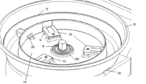
次に、本発明の陶芸用ろくろの一実施形態を図面にもとづいて説明する。図1は、本発明の一実施形態における陶芸用ろくろの外観斜視図であり、図2は、同陶芸用ろくろの分解図である。また、図3は、図1のA−A断面を示す図である。 Next, an embodiment of the potter's wheel according to the present invention will be described with reference to the drawings. FIG. 1 is an external perspective view of a pottery wheel according to an embodiment of the present invention, and FIG. 2 is an exploded view of the pottery wheel. FIG. 3 is a cross-sectional view taken along the line AA in FIG.
図1〜図3に示すように、陶芸用ろくろ1は、ろくろ本体2と、固定テーブル3と、回転テーブル4と、どべ受け5など、を備えている。
As shown in FIGS. 1 to 3, the ceramic potter's
ろくろ本体2は、使用時にはテーブルや床面(図示略)などに載置され、陶芸用ろくろ1のベースとなる部材である。ろくろ本体2の内部には、回転軸6の駆動源となる駆動モータ(図示略)の他、制御装置(図示略)などが備えられており、また、ろくろ本体2の側面には、陶芸用ろくろ1のオンオフスイッチである電源スイッチ7と、固定テーブル3の回転速度を調整するための回転操作スイッチ8などを備えられている。なお、ろくろ本体2には、別途固定テーブル3の回転方向(正逆回転)を操作するための操作スイッチ(図示略)も設けられている。また、後述するように、ろくろ本体2の上面には、どべ受け5に設けられた突起部9と係止するストッパー10が設けられ、また、回転軸6の周辺を上部に突起させた泥水浸入防止突起部100が設けられている。
The potter's
固定テーブル3は、円板状形状で、ろくろ本体1の上部に取り付けられる。固定テーブル3は、回転軸6により軸着されている。これにより、駆動モータの駆動力により、固定テーブル3を回転させることができる。また、後述するように、固定テーブル3の上面には、回転テーブル4の位置を規制する位置規制突起部12が設けられている。なお、回転軸6は、図3に示すように、軸受11により支持されている。
The fixed table 3 has a disk shape and is attached to the upper portion of the potter's
回転テーブル4は、円板状形状で、固定テーブル3の上部に取り付けられる。回転テーブル4の下面には、固定テーブル3の位置規制突起部12と勘合する位置規制凹部13が設けられている。この位置規制凹部13に位置規制突起部12が勘合されることにより、固定テーブル3に対する回転テーブル4の位置を固定して、回転テーブル4を設置することができる。なお、回転テーブル4は、合成樹脂などでできている。
The rotary table 4 has a disk shape and is attached to the upper part of the fixed table 3. On the lower surface of the rotary table 4, a position restricting recess 13 that engages with the
このように、ろくろ本体2の内部に設けられた駆動モータの駆動力により、回転テーブル4を固定テーブル3と一体となって回転させることができる。
Thus, the rotary table 4 can be rotated integrally with the fixed table 3 by the driving force of the drive motor provided inside the potter's
どべ受け5は、回転テーブル4の上面から飛び散るまたは落下する泥水などを受けるもので、中央部に開口部14を有し、回転テーブル4の下方および側方を覆うように配置されている。どべ受け5は、底面部15と、底面部15の外周部から上方に延びる内面側壁部16と外面側壁部17とを有しており、この底面部15と内面側壁部16と外面側壁部17から回転テーブル4の上面から飛び散るまたは落下する泥水などを受ける凹部18が形成されている。また、どべ受け5の凹部18の内面には、泥水などが凹部18から溢れ出す目安を示すオーバーフロー限界ライン19が設けられ、さらに、どべ受け5の外面には、凹部18から溢れ出した泥水などを陶芸用ろくろ1の外部に排出するための排水溝20が形成されている。また、上述したように、どべ受け5の開口部14近傍には突起部9が設けられ、この突起部9がろくろ本体2に設けられたストッパー10に係止することにより、どべ受け5がろくろ本体2に固定して取り付けられる。ここで、どべ受け5の開口部14の径は、固定テーブル3の外径より大きく、回転テーブル4の外径より小さく形成されている。
The
次に、本発明の一実施形態における陶芸用ろくろ1を組立方法について説明する。
Next, a method for assembling the potter's
まず、テーブルなどに載置されたろくろ本体2の上部から固定テーブル3が取り付けられる(図2、図3参照)。これにより、固定テーブル3は、回転軸6に固定された状態で取り付けられる。
First, the fixed table 3 is attached from the top of the potter's
次に、どべ受け5をろくろ本体2に取り付けるが、どべ受け5の開口部14の径は、固定テーブル3の外径よりも大きく形成されているので、どべ受け5の開口部14に固定テーブル3を通して、取り付けることができる。この取り付けに際しては、図4に示すように、どべ受け5を回転させて、どべ受け5に設けられた突起部9をろくろ本体2に設けられたストッパー10に係止させる。これにより、どべ受け5が、ろくろ本体2に固定された状態で取り付けられる(図5参照)。
Next, the
ここで、図4は、本発明の一実施形態におけるどべ受けの取付方法を示す図であり、図5は、本発明の一実施形態におけるどべ受けの突起部とろくろ本体のストッパーが噛合った状態を示す図である。 Here, FIG. 4 is a view showing a method of attaching the dovetail according to the embodiment of the present invention, and FIG. 5 is a diagram showing that the protrusion of the dovetail and the stopper of the potter's wheel body according to the embodiment of the present invention are engaged. FIG.
次に、固定テーブル3およびどべ受け5をろくろ本体2に取り付けた状態で、回転テーブル4を取り付ける。この取り付けに際しては、固定テーブル3の上面に設けられた位置規制突起部12を回転テーブル4の下面に設けられた位置規制凹部13に勘合させる。これにより、回転テーブル4が、固定テーブル3に固定された状態で取り付けることができる。
Next, the rotary table 4 is attached in a state in which the fixed table 3 and the
次に、本発明の一実施形態におけるどべ受け5の取外方法について説明する。
Next, the removal method of the
まず、回転テーブル4を取り外す。回転テーブル4は、固定テーブル3の位置規制突起部12が回転テーブル4の位置規制凹部13に勘合されて取り付けられているので、回転テーブル4を上部に持ち上げることにより、取り外すことができる。
First, the
次に、どべ受け5を取り外す。どべ受け5は、ろくろ本体2のストッパー10にどべ受け5の突起部9が係止されて取り付けられているので、どべ受け5を回転(図4と逆方向)させて上部に持ち上げることにより、取り外すことができる。
Next, the
このように、どべ受け5の開口部14の径を、固定テーブル3の外径より大きくし、回転テーブル4の外径より小さくしているので、どべ受け5の取り外しの際に、固定テーブル3を取り外す必要がなく、どべ受け5を回転させ上部に引き上げることにより、陶芸用ろくろ1からどべ受け5を容易に取り外すことができる。さらに、どべ受け5を上部に引き上げることにより、陶芸用ろくろ1からどべ受け5を取り外すことができるので、凹部18に溜まった泥水などをこぼすといったおそれもない。
As described above, the diameter of the
以上説明したように、どべ受け5の開口部14近傍に設けられた突起部9がろくろ本体2に設けられたストッパー10に係止されることにより、どべ受け5がろくろ本体2に容易に取り付けることができ、どべ受け5をろくろ本体2に固定することができる。また、逆に、突起部9がストッパー10に係止していることを解除することにより、どべ受け5をろくろ本体2から容易に取り外すことができる。
As described above, the
なお、本実施形態では、一体的に形成されたどべ受け5を用いて説明したが、周方向に分割可能などべ受けを使用してもよい。この場合でも、どべ受けを分割せずに使用すれば、一体的に形成されたどべ受け5と同様の作用効果を奏することができる。
In this embodiment, the description has been made using the integrally formed
次に、本発明の一実施形態における陶芸用ろくろ1を使用方法について説明する。まず、電源スイッチ7をオンにして、回転操作スイッチ8を操作することにより、駆動モータが作動し、固定テーブル3および回転テーブル4が回転駆動する。これにより、回転テーブル4上の粘土、水等を用いて陶芸作業を行うことができる。また、この陶芸用ろくろ1では、回転テーブル4から外周側に飛び散る若しくは落下する泥水等は、どべ受け5によって受けられ、どべ受け5の凹部18に溜まっていく。そして、使用者は、どべ受け5の凹部18の泥水などがオーバーフロー限界ライン19まで溜まっているか確認し、オーバーフロー限界ライン19まで溜まっている場合は、どべ受け5を取り外して凹部18内の泥水などを捨て、どべ受け5を洗浄することができる。
Next, a method for using the potter's
このように、どべ受け5の凹部18の内面に、泥水などが凹部18から溢れ出す目安を示すオーバーフロー限界ライン19が設けられているので、陶芸用ろくろ1の使用者は、泥水などがオーバーフロー限界ライン19まで溜まっているかを確認しながら作業することができ、凹部18に溜まった泥水などがこぼれるのを未然に防止することができる。
In this way, since the
そして、どべ受け5の凹部18内の泥水などが、オーバーフロー限界ライン19を超えて溜まっていくと、泥水などが内面側壁部16を超えて、どべ受け5の開口部14内に溢れ出す。そして、この溢れ出した泥水などは、どべ受け5に設けられた排水溝20から陶芸用ろくろ1の外部に排出され、別途用意する泥水受け(図示略)などで受けることができる。
When muddy water or the like in the
このように、どべ受け5の外面に、凹部18から溢れ出した泥水などを外部に排出する排水溝20が形成されているので、この排水溝20からどべ受け5の凹部18から溢れ出した泥水などを外部に排出させることができ、使用者が予期せぬ位置から泥水などが外部へ排出することを防止できる。
As described above, the
また、ろくろ本体2の上面は、凹部18から溢れ出した泥水などが回転軸6の軸受け部に浸入しないように、回転軸6の周辺を上部に突起させた泥水浸入防止突起部100が設けられている。これにより、軸受け部やモータなどの駆動部に泥水などが浸入することがなく、駆動部の不具合を防止することができる。
Further, the upper surface of the potter's
以上に開示された実施の形態はあらゆる点において代表的な例を示すものであり、何ら制限的なものではないと考慮されるべきである。本発明の範囲は上記した実施形態のみによらず、特許請求の範囲によって示されるものであり、特許請求の範囲と均等の意味及び範囲内でのすべての変更が含まれることが意図される。 The embodiments disclosed above are representative examples in all respects and should be considered as not restrictive. The scope of the present invention is shown not by the above-described embodiments but by the scope of claims, and is intended to include all modifications within the meaning and scope equivalent to the scope of claims.
以下、本発明の一実施形態における陶芸用ろくろの変形例について説明する。 Hereinafter, modified examples of the potter's wheel according to the embodiment of the present invention will be described.
(1) 本実施形態では、どべ受け5の開口部14近傍に設けられた突起部9がろくろ本体2に設けられたストッパー10に係止されることにより、どべ受け5がろくろ本体2に取り付けられるようにしたが、これに限らず、突起部9がどべ受け5の開口部14近傍に設けられるものでなく、どべ受け5の底面部15の外周面に設けられるようにしてもよい。この場合、ストッパー10もどべ受け5の底面部15の外周面の下部に設けられることになる。
(1) In this embodiment, the
(2) 本実施形態および変形例1では、どべ受け5に突起部9を設け、ろくろ本体2にストッパー10を設けたが、これに限らず、どべ受け5にストッパーを設け、ろくろ本体2に突起部を設けるようにしてもよい。つまり、どべ受け5とろくろ本体2のいずれか一方に係止部を設け、他方に被係止部を設け、係止部が被係止部に係止されることにより、どべ受け5がろくろ本体2に取り付けられ、ろくろ本体2に固定されものであればよい。
(2) In the present embodiment and the first modification, the
(3) 本実施形態では、どべ受け5の外面に、凹部18から溢れ出した泥水などを外部に排出する排水溝20が形成されるものであったが、必ずしも、排水溝20はどべ受け5の外周面上に形成される必要はなく、どべ受け5から開口部14内に溢れ出した泥水などを陶芸用ろくろ1の外部に排水できる排水溝であれば、ろくろ本体2などに形成されるものであってもよい。これによっても、この排水溝により、どべ受け5の凹部18から溢れ出した泥水などを外部に排出させることができ、使用者が予期せぬ位置から泥水などが外部へ排出することを防止できる。
(3) In the present embodiment, the
(4) 本実施形態では、凹部18から溢れ出した泥水などが回転軸6の軸受け部に浸入しないように、ろくろ本体2上面の回転軸6の周辺を上部に突起させた泥水浸入防止突起部100を設けたが、これに限らず、ろくろ本体2上面に泥水浸入防止突起部100を設けるのではなく、凹部18から溢れ出した泥水などが回転軸6の軸受け部に浸入しないように、ろくろ本体2とは別体に泥水浸入防止部材を設け、それをろくろ本体2に取り付けるようにしてもよい。これによっても、モータなどの駆動部に泥水などが浸入することがなく、駆動部の不具合を防止することができる。
(4) In the present embodiment, the muddy water intrusion preventing protrusion is formed by protruding the periphery of the
1 陶芸用ろくろ
2 ろくろ本体
3 固定テーブル
4 回転テーブル
5 どべ受け
6 回転軸
7 電源スイッチ
8 回転操作スイッチ
9 突起部
10 ストッパー
11 軸受
12 位置規制突起部
13 位置規制凹部
14 開口部
15 底面部
16 内面側壁部
17 外面側壁部
18 凹部
19 オーバーフロー限界ライン
20 排水溝
100 泥水浸入防止突起部
DESCRIPTION OF
Claims (4)
回転軸を回転駆動させる駆動源を有するろくろ本体と、
前記回転軸により回転自在に、前記ろくろ本体の上部に取り付けられる固定テーブルと、
該固定テーブルの上部に取り付けられる回転テーブルと、
中央部に開口部を有し、前記回転テーブルの下方および側方を覆うように配置され、該回転テーブルの上面から飛び散るまたは落下する泥水などを受ける凹部を備えたどべ受けと、を有し、
前記どべ受けの開口部の径は、前記固定テーブルの外径より大きく、前記回転テーブルの外径より小さく、
前記どべ受けは、一体的に形成され、
前記どべ受けは、前記どべ受けの開口部近傍に設けられた突起部を前記ろくろ本体に設けられたストッパーに係止することにより、前記ろくろ本体に取り付けられることを特徴とする陶芸用ろくろ。 A pottery wheel with a rotating table,
A potter's wheel body having a drive source for rotating the rotation shaft;
A fixed table attached to the upper portion of the potter's wheel body so as to be rotatable by the rotating shaft;
A turntable attached to the top of the fixed table;
An opening at the center, arranged to cover the lower side and the side of the rotary table, and having a recess with a recess for receiving muddy water that scatters or falls from the upper surface of the rotary table, ,
The diameter of the opening of the etc. receiving base is larger than the outer diameter of the stationary table, rather smaller than the outer diameter of the rotary table,
The basin is integrally formed,
The potter's wheel is attached to the potter's wheel by engaging a protrusion provided in the vicinity of the opening of the potholder with a stopper provided in the potter's wheel. .
Priority Applications (1)
| Application Number | Priority Date | Filing Date | Title |
|---|---|---|---|
| JP2008031221A JP5154967B2 (en) | 2008-02-13 | 2008-02-13 | Pottery wheel |
Applications Claiming Priority (1)
| Application Number | Priority Date | Filing Date | Title |
|---|---|---|---|
| JP2008031221A JP5154967B2 (en) | 2008-02-13 | 2008-02-13 | Pottery wheel |
Publications (2)
| Publication Number | Publication Date |
|---|---|
| JP2009190206A JP2009190206A (en) | 2009-08-27 |
| JP5154967B2 true JP5154967B2 (en) | 2013-02-27 |
Family
ID=41072678
Family Applications (1)
| Application Number | Title | Priority Date | Filing Date |
|---|---|---|---|
| JP2008031221A Active JP5154967B2 (en) | 2008-02-13 | 2008-02-13 | Pottery wheel |
Country Status (1)
| Country | Link |
|---|---|
| JP (1) | JP5154967B2 (en) |
Cited By (2)
| Publication number | Priority date | Publication date | Assignee | Title |
|---|---|---|---|---|
| CN106426510A (en) * | 2016-11-16 | 2017-02-22 | 重庆市鸦屿陶瓷有限公司 | Multistation automatic water feeding ceramic green body throwing device |
| USD1052625S1 (en) * | 2023-09-11 | 2024-11-26 | Shenzhen Chongheng E-commerce Co., Ltd. | Pottery wheel |
Families Citing this family (8)
| Publication number | Priority date | Publication date | Assignee | Title |
|---|---|---|---|---|
| JP5729689B2 (en) * | 2010-03-27 | 2015-06-03 | 日本電産シンポ株式会社 | A potter's wheel pot and a pottery pot equipped with it. |
| CN103331804B (en) * | 2013-07-01 | 2015-06-10 | 车强 | Ceramic cylinder mud production machine |
| CN109421145A (en) * | 2017-08-25 | 2019-03-05 | 陶朴科技(上海)有限公司 | Ceramic throwing machine |
| CN108356956A (en) * | 2018-05-02 | 2018-08-03 | 石文革 | A kind of ceramic withdrawal device |
| CN108858663A (en) * | 2018-07-18 | 2018-11-23 | 白徽强 | A kind of ceramic withdrawal device |
| USD983238S1 (en) * | 2019-07-30 | 2023-04-11 | Vasudev R. | Potter's wheel |
| KR102431053B1 (en) * | 2019-11-29 | 2022-08-09 | 이호영 | Disc Porcelain Molding Machine |
| CN120503294B (en) * | 2025-07-07 | 2026-01-16 | 通化师范学院 | Shaping turntable for clay sculpture artware |
Family Cites Families (3)
| Publication number | Priority date | Publication date | Assignee | Title |
|---|---|---|---|---|
| JPH0241905U (en) * | 1988-09-14 | 1990-03-22 | ||
| JPH0447503U (en) * | 1990-08-28 | 1992-04-22 | ||
| JP2001121519A (en) * | 1999-10-26 | 2001-05-08 | Toshie Osada | Potter's wheel device |
-
2008
- 2008-02-13 JP JP2008031221A patent/JP5154967B2/en active Active
Cited By (3)
| Publication number | Priority date | Publication date | Assignee | Title |
|---|---|---|---|---|
| CN106426510A (en) * | 2016-11-16 | 2017-02-22 | 重庆市鸦屿陶瓷有限公司 | Multistation automatic water feeding ceramic green body throwing device |
| CN106426510B (en) * | 2016-11-16 | 2017-10-13 | 重庆市鸦屿陶瓷有限公司 | A kind of multistation automatic loading water ceramic batch drawing device |
| USD1052625S1 (en) * | 2023-09-11 | 2024-11-26 | Shenzhen Chongheng E-commerce Co., Ltd. | Pottery wheel |
Also Published As
| Publication number | Publication date |
|---|---|
| JP2009190206A (en) | 2009-08-27 |
Similar Documents
| Publication | Publication Date | Title |
|---|---|---|
| JP5154967B2 (en) | Pottery wheel | |
| US20160045072A1 (en) | Salad spinner | |
| JP2018174820A (en) | Pot stand with water reception function | |
| KR101314368B1 (en) | Splash pan of a pottery wheel and pottery wheel provided with the same | |
| JP2011244910A (en) | Electric cooker | |
| JP4811296B2 (en) | Household rice milling machine | |
| JP3916573B2 (en) | Juicer | |
| JP3052694U (en) | Potter's wheel | |
| JP4453381B2 (en) | Water storage device | |
| CN102431599A (en) | Spare tire cover | |
| JP4404587B2 (en) | Potter's wheel pot and pottery pot equipped with it | |
| JP5590291B2 (en) | Drainage device and washing water tank having the same | |
| JP2008272260A (en) | Drink server | |
| KR100923916B1 (en) | Sink bowl with dewatering device | |
| JP6761994B2 (en) | Ice Pale | |
| JP3233132B2 (en) | Juicer | |
| CN106347318B (en) | A kind of automobile-used foot mat and automobile-used foot mat cleaning machine | |
| JP7594189B2 (en) | lid | |
| JP2012135417A (en) | Sewing machine and oil tank of sewing machine | |
| JPH044673Y2 (en) | ||
| JP3916587B2 (en) | Juicer | |
| JP2004337285A (en) | Juicer | |
| JP2588998B2 (en) | Cooking device | |
| JP4440846B2 (en) | Chrysanthemum crack cover for drain | |
| JPH0957118A (en) | Rice washing machine |
Legal Events
| Date | Code | Title | Description |
|---|---|---|---|
| A621 | Written request for application examination |
Free format text: JAPANESE INTERMEDIATE CODE: A621 Effective date: 20110204 |
|
| A977 | Report on retrieval |
Free format text: JAPANESE INTERMEDIATE CODE: A971007 Effective date: 20120517 |
|
| A131 | Notification of reasons for refusal |
Free format text: JAPANESE INTERMEDIATE CODE: A131 Effective date: 20120521 |
|
| A521 | Request for written amendment filed |
Free format text: JAPANESE INTERMEDIATE CODE: A523 Effective date: 20120718 |
|
| TRDD | Decision of grant or rejection written | ||
| A01 | Written decision to grant a patent or to grant a registration (utility model) |
Free format text: JAPANESE INTERMEDIATE CODE: A01 Effective date: 20121113 |
|
| A61 | First payment of annual fees (during grant procedure) |
Free format text: JAPANESE INTERMEDIATE CODE: A61 Effective date: 20121206 |
|
| FPAY | Renewal fee payment (event date is renewal date of database) |
Free format text: PAYMENT UNTIL: 20151214 Year of fee payment: 3 |
|
| R150 | Certificate of patent or registration of utility model |
Ref document number: 5154967 Country of ref document: JP Free format text: JAPANESE INTERMEDIATE CODE: R150 Free format text: JAPANESE INTERMEDIATE CODE: R150 |
|
| R250 | Receipt of annual fees |
Free format text: JAPANESE INTERMEDIATE CODE: R250 |
|
| R250 | Receipt of annual fees |
Free format text: JAPANESE INTERMEDIATE CODE: R250 |
|
| R250 | Receipt of annual fees |
Free format text: JAPANESE INTERMEDIATE CODE: R250 |
|
| R250 | Receipt of annual fees |
Free format text: JAPANESE INTERMEDIATE CODE: R250 |
|
| R250 | Receipt of annual fees |
Free format text: JAPANESE INTERMEDIATE CODE: R250 |
|
| R250 | Receipt of annual fees |
Free format text: JAPANESE INTERMEDIATE CODE: R250 |
|
| R250 | Receipt of annual fees |
Free format text: JAPANESE INTERMEDIATE CODE: R250 |
|
| R250 | Receipt of annual fees |
Free format text: JAPANESE INTERMEDIATE CODE: R250 |
|
| R250 | Receipt of annual fees |
Free format text: JAPANESE INTERMEDIATE CODE: R250 |
|
| R250 | Receipt of annual fees |
Free format text: JAPANESE INTERMEDIATE CODE: R250 |
|
| R250 | Receipt of annual fees |
Free format text: JAPANESE INTERMEDIATE CODE: R250 |