JP5154452B2 - Fluid transfer mechanism - Google Patents
Fluid transfer mechanism Download PDFInfo
- Publication number
- JP5154452B2 JP5154452B2 JP2008554877A JP2008554877A JP5154452B2 JP 5154452 B2 JP5154452 B2 JP 5154452B2 JP 2008554877 A JP2008554877 A JP 2008554877A JP 2008554877 A JP2008554877 A JP 2008554877A JP 5154452 B2 JP5154452 B2 JP 5154452B2
- Authority
- JP
- Japan
- Prior art keywords
- chamber
- fluid
- opening
- barrier layer
- fluid transfer
- Prior art date
- Legal status (The legal status is an assumption and is not a legal conclusion. Google has not performed a legal analysis and makes no representation as to the accuracy of the status listed.)
- Expired - Fee Related
Links
Images


Classifications
-
- B—PERFORMING OPERATIONS; TRANSPORTING
- B01—PHYSICAL OR CHEMICAL PROCESSES OR APPARATUS IN GENERAL
- B01L—CHEMICAL OR PHYSICAL LABORATORY APPARATUS FOR GENERAL USE
- B01L3/00—Containers or dishes for laboratory use, e.g. laboratory glassware; Droppers
- B01L3/50—Containers for the purpose of retaining a material to be analysed, e.g. test tubes
- B01L3/502—Containers for the purpose of retaining a material to be analysed, e.g. test tubes with fluid transport, e.g. in multi-compartment structures
- B01L3/5027—Containers for the purpose of retaining a material to be analysed, e.g. test tubes with fluid transport, e.g. in multi-compartment structures by integrated microfluidic structures, i.e. dimensions of channels and chambers are such that surface tension forces are important, e.g. lab-on-a-chip
- B01L3/502738—Containers for the purpose of retaining a material to be analysed, e.g. test tubes with fluid transport, e.g. in multi-compartment structures by integrated microfluidic structures, i.e. dimensions of channels and chambers are such that surface tension forces are important, e.g. lab-on-a-chip characterised by integrated valves
-
- F—MECHANICAL ENGINEERING; LIGHTING; HEATING; WEAPONS; BLASTING
- F16—ENGINEERING ELEMENTS AND UNITS; GENERAL MEASURES FOR PRODUCING AND MAINTAINING EFFECTIVE FUNCTIONING OF MACHINES OR INSTALLATIONS; THERMAL INSULATION IN GENERAL
- F16K—VALVES; TAPS; COCKS; ACTUATING-FLOATS; DEVICES FOR VENTING OR AERATING
- F16K99/00—Subject matter not provided for in other groups of this subclass
- F16K99/0001—Microvalves
- F16K99/0003—Constructional types of microvalves; Details of the cutting-off member
- F16K99/0017—Capillary or surface tension valves, e.g. using electro-wetting or electro-capillarity effects
-
- F—MECHANICAL ENGINEERING; LIGHTING; HEATING; WEAPONS; BLASTING
- F16—ENGINEERING ELEMENTS AND UNITS; GENERAL MEASURES FOR PRODUCING AND MAINTAINING EFFECTIVE FUNCTIONING OF MACHINES OR INSTALLATIONS; THERMAL INSULATION IN GENERAL
- F16K—VALVES; TAPS; COCKS; ACTUATING-FLOATS; DEVICES FOR VENTING OR AERATING
- F16K99/00—Subject matter not provided for in other groups of this subclass
- F16K99/0001—Microvalves
- F16K99/0003—Constructional types of microvalves; Details of the cutting-off member
- F16K99/0025—Valves using microporous membranes
-
- B—PERFORMING OPERATIONS; TRANSPORTING
- B01—PHYSICAL OR CHEMICAL PROCESSES OR APPARATUS IN GENERAL
- B01L—CHEMICAL OR PHYSICAL LABORATORY APPARATUS FOR GENERAL USE
- B01L2200/00—Solutions for specific problems relating to chemical or physical laboratory apparatus
- B01L2200/14—Process control and prevention of errors
- B01L2200/143—Quality control, feedback systems
-
- B—PERFORMING OPERATIONS; TRANSPORTING
- B01—PHYSICAL OR CHEMICAL PROCESSES OR APPARATUS IN GENERAL
- B01L—CHEMICAL OR PHYSICAL LABORATORY APPARATUS FOR GENERAL USE
- B01L2300/00—Additional constructional details
- B01L2300/06—Auxiliary integrated devices, integrated components
- B01L2300/0627—Sensor or part of a sensor is integrated
- B01L2300/0645—Electrodes
-
- B—PERFORMING OPERATIONS; TRANSPORTING
- B01—PHYSICAL OR CHEMICAL PROCESSES OR APPARATUS IN GENERAL
- B01L—CHEMICAL OR PHYSICAL LABORATORY APPARATUS FOR GENERAL USE
- B01L2300/00—Additional constructional details
- B01L2300/08—Geometry, shape and general structure
- B01L2300/0809—Geometry, shape and general structure rectangular shaped
- B01L2300/0816—Cards, e.g. flat sample carriers usually with flow in two horizontal directions
-
- B—PERFORMING OPERATIONS; TRANSPORTING
- B01—PHYSICAL OR CHEMICAL PROCESSES OR APPARATUS IN GENERAL
- B01L—CHEMICAL OR PHYSICAL LABORATORY APPARATUS FOR GENERAL USE
- B01L2300/00—Additional constructional details
- B01L2300/08—Geometry, shape and general structure
- B01L2300/0809—Geometry, shape and general structure rectangular shaped
- B01L2300/0825—Test strips
-
- B—PERFORMING OPERATIONS; TRANSPORTING
- B01—PHYSICAL OR CHEMICAL PROCESSES OR APPARATUS IN GENERAL
- B01L—CHEMICAL OR PHYSICAL LABORATORY APPARATUS FOR GENERAL USE
- B01L2300/00—Additional constructional details
- B01L2300/08—Geometry, shape and general structure
- B01L2300/0861—Configuration of multiple channels and/or chambers in a single devices
- B01L2300/0874—Three dimensional network
-
- B—PERFORMING OPERATIONS; TRANSPORTING
- B01—PHYSICAL OR CHEMICAL PROCESSES OR APPARATUS IN GENERAL
- B01L—CHEMICAL OR PHYSICAL LABORATORY APPARATUS FOR GENERAL USE
- B01L2300/00—Additional constructional details
- B01L2300/08—Geometry, shape and general structure
- B01L2300/0887—Laminated structure
-
- B—PERFORMING OPERATIONS; TRANSPORTING
- B01—PHYSICAL OR CHEMICAL PROCESSES OR APPARATUS IN GENERAL
- B01L—CHEMICAL OR PHYSICAL LABORATORY APPARATUS FOR GENERAL USE
- B01L2400/00—Moving or stopping fluids
- B01L2400/04—Moving fluids with specific forces or mechanical means
- B01L2400/0403—Moving fluids with specific forces or mechanical means specific forces
- B01L2400/0406—Moving fluids with specific forces or mechanical means specific forces capillary forces
-
- B—PERFORMING OPERATIONS; TRANSPORTING
- B01—PHYSICAL OR CHEMICAL PROCESSES OR APPARATUS IN GENERAL
- B01L—CHEMICAL OR PHYSICAL LABORATORY APPARATUS FOR GENERAL USE
- B01L2400/00—Moving or stopping fluids
- B01L2400/04—Moving fluids with specific forces or mechanical means
- B01L2400/0475—Moving fluids with specific forces or mechanical means specific mechanical means and fluid pressure
- B01L2400/0487—Moving fluids with specific forces or mechanical means specific mechanical means and fluid pressure fluid pressure, pneumatics
-
- B—PERFORMING OPERATIONS; TRANSPORTING
- B01—PHYSICAL OR CHEMICAL PROCESSES OR APPARATUS IN GENERAL
- B01L—CHEMICAL OR PHYSICAL LABORATORY APPARATUS FOR GENERAL USE
- B01L2400/00—Moving or stopping fluids
- B01L2400/06—Valves, specific forms thereof
- B01L2400/0688—Valves, specific forms thereof surface tension valves, capillary stop, capillary break
-
- F—MECHANICAL ENGINEERING; LIGHTING; HEATING; WEAPONS; BLASTING
- F16—ENGINEERING ELEMENTS AND UNITS; GENERAL MEASURES FOR PRODUCING AND MAINTAINING EFFECTIVE FUNCTIONING OF MACHINES OR INSTALLATIONS; THERMAL INSULATION IN GENERAL
- F16K—VALVES; TAPS; COCKS; ACTUATING-FLOATS; DEVICES FOR VENTING OR AERATING
- F16K99/00—Subject matter not provided for in other groups of this subclass
- F16K2099/0073—Fabrication methods specifically adapted for microvalves
- F16K2099/008—Multi-layer fabrications
-
- F—MECHANICAL ENGINEERING; LIGHTING; HEATING; WEAPONS; BLASTING
- F16—ENGINEERING ELEMENTS AND UNITS; GENERAL MEASURES FOR PRODUCING AND MAINTAINING EFFECTIVE FUNCTIONING OF MACHINES OR INSTALLATIONS; THERMAL INSULATION IN GENERAL
- F16K—VALVES; TAPS; COCKS; ACTUATING-FLOATS; DEVICES FOR VENTING OR AERATING
- F16K99/00—Subject matter not provided for in other groups of this subclass
- F16K2099/0082—Microvalves adapted for a particular use
- F16K2099/0086—Medical applications
-
- Y—GENERAL TAGGING OF NEW TECHNOLOGICAL DEVELOPMENTS; GENERAL TAGGING OF CROSS-SECTIONAL TECHNOLOGIES SPANNING OVER SEVERAL SECTIONS OF THE IPC; TECHNICAL SUBJECTS COVERED BY FORMER USPC CROSS-REFERENCE ART COLLECTIONS [XRACs] AND DIGESTS
- Y10—TECHNICAL SUBJECTS COVERED BY FORMER USPC
- Y10T—TECHNICAL SUBJECTS COVERED BY FORMER US CLASSIFICATION
- Y10T436/00—Chemistry: analytical and immunological testing
- Y10T436/25—Chemistry: analytical and immunological testing including sample preparation
- Y10T436/2575—Volumetric liquid transfer
Description
本発明は、一般に流体移送機構に関する。本発明に係る実施例は、医療用流体検査機構に関する。 The present invention generally relates to fluid transfer mechanisms. Embodiments according to the present invention relate to a medical fluid testing mechanism.
一部の検出ストリップの設計においては、流体を、所定の時間の経過後に、第1の室から第2の室、あるいは追加の室に導入できるように、2つ、あるいはそれ以上の室が必要とされる。特に、米国特許出願番号第10/830,841号、および11/284,097号に開示する免疫測定用検出ストリップにおいては、少なくとも2つの室があり、第1の反応室と第2の検出室がある。使用においては、最初に、液体を反応室に導入し、免疫結合反応が進行する所定の時間滞留させた後に、検出室に導入する。この決められた時間での移送は、次のように行われる。検出室は、反応室に開口しており、また反応室から離れた端にある通気孔は、初期状態では閉じている。反応室に液体が満たされると、検出室への開口が液体により閉じられる。検出室に閉じ込められた空気が、液体が検出室に流れ込むのを防止している。検出室に液体を満たすときは、反応室から離れた端にある通気孔を、通常、層に穴を開けて開通し、反応室の液体の一部、または液溜めから引き込まれた試料を、反応室から検出室に移送する。 Some detection strip designs require two or more chambers so that the fluid can be introduced from the first chamber to the second chamber or additional chambers after a predetermined period of time. It is said. In particular, in the detection strip for immunoassay disclosed in US Patent Application Nos. 10 / 830,841 and 11 / 284,097, there are at least two chambers, a first reaction chamber and a second detection chamber. There is. In use, first, a liquid is introduced into the reaction chamber, allowed to stay for a predetermined time during which the immune binding reaction proceeds, and then introduced into the detection chamber. The transfer at the determined time is performed as follows. The detection chamber is open to the reaction chamber, and the vent at the end away from the reaction chamber is closed in the initial state. When the reaction chamber is filled with liquid, the opening to the detection chamber is closed by the liquid. Air trapped in the detection chamber prevents liquid from flowing into the detection chamber. When filling the detection chamber with liquid, the vent at the end away from the reaction chamber is usually opened with a hole in the layer and a portion of the liquid in the reaction chamber or the sample drawn from the reservoir is Transfer from reaction chamber to detection chamber.
しかしながら、上記の方法には、潜在的な欠点がいくつかある。全血を検査する際に、試料の粘度により、検出室への入口を確実に閉じるのが困難である。これは、反応室への流入の際に、異なる量の液体が検出室に流入することになり、反応のばらつきが増えてしまう。また、測定器の長期の使用において、反復使用により針、または刃が鈍る可能性があり、通気孔の貫通方法の信頼性が確保されない。故に、このような問題を解決する流体移送の方法の開発が求められる。 However, the above method has some potential drawbacks. When examining whole blood, it is difficult to reliably close the entrance to the detection chamber due to the viscosity of the sample. This is because when the liquid flows into the reaction chamber, different amounts of liquid flow into the detection chamber, thereby increasing the dispersion of the reaction. Moreover, in the long-term use of a measuring device, a needle | hook or a blade may become blunt by repeated use, and the reliability of the penetration method of a vent hole is not ensured. Therefore, development of a fluid transfer method that solves such problems is required.
本発明の実施形態は、受動的な移動力を使って少量の液体を室間で移送する、信頼性が高く、堅牢な方法を提供することを目的とする。この方法では、多孔性の壁を、液体を移送する室の間に設けている。多孔性の壁は微細孔を有し、この微細孔の大きさは、移送する液体を満たすには十分大きく、開始の操作を行なうまでは、第2の室への液界面の表面張力により、液体が微細孔から第2の室に漏れない程度に小さい。 Embodiments of the present invention aim to provide a reliable and robust method of transferring small amounts of liquid between chambers using passive movement forces. In this method, a porous wall is provided between the chambers for transferring the liquid. The porous wall has micropores, the size of the micropores being large enough to fill the liquid to be transferred and until the start operation, due to the surface tension of the liquid interface to the second chamber, The liquid is small enough not to leak from the fine holes into the second chamber.
液体は、多孔性の壁を濡らして、少なくとも部分的に微細孔を満たすように第1の室に導入される。しかしながら、液体は、この時点では、表面張力により、多孔性の壁の反対側の孔から出て、第2の室には入らない。液体を第2の室に移送する際は、表面張力を克服して、あるいは打ち破って、液体を微細孔から第2の室に流出させる開始の操作を行なう。 The liquid is introduced into the first chamber so as to wet the porous wall and at least partially fill the micropores. However, at this point, the liquid will exit the hole on the opposite side of the porous wall due to surface tension and will not enter the second chamber. When the liquid is transferred to the second chamber, the operation of starting the flow of the liquid from the fine hole to the second chamber is performed by overcoming or breaking the surface tension.
開始の操作とは、液体を壁中の微細孔内に保持している表面張力を克服して、液体の第2の室への流入を許容することである。開始の操作は、第1の室の液体に圧力パルスを加える、第2の室を減圧状態にする、検出ストリップを振動する、第2の室に対向する多孔性の壁の表面に触れる、または表面張力を克服する、もしくは打ち破るその他の方法で行なう。 The starting operation is to overcome the surface tension holding the liquid in the micropores in the wall and allow the liquid to flow into the second chamber. The starting operation applies a pressure pulse to the liquid in the first chamber, depressurizes the second chamber, vibrates the detection strip, touches the surface of the porous wall opposite the second chamber, or Any other method that overcomes or breaks the surface tension.
所望の時間に所望の第2の室に開始の操作を行なうことにより、複数の第2の室を1つの第1の室からの液体で、同時に、あるいは異なる時に満たすことができる。また、第3の室に接続する第2の室の微細孔の壁を少なくとも部分的に有し、移送が要求されたときに第3の室に開始の操作を施すことにより、第3の室は第2の室からの液体で満たされ得る。それ以降に続く、並列、または直列に設けられた室においても、同様に繰り返すことができる。 By performing a start operation on a desired second chamber at a desired time, a plurality of second chambers can be filled with liquid from one first chamber simultaneously or at different times. The third chamber has at least a part of the wall of the fine hole of the second chamber connected to the third chamber, and when the transfer is requested, the third chamber is started. Can be filled with liquid from the second chamber. The same can be repeated in the subsequent chambers provided in parallel or in series.
本発明の特定の実施形態は、第1の室から第2の室に液体を移送する流体移送装置を提供するものである。本装置は、第1の室と、第2の室と、第1の室と第2の室との間の障壁と、を有し、障壁は第1の室と第2の室とを流体的に接続する少なくとも1つの開口を有し、少なくとも1つの開口は第1の室の液体を保持する保持力をもつ大きさである。液体に保持力を十分に克服する大きさの開始の操作が行われると、液体が第1の室から第2の室に移送される。 Certain embodiments of the present invention provide a fluid transfer device for transferring liquid from a first chamber to a second chamber. The apparatus includes a first chamber, a second chamber, and a barrier between the first chamber and the second chamber, the barrier fluidizing the first chamber and the second chamber. At least one opening connected to the first chamber, the at least one opening being sized to hold the liquid in the first chamber. When a start operation is performed that is large enough to overcome the holding power of the liquid, the liquid is transferred from the first chamber to the second chamber.
本発明の別の実施形態は、第1の室から第2の室に液体を移送する方法を提供するものである。この方法は、第1の室を設け、第2の室を設け、第1の室と第2の室との間に第1の室と第2の室とを流体的に接続する少なくとも1つの開口を有し、少なくとも1つの開口は第1の室の液体を保持する保持力を持つ大きさの障壁を設け、液体を第1の室から第2の室に移送する方法である。液体の移送は、液体に、保持力を十分に克服する大きさの開始の操作が行われた際に行われる。 Another embodiment of the present invention provides a method for transferring liquid from a first chamber to a second chamber. The method includes providing a first chamber, providing a second chamber, and fluidly connecting the first chamber and the second chamber between the first chamber and the second chamber. There is an opening, and at least one opening is provided with a barrier having a holding capacity for holding the liquid in the first chamber, and the liquid is transferred from the first chamber to the second chamber. The liquid is transferred when the liquid is subjected to a starting operation of a size that sufficiently overcomes the holding force.
本発明における前述、およびその他の特徴、ならびに有利性は、以下の添付図面を用いて、本発明に係る実施形態の詳細な説明により明らかとなる。添付図面においては、一般に、同一の、および機能的に同等の、または構造的に同等の要素は同じ参照番号で示す。 The foregoing and other features and advantages of the present invention will become apparent from the following detailed description of embodiments of the present invention, with reference to the accompanying drawings. In the drawings, generally, identical, functionally equivalent, or structurally equivalent elements are designated with the same reference numerals.
本発明について、2つの室を有し、特定の開始の操作を行なう実施形態を参照して説明する。本実施形態は、免疫結合の反応結果を、電気化学的に検出する、使い捨て型の免疫測定用検出ストリップに関する。ここで、以下の説明に使われる「上、下」とは説明の利便性のためで、本装置の使用時の好ましい向きなどを特定するものではない。また、本装置はあらゆる向きにおいて使用可能である。 The present invention will be described with reference to an embodiment having two chambers and performing a specific starting operation. The present embodiment relates to a disposable immunoassay detection strip for electrochemically detecting a reaction result of immunological binding. Here, the terms “upper and lower” used in the following description are for convenience of description, and do not specify a preferred direction when the apparatus is used. Moreover, this apparatus can be used in all directions.
検出ストリップは、充填室、反応室、および検出室の3つの室からなる。充填室は、試料を受け入れ、試料液溜めとして機能する。反応室は、試薬を含有し、試料中の検体の有無または濃度により程度の異なるプローブが反応室内で選択的に固定化される。検出室は、電極を有し、試薬を含有し、反応室から液体と共に移送されたプローブの量を検出し、よって元の試料に含まれていた抗体の量を検出、あるいは数量化することができる。この検出ストリップの例を、図1から図3に示す。検出ストリップ100は、複数の層からなり、接着剤を使って積層してある。検出ストリップは、充填室1、反応室2、および検出室3、の3つの室からなる。層10および層70は、充填室1の両面を閉じ、細管部を形成する封止層である。層20は、検出室3の電極として機能する導電性の上面を有する層である。層30および層50は、上面および下面に接着面を有するスペーサ層である。層30および層50は、積層部を保持し、それぞれ検出室、および反応室の高さを規定している。図2および図3に示す層30の切欠き部は、検出室3の領域と、検出室電極部の領域を規定している。図2および図3に示す層50の切欠き部は、反応室2の領域を規定している。層40は、反応室2と検出室3とを接続する微細孔となる微細孔を有する層である。層40は、下面に、検出室3の第2の電極として機能する導電性の被膜を有している。層60は、反応室2と充填室1を閉じている。任意の選択肢として、層60は、下面に、反応室2での液体の充満を検出する電極となる導電性の被膜を有してもよい。この場合、液体が反応室2と層40の微細孔を満たし、層40の下面の電極と層60の下面の電極とが電気的に接続される。この電気的接続を検出し、測定器に検査手順の開始を伝えることができる。層10および層70は、それぞれ層20および層60に任意の適切な方法で固定される。好ましい方法としては、接着剤を使用する。実施形態の1つでは、層20の下面、および層60の上面に接着剤を塗布し、層10および層70を接着剤層に積層する。または、接着剤を層10および層70に塗布し、それらを層20および層60に積層してもよい。
The detection strip consists of three chambers: a filling chamber, a reaction chamber, and a detection chamber. The filling chamber receives the sample and functions as a sample reservoir. The reaction chamber contains a reagent, and probes having different degrees depending on the presence / absence or concentration of the analyte in the sample are selectively immobilized in the reaction chamber. The detection chamber has electrodes, contains reagents, detects the amount of probe transferred with the liquid from the reaction chamber, and thus can detect or quantify the amount of antibody contained in the original sample. it can. Examples of this detection strip are shown in FIGS. The
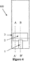
図4から図6は、実施形態の別の例を示し、層50の切欠きにより、全体が切欠き部の壁で囲まれた反応室2を形成している。この実施形態には、反応室2からの液体が、2つの室を接続する多孔性の壁を通過するのではなく、反応室2の開口端から検出室3の開口端に回り込んで、検出室3を濡らしてしまうことを抑制できる利点がある。この実施形態では、反応室2が液体で満たされるのに従い、多孔性の壁の微細孔が全て満たされるか、または反応室2が満たされるまで、中の空気は多孔性の壁の孔を通して排気される。ここでは、正しい動作を行なうために、反応室2を必ずしも完全に満たす必要はなく、反応室2の試薬と接触し、検出室3を満たすのに十分な量の液体があればよい。
FIG. 4 to FIG. 6 show another example of the embodiment, and the
また、図4から図6に示す実施例では、層10と層70を必要とせず、代わりに層20と層60を延在させて充填室1の端壁を形成している。この実施形態では、任意の選択肢として、層20の上面の導電層を充填室1にまで延在させることができる。その際は、液体が反応室2と層40の微細孔を満たすと、充填室1における層20の導電層と層40の下面の導電層とが、液体を介して電気的に接続される。これは、層20と層40における導電層間の抵抗値の低下、または電圧、電流もしくは容量の変化として電気的に検出することができる。これは、液体が検出室3に満たされたという測定器への信号として使用でき、自動的に所定の検査手順を開始することができる。ここで、この方法の利点は、充填室1内の液体が十分な量で、反応室2の開口部に接し、層40の微細孔を満たし始めるまでは、この信号が検知されないということである。ここに、参照によって本願に援用される米国特許第6,571,651号に開示された方法と同じように、充填室1の細管寸法は、反応室2のそれより大きく、充填室1を空けると反応室2を満たすことができるようになっている。そこで、充填室1の大きさが、反応室2と少なくとも同じ、好ましくは僅かに大きい容量であれば、液体が装置に導入されたことを示す信号は、装置が意図した機能を行なうのに十分な量の液体が導入されるまでは検知されない。さらなる利点は、もし最初に十分な量の液体が充填室1に導入されなかった場合、装置の意図した動作に影響を与えずに、十分な量までの液体をさらに追加できることである。反応室2と検出室3との間で液の移送が開始されると、検出室3領域の層20の導電層が濡れることにより、層20と層40における導電性表面間での第2の電気的条件の変化が起こる。この変化を、測定器に、流体の移送が滞りなく行われたという確認のために使用できる。ここで、一般に、充填室1に露出した層20の導電層の領域からの電流信号は、検出室3に露出した導電層の領域で発生する電流信号に比べて小さく、検出室3からの信号の著しい妨害とはならない。これは一般に、天然の試料中には、検出室3の電極間に通常印加される電圧で電流を発生する電気活性種は、低濃度、あるいはごく僅かの量しか存在しないためである。また、充填室1に露出した導電層と層40の導電層との間の比較的長い液経路により、電気抵抗が比較的高くなり、発生する電流信号を抑制することになる。
4 to 6, the
本実施形態の有利性は、検査を行なうのに必要な検出ストリップからの全ての電気信号の検出は、一方を層20の導電層に、他方を層40の導電層に接続する2つの電気的接続のみを必要とすることである。適切な接続端子については、参照によって本願に援用される、米国特許第6,379,513号、ならびに6,946,067号、および米国特許出願第11/284,136号に開示されている。
The advantage of this embodiment is that the detection of all electrical signals from the detection strip necessary to perform the test is performed by two electrical connections, one connected to the conductive layer of
図7に、本装置の別の電気的接続方法を示す。接続装置200を本発明に参照して示しているが、本発明の特徴は、必要に応じ、近接して対向する表面への接続が必要なあらゆる機器に適用され得る。図7において、他の図と共通の番号が付けられた要素は、同じ要素を表している。本特徴の実施形態では、図7は、検出ストリップの充填室1が開口する端とは反対側の端部を示している。この実施形態によれば、層20は、スペーサ層30および層40より伸びて延在している。層20には上面に導電層70があり、層40には下面に導電層90がある。層70および層90のそれぞれに、電気的に接続を行なう必要がある。層40は、スペーサ層30より伸びて延在している。層30から伸びた追加層110が、層20と層40との間に導入されている。層110と導電層80および存在するかもしれない接着剤を加えた厚みは、層30の厚みと同一、またはそれより僅かに大きいことが好ましい。層110は、少なくとも層80の上面が導電性であるが、厚み全体の部分が導電性ではなく、層80と層90とは電気的に接続されるが、層90と層70との間は層110を介して接続されてはいない。層110およびその上の層80は、層40の端から伸びて層80と層90とが電気的に接続されており、層80の層40より延在する領域を介して、層90への電気的接続が行なえる。層110の下面と層70の間に接着剤を介在させ、層110を固定するのが好ましい。任意の選択肢として、層90と層80の間の少なくとも両者が重なる部分に、良好な電気的接続を確保するために導電性接着剤を使ってもよい。または、検出ストリップを外部電気回路に接続するピン、あるいは類似の装置を含む接続ポートを構成し、検出ストリップをポートに挿入した際に、ポートの面が層40の上面を圧し層90が層80を圧して接続するようにしてもよい。
FIG. 7 shows another electrical connection method of the present apparatus. Although the
図8および図9は、3つの活性室を有する装置を使った本発明の実施形態を示す。図8は、3つの活性室と1つの充填室を有する装置の上面図である。図9は、この実施形態の分解図で、種々の層を示す。検出ストリップ700は、充填室800、第1反応室510、移送反応室310、および第2反応室520からなる。層400の穿孔部410は、第1反応室510と移送反応室310とを接続する。層400の穿孔部420は、移送反応室310と第2反応室520とを接続する。使用においては、充填室800の端にある第1反応室510の開口部にまで満たすように、試料を充填室800に加える。充填処理中に排出する空気は、穿孔部410および420を介し、第2反応室の開放端から抜け出る。第1反応室510には、1つあるいはそれ以上の試薬および試薬層を乾燥させておき、例えば試料の前処理などを行なうことができる。第1反応室510での所望の時間の経過後、移送反応室310への流体の移送を、層200が穿孔部410の層400の下面に接するまで、層200を下から押すなどの開示された手段で開始する。これが開始されると、穿孔部420が試液により塞がれ、穿孔部420から空気が抜けられなくなるまで、処理済の試料が第1反応室510から移送反応室310に流れる。任意の選択肢として、移送反応室310には、以下に述べる結合反応など、試料と第2の反応をさせる必要がある場合には、第2の組み合わせの試薬を乾燥させておいてもよい。ここで、全ての室で反応を起こさせることは、本実施例の有利な点ではあるが、必ずしも必要はわけではない。例えば、第1反応室510を、図1から図7の実施例の反応室に対応させ、第2反応室520を、検出室に対応させてもよい。このとき、移送反応室310は、穿孔部420と共に、第1反応室510と第2反応室520とを横方向に分離する単なる移送室として機能する。これは、いくつかの適用においては、第1反応室510内の液からの気体が充満したとき、第2反応室520へ拡散し、試薬が早まって濡れてしまうことを最小に抑えるという利点となる。
8 and 9 show an embodiment of the present invention using a device having three active chambers. FIG. 8 is a top view of an apparatus having three active chambers and one filling chamber. FIG. 9 is an exploded view of this embodiment showing the various layers. The
試料液を移送反応室310に所望の時間滞在させた後、さらに試料を移送反応室310から、穿孔部420を介して、第2反応室520に移送することができる。この移送は、例えば、層600の下面が穿孔部420の少なくともいくつかに接触するように、穿孔部420上部の層600の上面を押すことによって開始させられる。また、試薬を第2反応室520に乾燥させておくことができ、試料内の構成物のさらなる処理、または反応を行なうことができる。例えば、移送反応室310、および第1反応室510で行われた反応の結果を、第2反応室520で検出し、光学的、電気化学的、またはその他の適切な方法で使用可能な信号として変換することができる。
After allowing the sample liquid to stay in the
図9は、本実施形態の種々の室がどのように形成されているかをより詳細に示す。層200および層600は、それぞれ下層および上層の閉塞層で、検出ストリップの細管部の両面を閉じ、穿孔層と接触させて流体移送を開始させるときの層および1つまたはそれ以上の他の層を配置する支持体として機能する。他の層の例としては、電極や電気接続路を形成する導電材の層、種々の室で試料を処理するために必要とされる乾燥試薬層などがある。
FIG. 9 shows in more detail how the various chambers of this embodiment are formed.
層500は、上部スペーサ層である。層500の一部は、切欠き、またはその他の方法で形成され、第1反応室510、および第2反応室520の領域を規定している。層500は、接着剤被膜を両面に施した基板で形成できるが、第1反応室510、および第2反応室520に対応する部分に接着剤を付けずに形成、または配置した接着剤の一層で形成してもよい。接着剤被膜の基板を使用するときは、第1反応室510、および第2反応室520に対応する領域を、パンチング、あるいはその他の方法で、除去する。
層400は、第1反応室510と移送反応室310、および移送反応室310と第2反応室520の障壁として機能し、必要に応じてそれらの間における流体の移送をするのに必要な穿孔部を有する。穿孔部の形成については、本願の他の部分に記載されている。層300は、第2スペーサ層で、移送反応室310の領域を規定する開口部を有する。この層は、上述の層500の方法で形成できる。充填室800は、先ず、領域310、領域510、領域520、穿孔部410、および穿孔部420をそれぞれの層にあらかじめ形成した層300、層400、および層500を積層、またはその他の方法で接合し、その後、三層をパンチングして充填室800の切欠きを形成する。または、層300、層400、および層500の充填室800に対応する領域をそれぞれ別に形成し、各層の切欠き部を揃えて充填室800の側壁を形成するように積層してもよい。充填室800の終端面は、層300、層400、および層500の三層の上面、および下面に、層200、および層600を積層して形成される。
The
図1から図6で示す実施例において、ドライ免疫測定用検出ストリップとして機能させるには、製造段階で、試薬を反応室2、および検出室3内に乾燥させることができる。反応室2の試薬は、結合剤(以降、複合体とする)とリンクするプローブと、結合剤が結合する結合標的からなる。ここで結合標的を持つ種、あるいは結合標的そのものは検出室3への進入を抑制される。例えば、複合体は、検出する検体の抗体とリンクするピロロキノリンキノン依存性グルコースデヒドロゲナーゼ(GDHpqq)などの酵素からなる。標的結合部位は、磁気ビーズ(磁石の小粒)とつながった検出する検体となる。磁気ビーズは、磁石により、反応室2内に収容され、検出室3への進入が抑制される。または、ビーズは磁石である必要はなく、層40の微細孔に納まらず、検出室3への進入が抑制される程度の大きさのものとしてもよい。試料に検体がある場合は、自由な検体が複合体の結合部位と結合し、複合体が固定された標的部位と結合するのを阻止する。このため、複合体は溶液中で自由なままとなり、検出室3へ移送できる。本実施形態では、複合体と標的結合部位は、試料が試薬と接触する前に混合されないようにするのが望ましい。このためには、複合体を層60の下面に乾燥させ、標的結合部位を持つ種を層40の上面に乾燥させることができる。標的結合部位が磁気ビーズにある場合は、層60の上面に隣接して設置した永久磁石、または電磁石によって、反応室2が試料によって満たされ、もともと乾燥していた層から溶け出した磁気ビーズが引き寄せられ、複合体と混合される。また、磁石は磁気ビーズが検出室3に進入するのを抑制する。
In the embodiment shown in FIGS. 1 to 6, the reagent can be dried in the
検出ストリップの製造段階で、検出室3にも試薬を乾燥させておくことができる。この試薬は、プローブの存在を、検出室3の電極間を流れる電流に変換するために必要なものである。本発明の実施形態では、プローブは酵素であり、基質と酵素に電気化学的に活性な媒介物を組み込んでいる。または、酵素の基質は反応室2に組み込んでもよい。これは、基質が活性化するのにある程度の時間が掛かる場合に有利である。プローブがグルコースデヒドロゲナーゼ(GDH)の場合は、グルコースが適切な基質となるが、GDHpqqは、β−D−グルコースでのみ活性状態となる。乾燥した状態のD−グルコースは、大部分はα−D−グルコースであるが、溶解すると変旋光が進行し、β−D−グルコースになる。従って、グルコースを反応室2内の試料中で溶解させ、結合反応が行われている間に、変旋光を行なわせるのが有利である。
The reagent can also be dried in the
プローブを含んだ液体が検出室に入ると、乾燥した薬品を溶解し、薬品とプローブとが反応を開始する。プローブがGDHpqqの場合は、グルコースが適切な基質で、フェリシアニドが適切な媒介物である。GDHpqqの場合、グルコースとフェリシアニドとが混合され、GDHpqqがグルコースを酸化処理して減少し、その後、GDHpqqがフェリシアニドによって再酸化処理されてフェロシアニドを形成する。フェロシアニドは、その後、検出室の陽極で酸化されて測定可能な電流を発生する。この電流はフェロシアニドの発生率に関係し、ひいては、検出室のGDHpqqの濃度に関係し、さらには、元の試料中の検体の濃度に関係する。 When the liquid containing the probe enters the detection chamber, the dried chemical is dissolved, and the chemical and the probe start to react. When the probe is GDHpqq, glucose is a suitable substrate and ferricyanide is a suitable mediator. In the case of GDHpqq, glucose and ferricyanide are mixed, GDHpqq is oxidized to reduce glucose, and then GDHpqq is reoxidized by ferricyanide to form ferrocyanide. The ferrocyanide is then oxidized at the anode of the detection chamber to generate a measurable current. This current is related to the ferrocyanide generation rate, and hence the concentration of GDHpqq in the detection chamber, and further to the concentration of the analyte in the original sample.
最適には、検出室に乾燥させる化学物質は、層20の上面に乾燥させるのがよい。これにより、層40の微細孔を満たした液体が、乾燥した試薬に早まって接触するのを防止できる。さらに、層20の化学物質が反応した試料で溶解されて液体を満たした層40の微細孔に接触する(以下に記載のように)と、検出室への液体の移送を促進する。
Optimally, the chemical to be dried in the detection chamber should be dried on the top surface of the
検出室でGDHpqqを検出するには、反応室で結合反応が所望の時点まで進行する所定の時間の経過後、反応室の液体を検出室に移送しなければならない。液体が反応室を満たしたとき、この時点で、層40の微細孔の親水性により液体は微細孔も満たす。しかしながら、液体が層40の検出室に面した微細孔から流れ出るには、表面張力に対抗して、空気と液体の界面の面積を増やさなければならない。従って、液体は微細孔の底部まで満たされ、そこで止まる。本実施形態では、表面張力を打ち破るため、検出室部分の層20を下から押している。これにより、層20が湾曲し、その上面が層40の下面に接触する。接触部分で、液体が直接層20の上面を濡らし、空気と液体との界面積を増やすことなく、層40の微細孔から流れ出るようになる。しかしながら、押上げ機構が戻され、層20の上面が層40の下面から離れると、表面が離れるにつれて層20を濡らした溶解液も表面から離れ、液体の体積に対する空気と液体の界面の比を最小にしようとして、さらに液体を層40の微細孔から引き寄せることになる。こうして、液体が微細孔を通して検出室が完全に満たされるまで引き寄せられる。ここで、反応室と検出室は、それぞれに液体が正しく満たされるには、液を満たす際に空気を排出できるように、大気中に開口するようにする。図1から図3に示す実施形態では、反応室、および検出室が検出ストリップ100の側面で開放され、排出できるようにしている。図4から図6に示す実施形態では、検出室は検出ストリップの側面の開口から排出され、反応室は層40の微細孔を介して検出室の側面の開口から排出される。
In order to detect GDHpqq in the detection chamber, the liquid in the reaction chamber must be transferred to the detection chamber after a predetermined time has elapsed in which the binding reaction proceeds to a desired time in the reaction chamber. When the liquid fills the reaction chamber, at this point, the liquid also fills the micropores due to the hydrophilic nature of the micropores in the
また、本実施形態が最適に機能するよう、検出室に液体を満たす際は、細管の寸法が同様な室が空になって2つの室の力が対抗し、液の流れが遅くなったり、完全に満たされなくなったりしないようにするのが望ましい。図に示す検出ストリップ100では、充填室の細管の寸法は、反応室、検出室より大きい。このため、検出室が満たされると、充填室に余分の液体が付着していなければ、充填室は空になる。充填室は細管寸法が検出室より大きいので、検出室への充填の妨げが少ない。または、充填室が検出室と同じ細管寸法の場合は、液体の移送に作用するよう、検出室の親水性を充填室のそれより高くしてもよい。一般には、(γd,SL−γd,SA)ΔAd+(γf,SA−γf,SL)ΔAfの値を考慮すべきである。ここで、γは表面張力、ΔAは室の濡れ面積の変化、下付き文字のdは検出室、fは充填室、SLは固液界面、SAは固気界面である。
In addition, when the liquid is filled in the detection chamber so that the present embodiment functions optimally, the chamber with the same size of the thin tube is emptied, the forces of the two chambers counteract, and the flow of the liquid becomes slow, It is desirable not to be completely satisfied. In the
本発明は、従来技術に比べて多くの特徴がある。液体移送を開始するのに、穴あけ機構ではなく、押出し機構が使われ、システムの堅牢性が高くなる。また、室を積層することができ、小型化と製造での有利性がある。さらに、図8および図9に示すように、複数の室を複数の押出し機構とともにずらして積層することにより、複数の室をそれぞれ所望の時間で、並列または直列に充填でき、柔軟性が高い。また、検出室の電極部分は、層30の切欠き部全体が電極となるので、都合よく規定され得る。
The present invention has many features compared to the prior art. An extrusion mechanism rather than a drilling mechanism is used to initiate the liquid transfer, increasing the robustness of the system. Further, the chambers can be stacked, and there are advantages in downsizing and manufacturing. Furthermore, as shown in FIGS. 8 and 9, by laminating the plurality of chambers together with the plurality of extrusion mechanisms, the plurality of chambers can be filled in parallel or in series at a desired time, respectively, and the flexibility is high. Also, the electrode portion of the detection chamber can be conveniently defined because the entire notch of
以下に本発明の実施形態である第1の実施例、および第2の実施例を挙げるが、本発明はこれらに限定されるものではない。 Although the 1st Example which is embodiment of this invention and the 2nd Example are given to the following, this invention is not limited to these.
0.175ミリメートル(0.007インチ)厚のMelinex329に、パラジウムの薄い層をスパッタ被膜し、10Ω/sq.の電気抵抗の層20を形成した。0.05ミリメートル(0.002インチ)厚のMelinex329に、約22マイクロメートルの熱活性接着剤ARCare−90503(Adhesives Research Inc.)を両面に被膜し、層30、および層50とした。接着テープは、両面にシリコン処理されたポリエチレンテレフタレイト(PET)の裏地が施されて供給されている。
0.1ミリメートル(0.004インチ)厚のPET膜にレーザーカットのスルーホールで膜下方向に沿って孔を空けた。孔は円錐形で、大きい径の端の直径が150マイクロメートル、小さい径の端の直径が45マイクロメートルである。孔の平均孔密度は、8.2孔/平方ミリメートルである。孔開け後、膜の片面を金でスパッタ被膜し、10Ω/sq.の電気抵抗を持たせた。
A 0.175 millimeter (0.007 inch) thick Melinex 329 was sputter coated with a thin layer of palladium and 10 Ω / sq. The
A 0.1 mm (0.004 inch) thick PET film was drilled with a laser-cut through hole along the direction below the film. The holes are conical with a large diameter end diameter of 150 micrometers and a small diameter end diameter of 45 micrometers. The average hole density of the holes is 8.2 holes / square millimeter. After drilling, one side of the film was sputter coated with gold and 10 Ω / sq. Of electrical resistance.
孔の開いたPETの両面に、両面接着テープを、反応室2と検出室3を形成するように、図1のように隙間を空けて積層した。パラジウムを被膜したMelinex329を層30の下面に積層し、層20を形成した。透明なPET膜を層50の上面に積層し、層60を形成した。層20から層60をパンチングし、接着剤を被膜したPET膜の層10と層70を積層して充填室1の面を閉じ、充填室1を形成した。
A double-sided adhesive tape was laminated on both sides of the PET with a hole so as to form the
複合体と誘電体化した磁気ビーズを、参照により援用する米国公開特許出願第2006−0134713−A1号に従って用意した。複合体は、少なくとも1つのGDHpqqと結びついたC反応性タンパク質(CRP)に対する抗体からなる。磁気ビーズの表面は、CRPを含むように変更されている。このCRPが、複合体の固定された結合部位として機能する。磁気ビーズは、反応室の近傍に設置された永久磁石により、検出室への進入が抑制される。 The composite and dielectricized magnetic beads were prepared according to US Published Patent Application No. 2006-0134713-A1, incorporated by reference. The complex consists of an antibody against C-reactive protein (CRP) associated with at least one GDHpqq. The surface of the magnetic beads has been modified to include CRP. This CRP functions as a fixed binding site of the complex. The magnetic beads are prevented from entering the detection chamber by a permanent magnet installed in the vicinity of the reaction chamber.
複合体を層60の下面に乾燥させた。いくつかの検出ストリップでは、磁気ビーズを層40の上面に乾燥させた。フェリシアン化カリウム、グルコース、および緩衝材の混合液を、層20の上面に乾燥させた。検査中は、永久磁石を層60の上面に隣接して設置した。これは、磁気ビーズ(存在する場合)が検出室へ進入するのを防止することと、試料が反応室に導入されたときに、ビーズを複合体の層の方に引き付け、両者の混合を促すことの2つの目的に機能する。
The composite was dried on the bottom surface of
使用においては、試料が反応室2の入口全体に接して反応室2が満たされるまで、試料を充填室1に導入した。その後、60秒を経過させた。60秒の経過後、金属棒を層20の下面に押し当て、層20が屈曲して層20の上面が層40の液体が満たされた孔に接触させ、液体が層40の孔を通して検出室3に流出するようにした。液体が層20の電極と層40の電極との間隙を埋めたときに、測定器の電気化学的な検査手順を開始し、上側の電極に対し下側の電極に+300mVを16秒間印加した。
In use, the sample was introduced into the filling
図10は、0.1M HEPES緩衝水溶液で満たした検出ストリップの、CRP処理した磁気ビーズの有無における典型的な電流特性を示す。ビーズの不在時には最大量の複合体が検出室3に移送される。複合体に対し、溶液中に過度のCRP処理されたビーズが存在する場合は、複合体が十分にビーズに固定化され、複合体の検出室への移送が最小となる。このとき、電圧が印加された16秒間、上側電極に対して下側電極は+300mVだった。
FIG. 10 shows typical current characteristics of a detection strip filled with 0.1 M HEPES buffer aqueous solution with and without CRP-treated magnetic beads. In the absence of beads, the maximum amount of complex is transferred to the
図11は、複合体とビーズを乾燥させた検出ストリップで、250マイクログラム/ミリリットルのCRPを含む血清と含まない血清との検査における典型的な電流特性を示す。このとき、下側電極に対し、上側電極は+300mVであった。 FIG. 11 shows typical current characteristics in tests of serum with and without 250 microgram / milliliter CRP on a complex and bead dried detection strip. At this time, the upper electrode was +300 mV with respect to the lower electrode.
本発明は、層40に、レーザー加工された一連の小さな孔ではなく、1つの大きなパンチング孔を有する検出ストリップにも関連する。例えば、層40に、径1.5ミリメートルのパンチングのオス、メス型を使い、孔を1つ開けた。反応室2に液体を満たしたとき、液体は孔の端を通過したところで停止した。孔に対して層20が押されたとき、液体が検出室3に進入した。
The present invention also relates to a detection strip that has one large punching hole in the
本発明は、実施例1、および実施例2で説明した検出ストリップにおける孔の数や孔の径に限定されるものではない。当業者においては、本発明の開示に基づき、本発明の範囲内で多くの変更や修正が可能なことは明らかである。 The present invention is not limited to the number of holes and the diameter of the holes in the detection strip described in Example 1 and Example 2. Obviously, many modifications and variations will be apparent to practitioners skilled in this art based on this disclosure.
Claims (28)
第1の室と、
第2の室と、
該第1の室と該第2の室との間の障壁層と、からなり、
該障壁層は、該第1の室と該第2の室とを流体的に接続する少なくとも1つの開口を有し、
該少なくとも1つの開口は該第1の室から該第2の室への流路を規定し、該少なくとも1つの開口は保持力により流体を該第1の室内および該少なくとも1つの開口に保持する大きさであり、
該第2の室の少なくとも一部分が該障壁層に向かって屈曲可能であり、
該第2の室の該屈曲可能な部分が該少なくとも1つの開口において該流体と接するような開始の操作が行われたときに、該流体が該流路を介して該第1の室から該第2の室に移送され得る流体移送装置。A fluid transfer device for transferring a fluid from a first chamber to a second chamber ,
A first chamber;
A second chamber;
A barrier layer between the first chamber and the second chamber,
The barrier layer has at least one opening that fluidly connects the first chamber and the second chamber;
The at least one opening defining a flow path from the chamber first into the chamber second, the at least one opening is held at one opening even without chamber and the at the first fluid by the holding force Is the size to
At least a portion of the second chamber is bendable toward the barrier layer;
When the bend moiety of the second chamber is operated for starting, such as contact with the fluid in one opening the at least has been performed, said the chamber first fluid via a flow path A fluid transfer device that can be transferred to the second chamber.
前記開始の操作は、前記第2の室の該内面の屈曲可能な部分が前記少なくとも1つの開口において前記流体に接し、前記流路を介する前記第2の室への前記流体の流れを引き起こす、前記第2の室の該外面に印加する圧力からなる請求項1または請求項2に記載の流体移送装置。The starting operation is such that a bendable portion of the inner surface of the second chamber contacts the fluid at the at least one opening, causing the fluid to flow to the second chamber via the flow path. The fluid transfer device according to claim 1 or 2, comprising a pressure applied to the outer surface of the second chamber.
前記第1の室は検出ストリップの反応室であり、The first chamber is a detection strip reaction chamber;
前記第2の室は検出ストリップの検出室である請求項1から請求項3のいずれか一項に記載の流体移送装置。The fluid transfer device according to any one of claims 1 to 3, wherein the second chamber is a detection chamber of a detection strip.
前記第2の室と該第3の室との間の第2の障壁層と、をさらに備え、A second barrier layer between the second chamber and the third chamber,
該第2の障壁層は、前記第2の室と該第3の室とを流体的に接続する少なくとも1つの開口を有し、該少なくとも1つの開口は前記第2の室から該第3の室への第2の流路を規定し、該第2の障壁層の該少なくとも1つの開口は第2の保持力により流体を前記第2の室内および該第2の障壁層の該少なくとも1つの開口に保持する大きさであり、The second barrier layer has at least one opening that fluidly connects the second chamber and the third chamber, the at least one opening from the second chamber to the third chamber. Defining a second flow path to a chamber, wherein the at least one opening in the second barrier layer allows fluid to flow by a second holding force to the at least one of the second chamber and the second barrier layer. Is the size to hold in the opening,
該第3の室の少なくとも一部分が該第2の障壁層に向かって屈曲可能であり、At least a portion of the third chamber is bendable toward the second barrier layer;
該第3の室の該屈曲可能な部分が該第2の障壁層の該少なくとも1つの開口において該流体に接触するような第2の開始の操作が行われたときに該流体が該第2の流路を介して前記第2の室と該第3の室の間で移送され得る請求項1から請求項4のいずれか一項に記載の流体移送装置。When the second starting operation is performed such that the bendable portion of the third chamber contacts the fluid at the at least one opening of the second barrier layer, the fluid is The fluid transfer device according to any one of claims 1 to 4, wherein the fluid transfer device can be transferred between the second chamber and the third chamber via a flow path.
前記第2の開始の操作は、前記第3の室の該内面の該屈曲可能な部分が前記第2の障壁層の前記少なくとも1つの開口において前記流体に接し、前記第2の障壁層の前記前記第2の流路を介する前記第3の室への前記流体の流れを引き起こす、前記第3の室の該外面に印加する圧力からなる請求項5または請求項6に記載の流体移送装置。The second starting operation is such that the bendable portion of the inner surface of the third chamber contacts the fluid at the at least one opening of the second barrier layer, and the second barrier layer includes The fluid transfer device according to claim 5 or 6, comprising a pressure applied to the outer surface of the third chamber that causes the fluid to flow to the third chamber via the second flow path.
前記第1の室は検出ストリップの反応室であり、The first chamber is a detection strip reaction chamber;
前記第2の室は検出ストリップの移送反応室であり、The second chamber is a detection strip transfer reaction chamber;
前記第3の室は検出ストリップの反応室である請求項5から請求項7のいずれか一項に記載の流体移送装置。The fluid transfer device according to any one of claims 5 to 7, wherein the third chamber is a reaction chamber of a detection strip.
第2の室と、A second chamber;
該第1の室と該第2の室との間の障壁層と、からなり、A barrier layer between the first chamber and the second chamber,
該障壁層は、該第1の室と該第2の室とを流体的に接続する少なくとも1つの開口を有し、The barrier layer has at least one opening that fluidly connects the first chamber and the second chamber;
該少なくとも1つの開口は該第1の室から該第2の室への流路を規定し、該少なくとも1つの開口は保持力により流体を該第1の室内および該少なくとも1つの開口に保持する大きさであり、The at least one opening defines a flow path from the first chamber to the second chamber, and the at least one opening retains fluid in the first chamber and the at least one opening by holding force. Size,
該第2の室の少なくとも一部分が該障壁層に向かって屈曲可能である流体移送装置を使用した流体移送方法であって、A fluid transfer method using a fluid transfer device wherein at least a portion of the second chamber is bendable toward the barrier layer,
該少なくとも1つの開口において該障壁層を少なくとも部分的にぬらすために該第1の室に流体を導入し、Introducing a fluid into the first chamber to at least partially wet the barrier layer in the at least one opening;
該流路を介して該流体を該第1の室から第2の室に移送し、Transferring the fluid from the first chamber to the second chamber via the flow path;
該障壁層に向かって屈曲可能な該第2の室の少なくとも一部分が該障壁層の該少なくとも1つの開口において該流体と接するように開始の操作が行われたときに移送が実行される流体移送方法。Fluid transfer wherein transfer is performed when an initiation operation is performed such that at least a portion of the second chamber that is bendable toward the barrier layer contacts the fluid at the at least one opening of the barrier layer Method.
前記第2の室は検出ストリップの検出室である請求項18から請求項20のいずれか一項に記載の流体移送方法。The fluid transfer method according to any one of claims 18 to 20, wherein the second chamber is a detection chamber of a detection strip.
前記第2の室と該第3の室との間の第2の障壁層を備え、該第2の障壁層は前記第2の室と該第3の室とを流体的に接続する少なくとも1つの開口を有し、該第2の障壁層の該少なくとも1つの開口は前記第2の室から該第3の室への第2の流路を規定し、該第2の障壁層の該少なくとも1つの開口は第2の保持力により流体を前記第2の室内および該第2の開口に保持する大きさであり、A second barrier layer between the second chamber and the third chamber, the second barrier layer being at least one for fluidly connecting the second chamber and the third chamber; Having at least one opening, wherein the at least one opening of the second barrier layer defines a second flow path from the second chamber to the third chamber, and the at least one of the second barrier layers. One opening is sized to hold fluid in the second chamber and the second opening by a second holding force;
該第2の流路を介して該流体を該第2の室から第3の室に移送する流体移送装置を使用した流体移送方法であって、A fluid transfer method using a fluid transfer device for transferring the fluid from the second chamber to the third chamber via the second flow path,
該第2の障壁層に向かって屈曲可能な該第3の室の少なくとも一部分が該第2の障壁層の該少なくとも1つの開口において該流体と接するように開始の操作が行われたときに前記第2の室と該第3の室との間で該流体の移送が実行される請求項18から請求項21のいずれか一項に記載の流体移送方法。When an initiation operation is performed such that at least a portion of the third chamber bendable toward the second barrier layer contacts the fluid at the at least one opening of the second barrier layer; The fluid transfer method according to any one of claims 18 to 21, wherein the transfer of the fluid is performed between the second chamber and the third chamber.
前記第2の室は検出ストリップの移送反応室であって、The second chamber is a detection strip transfer reaction chamber,
前記第3の室は検出ストリップの検出室である請求項22から請求項24のいずれか一項に記載の流体移送方法。The fluid transfer method according to any one of claims 22 to 24, wherein the third chamber is a detection chamber of a detection strip.
前記少なくとも1つの開口において前記流体に接するために前記第2の室の屈曲可能部分を屈曲し、前記流体を前記第2の室に流入させる請求項18から請求項25のいずれか一項に記載の流体移送方法。26. The method according to any one of claims 18 to 25, wherein a bendable portion of the second chamber is bent to contact the fluid at the at least one opening, and the fluid flows into the second chamber. Fluid transfer method.
Applications Claiming Priority (3)
| Application Number | Priority Date | Filing Date | Title |
|---|---|---|---|
| US77467806P | 2006-02-21 | 2006-02-21 | |
| US60/774,678 | 2006-02-21 | ||
| PCT/IB2007/000370 WO2007096730A1 (en) | 2006-02-21 | 2007-02-15 | Fluid transfer mechanism |
Publications (3)
| Publication Number | Publication Date |
|---|---|
| JP2009527676A JP2009527676A (en) | 2009-07-30 |
| JP2009527676A5 JP2009527676A5 (en) | 2011-04-07 |
| JP5154452B2 true JP5154452B2 (en) | 2013-02-27 |
Family
ID=38436990
Family Applications (1)
| Application Number | Title | Priority Date | Filing Date |
|---|---|---|---|
| JP2008554877A Expired - Fee Related JP5154452B2 (en) | 2006-02-21 | 2007-02-15 | Fluid transfer mechanism |
Country Status (19)
| Country | Link |
|---|---|
| US (1) | US8182765B2 (en) |
| EP (1) | EP1987353B1 (en) |
| JP (1) | JP5154452B2 (en) |
| KR (1) | KR101345428B1 (en) |
| CN (1) | CN101384900B (en) |
| AU (1) | AU2007219203B2 (en) |
| BR (1) | BRPI0708131A2 (en) |
| CA (1) | CA2643370C (en) |
| DK (1) | DK1987353T3 (en) |
| ES (1) | ES2389382T3 (en) |
| HK (1) | HK1124665A1 (en) |
| IL (1) | IL193352A (en) |
| MX (1) | MX2008010719A (en) |
| NZ (1) | NZ571322A (en) |
| PL (1) | PL1987353T3 (en) |
| PT (1) | PT1987353E (en) |
| TW (1) | TWI402341B (en) |
| WO (1) | WO2007096730A1 (en) |
| ZA (1) | ZA200807527B (en) |
Families Citing this family (19)
| Publication number | Priority date | Publication date | Assignee | Title |
|---|---|---|---|---|
| US8137626B2 (en) | 2006-05-19 | 2012-03-20 | California Institute Of Technology | Fluorescence detector, filter device and related methods |
| WO2008036614A1 (en) * | 2006-09-18 | 2008-03-27 | California Institute Of Technology | Apparatus for detecting target molecules and related methods |
| EP2072133A1 (en) | 2007-12-20 | 2009-06-24 | Koninklijke Philips Electronics N.V. | Multi-compartment device with magnetic particles |
| WO2010016916A2 (en) * | 2008-08-07 | 2010-02-11 | The University Of North Carolina At Chapel Hill | Method of creating removable barriers in microfabricated fluidic devices |
| SG10201400971TA (en) | 2009-04-17 | 2014-07-30 | Universal Biosensors Pty Ltd | On-board control detection |
| WO2011003281A1 (en) * | 2009-07-09 | 2011-01-13 | Alere Switzerland Gmbh | Device and method for analyzing analyte in liquid sample |
| US9139316B2 (en) | 2010-12-29 | 2015-09-22 | Cardinal Health 414, Llc | Closed vial fill system for aseptic dispensing |
| US8956518B2 (en) | 2011-04-20 | 2015-02-17 | Lifescan, Inc. | Electrochemical sensors with carrier field |
| US9417332B2 (en) | 2011-07-15 | 2016-08-16 | Cardinal Health 414, Llc | Radiopharmaceutical CZT sensor and apparatus |
| WO2013012822A1 (en) | 2011-07-15 | 2013-01-24 | Cardinal Health 414, Llc | Systems, methods, and devices for producing, manufacturing, and control of radiopharmaceuticals |
| WO2013012813A1 (en) | 2011-07-15 | 2013-01-24 | Cardinal Health 414, Llc | Modular cassette synthesis unit |
| WO2013036617A1 (en) * | 2011-09-06 | 2013-03-14 | President And Fellows Of Harvard College | Microfluidic devices for multiplexed electrochemical detection |
| US9623407B2 (en) | 2015-03-27 | 2017-04-18 | International Business Machines Corporation | Microfluidic device with longitudinal and transverse liquid barriers for transverse flow mixing |
| WO2017040946A1 (en) * | 2015-09-03 | 2017-03-09 | The Charles Stark Draper Laboratory, Inc. | Modular chemical sensor platform |
| US11499962B2 (en) | 2017-11-17 | 2022-11-15 | Ultima Genomics, Inc. | Methods and systems for analyte detection and analysis |
| US10344328B2 (en) | 2017-11-17 | 2019-07-09 | Ultima Genomics, Inc. | Methods for biological sample processing and analysis |
| US10512911B1 (en) | 2018-12-07 | 2019-12-24 | Ultima Genomics, Inc. | Implementing barriers for controlled environments during sample processing and detection |
| CN209829010U (en) * | 2019-03-01 | 2019-12-24 | 南京岚煜生物科技有限公司 | Multi-channel microfluid blood coagulation detection chip |
| US20220168727A1 (en) * | 2019-03-24 | 2022-06-02 | Mehul BALDWA | Biosensor for detection of analytes in a fluid |
Family Cites Families (23)
| Publication number | Priority date | Publication date | Assignee | Title |
|---|---|---|---|---|
| US4426451A (en) * | 1981-01-28 | 1984-01-17 | Eastman Kodak Company | Multi-zoned reaction vessel having pressure-actuatable control means between zones |
| JP3717983B2 (en) * | 1995-11-07 | 2005-11-16 | シチズン時計株式会社 | Liquid discharge method and apparatus |
| AUPO581397A0 (en) | 1997-03-21 | 1997-04-17 | Memtec America Corporation | Sensor connection means |
| CA2318881A1 (en) * | 1998-02-04 | 1999-08-12 | Tina Garyantes | Virtual wells for use in high throughput screening assays |
| GB9809943D0 (en) | 1998-05-08 | 1998-07-08 | Amersham Pharm Biotech Ab | Microfluidic device |
| US6485690B1 (en) * | 1999-05-27 | 2002-11-26 | Orchid Biosciences, Inc. | Multiple fluid sample processor and system |
| US6878255B1 (en) * | 1999-11-05 | 2005-04-12 | Arrowhead Center, Inc. | Microfluidic devices with thick-film electrochemical detection |
| US6571651B1 (en) * | 2000-03-27 | 2003-06-03 | Lifescan, Inc. | Method of preventing short sampling of a capillary or wicking fill device |
| US6561208B1 (en) | 2000-04-14 | 2003-05-13 | Nanostream, Inc. | Fluidic impedances in microfluidic system |
| RU2278612C2 (en) * | 2000-07-14 | 2006-06-27 | Лайфскен, Инк. | Immune sensor |
| US6536477B1 (en) * | 2000-10-12 | 2003-03-25 | Nanostream, Inc. | Fluidic couplers and modular microfluidic systems |
| DE10101326A1 (en) * | 2001-01-13 | 2002-07-25 | Fraunhofer Ges Forschung | Process for the production of emulsifiable protein products from an oilseed |
| US6946067B2 (en) * | 2002-01-04 | 2005-09-20 | Lifescan, Inc. | Method of forming an electrical connection between an electrochemical cell and a meter |
| AU2003215340A1 (en) * | 2002-02-22 | 2003-09-09 | Nanostream, Inc. | Ratiometric dilution devices and methods |
| US20060134713A1 (en) * | 2002-03-21 | 2006-06-22 | Lifescan, Inc. | Biosensor apparatus and methods of use |
| KR100444751B1 (en) * | 2002-11-11 | 2004-08-16 | 한국전자통신연구원 | Device of Controlling Fluid using Surface Tension |
| US7125711B2 (en) * | 2002-12-19 | 2006-10-24 | Bayer Healthcare Llc | Method and apparatus for splitting of specimens into multiple channels of a microfluidic device |
| US20040265172A1 (en) * | 2003-06-27 | 2004-12-30 | Pugia Michael J. | Method and apparatus for entry and storage of specimens into a microfluidic device |
| US7722817B2 (en) | 2003-08-28 | 2010-05-25 | Epocal Inc. | Lateral flow diagnostic devices with instrument controlled fluidics |
| CA2559778C (en) * | 2004-03-26 | 2011-07-05 | Infectio Recherche Inc. | Removable microfluidic flow cell |
| US20060002817A1 (en) * | 2004-06-30 | 2006-01-05 | Sebastian Bohm | Flow modulation devices |
| JP4617743B2 (en) * | 2004-07-06 | 2011-01-26 | ソニー株式会社 | Functional element, method for manufacturing the same, and fluid discharge head |
| US8192599B2 (en) * | 2005-05-25 | 2012-06-05 | Universal Biosensors Pty Ltd | Method and apparatus for electrochemical analysis |
-
2007
- 2007-02-15 US US12/280,317 patent/US8182765B2/en active Active
- 2007-02-15 BR BRPI0708131-6A patent/BRPI0708131A2/en not_active IP Right Cessation
- 2007-02-15 JP JP2008554877A patent/JP5154452B2/en not_active Expired - Fee Related
- 2007-02-15 NZ NZ571322A patent/NZ571322A/en not_active IP Right Cessation
- 2007-02-15 CA CA2643370A patent/CA2643370C/en not_active Expired - Fee Related
- 2007-02-15 PL PL07705600T patent/PL1987353T3/en unknown
- 2007-02-15 TW TW096105823A patent/TWI402341B/en not_active IP Right Cessation
- 2007-02-15 CN CN2007800059677A patent/CN101384900B/en not_active Expired - Fee Related
- 2007-02-15 WO PCT/IB2007/000370 patent/WO2007096730A1/en active Application Filing
- 2007-02-15 MX MX2008010719A patent/MX2008010719A/en active IP Right Grant
- 2007-02-15 DK DK07705600.0T patent/DK1987353T3/en active
- 2007-02-15 AU AU2007219203A patent/AU2007219203B2/en not_active Ceased
- 2007-02-15 ES ES07705600T patent/ES2389382T3/en active Active
- 2007-02-15 EP EP07705600A patent/EP1987353B1/en not_active Not-in-force
- 2007-02-15 PT PT07705600T patent/PT1987353E/en unknown
-
2008
- 2008-08-10 IL IL193352A patent/IL193352A/en not_active IP Right Cessation
- 2008-09-02 ZA ZA200807527A patent/ZA200807527B/en unknown
- 2008-09-19 KR KR1020087022938A patent/KR101345428B1/en active IP Right Grant
-
2009
- 2009-04-29 HK HK09103953.0A patent/HK1124665A1/en not_active IP Right Cessation
Also Published As
| Publication number | Publication date |
|---|---|
| DK1987353T3 (en) | 2012-09-10 |
| IL193352A0 (en) | 2009-05-04 |
| CA2643370C (en) | 2014-06-03 |
| PL1987353T3 (en) | 2012-11-30 |
| NZ571322A (en) | 2011-08-26 |
| CN101384900B (en) | 2013-06-05 |
| HK1124665A1 (en) | 2009-07-17 |
| ES2389382T3 (en) | 2012-10-25 |
| KR20090034298A (en) | 2009-04-07 |
| KR101345428B1 (en) | 2013-12-27 |
| EP1987353B1 (en) | 2012-06-13 |
| EP1987353A4 (en) | 2010-11-17 |
| CA2643370A1 (en) | 2007-08-30 |
| US20090305431A1 (en) | 2009-12-10 |
| WO2007096730A1 (en) | 2007-08-30 |
| IL193352A (en) | 2014-01-30 |
| CN101384900A (en) | 2009-03-11 |
| US8182765B2 (en) | 2012-05-22 |
| PT1987353E (en) | 2012-09-06 |
| AU2007219203A1 (en) | 2007-08-30 |
| MX2008010719A (en) | 2008-09-01 |
| BRPI0708131A2 (en) | 2011-05-17 |
| AU2007219203B2 (en) | 2012-12-20 |
| TWI402341B (en) | 2013-07-21 |
| ZA200807527B (en) | 2009-07-29 |
| TW200813215A (en) | 2008-03-16 |
| EP1987353A1 (en) | 2008-11-05 |
| JP2009527676A (en) | 2009-07-30 |
Similar Documents
| Publication | Publication Date | Title |
|---|---|---|
| JP5154452B2 (en) | Fluid transfer mechanism | |
| JP5288700B2 (en) | Biosensor device and method of using the same | |
| CN109991296B (en) | Point-of-care sensor system | |
| US9903875B2 (en) | Assay devices with integrated sample dilution and dilution verification and methods of using same | |
| EP2646152B1 (en) | Sample metering device and assay device with integrated sample dilution | |
| EP1481246B1 (en) | Apparatus and methods for analyte measurement and immunoassay | |
| US10058867B2 (en) | Sample metering device and assay device with integrated sample dilution | |
| US9671398B2 (en) | Apparatus and method for identifying a hook effect and expanding the dynamic range in point of care immunoassays | |
| US9778251B2 (en) | Ratiometric immunoassay method and blood testing device |
Legal Events
| Date | Code | Title | Description |
|---|---|---|---|
| A521 | Request for written amendment filed |
Free format text: JAPANESE INTERMEDIATE CODE: A523 Effective date: 20100215 |
|
| A621 | Written request for application examination |
Free format text: JAPANESE INTERMEDIATE CODE: A621 Effective date: 20100215 |
|
| A521 | Request for written amendment filed |
Free format text: JAPANESE INTERMEDIATE CODE: A523 Effective date: 20110209 |
|
| A131 | Notification of reasons for refusal |
Free format text: JAPANESE INTERMEDIATE CODE: A131 Effective date: 20120131 |
|
| A601 | Written request for extension of time |
Free format text: JAPANESE INTERMEDIATE CODE: A601 Effective date: 20120419 |
|
| A602 | Written permission of extension of time |
Free format text: JAPANESE INTERMEDIATE CODE: A602 Effective date: 20120426 |
|
| A601 | Written request for extension of time |
Free format text: JAPANESE INTERMEDIATE CODE: A601 Effective date: 20120530 |
|
| A602 | Written permission of extension of time |
Free format text: JAPANESE INTERMEDIATE CODE: A602 Effective date: 20120606 |
|
| A601 | Written request for extension of time |
Free format text: JAPANESE INTERMEDIATE CODE: A601 Effective date: 20120628 |
|
| A602 | Written permission of extension of time |
Free format text: JAPANESE INTERMEDIATE CODE: A602 Effective date: 20120705 |
|
| A521 | Request for written amendment filed |
Free format text: JAPANESE INTERMEDIATE CODE: A523 Effective date: 20120731 |
|
| TRDD | Decision of grant or rejection written | ||
| A01 | Written decision to grant a patent or to grant a registration (utility model) |
Free format text: JAPANESE INTERMEDIATE CODE: A01 Effective date: 20121120 |
|
| A61 | First payment of annual fees (during grant procedure) |
Free format text: JAPANESE INTERMEDIATE CODE: A61 Effective date: 20121205 |
|
| FPAY | Renewal fee payment (event date is renewal date of database) |
Free format text: PAYMENT UNTIL: 20151214 Year of fee payment: 3 |
|
| R150 | Certificate of patent or registration of utility model |
Ref document number: 5154452 Country of ref document: JP Free format text: JAPANESE INTERMEDIATE CODE: R150 Free format text: JAPANESE INTERMEDIATE CODE: R150 |
|
| R250 | Receipt of annual fees |
Free format text: JAPANESE INTERMEDIATE CODE: R250 |
|
| R250 | Receipt of annual fees |
Free format text: JAPANESE INTERMEDIATE CODE: R250 |
|
| R250 | Receipt of annual fees |
Free format text: JAPANESE INTERMEDIATE CODE: R250 |
|
| R250 | Receipt of annual fees |
Free format text: JAPANESE INTERMEDIATE CODE: R250 |
|
| R250 | Receipt of annual fees |
Free format text: JAPANESE INTERMEDIATE CODE: R250 |
|
| R250 | Receipt of annual fees |
Free format text: JAPANESE INTERMEDIATE CODE: R250 |
|
| LAPS | Cancellation because of no payment of annual fees |