JP5154032B2 - Game machine - Google Patents

Game machine Download PDF

Info

Publication number
JP5154032B2
JP5154032B2 JP2006144886A JP2006144886A JP5154032B2 JP 5154032 B2 JP5154032 B2 JP 5154032B2 JP 2006144886 A JP2006144886 A JP 2006144886A JP 2006144886 A JP2006144886 A JP 2006144886A JP 5154032 B2 JP5154032 B2 JP 5154032B2
Authority
JP
Japan
Prior art keywords
game
winning
guide member
game ball
receiving guide
Prior art date
Legal status (The legal status is an assumption and is not a legal conclusion. Google has not performed a legal analysis and makes no representation as to the accuracy of the status listed.)
Expired - Fee Related
Application number
JP2006144886A
Other languages
Japanese (ja)
Other versions
JP2007312956A5 (en
JP2007312956A (en
Inventor
高明 市原
剛 長谷部
Current Assignee (The listed assignees may be inaccurate. Google has not performed a legal analysis and makes no representation or warranty as to the accuracy of the list.)
Daiichi Shokai Co Ltd
Original Assignee
Daiichi Shokai Co Ltd
Priority date (The priority date is an assumption and is not a legal conclusion. Google has not performed a legal analysis and makes no representation as to the accuracy of the date listed.)
Filing date
Publication date
Application filed by Daiichi Shokai Co Ltd filed Critical Daiichi Shokai Co Ltd
Priority to JP2006144886A priority Critical patent/JP5154032B2/en
Publication of JP2007312956A publication Critical patent/JP2007312956A/en
Publication of JP2007312956A5 publication Critical patent/JP2007312956A5/ja
Application granted granted Critical
Publication of JP5154032B2 publication Critical patent/JP5154032B2/en
Expired - Fee Related legal-status Critical Current
Anticipated expiration legal-status Critical

Links

Images

Description

本発明は、ぱちんこ遊技機(一般的に「パチンコ機」とも称する)や回胴式遊技機(一般に「パチスロ機」とも称する)等の遊技機に関するものである。   The present invention relates to a gaming machine such as a pachinko gaming machine (generally also referred to as a “pachinko machine”) or a spinning-type gaming machine (generally also referred to as a “pachislot machine”).

従来、パチンコ機等の遊技機における遊技領域内には、所定のゲージ配列をなして配置された多数の障害釘や、適宜位置に配置された風車が設けられている。また、大当り抽選用の始動口(以下、「大当り始動口」という)における入球確率が変化するように、左右に拡開する一対の可動片(羽根)を有する開閉入賞装置を備えた遊技機も知られている。さらに、遊技球を通過可能とする普通抽選用の始動口(以下、「普通始動口」という)を遊技領域に配設し、その始動口に遊技球を通過させることで開閉入賞装置の可動片を拡開させるための普通抽選を行う遊技機も知られている。つまり、この遊技機によれば、普通始動口に遊技球を通過させることで普通抽選が実行され、普通抽選の抽選結果が当りになると開閉入賞装置の可動片を開かせて大当り始動口への入賞を容易な状態とし、続いて大当り始動口に入賞させることで大当り抽選が実行され、抽選結果が大当りになると、遊技者に有利な有利遊技状態を発生させる。   Conventionally, in a gaming area of a gaming machine such as a pachinko machine, a number of obstacle nails arranged in a predetermined gauge arrangement and a windmill arranged at an appropriate position are provided. Also, a gaming machine equipped with an open / close prize device having a pair of movable pieces (blades) that expands to the left and right so that the probability of entering a ball at a start port for lottery lottery (hereinafter referred to as “big hit start port”) changes. Is also known. Furthermore, a starting lot for a normal lottery (hereinafter referred to as “normal starting port”) through which a game ball can pass is arranged in the game area, and the game ball is passed through the start port to move the movable piece of the open / close prize winning device. There is also a game machine that performs a normal lottery to expand the game. In other words, according to this gaming machine, a normal lottery is executed by passing a game ball through the normal start opening, and when the lottery result of the normal lottery is successful, the movable piece of the open / close prize winning device is opened to the big hit start opening. A winning game lottery is executed by making the winning state easy and then winning the winning game start opening. When the lottery result is a winning game, an advantageous gaming state advantageous to the player is generated.

特開2004−081243号公報Japanese Patent Laid-Open No. 2004-081233

ところで、上記の遊技機では、普通始動口への入球を契機として普通抽選が行われ、抽選結果に応じて開閉入賞装置が開放することから、普通始動口への入球を容易なものとし、且つ普通抽選において当りとなる確率を比較的高く設定するようにすれば、遊技の興趣を高めることが可能になる。   By the way, in the above gaming machine, a normal lottery is performed when a ball enters the normal starting port, and the open / close winning device is opened according to the lottery result, so that it is easy to enter the normal starting port. If the probability of winning in the normal lottery is set to be relatively high, it is possible to enhance the interest of the game.

しかしながら、可動片を有する開閉入賞装置は、比較的大型の役物となることから、遊技盤の盤面に対する開閉入賞装置の組込み位置が制限されることとなる。 However, since the open / close prize apparatus having a movable piece is a relatively large accessory, the position of the open / close prize apparatus to be incorporated into the board surface of the game board is limited.

そこで、本発明は、上記の実状に鑑み、入賞装置等の小型化が可能な遊技機の提供を課題とするものである。 The present invention has been made in view of the above circumstances, it is an object of the present invention to provide a compact capable gaming machine input awards device.

請求項1に記載の遊技機は、前面に遊技領域を有する遊技盤と、前記遊技盤の盤面に対して受入口を設けた入賞口、及び該入賞口に連通し前記遊技盤の奥側に延出された入賞通路を有する入賞装置と、前記入賞通路内に収容される第1位置と前記入賞口から遊技者側に突出される第2位置との間で摺動可能に支持され、前記遊技領域を流下する遊技媒体を前記第2位置において受け止めた場合、該受け止めた遊技媒体を前記入賞口側へと転動させることにより誘導可能な受止誘導面が形成されている受止誘導部材と、前記受止誘導部材を、常には前記第1位置に維持し且つ特定条件が成立した場合にのみ前記第1位置から前記第2位置まで摺動するように制御すると共に、この第2位置まで摺動されてから所定時間が経過した後に、当該第2位置から前記第1位置への摺動が開始されるように制御する駆動制御手段とを備え、前記受止誘導部材は、前記駆動制御手段による制御によって前記第2位置から前記第1位置への摺動を開始するときは、前記受止誘導面上において前記入賞口内に誘導されうる状態にある遊技媒体があったとしても、この遊技媒体が前記受止誘導面により誘導される側とは反対側となる当該受止誘導部材の先端から慣性力によって落下するように摺動可能とされてなることを特徴とする。 The gaming machine according to claim 1, a gaming board having a gaming area on the front surface, a winning opening provided with a receiving opening for the board surface of the gaming board, and a back side of the gaming board that communicates with the winning opening. a winning device having extended out the winning path, is slidably supported between the second position which is protruded to the player side of the first position and the winning hole to be accommodated in the winning passage, wherein A receiving guide member formed with a receiving guide surface capable of being guided by rolling the received game medium toward the prize opening side when the game medium flowing down the game area is received at the second position. The receiving guide member is always maintained in the first position and controlled to slide from the first position to the second position only when a specific condition is satisfied, and the second position After a predetermined time has elapsed since And a drive control means for sliding to put al the first position is controlled to be started, the catch guide member is to the first position from the second position under the control of the drive control means When starting to slide, even if there is a game medium that can be guided into the winning opening on the receiving guide surface, the game medium is opposite to the side guided by the receiving guide surface. The receiving guide member on the side is slidable so as to drop by an inertial force .

手段1:「前面に遊技領域を有する遊技盤と、
該遊技盤の盤面に対して受入口を設けた入賞口、及び該入賞口に連通し前記遊技盤の奥側に延出された入賞通路を有する入賞装置と、
前記遊技盤の奥側に向って下り勾配に形成された傾斜面を有し、前記入賞通路内に収容される没入位置と前記入賞口から遊技者側に突出する突出位置との間で摺動可能に支持され、前記遊技領域を通過する遊技媒体を前記突出位置において受け止めるとともに受け止めた遊技媒体を前記入賞口内に誘導する舌片状の受止誘導部材と、
該受止誘導部材を前記没入位置と前記突出位置との間で摺動させる駆動源と、
遊技状態に基づいて前記駆動源を制御し、前記受止誘導部材を前記没入位置から前記突出位置に変位させ、前記入賞口に対して遊技媒体の入賞を可能にする入賞制御手段と
を具備する」ことを特徴とする遊技機。
ここで、「入賞口」としては、大当り抽選の契機となる大当り始動口を例示することができる。また、「駆動源」としては、ソレノイドやモータを例示することができる。さらに、受止誘導部材を没入位置から突出位置に変位させる「遊技状態」としては、「普通抽選において当りとなった場合」を挙げることができる。
Means 1: “A game board having a game area on the front side;
A prize opening provided with a receiving port for the board surface of the game board, and a prize winning device having a prize passage communicating with the prize slot and extending to the back side of the game board;
It has an inclined surface formed in a downward slope toward the back side of the game board, and slides between an immersion position accommodated in the winning path and a protruding position protruding from the winning opening to the player side. A tongue-shaped receiving guide member which is supported in a manner capable of receiving the game medium passing through the game area at the protruding position and guiding the received game medium into the winning opening;
A drive source for sliding the receiving guide member between the immersion position and the protruding position;
A winning control means for controlling the driving source based on a gaming state, displacing the receiving guide member from the immersive position to the protruding position, and enabling winning of a game medium to the winning opening;
A gaming machine characterized by comprising "
Here, the “winning opening” can be exemplified by a big hit starting opening that becomes a trigger for the big hit lottery. Further, examples of the “drive source” include a solenoid and a motor. Furthermore, “game state” in which the receiving guide member is displaced from the immersive position to the projecting position can be “when a normal lottery is won”.

手段1の構成によれば、受止誘導部材が没入位置になると、入賞通路内に収容され、遊技領域を流下する遊技媒体を受け止めることができなくなる。つまり、入賞口に遊技媒体を入賞させることができない状態となる。   According to the configuration of the means 1, when the reception guiding member is in the immersive position, it becomes impossible to receive the game medium that is accommodated in the winning path and flows down the game area. That is, the game medium cannot be awarded to the winning opening.

一方、特定の遊技状態になると(例えば普通抽選で当選すると)、駆動源が制御され、受止誘導部材が没入位置から突出位置に変位する。この状態では、舌片状の受止誘導部材が遊技盤の盤面から遊技者側(すなわち前方)に突出した状態となり、遊技領域を流下する遊技媒体を受け止めることが可能になる。また、受止誘導部材は、遊技盤の奥側に向って僅かに下り勾配に形成された傾斜面を有しているため、受止誘導部材の傾斜面で受け止められた遊技媒体は、傾斜面に従って入賞口へと案内される。すなわち、遊技媒体を入賞口に入賞させることが可能となる。   On the other hand, when a specific gaming state is reached (for example, when winning in the normal lottery), the drive source is controlled, and the receiving guide member is displaced from the immersion position to the protruding position. In this state, the tongue-shaped receiving guide member protrudes from the board surface of the game board to the player side (that is, the front side), and can receive the game medium flowing down the game area. In addition, since the receiving guide member has an inclined surface formed with a slight downward slope toward the back side of the game board, the game medium received by the inclined surface of the receiving guide member is an inclined surface. And will be guided to the winning entrance. That is, it becomes possible to make a game medium win in the winning opening.

ところで、受止誘導部材は舌片状であるため、遊技媒体を受け止めた場合であっても、受け止められた遊技媒体が入賞口に到達する前に、受止誘導部材が没入位置に復帰すると、遊技媒体は入賞口に入賞することなく遊技領域へ排出される場合がある。つまり、受止誘導部材を没入位置に変位させる際、受止誘導部材上の遊技媒体は慣性力によってその場に留まろうとすることから、受止誘導部材の先端から落下することとなる。このように、遊技媒体を受止誘導部材上に載せることができても、その遊技媒体は入賞口に入賞するとは限らないことから、遊技媒体が入賞するまで遊技者をハラハラさせることが可能になる。また、「もう少しで入賞させることができたのに入賞させることができず残念だ」という惜しい気持ちを喚起させることができ、次回の突出動作に対する意欲を高めることが可能になる。さらに、受止誘導部材を突出位置に維持させる時間、及び遊技媒体が受止誘導部材に落下するタイミングによって、遊技媒体が入賞するか否かが決定されるため、受止誘導部材の動作に対しても注目させることが可能になる。   By the way, since the receiving guide member has a tongue-like shape, even when the game medium is received, before the received game medium reaches the winning opening, the receiving guide member returns to the immersion position. The game media may be discharged to the game area without winning a prize opening. That is, when the receiving guide member is displaced to the immersive position, the game medium on the receiving guide member tends to stay in place due to inertial force, and thus falls from the tip of the receiving guide member. As described above, even if the game medium can be placed on the receiving guide member, the game medium does not necessarily win the winning opening, so that it is possible to make the player harassed until the game medium wins. Become. In addition, it is possible to arouse the regrettable feeling that “I was able to win a little more, but I couldn't win the prize”, and it became possible to increase motivation for the next protruding action. Furthermore, whether or not the game medium wins is determined by the time for maintaining the receiving guide member at the protruding position and the timing at which the game medium falls on the receiving guide member. But you can get attention.

特に、受止誘導部材を突出位置に維持させる時間を極めて短く設定した場合、具体的には、受止誘導部材上の遊技媒体が入賞口に到達するのに要する時間よりも短い時間に設定した場合には、受止誘導部材が突出位置に変位したのと同時に遊技媒体を受け止めたときでも、その遊技媒体を入賞させることができなくなる。すなわち、受止誘導部材を頻繁に動作させるようにしても、突出位置における停止時間を短時間に設定することにより、入賞口に入賞させないようにすることが可能になる。換言すれば、遊技媒体の払出しを抑制しつつ、受止誘導部材の頻繁な動作によって入賞への期待感を大幅に高めることが可能になる。   In particular, when the time for maintaining the receiving guide member at the protruding position is set to be extremely short, specifically, the time is set shorter than the time required for the game medium on the receiving guide member to reach the winning opening. In this case, even when the game medium is received at the same time as the reception guide member is displaced to the protruding position, the game medium cannot be won. That is, even if the receiving guide member is operated frequently, it is possible to prevent the winning opening from being awarded by setting the stop time at the protruding position to a short time. In other words, it is possible to significantly increase the sense of expectation for winning through frequent operations of the receiving guide member while suppressing the payout of game media.

また、受止誘導部材の傾斜面は、遊技盤の奥側に向って僅かに下り勾配に形成されているため、受止誘導部材が突出位置の場合には、没入位置のときよりも入賞口の実質的な開口面積が広くなる。つまり、受止誘導部材が没入位置のときは、受止誘導部材の中で最も高い位置である受止誘導部材の先端が入賞口付近に位置しており、その先端よりも上方の空間(比較的狭い空間)が入賞口の実質的な開口部分となる。これに対し、受止誘導部材が突出位置のときは、受止誘導部材の先端よりも低い受止誘導部材の中央部位または根元部位が入賞口付近に位置しており、その部位よりも上方の空間(比較的広い空間)が入賞口の実質的な開口部分となる。したがって、受止誘導部材が突出位置のときは開口面積が大きくなり遊技媒体の入賞を確実なものとし、一方、受止誘導部材が没入位置のときは開口面積が小さくなり遊技領域での跳ね返りによる遊技媒体の飛び込みを抑制することができる。   In addition, since the inclined surface of the receiving guide member is formed with a slight downward slope toward the back side of the game board, when the receiving guide member is in the protruding position, the winning opening is more than in the immersive position. The substantial opening area is increased. In other words, when the receiving guide member is in the immersive position, the tip of the receiving guide member, which is the highest position among the receiving guide members, is located in the vicinity of the winning opening, and the space above the tip (comparison) Narrow space) is a substantial opening portion of the winning opening. On the other hand, when the receiving guide member is in the protruding position, the center part or the root part of the receiving guide member that is lower than the tip of the receiving guide member is located near the winning opening, and is higher than that part. The space (relatively wide space) is a substantial opening portion of the winning opening. Therefore, when the receiving guide member is in the projecting position, the opening area is increased and the winning of the game medium is ensured. On the other hand, when the receiving guide member is in the retracted position, the opening area is reduced and the game area is rebounded. Jumping in of game media can be suppressed.

また、舌片状の受止誘導部材を遊技者側に突出させるだけで遊技媒体を受止めることができるため、受止誘導部材の横幅及び高さを比較的短くすることが可能になる。このため、遊技者側から見た入賞装置及び受止誘導部材における正面側の面積を少なくすることが可能となり、例えば遊技盤における入賞装置等の配置スペースが比較的狭い場合であっても、容易に組込むことが可能となる。   Further, since the game medium can be received simply by projecting the tongue-shaped receiving guide member to the player side, the lateral width and height of the receiving guide member can be made relatively short. For this reason, it is possible to reduce the area on the front side of the winning device and the receiving guide member as seen from the player side, and even if the space for arranging the winning device on the game board is relatively narrow, for example, Can be incorporated into

手段2:「前面に遊技領域を有する遊技盤と、
操作ハンドルの操作に応じて前記遊技領域へ遊技球を発射する発射装置と、
前記遊技領域に配設され前記遊技球の転動方向を変化させる障害釘と、
前記遊技盤の盤面に対して受入口を設けた入賞口、及び該入賞口に連通し前記遊技盤の奥側に延出された入賞通路を有する入賞装置と、
前記遊技盤の奥側に向って下り勾配に形成された傾斜面を有し、前記入賞通路内に収容される没入位置と前記入賞口から遊技者側に突出する突出位置との間で摺動可能に支持され、前記遊技領域を通過する遊技球を前記突出位置において受け止めるとともに受け止めた遊技球を前記入賞口内に誘導する舌片状の受止誘導部材と、
該受止誘導部材を前記没入位置と前記突出位置との間で摺動させる駆動源と、
遊技状態に基づいて前記駆動源を制御し、前記受止誘導部材を前記没入位置から前記突出位置に変位させ前記入賞口に対して遊技球の入賞を可能にする入賞制御手段と、
前記入賞口に前記遊技球が入賞したことを検出する入賞状態検出手段と、
少なくとも該入賞状態検出手段による遊技球の検出に基づいて所定数の遊技球を払出す払出装置と
を具備する」ことを特徴とする。
Means 2: “A game board having a game area on the front side;
A launcher that launches a game ball to the game area in response to an operation of an operation handle;
An obstacle nail disposed in the game area and changing a rolling direction of the game ball;
A prize opening provided with a receiving port with respect to the surface of the game board, and a prize winning device having a prize passage communicating with the prize slot and extending to the back side of the game board;
It has an inclined surface formed in a downward slope toward the back side of the game board, and slides between an immersion position accommodated in the winning path and a protruding position protruding from the winning opening to the player side. A tongue-shaped receiving guide member that is supported in such a manner that the game ball passing through the game area is received at the protruding position and guides the received game ball into the winning opening;
A drive source for sliding the receiving guide member between the immersion position and the protruding position;
A winning control means for controlling the driving source based on a gaming state, displacing the receiving guide member from the immersive position to the protruding position, and enabling winning of a game ball to the winning opening;
A winning state detecting means for detecting that the game ball has won the winning opening;
And a payout device for paying out a predetermined number of game balls based on at least the detection of game balls by the winning state detection means ”.

手段2の構成によれば、操作ハンドルの操作に対応して発射装置から遊技球が発射されると、遊技球は、障害部材、及び入賞装置等が組込まれた遊技領域に導かれる。そして、遊技領域の遊技球が入賞口に入賞したことが入賞状態検出手段によって検出されると、所定数の遊技球が払出装置によって払出される。   According to the configuration of the means 2, when a game ball is launched from the launch device in response to the operation of the operation handle, the game ball is guided to a game area in which an obstacle member, a winning device and the like are incorporated. When the winning state detecting means detects that the game balls in the game area have won the winning opening, a predetermined number of game balls are paid out by the payout device.

ところで、特定の遊技状態になると、駆動源が制御され、受止誘導部材が遊技盤の盤面から遊技者側に突出した状態となり、遊技領域を流下する遊技球を受け止めることが可能になる。受止誘導部材で受け止められた遊技球は、傾斜面に従って入賞口へと案内される。   By the way, when a specific gaming state is reached, the drive source is controlled, and the receiving guiding member protrudes from the board surface of the game board to the player side, so that it is possible to receive the game ball flowing down the game area. The game ball received by the receiving guide member is guided to the winning opening along the inclined surface.

なお、受止誘導部材は舌片状であるため、遊技球を受け止めることができたとしても、受け止められた遊技球が入賞口に到達する前に受止誘導部材が没入位置に復帰すると、遊技球は入賞口に入賞することなく遊技領域へ排出されることとなる。   Since the receiving guide member is in the form of a tongue, even if the game ball can be received, if the received guide member returns to the immersive position before the received game ball reaches the winning opening, The ball will be discharged to the game area without winning the winning opening.

特に、受止誘導部材が突出位置に維持される時間を、受止誘導部材上の遊技球が入賞口に到達するのに要する時間よりも短い時間に設定した場合には、遊技球を入賞させることができなくなる。すなわち、受止誘導部材を頻繁に動作させるようにしても、突出時間を短時間に設定することにより、入賞口へ入賞させないようにすることが可能になる。換言すれば、遊技球を多量に払出すことなく、受止誘導部材の頻繁な動作によって入賞への期待感を大幅に高めることが可能になる。なお、入賞の可能性がない場合でも、受止誘導部材を動作させることにより、「もう少しで入賞させることができたのに入賞させることができず残念だ」という惜しい気持ちを喚起させることができ、次回の突出動作に対する意欲を高めることが可能になる。   In particular, when the time for which the receiving guide member is maintained at the protruding position is set to be shorter than the time required for the game ball on the receiving guide member to reach the winning opening, the game ball is won. I can't do that. That is, even if the receiving guide member is operated frequently, it is possible to prevent the winning opening from being awarded by setting the protrusion time to a short time. In other words, it is possible to greatly increase the sense of expectation for winning by frequent operation of the receiving guide member without paying out a large amount of game balls. Even if there is no possibility of winning a prize, by operating the receiving guide member, it is possible to arouse the regrettable feeling that "I was able to win a little more but I could not win a prize". This makes it possible to increase the willingness for the next protruding operation.

手段3:手段1または手段2の構成において、「前記受止誘導部材は、遊技者側に向って先端の尖った尖形形状を呈している」ことを特徴とする。   Means 3: The constitution of means 1 or means 2 is characterized in that "the receiving guiding member has a pointed shape with a sharp tip toward the player side".

ところで、受止誘導部材によって遊技媒体を確実に受け止めるには、受止誘導部材を比較的大きく突出させる必要がある。特に、入賞口の前方(遊技者側)に、ガラス板等が設けられ、それらと遊技盤との間に遊技媒体の通路すなわち遊技領域が形成されているものにおいては、受止誘導部材の先端とガラス板等との間に遊技媒体が通過しないように、ガラス板等に接近する位置まで受止誘導部材を突出させなければならない。ところが、受止誘導部材は入賞通路の奥側から遊技者側に向って略水平方向に摺動することから、受止誘導部材の先端とガラス板等との間で遊技媒体が挟持され、所謂、球噛みが発生する虞がある。   By the way, in order to reliably receive the game medium by the receiving guide member, it is necessary to project the receiving guide member relatively large. In particular, in the case where a glass plate or the like is provided in front of the prize opening (on the player side) and a game medium passage, that is, a game area is formed between them and the game board, the tip of the receiving guide member The receiving guide member must be projected to a position approaching the glass plate so that the game medium does not pass between the glass plate and the like. However, since the receiving guide member slides in a substantially horizontal direction from the back side of the winning path toward the player side, the game medium is sandwiched between the tip of the receiving guide member and the glass plate or the like, so-called There is a risk that the ball biting may occur.

これに対し、手段3の構成によれば、受止誘導部材の先端が尖っているため、受止誘導部材において球噛みする箇所が極めて少なくなる。例えば、遊技媒体として遊技球を採用した場合、受止誘導部材の先端が遊技球の中心に当接した場合には、球噛みする可能性が残されているものの、受止誘導部材の先端が遊技球の中心から僅かでもずれている場合には、受止誘導部材の先端から離れる方向の力が遊技球に加わり、遊技球は挟持されないようになる。つまり、球噛みの発生する可能性を大幅に低減することができる。   On the other hand, according to the configuration of the means 3, since the tip of the receiving guide member is sharp, there are very few places where the receiving guide member engages with the ball. For example, when a game ball is used as a game medium, if the tip of the receiving guide member comes into contact with the center of the game ball, there is still a possibility of biting the ball, but the tip of the receiving guide member is When it is slightly deviated from the center of the game ball, a force in a direction away from the tip of the receiving guide member is applied to the game ball so that the game ball is not pinched. That is, it is possible to greatly reduce the possibility of the occurrence of ball biting.

手段4:手段1〜手段3のいずれか一つの構成において、「前記受止誘導部材の左右縁部から立設されるとともに、前記入賞通路の奥側に向って延出された一対の壁部と、
前記駆動源と前記壁部を連結し、前記駆動源の往復直線運動を前記壁部に伝達する伝達機構と
をさらに備える」ことを特徴とする。
Means 4: In any one of the constitutions of Means 1 to 3, “a pair of wall portions that are erected from the right and left edge portions of the receiving guide member and extend toward the back side of the winning path. When,
It further includes a transmission mechanism that couples the drive source and the wall portion and transmits a reciprocating linear motion of the drive source to the wall portion ”.

手段4の構成によれば、受止誘導部材の左右縁部には一対の壁部が形成されているため、受止誘導部材で受け止められた遊技媒体を、受止誘導部材の左右側方から排出(落下)させることなく、入賞口側に向って誘導することができる。このため、受止誘導部材の左右側方から落下することによる遊技者の不満を解消することができる。また、受止誘導部材を平板状に形成することが可能となり、その結果、入賞口及び入賞通路の高さが比較的低くても、受止誘導部材を入賞通路の内部に収容すること、及び受止誘導部材の上方に遊技媒体を入賞させるための空間を設けることが容易となる。   According to the structure of the means 4, since a pair of wall part is formed in the right-and-left edge part of a receiving guide member, the game medium received by the receiving guide member is shown from the right-and-left side of a receiving guide member. Without being discharged (dropped), it can be guided toward the winning prize side. For this reason, a player's dissatisfaction by falling from the right-and-left side of a receiving guidance member can be eliminated. In addition, it is possible to form the receiving guide member in a flat plate shape. As a result, even if the prize opening and the winning passage are relatively low, the receiving guiding member is accommodated inside the winning passage, and It becomes easy to provide a space for winning a game medium above the receiving guide member.

また、一対の壁部は入賞通路の奥側に向って延出されており、その延出部分と駆動源とが伝達機構を介して連結されていることから、入賞口付近の入賞通路が狭くなることを防止できる。すなわち、入賞装置を大型化することなく遊技媒体の通路を設けることが可能になる。   Further, the pair of wall portions extend toward the back side of the winning path, and the extending portion and the drive source are connected via a transmission mechanism, so that the winning path near the winning opening is narrow. Can be prevented. That is, it is possible to provide a path for game media without increasing the size of the winning device.

手段5:手段4の構成において、「前記受止誘導部材の先端部分は、左右縁部に前記壁部を備えない平板状の形状に形成されている」ことを特徴とする。   Means 5: The constitution of means 4 is characterized in that “the front end portion of the receiving guide member is formed in a flat plate shape without the wall portions at the left and right edges”.

手段5の構成によれば、受止誘導部材の先端部分には壁部が設けられていないため、遊技者が受止誘導部材を左右斜め前方から見た場合でも、受止誘導部材上を転動する遊技媒体の挙動を明瞭に視認させることができる。また、先端部分の壁部を省くことにより、先端側における左右方向の間口が広くなり、受止誘導部材が没入位置に復帰する際に、受止誘導部材上の載置された遊技媒体を受止誘導部材の先端部分から容易に排出させることが可能になる。   According to the configuration of the means 5, since the wall portion is not provided at the distal end portion of the receiving guide member, even when the player views the receiving guide member from the left and right diagonally forward, the player can roll on the receiving guide member. The behavior of the moving game medium can be clearly seen. Further, by omitting the wall portion of the tip portion, the front-and-rear opening is widened, and when the receiving guide member returns to the immersive position, the game medium placed on the receiving guide member is received. It can be easily discharged from the distal end portion of the stop guide member.

手段6:手段4または手段5の構成において、「前記入賞通路の底面に穿設され、前記入賞装置に入賞した遊技媒体を前記入賞通路から流出させる流出口をさらに備え、
前記受止誘導部材の後方における前記一対の壁部の間には、前記受止誘導部材の位置に拘らず常に前記流出口と連通する開口部が形成されている」ことを特徴とする。
Means 6: In the constitution of means 4 or means 5, further comprising “an outlet that is formed in the bottom surface of the winning path and allows the game medium that has won the winning device to flow out of the winning path,
An opening that always communicates with the outlet is formed between the pair of wall portions behind the receiving guide member regardless of the position of the receiving guide member ”.

手段6の構成によれば、入賞通路の底面に流出口が形成され、一対の壁部の間には流出口と連通する開口部が形成されているため、入賞口から入賞通路内に入賞した遊技媒体は、開口部を通って流出口から流出する。ここで、受止誘導部材の後方に形成された開口部は、受止誘導部材の位置(すなわち突出位置及び没入位置)に拘らず常に流出口と連通する大きさに形成されているため、受止誘導部材が突出位置のときは勿論、遊技媒体が入賞通路から流出される前に受止誘導部材が没入位置となった場合にも、その後、開口部及び流出口を通して遊技媒体を流出させることが可能になる。   According to the configuration of the means 6, since the outflow port is formed on the bottom surface of the winning path and the opening portion communicating with the outflow port is formed between the pair of wall portions, the winning path is won in the winning path. The game medium flows out from the outlet through the opening. Here, the opening formed at the rear of the receiving guide member is formed in a size that always communicates with the outlet regardless of the position of the receiving guide member (that is, the protruding position and the immersion position). Not only when the stop guiding member is in the protruding position, but also when the receiving guiding member enters the immersive position before the game medium flows out of the winning path, the game medium is allowed to flow out through the opening and the outlet. Is possible.

手段7:手段6の構成において、「前記開口部の後方における前記一対の壁部間には、入賞した遊技媒体を前記流出口に誘導する可動誘導壁が設けられ、該可動誘導壁は、前記受止誘導部材が前記突出位置の時に前記流出口の後方近傍に位置する」ことを特徴とする。   Means 7: In the constitution of means 6, “a movable guide wall for guiding the winning game medium to the outlet is provided between the pair of wall portions behind the opening, and the movable guide wall is It is characterized in that the receiving guide member is located in the vicinity of the rear of the outlet when it is in the protruding position.

手段7の構成によれば、一対の壁部間に設けられた可動誘導壁は、受止誘導部材が突出位置の時に流出口の後方近傍に位置するため、入賞口に入賞した遊技媒体が可動誘導壁よりも後方に入り込むことを防止し、流出口に向って自然に落下させることが可能になる。また、可動誘導壁は一対の壁部間に横設されているため、一対の壁部を平行に支持するとともに、壁部の変形を抑制することができる。   According to the configuration of the means 7, the movable guide wall provided between the pair of wall portions is located in the vicinity of the rear of the outflow port when the receiving guide member is in the projecting position, so that the game medium won in the winning opening is movable. It is possible to prevent the entry wall from entering behind the guide wall, and to naturally fall toward the outlet. Moreover, since the movable guide wall is provided horizontally between the pair of wall portions, the pair of wall portions can be supported in parallel and the deformation of the wall portions can be suppressed.

手段8:手段4〜手段7のいずれか一つの構成において、「前面に前記入賞口を形成するとともに、内部に前記入賞通路を形成する入賞装置ケーシングと、
該入賞装置ケーシングの内部に形成され、前記一対の壁部の摺動を前後方向に規制するガイド部と
をさらに備える」ことを特徴とする。
Means 8: In any one of the constitutions of means 4 to 7, “a winning device casing that forms the winning opening on the front surface and the winning passage inside,”
It further includes a guide portion that is formed inside the winning device casing and restricts the sliding of the pair of wall portions in the front-rear direction ”.

手段8の構成によれば、入賞装置ケーシングの内部にガイド部が形成されており、このガイド部によって一対の壁部の摺動が前後方向に規制される。このため、受止誘導部材を滑らかに摺動させることが可能になる。また、壁部を利用して案内することから、簡単な構成で案内することができ、入賞装置の小型化を図ることが可能になる。   According to the structure of the means 8, the guide part is formed inside the winning device casing, and the sliding of the pair of wall parts is regulated in the front-rear direction by the guide part. For this reason, it becomes possible to slide the receiving guide member smoothly. Further, since the guidance is performed using the wall portion, it is possible to guide with a simple configuration, and it is possible to reduce the size of the winning device.

手段9:手段8の構成において、「前記ガイド部は前記入賞装置ケーシングと一体に成形されている」ことを特徴とする。   Means 9: The constitution of means 8 is characterized in that “the guide portion is formed integrally with the winning device casing”.

手段9の構成によれば、ガイド部は入賞装置ケーシングと一体に成形されているため、入賞通路とガイド部との位置関係を精度よく保つことが可能になり、受止誘導部材を一層滑らかに摺動させることができる。   According to the configuration of the means 9, since the guide portion is formed integrally with the winning device casing, the positional relationship between the winning path and the guide portion can be accurately maintained, and the receiving guide member can be made smoother. Can be slid.

手段10:手段4〜手段9のいずれか一つの構成において、「前記駆動源は、
プランジャーの先端が遊技者側を向くように配設されたソレノイドと、
回動可能に軸支されるとともに、一端側が前記プランジャーの先端に取付けられ、他端側が前記一対の壁部に連結され、前記プランジャーの往復直線運動を反転させて前記壁部に伝達するアーム部材と、
前記ソレノイドの非通電時に前記プランジャーが突出するように付勢する弾性部材と
を備える」ことを特徴とする。
Means 10: In any one of the means 4 to 9, the driving source is
A solenoid arranged so that the tip of the plunger faces the player side;
While being pivotally supported, one end side is attached to the tip of the plunger, the other end side is connected to the pair of wall portions, and the reciprocating linear motion of the plunger is reversed and transmitted to the wall portion. An arm member;
An elastic member that urges the plunger to protrude when the solenoid is de-energized. ”

手段10の構成によれば、プランジャーの先端と壁部とがアーム部材を介して連結されており、プランジャーの運動方向が反転して壁部に伝達される。具体的には、ソレノイドに通電がなされていない場合には、プランジャーは弾性部材の付勢力によって突出した状態となり、壁部及び受止誘導部材は没入位置となる。一方、ソレノイドに通電がなされると、プランジャーは弾性部材の付勢力に抗して没入状態となり、壁部及び受止誘導部材は突出位置となる。このように、受止誘導部材は、ソレノイドに通電されない場合に没入位置となることから、停電時や故障時に突出した状態となること、すなわち遊技店等に不利益を与える状態で故障することを防止できる。なお、プランジャーの先端が遊技盤の奥側を向くようにソレノイドを反対向きに配置することも考えられるが、これによれば、ソレノイドが入賞口の近傍に配置されるため、十分な広さの入賞通路を設けることが困難となる。   According to the structure of the means 10, the front-end | tip of a plunger and a wall part are connected via the arm member, the movement direction of a plunger is reversed and it transmits to a wall part. Specifically, when the solenoid is not energized, the plunger protrudes due to the urging force of the elastic member, and the wall portion and the receiving guide member are in the immersed position. On the other hand, when the solenoid is energized, the plunger enters an immersive state against the urging force of the elastic member, and the wall portion and the receiving guide member are in the protruding position. In this way, since the receiving guide member becomes an immersive position when the solenoid is not energized, it will be in a protruding state at the time of a power failure or failure, that is, in a state that causes a disadvantage to a game store or the like. Can be prevented. It is also possible to arrange the solenoid in the opposite direction so that the tip of the plunger faces the back side of the game board, but according to this, the solenoid is arranged in the vicinity of the winning opening, so that it is sufficiently wide. It becomes difficult to provide a prize passage.

手段11:手段1〜手段10のいずれか一つの構成において、「前記入賞口の上方に位置するとともに、前記遊技盤の盤面よりも遊技者側に突出して形成され、前記遊技領域を流下する遊技媒体を制動させながら通過させる制動ゲート部材を、さらに備える」ことを特徴とする。   Means 11: In any one of the constitutions of Means 1 to 10, “a game that is located above the winning opening and is formed so as to protrude from the board surface of the game board to the player side, and flows down the game area. It further includes a braking gate member that allows the medium to pass through while being braked.

ところで、受止誘導部材は、遊技媒体の流下方向に対して略直角に突出することから、遊技媒体の勢いを直接受けることとなる。このため、遊技媒体が勢いよく受止誘導部材に衝突した場合には、舌片状の受止誘導部材を変形させる虞がある。また、受止誘導部材上に遊技媒体を落下させることができても、遊技媒体の跳ね返りによって受け止めることが困難となる。つまり、受止誘導部材の側方から遊技媒体が排出され、入賞口内に誘導することができなくなる。   By the way, the receiving guide member protrudes substantially perpendicular to the flow-down direction of the game medium, and thus directly receives the momentum of the game medium. For this reason, when a game medium collides with a receiving guidance member vigorously, there exists a possibility of deforming a tongue-shaped receiving guidance member. Further, even if the game medium can be dropped on the reception guide member, it is difficult to receive the game medium due to the rebound of the game medium. In other words, the game medium is discharged from the side of the receiving guide member and cannot be guided into the winning opening.

これに対し、手段11の構成によれば、入賞口の上方に制動ゲート部材が設けられており、制動ゲート部材を通過した遊技媒体が受止誘導部材の上面に載せられる。制動ゲート部材では、遊技媒体を制動させながら通過させるため、遊技媒体の勢いを抑制することができ、ひいては遊技媒体を受止誘導部材上に落ち着かせることが可能となる。したがって、受止誘導部材上に落下した遊技媒体を入賞口に向って確実に誘導することが可能となる。また、受止誘導部材が受ける衝撃も弱くなり、受止誘導部材の変形や破損を防止することが可能になる。   On the other hand, according to the configuration of the means 11, the braking gate member is provided above the winning opening, and the game medium that has passed through the braking gate member is placed on the upper surface of the receiving guide member. The brake gate member allows the game medium to pass through while being braked, so that the momentum of the game medium can be suppressed, and as a result, the game medium can be settled on the receiving guide member. Therefore, it is possible to reliably guide the game medium that has fallen onto the receiving guide member toward the winning opening. Further, the impact received by the receiving guide member is weakened, and it becomes possible to prevent deformation and damage of the receiving guide member.

手段12:手段11の構成において、「前記制動ゲート部材の内周面における遊技者側の側面に形成され、通過する遊技媒体の転動方向を前記入賞口側に変更する突起を、さらに備える」ことを特徴とする。   Means 12: In the constitution of means 11, “further provided with a protrusion formed on the player side surface on the inner peripheral surface of the brake gate member and changing the rolling direction of the passing game medium to the prize opening side” It is characterized by that.

手段12の構成によれば、遊技媒体は、制動ゲート部材を通過する際、突起によって転動方向が変更され、入賞口側(遊技盤側)に向って流下する。このため、受止誘導部材の突出長さが比較的短い場合でも、制動ゲート部材を通過した遊技媒体を受止誘導部材上に載せることが可能となる。また、入賞口側に向って転動させることから、受止誘導部材の傾斜面における傾斜度合が比較的緩やかであっても、入賞口に向って滑らかに誘導することができる。   According to the configuration of the means 12, when the game medium passes through the brake gate member, the rolling direction is changed by the protrusion, and the game medium flows down toward the winning hole side (game board side). For this reason, even when the protruding length of the receiving guide member is relatively short, the game medium that has passed through the braking gate member can be placed on the receiving guide member. In addition, since the rolling is performed toward the winning opening side, even if the inclination degree on the inclined surface of the receiving guiding member is relatively gentle, it can be smoothly guided toward the winning opening.

手段13:手段12の構成において、「前記制動ゲート部材の左右両側から延出され、前記制動ゲート部材の外側を通過する遊技媒体が、前記受止誘導部材に向って転動することを阻止する進入阻止部材をさらに備える」ことを特徴とする。   Means 13: In the constitution of means 12, “a game medium extending from the left and right sides of the brake gate member and passing outside the brake gate member is prevented from rolling toward the receiving guide member. It further includes an entry blocking member ”.

手段13の構成によれば、制動ゲート部材の左右両側には、進入阻止部材が延出されており、制動ゲート部材の外側を通過する遊技媒体を、進入阻止部材によって、受止誘導部材から離れるように案内する。このため、制動ゲート部材を通過した遊技媒体のみを受止誘導部材に載せることが可能になるとともに、受止誘導部材で受け止められた遊技媒体が、制動ゲート部材を通過しない遊技媒体、すなわち勢いの強い他の遊技媒体によって弾き出されることを防止できる。   According to the configuration of the means 13, the entry preventing members are extended on both the left and right sides of the braking gate member, and the game medium passing outside the braking gate member is separated from the receiving guiding member by the entry preventing member. To guide you. Therefore, it is possible to place only the game medium that has passed through the brake gate member on the receiving guide member, and the game medium received by the receiving guide member is a game medium that does not pass through the brake gate member, that is, the momentum. It can be prevented from being played out by other strong game media.

手段14:手段1〜手段13のいずれか一つの構成において、「前記入賞通路内の前記受止誘導部材の上方に配設され、前記受止誘導部材が前記突出位置のときに前記入賞口を開放し、前記受止誘導部材が前記没入位置のときに前記入賞口を塞ぐ入賞防止部材をさらに備える」ことを特徴とする。   Means 14: In any one of the constitutions of means 1 to 13, “the prize opening is arranged when the acceptance guiding member is disposed in the winning passage and above the acceptance guiding member in the projecting position. It further includes a winning prevention member that is opened and closes the winning opening when the receiving guide member is in the immersive position ”.

ところで、本発明の入賞装置を採用した場合でも、遊技領域で遊技媒体が跳ね返った際には、受止誘導部材を突出させていないにも拘らず入賞口から遊技媒体が飛び込む虞がある。そして、このような現象が頻繁に発生した場合には、入賞口に遊技媒体が入賞するか否かのみが注目されるようになり、役物である受止誘導部材の動作や、受止誘導部材を駆動させるための処理(例えば普通抽選)への興味が薄れることが懸念される。   By the way, even when the winning device of the present invention is employed, when the game medium bounces back in the game area, there is a possibility that the game medium jumps from the winning opening even though the receiving guide member is not projected. When such a phenomenon occurs frequently, attention is paid only to whether or not the game medium is won at the winning opening, and the operation of the receiving guide member, which is an accessory, There is a concern that interest in processing for driving the members (for example, normal lottery) may be diminished.

これに対し、手段14の構成によれば、入賞通路内に入賞防止部材が配設されており、受止誘導部材が没入位置になると、入賞防止部材によって入賞口が塞がれる。このため、受止誘導部材が没入位置の場合には、たとえ遊技領域を流下する遊技媒体が入賞口側に跳ね返っても、入賞口から進入することが阻止される。なお、入賞防止部材は、受止誘導部材が突出位置のときには入賞口を開放し、遊技媒体の入賞を可能にする。   On the other hand, according to the configuration of the means 14, the winning prevention member is disposed in the winning passage, and when the receiving guide member is in the immersive position, the winning opening is closed by the winning prevention member. For this reason, when the receiving guide member is in the immersive position, even if the game medium flowing down the game area bounces back to the winning opening side, entry from the winning opening is prevented. The winning prevention member opens the winning opening when the receiving guide member is in the projecting position, and allows the game medium to be won.

手段15:手段14の構成において、「前記入賞防止部材は、先端側の部位で前記入賞口を塞ぎ遊技媒体の進入を防止する進入防止位置と、前記入賞通路の奥側に後退することにより前記入賞口を開放し遊技媒体の進入を可能とする進入許可位置との間で摺動可能に支持され、前記駆動源によって前後方向に摺動させられる」ことを特徴とする。   Means 15: In the constitution of means 14, “the winning prevention member closes the winning opening at the tip side portion and prevents the entry of the game medium, and retracts to the back side of the winning passage. It is supported so as to be slidable with respect to an entry permission position where the winning opening is opened and the game medium can enter, and is slid in the front-rear direction by the driving source.

手段15の構成によれば、入賞防止部材が前進して進入防止位置になると、その先端側の部位で入賞口を塞ぎ遊技媒体の進入を防止する。一方、入賞防止部材が後退して進入許可位置になると、入賞口を開放し遊技媒体の進入を可能とする。つまり、入賞通路内で前後方向に往復直線運動させることにより、入賞口を塞ぐ状態と開放する状態とに切替えることができる。このため、比較的簡単な構成で入賞防止部材の状態を切替えることが可能になる。特に、入賞防止部材及び受止誘導部材は、一つの駆動源を兼用しているため、構成が一層簡単になるとともに、入賞装置の大型化を抑制できる。   According to the configuration of the means 15, when the winning prevention member moves forward to reach the entry preventing position, the winning opening is closed at the front end portion to prevent the game medium from entering. On the other hand, when the winning prevention member moves backward and enters the entry permission position, the winning opening is opened to allow entry of the game medium. In other words, by reciprocating linearly moving back and forth in the winning path, the winning opening can be switched between a closed state and an opened state. For this reason, it becomes possible to switch the state of a prize prevention member with a comparatively simple structure. In particular, since the winning prevention member and the receiving guiding member also serve as one drive source, the configuration is further simplified, and the enlargement of the winning device can be suppressed.

手段16:手段15の構成において、「前記駆動源は、
プランジャーの先端が遊技者側を向くように配設されたソレノイドと、
該ソレノイドの非通電時に前記プランジャーが突出するように付勢する弾性体と、
前記プランジャーの往復直線運動を前記入賞防止部材に伝達する第一伝達部材と、
前記プランジャーの往復直線運動の運動方向を反転させて前記受止誘導部材に伝達する第二伝達部材と
を備える」ことを特徴とする遊技機。
Means 16: In the structure of means 15, “the drive source is
A solenoid arranged so that the tip of the plunger faces the player side;
An elastic body that urges the plunger to protrude when the solenoid is de-energized;
A first transmission member that transmits the reciprocating linear motion of the plunger to the winning prevention member;
A gaming machine comprising: a second transmission member that reverses the direction of reciprocating linear movement of the plunger and transmits it to the receiving guide member. "

手段16の構成によれば、プランジャーが動作すると、その往復直線運動は、第一伝達部材を介して入賞防止部材に伝達されるとともに、第二伝達部材を介して受止誘導部材に伝達される。特に、第二伝達部材では、プランジャーの往復直線運動における運動方向が反転して伝達される。具体的に説明すると、ソレノイドに通電がなされていない場合には、プランジャーは弾性部材の付勢力によって突出した状態となり、受止誘導部材は没入位置、入賞防止部材は進入防止位置となる。つまり、入賞口に遊技媒体が入賞することのない状態となる。一方、ソレノイドに通電がなされた場合には、プランジャーは弾性部材の付勢力に抗して没入状態となり、受止誘導部材は突出位置、入賞防止部材は進入許可位置となる。つまり、入賞口に遊技媒体を入賞させることが可能になる。このように、第一伝達部材及び第二伝達部材を用いることにより、一つのソレノイドを用いて二つの動作、すなわち互いに相反方向に変位する二つの動作を実行させることが可能になる。   According to the configuration of the means 16, when the plunger is operated, the reciprocating linear motion is transmitted to the winning prevention member via the first transmission member and is also transmitted to the reception guiding member via the second transmission member. The In particular, in the second transmission member, the movement direction in the reciprocating linear movement of the plunger is reversed and transmitted. More specifically, when the solenoid is not energized, the plunger protrudes due to the urging force of the elastic member, the receiving guide member becomes the immersion position, and the winning prevention member becomes the entry prevention position. That is, the game medium is not won at the winning opening. On the other hand, when the solenoid is energized, the plunger is in an immersive state against the urging force of the elastic member, the receiving guiding member is in the protruding position, and the winning prevention member is in the entering permission position. That is, it becomes possible to make a game medium win a prize opening. As described above, by using the first transmission member and the second transmission member, it is possible to execute two operations, that is, two operations that are displaced in the opposite directions, using one solenoid.

手段17:手段1〜手段16のいずれか一つの構成において、「普通抽選に伴う演出が表示される普通演出表示手段と、
大当り抽選に伴う演出が表示される大当り演出表示手段と、
前記遊技領域に配設され、遊技媒体が入球可能な普通始動口と、
該普通始動口に遊技媒体が入球したことを検出する入球状態検出手段と、
該入球状態検出手段による前記遊技媒体の検出に基づいて普通抽選を行う普通抽選手段と、
該普通抽選手段の抽選結果に基づいて抽選に関する表示態様を特定するとともに、該表示態様を前記普通演出表示手段に導出する普通演出表示制御手段と、
前記普通抽選手段の抽選結果が当りの場合、前記受止誘導部材を前記没入位置から前記突出位置に変位させ、前記入賞口に対して遊技媒体の入賞を可能にする入賞制御手段と、
前記入賞装置に遊技媒体が入賞したことを検出する入賞状態検出手段と、
該入賞状態検出手段による前記遊技媒体の検出に基づいて大当り抽選を行う大当り抽選手段と、
該大当り抽選手段の抽選結果に基づいて抽選に関する表示態様を特定するとともに、該表示態様を前記大当り演出表示手段に導出する大当り演出表示制御手段と、
前記大当り抽選手段の抽選結果が大当りの場合、遊技者にとって有利となる有利遊技状態を発生させる有利遊技状態発生手段と
をさらに備える」ことを特徴とする。
Means 17: In any one configuration of means 1 to means 16, “a normal effect display means for displaying an effect accompanying a normal lottery;
A jackpot effect display means for displaying effects associated with the jackpot lottery,
A normal starting port disposed in the game area and capable of entering a game medium;
Entry state detection means for detecting that a game medium has entered the normal start port,
A normal lottery means for performing a normal lottery based on the detection of the game medium by the entry state detection means;
A normal effect display control means for specifying a display mode related to the lottery based on the lottery result of the normal lottery means, and for deriving the display mode to the normal effect display means;
When the lottery result of the normal lottery means is a win, a winning control means for displacing the receiving guide member from the immersive position to the protruding position and enabling winning of a game medium with respect to the winning opening;
A winning state detecting means for detecting that a gaming medium has won the winning device;
A jackpot lottery means for performing a jackpot lottery based on the detection of the game medium by the winning state detecting means;
A jackpot effect display control means for specifying a display mode related to the lottery based on the lottery result of the jackpot lottery means and deriving the display mode to the jackpot effect display means;
When the lottery result of the jackpot lottery means is a jackpot, it further comprises advantageous game state generating means for generating an advantageous game state that is advantageous to the player. "

ここで、「有利遊技状態」とは、通常の遊技状態よりも遊技者に有利となる状態を意味するものであり、以下のように種々の状態を例示できる。   Here, the “advantageous game state” means a state that is more advantageous to the player than the normal game state, and various states can be exemplified as follows.

(1)パチンコ機等の遊技機において、開閉駆動される入賞口を、所定回数繰返し開閉させたり、所定時間、あるいは遊技球が所定個数入賞するまで継続して開放させて、遊技球が多量に入賞口に入賞し易くした状態(所謂「大当り状態」)。 (1) In gaming machines such as pachinko machines, a large number of gaming balls are opened and closed by repeatedly opening and closing a predetermined number of times, or continuously opening for a predetermined time or until a predetermined number of gaming balls are won. A state where it is easy to win a winning opening (so-called “big hit state”).

(2)パチンコ等の遊技機において、大当り状態が発生する確率を通常よりも高確率とした状態、所謂「確率変動状態」。 (2) In a gaming machine such as a pachinko machine, a state in which the probability of occurrence of a big hit state is higher than usual, a so-called “probability fluctuation state”.

(3)パチンコ機等の遊技機において、遊技球の入賞や通過により大当り状態を発生させるか否かの抽選を行う抽選用の入球装置を、通常よりも遊技球が入球し易い状態とし、大当りの抽選が通常よりも頻繁に行われるようにした状態、所謂「時間短縮状態」。 (3) In a gaming machine such as a pachinko machine, a lottery entrance device for performing a lottery to determine whether or not a big hit state is generated by winning or passing a game ball is set to a state in which a game ball is easier to enter than usual. The state where the lottery lottery is performed more frequently than usual, the so-called “time reduction state”.

(4)パチスロ機等の遊技機において、所定ゲームの間、遊技媒体であるメダルの払出しを行う絵柄にてドラムが停止され易くした状態、所謂「ボーナスゲーム状態」。 (4) In a gaming machine such as a pachislot machine, a state in which the drum is easily stopped by a pattern for paying out a medal as a game medium during a predetermined game, a so-called “bonus game state”.

(5)パチスロ機等の遊技機において、次回以降のゲーム状態をボーナスゲーム状態にさせるための条件であるボーナス絵柄にてドラムを停止可能とした状態、所謂「ボーナス成立状態」。 (5) In a gaming machine such as a pachislot machine, a state in which the drum can be stopped with a bonus pattern that is a condition for making the next game state a bonus game state, a so-called “bonus establishment state”.

(6)パチスロ機等の遊技機において、所定ゲーム数の間、役を成立させるためのドラムの停止順序や図柄を案内する等して、役の成立を手助けする状態、所謂「アシストゲーム状態」。 (6) In a gaming machine such as a pachislot machine, a state that assists in the formation of a combination by guiding a stop sequence and symbols for establishing a combination for a predetermined number of games, so-called “assist game state” .

(7)パチスロ機等の遊技機において、ボーナスゲーム状態、ボーナス成立状態、アシストゲーム状態等の特典状態が発生する確率を通常よりも高確率とした状態、所謂「確率変動状態」。 (7) In a gaming machine such as a pachislot machine, a so-called “probability fluctuation state” in which the probability that a bonus state such as a bonus game state, a bonus establishment state, or an assist game state occurs is higher than usual.

手段17の構成によれば、まず、普通始動口に遊技媒体が入球すると、入球状態検出手段によって入球状態が検出され、これに基づいて普通抽選が実行される。そして、普通抽選の抽選結果に基づいて抽選に関する表示態様が特定され、その表示態様が普通演出表示手段に導出される。普通抽選の抽選結果が当りの場合、受止誘導部材が没入位置から突出位置に変位し、入賞口に対して遊技媒体を入賞させることが可能になる。   According to the configuration of the means 17, first, when a game medium enters the normal starting port, the entering state is detected by the entering state detecting means, and the normal lottery is executed based on this. And the display mode regarding the lottery is specified based on the lottery result of the normal lottery, and the display mode is derived to the normal effect display means. When the lottery result of the normal lottery is a win, the receiving guide member is displaced from the immersion position to the protruding position, and it becomes possible to win the game medium through the winning opening.

そして、入賞口に遊技媒体が入賞した場合には、大当り抽選が実行される。大当り抽選の抽選結果に基づいて抽選に関する表示態様が特定され、その表示態様が大当り演出表示手段に導出される。大当り抽選手段の抽選結果が大当りの場合、遊技者にとって有利となる有利遊技状態が発生する。   And when a game medium wins a winning opening, a big hit lottery is executed. A display mode related to the lottery is specified based on the lottery result of the big hit lottery, and the display mode is derived to the big hit effect display means. When the lottery result of the big hit lottery means is a big hit, an advantageous gaming state that is advantageous to the player occurs.

このように、手段17の構成によれば、受止誘導部材は、一連の抽選として順次実行される普通抽選及び大当り抽選の両方に関連付けられた役物として機能するため、入賞口へ入賞するまでの遊技媒体の挙動を一層注目させることが可能となる。   As described above, according to the configuration of the means 17, the reception guiding member functions as an accessory associated with both the normal lottery and the jackpot lottery sequentially executed as a series of lotteries. It becomes possible to pay more attention to the behavior of the game media.

手段18:手段17の構成において、「前記普通抽選手段による当りには、有利性の低い第一当りと、該第一当りよりも有利性の高い第二当りとが含まれ、
前記入賞制御手段は、前記普通抽選手段の抽選結果が前記第一当りの場合には、前記受止誘導部材を前記没入位置から前記突出位置に変位させた後、前記受止誘導部材上の遊技媒体が前記入賞口に到達するのに要する時間よりも短い第一設定時間が経過するまで、前記受止誘導部材を前記突出位置に維持させ、一方、前記普通抽選手段の抽選結果が前記第二当りの場合には、前記受止誘導部材を前記没入位置から前記突出位置に変位させた後、少なくとも一つの遊技媒体が前記入賞口に入賞するのに要する時間よりも長い第二設定時間が経過するまで、前記受止誘導部材を前記突出位置に維持させる」ことを特徴とする。
Means 18: In the constitution of means 17, “the hit by the normal lottery means includes a first hit with a low advantage and a second hit with a higher advantage than the first hit,
When the lottery result of the normal lottery means is the first winning, the winning control means displaces the receiving guide member from the retracted position to the protruding position, and then the game on the receiving guide member The receiving guiding member is maintained at the protruding position until a first set time that is shorter than the time required for the medium to reach the prize opening, while the lottery result of the normal lottery means is the second lottery result. In the case of winning, after the receiving guide member is displaced from the retracted position to the projecting position, a second set time that is longer than the time required for at least one game medium to win the winning opening has elapsed. Until then, the receiving guiding member is maintained in the protruding position ”.

手段18の構成によれば、普通抽選手段による「当り」には、有利性の低い「第一当り」と、「第一当り」よりも有利性の高い「第二当り」とが含まれており、受止誘導部材を突出位置に変位させた後、没入位置に復帰させるまでの時間、すなわち受止誘導部材を突出位置に維持させる時間が、互いに異なるように設定されている。ここで、「第二当り」での設定時間は、少なくとも一つの遊技媒体が入賞口に入賞するのに要する時間よりも長いに時間(例えば6秒)に設定されている。このため、「第二当り」となった場合には、容易に遊技媒体を入賞させ、大当り抽選を開始させることが可能となる。   According to the configuration of the means 18, the “hit” by the normal lottery means includes “first hit” which is less advantageous and “second hit” which is more advantageous than “first hit”. The time until the receiving guiding member is displaced to the protruding position and then returned to the immersive position, that is, the time for maintaining the receiving guiding member at the protruding position is set to be different from each other. Here, the set time for “second win” is set to a time (for example, 6 seconds) longer than the time required for at least one game medium to win a winning opening. For this reason, in the case of “second win”, it is possible to easily win a game medium and start a big hit lottery.

一方、「第一当り」での設定時間は、受止誘導部材上の遊技媒体が入賞口に到達するのに要する時間よりも短い時間(例えば0.06秒)に設定されている。このため、受止誘導部材が突出位置に変位したのと同時に遊技媒体が受け止められたときでも、その遊技媒体を入賞させることができなくなる。すなわち、「第一当り」を頻繁に発生させるようにしても、入賞口へ入賞する遊技媒体の割合は増加しない。換言すれば、遊技媒体の払出しを増加させたり大当り抽選の頻度を増加させたりすることなく、普通抽選における当りを増加させるとともに、受止誘導部材の頻繁な動作によって入賞への期待感を大幅に高めることが可能になる。   On the other hand, the set time for “first hit” is set to a time (for example, 0.06 seconds) shorter than the time required for the game medium on the receiving guide member to reach the winning opening. For this reason, even when the game medium is received at the same time when the receiving guide member is displaced to the protruding position, the game medium cannot be won. In other words, even if the “first win” is frequently generated, the proportion of game media that wins the winning opening does not increase. In other words, without increasing the payout of game media or increasing the frequency of the big hit lottery, the win in the normal lottery is increased, and the expectation for winning is greatly increased by the frequent operation of the receiving guide member. It becomes possible to increase.

手段19:手段1〜手段18のいずれか一つの構成において、「前記遊技機は、パチンコ機である」ことを特徴とする。パチンコ機とは、遊技者が遊技機に投入する媒体である投入媒体と、遊技者が行う実質的な遊技に用いられる媒体である遊技媒体とを同一のものとした遊技機であり、投入された例えば遊技球等の媒体を用いて遊技が行われるタイプの遊技機の一種である。具体的には、「操作ハンドルの操作に対応して遊技球を発射する発射装置と、多数の障害釘、センター役物、表示手段等の適宜の機器が組み込まれたり、始動入賞口、大入賞口、通過口、到達口等の遊技球が入球する適宜の入球口が設けられた遊技領域と、発射装置から遊技領域に遊技球を導くレールと、遊技領域に導かれた遊技球の入球口への入球に応じたり、複数の入球口への遊技球の入球態様に応じて、所定数の遊技球を賞球として払い出す払出手段とを具備するもの」である。   Means 19: In any one configuration of Means 1 to 18, “The gaming machine is a pachinko machine”. A pachinko machine is a gaming machine in which an input medium, which is a medium that a player inputs into the gaming machine, and a game medium, which is a medium used for a substantial game performed by the player, are the same. For example, it is a type of gaming machine in which a game is played using a medium such as a game ball. Specifically, “a launching device that launches a game ball in response to the operation of the operation handle, and appropriate equipment such as a number of obstacle nails, center objects, display means, etc. A game area provided with an appropriate entrance for a game ball such as a mouth, a passage opening, an arrival opening, etc., a rail for guiding the game ball from the launching device to the game area, and a game ball guided to the game area It has a payout means for paying out a predetermined number of game balls as prize balls according to the entrance to the entrance and according to the entrance mode of the game balls to a plurality of entrances.

なお、パチンコ機としては、種々のタイプのものがあり、一般に「デジパチ」と称されるものに代表される「入球口への入球状態を検出する入球状態検出手段(すなわち遊技状態検出手段)と、入球状態検出手段によって入球が検出されると所定の抽選を行う抽選手段と、抽選手段の抽選結果に応じて特別図柄を変動させると共に変動を停止させる特別図柄表示手段とを備えたもの」や「加えて、特別図柄の変動中に、複数の装飾図柄からなる装飾図柄列を変動表示させるとともに、所定のタイミングでキャラクタ等を出現させる演出表示手段を更に具備するもの」、一般に「ハネモノ」と称されるものに代表される「役物内での遊技球の振分けによって抽選を行う抽選手段を備えたもの」、一般に「アレパチ」と称されるものに代表される「例えば16個等の所定個数の遊技球により1ゲームが行われ、1ゲームにおける複数の入球口への遊技球の入球態様に応じて所定個数の遊技球の払出しを行うもの」等を例示することができる。   In addition, there are various types of pachinko machines, and “typical state detection means for detecting the state of entrance to the entrance (typically, game state detection) represented by what is generally called“ digipachi ” Means), a lottery means for performing a predetermined lottery when the entry is detected by the entrance state detecting means, and a special symbol display means for changing the special symbol according to the lottery result of the lottery means and stopping the fluctuation. "In addition, what further includes an effect display means for causing a decorative symbol sequence consisting of a plurality of decorative symbols to change and display characters etc. at a predetermined timing while the special symbols are changing", Generally represented by what is commonly referred to as “Honeymono” “Represented by those having lottery means for performing lottery by distributing game balls in the role”, generally represented by “Alepati” For example, one game is played with a predetermined number of game balls such as 16, and a predetermined number of game balls are paid out in accordance with the manner of entering the game balls into a plurality of entrances in one game. can do.

手段19によると、パチンコ機において、手段1〜手段18までのいずれかの作用効果を奏することができる。   According to the means 19, in the pachinko machine, any one of the effects from the means 1 to the means 18 can be achieved.

手段20:手段1〜手段18のいずれか一つの構成において、「前記遊技機は、パチスロ機である」ことを特徴とする。パチスロ機とは、遊技媒体であるメダルを投入し、メダルの投入後、始動用操作手段(例えば操作レバー)の操作に応じて複数の図柄からなる図柄列を変動表示させるとともに、その後、停止用操作手段(例えばストップボタン)の操作に応じて図柄列の変動を停止させる、といった実質的な遊技を行うものであり、停止操作機能付きのスロットマシーンである。なお、所定時間が経過しても停止用操作手段が操作されない場合には、所定時間経過したことに応じて図柄列の変動を停止させるものであってもよい。そして、図柄列の変動停止時における図柄の組合わせが特定の条件を満たす場合に、満たされた条件に応じて所定個数のメダルを払い出したり、遊技者が多量のメダルを獲得することができるように、遊技者に有利な特別有利状態を発生させたりするものである。   Means 20: In any one of the constitutions of means 1 to 18, “the gaming machine is a pachislot machine”. A pachislot machine is used to insert a medal, which is a game medium, and after a medal is inserted, a symbol string composed of a plurality of symbols is displayed in a variable manner in accordance with the operation of a starting operation means (for example, an operation lever), and is then This is a slot machine with a stop operation function that performs a substantial game of stopping the fluctuation of the symbol sequence in accordance with the operation of an operation means (for example, a stop button). If the stop operating means is not operated even after a predetermined time has elapsed, the change in the symbol sequence may be stopped when the predetermined time has elapsed. And, when the combination of symbols at the time of stopping the variation of the symbol row satisfies a specific condition, a predetermined number of medals can be paid out according to the satisfied condition, or the player can acquire a large amount of medals. In addition, a special advantageous state advantageous to the player is generated.

手段20によると、パチスロ機において、手段1〜手段18までのいずれかの作用効果を奏することができる。   According to the means 20, any effect of the means 1 to means 18 can be achieved in the pachislot machine.

手段21:手段1〜手段18のいずれか一つの構成において、「前記遊技機は、パチンコ機とパチスロ機とを融合させてなる遊技機である」ことを特徴とする。ここで、「パチンコ機とパチスロ機とを融合させてなる遊技機」とは、複数個(例えば5個)の遊技球を1単位の投入媒体とし、投入媒体を投入した後、始動用操作手段(例えば操作レバー)の操作に応じて複数の図柄からなる図柄列を変動表示させるとともに、その後、停止用操作手段(例えばストップボタン)の操作に応じて図柄列の変動を停止させるものである。なお、所定時間が経過しても停止用操作手段が操作されない場合には、所定時間経過したことに応じて図柄列の変動を停止させるものであってもよい。そして、図柄列の変動停止時における図柄の組合わせが特定の条件を満たす場合に、満たされた条件に応じて所定個数のメダルを払い出したり、遊技者が多量のメダルを獲得することができるように、遊技者に有利な特別有利状態を発生させたりするものである。   Means 21: The structure of any one of means 1 to means 18 is characterized in that "the gaming machine is a gaming machine in which a pachinko machine and a pachislot machine are fused". Here, “a game machine in which a pachinko machine and a pachislot machine are fused” means that a plurality of (for example, five) game balls are used as one unit of input medium, and after the input medium is input, the starting operation means A symbol string composed of a plurality of symbols is variably displayed in response to an operation of the operation lever (for example, an operation lever), and thereafter, the variation of the symbol string is stopped in response to an operation of a stop operation means (for example, a stop button). If the stop operating means is not operated even after a predetermined time has elapsed, the change in the symbol sequence may be stopped when the predetermined time has elapsed. And, when the combination of symbols at the time of stopping the variation of the symbol row satisfies a specific condition, a predetermined number of medals can be paid out according to the satisfied condition, or the player can acquire a large amount of medals. In addition, a special advantageous state advantageous to the player is generated.

手段21によると、パチンコ機とパチスロ機とを融合させてなる遊技機において、手段1〜手段18までのいずれかの作用効果を奏することができる。   According to the means 21, in the gaming machine formed by fusing the pachinko machine and the pachislot machine, any one of the effects from the means 1 to the means 18 can be achieved.

なお、上記に例示したパチスロ機や、パチンコ機とパチスロ機とを融合させた遊技機等のように、投入する媒体によっては実質的な遊技が行われない遊技機では、一見、遊技媒体が存在しないかのように思われるが、このような遊技機であっても、遊技内容の全体において、遊技球やその他の適宜の物品を用いて行われる遊技を含ませることが想定できる。よって、このような遊技機であっても、遊技媒体を用いて遊技が行われる遊技機の対象とすることができる。   At first glance, there is a game medium in a game machine that does not play a substantial game depending on the medium to be inserted, such as a pachislot machine exemplified above or a game machine in which a pachinko machine and a pachislot machine are fused. However, even with such a gaming machine, it can be assumed that a game played using a game ball or other appropriate article is included in the entire game content. Therefore, even such a gaming machine can be a target of a gaming machine in which a game is played using a gaming medium.

このように、本発明によれば、遊技媒体の払出しを抑制しつつ、受止誘導部材の頻繁な動作によって入賞への期待感を大幅に高めることができる。   As described above, according to the present invention, it is possible to greatly increase the sense of expectation for winning by the frequent operation of the receiving guide member while suppressing the payout of the game medium.

以下、本発明の一実施形態であるパチンコ遊技機(以下、単に「パチンコ機」という)を、図面に基づいて詳細に説明する。
[パチンコ機の全体構成について] 図1に基づき説明する。
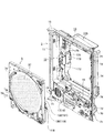
図1はパチンコ機の外枠の一側に本体枠が開かれその本体枠の一側に前面枠が開かれた状態を示す斜視図である。なお、図1においては遊技領域における装飾部材が省略された図を示している。
パチンコ機1は、外枠2、本体枠3、前面枠4、及び遊技盤5等を備えて構成されている。外枠2は、上下左右の木製の枠材によって縦長四角形の枠状に形成され、同外枠2の前側下部には、本体枠3の下面を受ける下受板6を有している。外枠2の前面の片側には、ヒンジ機構7によって本体枠3が前方に開閉可能に装着されている。なお、外枠2は、樹脂やアルミニウム等の軽金属によって形成されていてもよい。
Hereinafter, a pachinko gaming machine (hereinafter simply referred to as a “pachinko machine”) according to an embodiment of the present invention will be described in detail with reference to the drawings.
[Overall Configuration of Pachinko Machine] A description will be given based on FIG.
FIG. 1 is a perspective view showing a state in which a main body frame is opened on one side of an outer frame of a pachinko machine and a front frame is opened on one side of the main body frame. Note that FIG. 1 shows a view in which the decorative member in the game area is omitted.
The pachinko machine 1 includes an outer frame 2, a main body frame 3, a front frame 4, a game board 5, and the like. The outer frame 2 is formed into a vertically long rectangular frame shape by upper, lower, left, and right wooden frame members, and has a lower receiving plate 6 that receives the lower surface of the main body frame 3 at the front lower portion of the outer frame 2. On one side of the front surface of the outer frame 2, the main body frame 3 is attached by a hinge mechanism 7 so as to be opened and closed forward. The outer frame 2 may be formed of a light metal such as resin or aluminum.

[本体枠の構成について] 図2及び図4に基づき説明する。
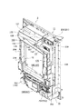
図2はパチンコ機1の前側全体を示す正面図であり、図4はパチンコ機1の本体枠3と遊技盤5とを分離して斜め右上前方から示す斜視図である。
本体枠3は、前枠体11、遊技盤装着枠12及び機構装着体13を合成樹脂材によって一体成形することで構成されている。本体枠3の前枠体11は、外枠2(図1参照)の前側の下受板6を除く外郭形状に対応する大きさの矩形枠状に形成されている。そして、前枠体11の片側の上下部には、本体枠側ヒンジ具15が固定されており、外枠2の片側の上下部に固定された外枠側ヒンジ具14に対してヒンジピン及びヒンジ孔によって開閉回動可能に装着されている。すなわち、外枠側ヒンジ具14、本体枠側ヒンジ具15、ヒンジピン及びヒンジ孔によってヒンジ機構7が構成されている。
[Configuration of Main Body Frame] A description will be given based on FIGS. 2 and 4.
2 is a front view showing the entire front side of the pachinko machine 1, and FIG. 4 is a perspective view showing the main body frame 3 and the game board 5 of the pachinko machine 1 separated obliquely from the upper right front.
The main body frame 3 is configured by integrally molding the front frame body 11, the game board mounting frame 12, and the mechanism mounting body 13 with a synthetic resin material. The front frame body 11 of the main body frame 3 is formed in a rectangular frame shape having a size corresponding to the outer shape excluding the support plate 6 on the front side of the outer frame 2 (see FIG. 1). A main body frame side hinge device 15 is fixed to the upper and lower portions on one side of the front frame body 11, and a hinge pin and a hinge are connected to the outer frame side hinge device 14 fixed to the upper and lower portions on one side of the outer frame 2. It is mounted so that it can be opened and closed by a hole. That is, the hinge mechanism 7 is configured by the outer frame side hinge tool 14, the main body frame side hinge tool 15, the hinge pin, and the hinge hole.

前枠体11の前側において、遊技盤装着枠12よりも下方に位置する前枠体11の前下部左側領域にはスピーカボックス部16が一体に形成され、そのスピーカボックス部16の前側開口部には、同開口部を塞ぐようにしてスピーカ装着板17が装着されている。そして、スピーカ装着板17にはスピーカ18が装着されている。また、前枠体11前面の下部領域内において、その上半部分には発射レール19が傾斜状に装着されている。また、前枠体11前面の下部領域内の下半部分には下部前面板30が装着されている。そして、下部前面板30の前面の略中央部には、遊技球を貯留可能な下皿31が設けられ、右側寄りには操作ハンドル32が設けられ、左側寄りには灰皿33が設けられている。なお、下皿31には、遊技球を下方に排出するための球排出レバー34が配設されている。   On the front side of the front frame body 11, a speaker box portion 16 is integrally formed in the front lower left area of the front frame body 11 positioned below the game board mounting frame 12, and is formed in the front opening portion of the speaker box portion 16. The speaker mounting plate 17 is mounted so as to close the opening. A speaker 18 is mounted on the speaker mounting plate 17. In addition, in the lower region of the front surface of the front frame 11, a firing rail 19 is attached to the upper half of the front frame 11 in an inclined manner. A lower front plate 30 is mounted on the lower half of the lower area of the front surface of the front frame 11. A lower tray 31 capable of storing game balls is provided at a substantially central portion of the front surface of the lower front plate 30, an operation handle 32 is provided on the right side, and an ashtray 33 is provided on the left side. . The lower plate 31 is provided with a ball discharge lever 34 for discharging the game ball downward.

[前面枠の構成について] 図1及び図2に基づき説明する。
前枠体11の前面の片側には、その前枠体11の上端から下部前面板30の上縁にわたる部分を覆うようにして、前面枠4がヒンジ機構36によって前方に開閉可能に装着されている。また、前面枠4の略中央部には、遊技盤5の遊技領域37を前方から透視可能な略円形の開口窓38が形成されている。また、前面枠4の後側には開口窓38よりも大きな矩形枠状をなす窓枠39が設けられ、その窓枠39にはガラス板、透明樹脂板等の透明板50が装着されている。また、前面枠4の前面の略全体は、ランプ等が内設された前面装飾部材によって装飾され、同前面枠4の前面の下部には上皿51が形成されている。詳しくは、開口窓38の周囲において、左右両側部にサイド装飾装置52が、下部に上皿51が、上部に音響電飾装置53が装着されている。サイド装飾装置52は、ランプ基板が内部に配置され且つ合成樹脂材によって形成されたサイド装飾体54を主体として構成されている。サイド装飾体54には、横方向に長いスリット状の開口孔が上下方向に複数配列されており、該開口孔には、ランプ基板に配置された光源に対応するレンズ55が組み込まれている。音響電飾装置53は、透明カバー体56、スピーカ57、スピーカカバー58、及びリフレクタ体(図示しない)等を備え、これらの構成部材が相互に組み付けられてユニット化されている。
[Configuration of Front Frame] A description will be given based on FIGS. 1 and 2.
The front frame 4 is mounted on one side of the front surface of the front frame body 11 so as to cover a portion extending from the upper end of the front frame body 11 to the upper edge of the lower front plate 30 so as to be opened and closed forward by a hinge mechanism 36. Yes. In addition, a substantially circular opening window 38 through which the game area 37 of the game board 5 can be seen through from the front is formed at a substantially central portion of the front frame 4. Further, a window frame 39 having a rectangular frame shape larger than the opening window 38 is provided on the rear side of the front frame 4, and a transparent plate 50 such as a glass plate or a transparent resin plate is mounted on the window frame 39. . Further, substantially the entire front surface of the front frame 4 is decorated by a front decoration member in which a lamp or the like is provided, and an upper plate 51 is formed at the lower part of the front surface of the front frame 4. Specifically, around the opening window 38, a side decoration device 52 is mounted on the left and right sides, an upper plate 51 is mounted on the lower portion, and an acoustic decoration device 53 is mounted on the upper portion. The side decoration device 52 is mainly configured by a side decoration body 54 in which a lamp substrate is disposed and formed of a synthetic resin material. A plurality of slit-like opening holes that are long in the horizontal direction are arranged in the side decoration body 54 in the vertical direction, and a lens 55 corresponding to a light source disposed on the lamp substrate is incorporated in the opening hole. The acoustic illumination device 53 includes a transparent cover body 56, a speaker 57, a speaker cover 58, a reflector body (not shown), and the like, and these constituent members are assembled together to form a unit.

[施錠装置の構成について] 図1及び図4に基づき説明する。
前枠体11のヒンジ機構36に対して反対側となる自由端側の後側には、外枠2に対し本体枠3を施錠する機能と、本体枠3に対し前面枠4を施錠する機能とを兼ね備えた施錠装置70が装着されている。すなわち、この実施形態において、施錠装置70は、外枠2に設けられた閉止具71に係脱可能に係合して本体枠3を閉じ状態に施錠する上下複数の本体枠施錠フック72と、前面枠4の自由端側の後側に設けられた閉止具73に係脱可能に係合して前面枠4を閉じ状態に施錠する上下複数の扉施錠フック74と、パチンコ機1の前方から鍵が挿入されて解錠操作可能に、前枠体11及び下部前面板30を貫通して露出されたシリンダー錠75と、を備えている。そして、シリンダー錠75の鍵穴に鍵が挿入されて一方向に回動操作されることで本体枠施錠フック72と外枠2の閉止具71との係合が外れて本体枠3が解錠され、これとは逆方向に回動操作されることで、扉施錠フック74と前面枠4の閉止具73との係合が外れて前面枠4が解錠されるようになっている。
[Configuration of Locking Device] A description will be given based on FIGS. 1 and 4.
A function of locking the main body frame 3 with respect to the outer frame 2 and a function of locking the front frame 4 with respect to the main body frame 3 on the rear side of the free end side opposite to the hinge mechanism 36 of the front frame body 11 The locking device 70 having both of the above is mounted. That is, in this embodiment, the locking device 70 includes a plurality of upper and lower body frame locking hooks 72 that detachably engage with a closing tool 71 provided on the outer frame 2 to lock the body frame 3 in a closed state, From the front of the pachinko machine 1, a plurality of upper and lower door locking hooks 74 that detachably engage with a closing tool 73 provided on the rear side of the front end of the front frame 4 to lock the front frame 4 in a closed state. And a cylinder lock 75 that is exposed through the front frame 11 and the lower front plate 30 so that the key can be inserted and unlocked. Then, a key is inserted into the key hole of the cylinder lock 75 and rotated in one direction, so that the engagement between the main body frame locking hook 72 and the closing tool 71 of the outer frame 2 is released, and the main body frame 3 is unlocked. By rotating in the opposite direction, the engagement between the door locking hook 74 and the closing tool 73 of the front frame 4 is released and the front frame 4 is unlocked.

[遊技盤装着枠及び遊技盤の構成について] 図1、図3、図4、図5、図11、及び図12に基づき説明する。
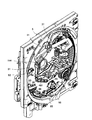
図3は遊技領域37の構成を示す拡大正面図であり、図5はパチンコ機1の後側全体を示す背面図であり、図11及び図12は遊技領域37の構成を示す斜視図である。
図1及び図4に示すように、本体枠3の遊技盤装着枠12は、前枠体11の後側に設けられかつ遊技盤5が前方から着脱交換可能に装着されるようになっている。遊技盤5は、遊技盤装着枠12の前方から嵌込まれる大きさの略四角板状に形成されている。遊技盤5の盤面(前面)には、外レール76と内レール77とを備えた案内レール78が設けられ、その案内レール78の内側に遊技領域37が区画形成されている。なお、発射レール19と案内レール78との間には、所定の隙間が設けられており、発射された遊技球が案内レール78を逆戻りした場合には、その遊技球は、その隙間から排出され下皿31に案内されるように構成されている。また、遊技盤5の前面には、その案内レール78の外側領域において、合成樹脂製の前構成部材79が装着されている。
[Configuration of Game Board Mounting Frame and Game Board] A description will be given based on FIGS. 1, 3, 4, 5, 11, and 12.
3 is an enlarged front view showing the configuration of the game area 37, FIG. 5 is a rear view showing the entire rear side of the pachinko machine 1, and FIGS. 11 and 12 are perspective views showing the configuration of the game area 37. .
As shown in FIGS. 1 and 4, the game board mounting frame 12 of the main body frame 3 is provided on the rear side of the front frame body 11, and the game board 5 is mounted so as to be attachable / detachable from the front. . The game board 5 is formed in a substantially square plate shape having a size to be fitted from the front of the game board mounting frame 12. A guide rail 78 including an outer rail 76 and an inner rail 77 is provided on the board surface (front surface) of the game board 5, and a game area 37 is defined inside the guide rail 78. A predetermined gap is provided between the launch rail 19 and the guide rail 78, and when the launched game ball returns to the guide rail 78, the game ball is discharged from the gap. It is configured to be guided to the lower plate 31. Further, a front structural member 79 made of synthetic resin is attached to the front surface of the game board 5 in the outer region of the guide rail 78.

図3、図11、及び図12に示すように、遊技領域37内には多数の障害釘(図示しない)が所定のゲージ配列をなして設けられているほか、その途中の適宜位置に風車(図示しない)が設けられている。遊技領域37のほぼ中央位置には、センター役物91が配設されており、このセンター役物91のデザインによってパチンコ機1の機種やゲームコンセプト等が特徴付けられている。なお、センター役物91の詳細については後述する。   As shown in FIGS. 3, 11, and 12, a large number of obstacle nails (not shown) are provided in the gaming area 37 in a predetermined gauge arrangement, and a windmill ( (Not shown) is provided. A center accessory 91 is disposed at a substantially central position of the game area 37. The design of the center accessory 91 characterizes the model of the pachinko machine 1, the game concept, and the like. Details of the center accessory 91 will be described later.

また、センター役物91の後方には、抽選結果を演出表示する演出表示装置115が設けられている。演出表示装置115は、装飾図柄画像情報、背景画像情報、キャラクタ画像情報等を合成した画像情報を表示可能な適宜の表示装置が用いられる。本実施の形態では、演出表示装置115として液晶表示装置が用いられている。   Further, an effect display device 115 for effect display of the lottery result is provided behind the center accessory 91. As the effect display device 115, an appropriate display device capable of displaying image information obtained by combining decorative symbol image information, background image information, character image information, and the like is used. In the present embodiment, a liquid crystal display device is used as the effect display device 115.

一方、遊技領域37におけるセンター役物91の下方には、普通図柄始動口96が配置されており、この普通図柄始動口96に遊技球が入球すると、普通抽選を行うとともに、普通図柄を変動表示させるようになっている。また、センター役物91の左側には、普通抽選で当りとなった場合に短時間開放する普通電動役物81を有し、この開放によって遊技球の入賞が可能になる特別図柄始動口82が配設されている。そして、特別図柄始動口82に遊技球が入賞すると、大当り抽選が行われるとともに、特別図柄を変動させるようになっている。ここで、特別図柄始動口82が本発明の入賞口に相当し、普通図柄始動口96が本発明の普通始動口に相当する。   On the other hand, a normal symbol starting port 96 is arranged below the center role 91 in the game area 37. When a game ball enters the normal symbol starting port 96, a normal lottery is performed and the normal symbol is changed. It is supposed to be displayed. Also, on the left side of the center role 91, there is an ordinary electric accessory 81 that is opened for a short time when a winning is made in the normal lottery, and a special symbol start port 82 that allows a game ball to be won by this opening. It is arranged. When a game ball wins the special symbol starting port 82, a big hit lottery is performed and the special symbol is changed. Here, the special symbol starting port 82 corresponds to the winning port of the present invention, and the normal symbol starting port 96 corresponds to the normal starting port of the present invention.

また、遊技領域37には、上記の普通図柄始動口96のさらに下方位置にアタッカ装置98が配設されており、このアタッカ装置98は、開閉部材99の下端部分を軸として開閉部材99を前後方向に開閉動作させることにより下部側大入賞口83を開閉させる。なお、普通図柄始動口96、普通電動役物81、特別図柄始動口82、及びアタッカ装置98等の詳細については後述する。   Further, in the game area 37, an attacker device 98 is disposed at a position further below the normal symbol starting port 96. The attacker device 98 moves the opening / closing member 99 forward and backward with the lower end portion of the opening / closing member 99 as an axis. By opening and closing in the direction, the lower large winning opening 83 is opened and closed. Details of the normal symbol starting port 96, the ordinary electric accessory 81, the special symbol starting port 82, the attacker device 98, and the like will be described later.

また、センター役物91の斜め左下には、普通図柄表示器333(詳細は後述する)として機能する三つのLED84と、普通抽選の保留状態を示す四つのLED85(保留球ランプ)とが設けられている。四つの保留球ランプは、普通抽選において、保留回数分(最大4回)だけ点灯するようになっている。また、これらの下方には、大当り抽選における抽選結果を表示する特別図柄表示器332(詳細は後述する)として機能する四つのLED86が設けられている。例えば、始動入賞を契機として4つのLED86をいろいろなパターンで点滅させることにより、特別図柄の変動状態を表示する。そして、一定の変動時間が終了すると、4つのLED86の点灯・消灯表示パターンによって、確定した特別図柄を停止状態で表示する。つまり、抽選結果情報がLED86の点灯・消灯によって報知される。なおLED86の点灯・消灯による特別図柄の変動表示および停止表示の制御は、主制御基板131(図44参照)により行われる。   Further, three LEDs 84 functioning as a normal symbol display 333 (details will be described later) and four LEDs 85 (holding ball lamps) indicating a normal lottery holding state are provided on the lower left of the center accessory 91. ing. The four holding ball lamps are turned on for the number of holding times (up to 4 times) in the normal lottery. Below these, four LEDs 86 functioning as special symbol indicators 332 (details will be described later) for displaying a lottery result in the big hit lottery are provided. For example, when the start winning prize is triggered, the four LEDs 86 are blinked in various patterns to display the variation state of the special symbol. Then, when a certain fluctuation time is over, the determined special symbols are displayed in a stopped state by the turn-on / off display patterns of the four LEDs 86. That is, the lottery result information is notified by turning on / off the LED 86. The special symbol variation display and stop display control by turning on / off the LED 86 is performed by the main control board 131 (see FIG. 44).

一方、図5に示すように、遊技盤5の後側下部には、その中央部から下部にわたる部分において、各種入賞装置に流入した遊技球を受けかつその遊技球を所定位置まで導く集合樋としての機能とボックス装着部としての機能を兼ね備えたボックス装着台118が設けられている。このボックス装着台118には、音声制御基板、ランプ制御基板等の副制御基板119が収納された副制御基板ボックス130が装着され、その副制御基板ボックス130の後側に重ね合わされた状態で、主制御基板131が収納された主制御基板ボックス132が装着されている。さらに、遊技盤5の後側に対しボックス装着台118、副制御基板ボックス130及び主制御基板ボックス132がそれぞれ装着された状態において、本体枠3の遊技盤装着枠12の前方から遊技盤5を嵌込んで装着できるように、遊技盤5の外郭より外側にはみ出すことなくボックス装着台118、副制御基板ボックス130及び主制御基板ボックス132が配置されている。   On the other hand, as shown in FIG. 5, at the lower rear side of the game board 5, as a collective bag for receiving the game balls flowing into various winning devices and guiding the game balls to a predetermined position in a portion extending from the center portion to the lower portion. A box mounting base 118 having both the above function and the function as a box mounting portion is provided. The box mounting base 118 is mounted with a sub control board box 130 in which a sub control board 119 such as a sound control board and a lamp control board is housed, and is superposed on the rear side of the sub control board box 130. A main control board box 132 in which the main control board 131 is housed is mounted. Further, in a state where the box mounting base 118, the sub control board box 130 and the main control board box 132 are respectively mounted on the rear side of the game board 5, the game board 5 is moved from the front of the game board mounting frame 12 of the main body frame 3. The box mounting base 118, the sub control board box 130, and the main control board box 132 are arranged so as not to protrude outward from the outline of the game board 5 so that they can be fitted and installed.

[本体枠の機構装着体、球タンク及びタンクレールの構成について] 図8及び図9に基づき説明する。
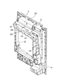
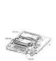
図8はパチンコ機1の本体枠3に各種部材が組み付けられた状態を斜め右上後方から示す斜視図であり、図9は本体枠3単体を斜め右上後方から示す斜視図である。
本体枠3の機構装着体13には、タンク装着部133、レール装着部134、及び払出装置装着部135等がそれぞれ形成され、タンク装着部133には球タンク136が装着されている。球タンク136は、透明な合成樹脂材よりなり、島設備から供給される多数の遊技球が貯留可能な上方に開口する箱形状に形成されている。そして、球タンク136の遊技球の貯留状態が球タンク136の後側壁を透して視認可能となっている。また、球タンク136の底板部137の後側隅部には遊技球を放出する放出口138が形成されるとともに、底板部137は放出口138に向けて下傾する傾斜面に形成されている。
[Configuration of Main Body Frame Mechanism Mounted Body, Ball Tank, and Tank Rail] A description will be given based on FIGS. 8 and 9.
FIG. 8 is a perspective view showing the state in which various members are assembled to the main body frame 3 of the pachinko machine 1 from obliquely upper right rear, and FIG. 9 is a perspective view showing the main body frame 3 alone from obliquely upper right rear.
The mechanism mounting body 13 of the main body frame 3 is formed with a tank mounting portion 133, a rail mounting portion 134, a dispensing device mounting portion 135, and the like, and a ball tank 136 is mounted on the tank mounting portion 133. The ball tank 136 is made of a transparent synthetic resin material, and is formed in a box shape opening upward so that a large number of game balls supplied from the island facility can be stored. The storage state of the game balls in the ball tank 136 is visible through the rear side wall of the ball tank 136. In addition, a discharge port 138 for discharging a game ball is formed at the rear corner of the bottom plate portion 137 of the ball tank 136, and the bottom plate portion 137 is formed on an inclined surface that is inclined downward toward the discharge port 138. .

本体枠3の機構装着体13には、そのタンク装着部133に下方に接近してレール装着部134が一体に形成され、そのレール装着部134にレール構成部材139が装着されることでタンクレール150が構成されるようになっている。すなわち、この実施形態において、レール装着部134は、本体枠3の上部横方向部分が所定深さ凹まされた状態で形成されており、その凹部の奥側壁をタンクレール150の前壁部151とし、その凹部の下縁部に沿って一端(図9に向かって左端)から他端(図9に向かって右端)に向けて下傾する傾斜状のレール棚155が形成されている。そして、レール棚155の横方向に延びる上向き面をレール受け部158としている。   The mechanism mounting body 13 of the main body frame 3 is integrally formed with a rail mounting portion 134 so as to approach the tank mounting portion 133 downward, and the rail component 139 is mounted on the rail mounting portion 134 so that the tank rail 150 is configured. That is, in this embodiment, the rail mounting portion 134 is formed in a state in which the upper lateral portion of the main body frame 3 is recessed by a predetermined depth, and the back side wall of the recess is used as the front wall portion 151 of the tank rail 150. An inclined rail shelf 155 is formed along the lower edge of the concave portion so as to incline downward from one end (left end toward FIG. 9) to the other end (right end toward FIG. 9). An upward surface extending in the lateral direction of the rail shelf 155 is a rail receiving portion 158.

レール装着部134に装着されてタンクレール150を構成するレール構成部材139は、レール装着部134の前壁部151との間にレール通路を構成する後壁部152と、傾斜状をなす下板部と、その下板部の上面の前後方向中央部に沿って突設されレール通路を前後複数列(この実施形態では前後2列)に区画する仕切り壁(いずれも図示しない)とを一体に備えて形成されている。このレール構成部材139は、レール装着部134に対し適宜の取付手段によって装着され、これによって、前後複数列のレール通路を備えたタンクレール150が構成されている。そして、球タンク136の放出口138から放出(自重によって落下)された遊技球がタンクレール150の前後複数列のレール通路の一端部においてそれぞれ受けられた後、遊技球が自重によってレール通路に沿って転動することでレール通路の他端部に向けて流れるようになっている。また、この実施形態において、レール構成部材139は、透明な合成樹脂材より形成され、これによって、レール通路内の遊技球の流れ状態が、レール構成部材139の後壁部152を透して視認可能となっている。   The rail constituting member 139 that is mounted on the rail mounting portion 134 and constitutes the tank rail 150 includes a rear wall portion 152 that forms a rail passage between the rail mounting portion 134 and the front wall portion 151, and an inclined lower plate And a partition wall (both not shown) that project along the center in the front-rear direction of the upper surface of the lower plate part and divide the rail passage into front and rear rows (in this embodiment, front and rear rows). It is formed in preparation. The rail constituting member 139 is attached to the rail attaching portion 134 by an appropriate attachment means, thereby forming a tank rail 150 having a plurality of front and rear rows of rail passages. Then, after the game balls discharged from the discharge port 138 of the ball tank 136 (dropped by its own weight) are received at one end of the rail passages in the front and rear rows of the tank rail 150, the game balls are moved along the rail passage by their own weight. And rolling toward the other end of the rail passage. Further, in this embodiment, the rail component member 139 is formed of a transparent synthetic resin material, whereby the flow state of the game balls in the rail passage is visually recognized through the rear wall portion 152 of the rail component member 139. It is possible.

タンクレール150(レール装着部134)の前壁部151は、遊技盤5の後側に突出する装備品(例えばセンター役物91)における後部の上端部との干渉を避けるため第1空間部を隔てた状態で設けられている。また、この実施形態において、本体枠3の後端部となるレール棚155の後端と、タンクレール150の後壁部は、球タンク136の後側壁と略同一面をなしている。言い換えると、球タンク136の後壁部に対しタンクレール150の後壁部が略同一面となる位置までタンクレール150が遊技盤5の後面より後方に離隔して配置されている。これによって、遊技盤5の後側とタンクレール150の前壁部151との間にセンター役物91の後部との干渉を避けるための第1空間部が設けられるようになっている。   The front wall portion 151 of the tank rail 150 (rail mounting portion 134) has a first space portion to avoid interference with the upper end portion of the rear portion of the equipment (for example, the center accessory 91) protruding rearward of the game board 5. It is provided in a separated state. In this embodiment, the rear end of the rail shelf 155 serving as the rear end portion of the main body frame 3 and the rear wall portion of the tank rail 150 are substantially flush with the rear side wall of the ball tank 136. In other words, the tank rail 150 is arranged behind the rear surface of the game board 5 so that the rear wall portion of the ball tank 136 is substantially flush with the rear wall portion of the ball tank 136. Accordingly, a first space portion for avoiding interference with the rear portion of the center accessory 91 is provided between the rear side of the game board 5 and the front wall portion 151 of the tank rail 150.

また、タンクレール150の上方には、レール通路を流れる遊技球を上下に重なることなく整列させる整流体156がその上部において軸157を中心として揺動可能に装着されている。この整流体156には、その中央部から下部において錘が設けられている。   Above the tank rail 150, a rectifying body 156 for aligning the game balls flowing in the rail passage without overlapping each other is mounted on the upper portion thereof so as to be swingable about the shaft 157. The rectifier 156 is provided with a weight from the center to the bottom.

[払出装置装着部及び球払出装置の構成について] 図8及び図9に基づき説明する。
本体枠3の機構装着体13の片側寄りの上下方向には、次に述べる球払出装置(球払出ユニット)170に対応する縦長の払出装置装着部135が形成されている。払出装置装着部135は、後方に開口部をもつ凹状に形成されている。また、払出装置装着部135の段差状をなす奥壁部(図示しない)の所定位置には、球払出装置170の払出用モータ172(図4参照)が突出可能な開口部173が形成されている。
[Configurations of Dispensing Device Mounting Unit and Ball Dispensing Device] A description will be given based on FIGS. 8 and 9.
A vertically long paying device mounting portion 135 corresponding to a ball paying device (ball paying unit) 170 described below is formed in the vertical direction of one side of the mechanism mounting body 13 of the main body frame 3. The dispensing device mounting portion 135 is formed in a concave shape having an opening on the rear side. In addition, an opening 173 through which a payout motor 172 (see FIG. 4) of the ball payout device 170 can project is formed at a predetermined position on a back wall portion (not shown) having a stepped shape of the payout device mounting portion 135. Yes.

払出装置装着部135の凹部に球払出装置170が装着された状態において、遊技盤5との間には、第1空間部と前後方向に略同一レベルとなる第2空間部が設けられている。これによって、レール通路と球通路とが前後方向に略同一レベルで配置されている。また、本体枠3の後端、すなわち払出装置装着部135の周壁部後端、レール棚155の後端、球タンク136、タンクレール150及び球払出装置170のそれぞれの後面は略同一面をなしている。   In a state where the ball paying device 170 is mounted in the recess of the paying device mounting portion 135, a second space portion is provided between the game board 5 and the first space portion, which is at substantially the same level in the front-rear direction. . Thus, the rail passage and the ball passage are arranged at substantially the same level in the front-rear direction. Further, the rear end of the body frame 3, that is, the rear end of the peripheral wall portion of the dispensing device mounting portion 135, the rear end of the rail shelf 155, the rear surfaces of the ball tank 136, the tank rail 150, and the ball dispensing device 170 are substantially the same surface. ing.

球払出装置170は、払出装置装着部135の凹部と略同じ大きさの縦長のボックス形状をなし、払い出しに関する各種部品が装着されることでユニット化されている。なお、球払出装置170は、払出装置装着部135の凹部の後方開口部から嵌込まれて適宜の取付手段(例えば、弾性クリップ、係止爪、ビス等の取付手段)によって装着されるようになっている。   The ball payout device 170 has a vertically long box shape that is substantially the same size as the recess of the payout device mounting portion 135, and is unitized by mounting various parts related to payout. The ball payout device 170 is fitted from the rear opening of the concave portion of the payout device mounting portion 135 and is mounted by appropriate mounting means (for example, mounting means such as an elastic clip, a locking claw, and a screw). It has become.

また、図示しないが、球払出装置170は、タンクレール150におけるレール通路の出口にそれぞれ連通する流入口を有する球通路が前後複数列(例えば前後2列)に区画されて形成されている。また、その内部に形成された前後複数列の球通路の下流部が二股状に分岐されて前後複数列の賞球及び貸球用球通路と球抜き用球通路とがそれぞれ形成されている。そして賞球及び貸球用球通路と球抜き用球通路との分岐部には、遊技球をいずれかの通路に振り分けて払い出すための回転体よりなる払出部材(図示しない)が正逆回転可能に配設されている。   Although not shown, the ball dispensing device 170 is formed by dividing the ball passages having inflow ports respectively communicating with the outlets of the rail passages in the tank rail 150 into a plurality of front and rear rows (for example, front and rear rows). Also, the downstream portions of the front and rear rows of ball passages formed in the interior are bifurcated to form front and rear rows of prize balls, a ball rental ball passage and a ball removal ball passage. In addition, a payout member (not shown) made of a rotating body for distributing and paying out game balls to any of the passages is rotated in the forward and reverse directions at a branch portion between the winning ball and the ball passage for lending and the ball passage for ball removal. It is arranged to be possible.

[本体枠の後側下部の装備について] 図4及び図5に基づき説明する。
本体枠3の前枠体11の後側において、遊技盤装着枠12よりも下方に位置する前枠体11の後下部領域の片側(図5に向かって左側)には、発射レール19の下傾端部の発射位置に送られた遊技球を発射するための発射ハンマー(図示しない)、その発射ハンマーを作動する発射モータ192等が取付基板193に組み付けられてユニット化された発射装置ユニット194が装着されている。また、前枠体11の後下部領域の略中央部には、電源基板195を収容する電源基板ボックス196が装着され、その電源基板ボックス196の後側に重ね合わされた状態で払出制御基板197を収容する払出制御基板ボックス198が装着されている。払出制御基板197は、遊技球を払い出す数を記憶するRAMを備え、主制御基板131から送信される払出用信号に従って遊技球を払い出す制御信号を中継用回路基板(図示しない)に伝達して払出用モータ172を作動制御するようになっている。
[Equipment on the lower rear side of the main body frame] A description will be given based on Figs.
On the rear side of the front frame body 11 of the main body frame 3, one side (left side in FIG. 5) of the rear lower region of the front frame body 11 located below the game board mounting frame 12 is below the launch rail 19. A launching device unit 194 in which a launching hammer (not shown) for launching a game ball sent to the launching position of the tilted end, a launching motor 192 for operating the launching hammer, etc. are assembled to the mounting substrate 193 and unitized. Is installed. In addition, a power supply board box 196 that houses a power supply board 195 is mounted at a substantially central portion of the rear lower region of the front frame body 11, and the dispensing control board 197 is placed in a state of being superimposed on the rear side of the power supply board box 196. A payout control board box 198 is mounted. The payout control board 197 includes a RAM for storing the number of game balls to be paid out, and transmits a control signal for paying out game balls in accordance with a payout signal transmitted from the main control board 131 to a relay circuit board (not shown). Thus, the operation of the payout motor 172 is controlled.

[後カバー体の構成について] 図5及び図6に基づき説明する。
図6はパチンコ機1の後側全体を右上後方から示す斜視図である。
遊技盤5後面に配置された表示装置制御基板ボックス117(図11参照)及び主制御基板ボックス132の後端部は機構装着体13の中央部に開口された窓開口部に向けて突出している。そして、機構装着体13の窓開口部の一側壁を構成する側壁部と他側壁を構成する払出装置装着部135の片側壁との間には、不透明な合成樹脂材によって略方形の箱形状に形成された後カバー体210がカバーヒンジ機構211によって開閉並びに着脱可能に装着されている。
[Configuration of Rear Cover Body] A description will be given based on FIGS. 5 and 6.
FIG. 6 is a perspective view showing the entire rear side of the pachinko machine 1 from the upper right rear.
The rear end portions of the display device control board box 117 (see FIG. 11) and the main control board box 132 arranged on the rear surface of the game board 5 protrude toward the window opening portion opened in the center portion of the mechanism mounting body 13. . And between the side wall part which comprises one side wall of the window opening part of the mechanism mounting body 13, and the one side wall of the dispensing device mounting part 135 which comprises the other side wall, a substantially square box shape is formed by an opaque synthetic resin material. The formed rear cover body 210 is detachably mounted by a cover hinge mechanism 211.

後カバー体210は、略四角形状の後壁部212と、その後壁部212の外周縁から前方に向けて突出された周壁部213とから一体に構成されている。後カバー体210の周壁部213のうち、一側の壁部213aには、機構装着体13の側壁部の上下及び中間の計3箇所に形成されたヒンジ体214のヒンジ孔の上方からそれぞれ着脱可能に嵌込まれるヒンジピン215を下向きに有するヒンジ体216が一体に形成されている。また、後カバー体210の周壁部213のうち、他側の壁部213bには、払出装置装着部135の片側壁に形成された係止孔に弾性的に係合可能な係止爪を有する弾性閉止体217が一体に形成されている。   The rear cover body 210 is configured integrally with a substantially rectangular rear wall portion 212 and a peripheral wall portion 213 that protrudes forward from the outer peripheral edge of the rear wall portion 212. Of the peripheral wall portion 213 of the rear cover body 210, the wall portion 213 a on one side is attached and detached from above the hinge holes of the hinge body 214 formed at a total of three locations above and below the side wall portion of the mechanism mounting body 13. A hinge body 216 having a hinge pin 215 that can be fitted downward is integrally formed. Further, of the peripheral wall portion 213 of the rear cover body 210, the other wall portion 213b has a locking claw that can be elastically engaged with a locking hole formed in one side wall of the dispensing device mounting portion 135. An elastic closing body 217 is integrally formed.

すなわち、後カバー体210は、その上下及び中間のヒンジ体216の各ヒンジピン215が機構装着体13の側壁部のヒンジ体214のヒンジ孔の上方からそれぞれ嵌込まれる。この状態で、ヒンジピン215を中心として後カバー体210が機構装着体13の他側に向けて回動されながら、その弾性閉止体217を払出装置装着部135の片側壁の係止孔に差し込んで弾性的に係合させることで、機構装着体13の後側に後カバー体210が閉じ状態で保持される。そして、後カバー体210によって、遊技盤5後面の表示装置制御基板ボックス117(図11参照)全体及び主制御基板ボックス132の略中間部から上端にわたる部分が後カバー体210によって覆われるようになっている。これによって、主制御基板ボックス132の上部に露出された主制御基板131の基板コネクタ(主として表示装置制御基板116と接続するための基板コネクタ)が後方から視認不能に隠蔽されている。   That is, in the rear cover body 210, the hinge pins 215 of the upper and lower and intermediate hinge bodies 216 are fitted from above the hinge holes of the hinge body 214 on the side wall portion of the mechanism mounting body 13. In this state, the rear cover body 210 is rotated toward the other side of the mechanism mounting body 13 around the hinge pin 215, and the elastic closing body 217 is inserted into the locking hole on one side wall of the dispensing device mounting portion 135. The rear cover body 210 is held in the closed state on the rear side of the mechanism mounting body 13 by being elastically engaged. Then, the rear cover body 210 covers the entire display device control board box 117 (see FIG. 11) on the rear surface of the game board 5 and a portion extending from the substantially middle portion to the upper end of the main control board box 132 by the rear cover body 210. ing. As a result, the board connector (mainly the board connector for connecting to the display apparatus control board 116) of the main control board 131 exposed at the upper part of the main control board box 132 is hidden from view from behind.

また、主制御基板ボックス132の略中間部から下端にわたる部分は後カバー体210によって覆われることなく露出されている。そして、主制御基板ボックス132の下部には、その主制御基板131上に配置された検査用コネクタ218が露出されており、後カバー体210が閉じられた状態で主制御基板131上の検査用コネクタ218に基板検査装置(図示しない)を接続して検査可能となっている。   Further, a portion from the substantially middle portion to the lower end of the main control board box 132 is exposed without being covered by the rear cover body 210. The inspection connector 218 disposed on the main control board 131 is exposed below the main control board box 132, and the inspection connector on the main control board 131 is closed with the rear cover body 210 closed. A board inspection device (not shown) can be connected to the connector 218 for inspection.

後カバー体210には、多数の放熱孔230、231、232、233が貫設されており、これら多数の放熱孔230、231、232、233から内部の熱が放出されるようになっている。この実施形態において、後カバー体210には、その周壁部213から後壁部212に延びる多数のスリット状の放熱孔230が貫設され、後壁部212の略中間高さ位置から上部においては多数の長円形、楕円形等の放熱孔231が貫設され、後壁部212の下部には多数の長円形、楕円形等の放熱孔232と所定数の横長四角形状の放熱孔233が貫設されている。   A large number of heat radiation holes 230, 231, 232, and 233 are provided in the rear cover body 210, and internal heat is released from these many heat radiation holes 230, 231, 232, and 233. . In this embodiment, the rear cover body 210 is provided with a large number of slit-like heat radiation holes 230 extending from the peripheral wall portion 213 to the rear wall portion 212, and from the substantially middle height position of the rear wall portion 212 to the upper portion. A large number of elliptical, elliptical, etc. heat radiation holes 231 are provided therethrough, and a large number of elliptical, elliptical, etc. heat radiation holes 232 and a predetermined number of horizontally elongated rectangular heat radiation holes 233 pass through the lower portion of the rear wall 212. It is installed.

また、横長四角形状の放熱孔233は、主制御基板ボックス132の封印ねじ(封印部材)によって封印される複数の並列状の封印部235の列の大きさ及び配設位置に対応する大きさ及び位置に貫設されている。これによって、不透明な後カバー体210が閉じられた状態であっても、主制御基板ボックス132の複数の並列状の封印部235が放熱孔233の部分において視認可能に露出される。このため、後カバー体210が閉じられた状態であっても、主制御基板ボックス132の封印部235の封印状態を容易に視認することができる。また、不透明な合成樹脂材は、透明な合成樹脂材と比べ、リサイクル使用される合成樹脂材を材料として用いることが容易であるため、後カバー体210を安価に製作することができる。   Further, the horizontally long rectangular heat radiation holes 233 have a size corresponding to the size and arrangement position of a plurality of parallel seal portions 235 sealed by the seal screws (sealing members) of the main control board box 132. It penetrates the position. As a result, even when the opaque rear cover body 210 is closed, the plurality of parallel sealing portions 235 of the main control board box 132 are exposed so as to be visible at the portion of the heat radiation hole 233. For this reason, even when the rear cover body 210 is closed, the sealing state of the sealing portion 235 of the main control board box 132 can be easily visually confirmed. Further, since the opaque synthetic resin material can be easily used as a synthetic resin material that is recycled compared to the transparent synthetic resin material, the rear cover body 210 can be manufactured at low cost.

後カバー体210の周壁部213のうち、上側壁部213Cの所定位置(この実施形態では左右2箇所)には、電源コード(図示しない)を適宜に折り畳んだ状態で保持する略C字状でかつ弾性変形可能なコード保持体237が上方のタンクレール150の後壁面(レール構成部材139の後壁面)に向けて延出されている。このコード保持体237の先端部には、同コード保持体237を弾性変形させて電源コードを取り外すためのつまみが形成されている。   Of the peripheral wall portion 213 of the rear cover body 210, a predetermined position (two places on the left and right in this embodiment) of the upper wall portion 213C is substantially C-shaped to hold a power cord (not shown) in an appropriately folded state. An elastically deformable cord holder 237 extends toward the rear wall surface of the upper tank rail 150 (the rear wall surface of the rail component 139). A knob for removing the power cord by elastically deforming the cord holder 237 is formed at the tip of the cord holder 237.

電源コードは、その一端が分電基板238の基板コネクタ239に取り外し可能に接続され、他端の電源プラグが電源コンセントに差し込まれる。前記したように、後カバー体210にコード保持体237を一体に形成して電源コードを保持することで、パチンコ機を運搬・保管する際に電源コードがぶらついて邪魔になったり、異物に引っ掛かる不具合を防止することができる。   One end of the power cord is detachably connected to the board connector 239 of the distribution board 238, and the power plug at the other end is inserted into a power outlet. As described above, the cord holder 237 is integrally formed on the rear cover body 210 and the power cord is held, so that the power cord hangs and gets caught by foreign objects when the pachinko machine is transported and stored. Problems can be prevented.

[本体枠の後側下部の下皿用球誘導体等の構成について] 図2及び図7に基づき説明する。
図7は、図6に示すパチンコ機1の斜視図から後ろカバー210及び各種制御基板等を取り外した状態を示す斜視図である。
本体枠3の後下部領域の他側寄り部分(ヒンジ寄り部分)には、そのスピーカボックス部16の後段差部の凹み部分において下皿用球誘導体253が装着されている。この下皿用球誘導体253は、球払出装置170の賞球及び貸球用球通路から上皿連絡路(図示しない)を経て上皿51に払い出された遊技球が満杯になったときに、上皿連絡路の遊技球を下皿31に導くためのものである。
[Configuration of Sphere Derivative for Lower Dish, etc. at Rear Lower Part of Main Body Frame] A description will be given based on FIGS. 2 and 7.
FIG. 7 is a perspective view showing a state in which the rear cover 210 and various control boards are removed from the perspective view of the pachinko machine 1 shown in FIG.
A lower dish ball derivative 253 is attached to the other side portion (hinge portion) of the rear lower region of the main body frame 3 in the recessed portion of the rear step portion of the speaker box portion 16. The lower tray ball derivative 253 is used when the game balls paid out to the upper plate 51 through the upper plate connection path (not shown) from the award and rental ball passages of the ball dispensing device 170 are full. The game ball on the upper plate communication path is for guiding the game ball to the lower plate 31.

なお、この実施形態において、下皿用球誘導体253の後壁外面には、インタフェース基板252を収納している基板ボックス254が装着されている。なお、インタフェース基板252は、パチンコ機1に隣接して設置される球貸機と払出制御基板197との間に介在され、球貸に関する信号を球貸機と払出制御基板197との間で送受信可能に電気的に接続するようになっている。   In this embodiment, a board box 254 that houses the interface board 252 is mounted on the outer surface of the rear wall of the lower dish ball derivative 253. The interface board 252 is interposed between the ball lending machine installed adjacent to the pachinko machine 1 and the payout control board 197, and transmits / receives a signal related to ball lending between the ball lending machine and the payout control board 197. Electrical connection is possible.

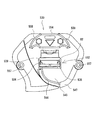
[センター役物の具体的な構成について] 図11乃至図16に基づき説明する。
図11は遊技領域37を斜め右上前方から示す斜視図であり、図12は遊技領域37を斜め左上前方から示す斜視図であり、図13はセンター役物91を示す正面図であり、図14はセンター役物91の前側ユニット120と後側ユニット121とを分離した状態を示す分解斜視図であり、図15は前側ユニット120を機能単位で分離した状態を示す分解斜視図であり、図16は後側ユニット121を機能単位で分離した状態を示す分解斜視図である。
[Specific Configuration of Center Accompaniment] A description will be given based on FIGS. 11 to 16.
11 is a perspective view showing the game area 37 from the diagonally upper right front, FIG. 12 is a perspective view showing the game area 37 from the diagonally upper left front, FIG. 13 is a front view showing the center accessory 91, and FIG. FIG. 15 is an exploded perspective view showing a state in which the front unit 120 and the rear unit 121 of the center accessory 91 are separated, and FIG. 15 is an exploded perspective view showing a state in which the front unit 120 is separated in functional units. FIG. 5 is an exploded perspective view showing a state in which the rear unit 121 is separated into functional units.

図11及び図12に示すように、センター役物91は、額縁状の外観を呈しており、遊技領域37の中央に配設されるとともに、上側から右側に亘る外周部分が、遊技領域37の右側周縁まで延出されている。つまり、センター役物91の右側には、実質的な遊技領域37が形成されておらず、遊技球が通過しないようになっている。なお、センター役物91の大きさは特に限定されるものではないが、本例では、遊技領域37全体の約2/3を占める極めて大きな役物として構築されている。   As shown in FIGS. 11 and 12, the center accessory 91 has a frame-like appearance, and is arranged in the center of the game area 37, and the outer peripheral portion extending from the upper side to the right side is the game area 37. It extends to the right edge. That is, the substantial game area 37 is not formed on the right side of the center accessory 91 so that the game ball does not pass through. Although the size of the center accessory 91 is not particularly limited, in this example, the center accessory 91 is constructed as an extremely large accessory that occupies about 2/3 of the entire game area 37.

図13乃至図16に示すように、センター役物91は、前側に配置される前側ユニット120と、その後側に配置される後側ユニット121とに大別されている。前側ユニット120は、遊技領域37から前方に突出した状態で配設されており、遊技領域37と内部空間とを区画する装飾フレーム125を備えている。なお、装飾フレーム125の外周面のうち特に左側の部分には、遊技球を誘導するための誘導壁123が形成され、また、装飾フレーム125の中央には表示窓として機能する開口部124が設けられている。   As shown in FIGS. 13 to 16, the center accessory 91 is roughly divided into a front unit 120 disposed on the front side and a rear unit 121 disposed on the rear side. The front unit 120 is disposed in a state of protruding forward from the game area 37 and includes a decorative frame 125 that partitions the game area 37 and the internal space. A guide wall 123 for guiding the game ball is formed on the left side of the outer peripheral surface of the decorative frame 125, and an opening 124 functioning as a display window is provided in the center of the decorative frame 125. It has been.

装飾フレーム125は、表面に装飾が施されており、その左上部には、演出に応じて光を放射する上側電飾体127が配設され、装飾フレーム125の右下部には、上側電飾体127とは別の形態の下側電飾体128が配設されている。さらに、装飾フレーム125の右側には、周面に沿って円弧状に配設された複数の発光手段からなる枠電飾体129が設けられている。   The decoration frame 125 has a decoration on the surface, and an upper electric decoration body 127 that emits light according to the effect is arranged at the upper left part, and an upper electric decoration is arranged at the lower right part of the decoration frame 125. A lower electric decoration 128 having a different form from the body 127 is provided. Further, on the right side of the decorative frame 125, there is provided a frame electric decoration body 129 made up of a plurality of light emitting means arranged in an arc shape along the peripheral surface.

また、装飾フレーム125の上部側は、右上部分が左上部分よりも上方に突出しており、その内側に拡張開口部140が形成されている。この拡張開口部140は、後述する装飾物246や横断誘導部材247を収容する空間として機能しており、開口部124と連通した状態で形成されている。拡張開口部140の左側壁の誘導壁123には、遊技球が入賞可能な大入賞口141が装飾フレーム125の周面を貫通して設けられており、可動片142によって開閉可能となっている。なお、図面では、可動片142によって大入賞口141が閉鎖された状態を示しており、この状態では、大入賞口141に遊技球を入賞させることができないようになっている。可動片142が開放し、大入賞口141に入賞した遊技球は、横断誘導部材247等から構成された誘導通路143によって誘導され、後述する回転式振分装置294に送られる。   Further, on the upper side of the decoration frame 125, the upper right portion protrudes upward from the upper left portion, and an expansion opening 140 is formed inside thereof. The extended opening 140 functions as a space for accommodating a decorative object 246 and a transverse guide member 247 described later, and is formed in a state of communicating with the opening 124. The guide wall 123 on the left side wall of the expansion opening 140 is provided with a large winning opening 141 through which the game ball can be won, penetrating the peripheral surface of the decoration frame 125 and can be opened and closed by the movable piece 142. . Note that the drawing shows a state in which the big prize opening 141 is closed by the movable piece 142, and in this state, the game balls cannot be won in the big prize opening 141. The game ball that has opened the movable piece 142 and won the big prize opening 141 is guided by the guide passage 143 constituted by the cross guide member 247 and the like, and is sent to the rotary sorter 294 described later.

また、装飾フレーム125の左側面には、遊技球が入球可能な流入口144(図12参照)が設けられており、流入口144から入球した遊技球を装飾フレーム125の内部に取り入れることが可能になっている。装飾フレーム125の内側底面には、後述するステージ461から流出する遊技球を、普通図柄始動口96に向かって案内する入賞案内部145が設けられている。   In addition, an inflow port 144 (see FIG. 12) through which a game ball can enter is provided on the left side surface of the decoration frame 125, and the game ball that has entered from the inflow port 144 is taken into the interior of the decoration frame 125. Is possible. On the inner bottom surface of the decoration frame 125, a winning guide section 145 for guiding a game ball flowing out from a stage 461 described later toward the normal symbol starting port 96 is provided.

以下、装飾フレーム125に組みつけられた上記の各構成についてさらに詳細に説明する。   Hereinafter, each of the above-described components assembled to the decorative frame 125 will be described in more detail.

[上側電飾体127について]
上側電飾体127は、図15に示すように、オートバイのライトを模したものであり、発光可能な比較的大型のヘッドランプ部148と、その両側に配置された小型のサイドランプ部149と、ヘッドランプ部148及びサイドランプ部149を支持するランプ支持部160とを有して構成されている。また、これらの下方を覆うように底面から後方に延出された装飾カバー(図示しない)が設けられている。
[About the upper electric body 127]
As shown in FIG. 15, the upper electric body 127 is a model of a motorcycle light, and a relatively large headlamp unit 148 capable of emitting light, and small side lamp units 149 disposed on both sides thereof. And a lamp support portion 160 that supports the head lamp portion 148 and the side lamp portion 149. In addition, a decorative cover (not shown) extending rearward from the bottom surface is provided so as to cover these lower portions.

[下側電飾体128について]
下側電飾体128は、図15に示すように、所定の文字(例えば「爆」)の形状が切り抜かれた文字盤164と、その後方に配置された反射板(図示しない)、及び発光手段(図示しない)とを有して構成されている。つまり、発光手段の光を、反射板によって乱反射させるとともに、その光を文字盤164に形成された文字窓を通して放射させることにより、文字盤164の文字を光らせることを可能にしている。
[About the lower illumination body 128]
As shown in FIG. 15, the lower electrical decoration body 128 includes a dial 164 from which a predetermined character (for example, “explosion”) is cut out, a reflector (not shown) disposed behind the dial 164, and light emission Means (not shown). That is, the light of the light emitting means is diffusely reflected by the reflecting plate, and the light on the dial 164 can be illuminated by radiating the light through the character window formed on the dial 164.

[可動片142及びその駆動機構について]
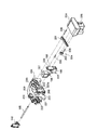
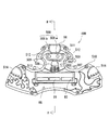
大入賞口141を開閉する可動片142は、上側電飾体127の後方に配設された開閉部材駆動機構184によって回動するように支持されている。つまり、可動片142は、前後方向に延出された支持軸185を中心として回動可能に軸支され、開閉部材駆動機構184によって支持軸185を回動させることにより、起立状態(閉鎖状態)から傾斜状態(開放状態)、または傾斜状態から起立状態に変位させることが可能になっている。開閉部材駆動機構184の詳細について、図17乃至図19に基づいて説明する。図17は可動片142及び開閉部材駆動機構184を斜め左上後方から示す斜視図であり、図18は可動片142及び開閉部材駆動機構184の構成を示す背面図であり、図19は開閉部材駆動機構184の各構成を分離した状態を示す分解斜視図である。
[About the movable piece 142 and its driving mechanism]
The movable piece 142 that opens and closes the grand prize winning opening 141 is supported so as to be rotated by an opening / closing member driving mechanism 184 disposed behind the upper electric ornament 127. That is, the movable piece 142 is pivotally supported around a support shaft 185 extending in the front-rear direction, and is turned upright (closed state) by rotating the support shaft 185 by the opening / closing member drive mechanism 184. It is possible to displace from an inclined state (open state) or from an inclined state to a standing state. Details of the opening / closing member driving mechanism 184 will be described with reference to FIGS. 17 is a perspective view showing the movable piece 142 and the opening / closing member driving mechanism 184 obliquely from the upper left rear, FIG. 18 is a rear view showing the configuration of the movable piece 142 and the opening / closing member driving mechanism 184, and FIG. It is a disassembled perspective view which shows the state which isolate | separated each structure of the mechanism 184. FIG.

開閉部材駆動機構184は、プランジャー186(図19参照)の先端が下方を向くように配設されたソレノイド187と、プランジャー186の先端に取付けられ上下方向に往復運動するブロック状の往復動部材188と、往復動部材188の上面後端部分から上方(すなわちソレノイド186の後側)に向かって延出され往復動部材188と一体成形された延出部189と、延出部189の往復運動を可動片142の支持軸185に伝達し支持軸185を回転させるリンク機構204とを有して構成されている。なお、往復動部材188の左右両側面には、左右外方向へ突出する一対のフランジ225が形成されており、延出部189の上部側には、前後方向に貫通し左右方向に長い長孔205が穿設されている。   The opening / closing member drive mechanism 184 includes a solenoid 187 disposed so that the tip of the plunger 186 (see FIG. 19) faces downward, and a block-like reciprocating motion that is attached to the tip of the plunger 186 and reciprocates vertically. A member 188, an extending portion 189 extending upward from the rear end portion of the upper surface of the reciprocating member 188 (that is, the rear side of the solenoid 186) and integrally formed with the reciprocating member 188, and reciprocation of the extending portion 189. A link mechanism 204 that transmits the motion to the support shaft 185 of the movable piece 142 and rotates the support shaft 185 is configured. Note that a pair of flanges 225 projecting in the left and right outward directions are formed on the left and right side surfaces of the reciprocating member 188, and an elongated hole penetrating in the front-rear direction and extending in the left-right direction on the upper side of the extending portion 189. 205 is drilled.

リンク機構204は、長手方向が延出部189の往復運動方向に対して略垂直になるように配設され、右側端部が回動軸200を介して回動可能に軸支されたアーム部201と、延出部189の上端近傍とアーム部201とを連結し、延出部189の直線往復運動をアーム部201の回動運動に変換する運動変換部材202と、アーム部201の先端側(左側端部)と可動片142の支持軸185とを連結し、アーム部201の回動運動を支持軸185に伝達する双眼鏡形状の回動伝達部材203とから構成されている。なお、運動変換部材202は、アーム部201の軸支部分(すなわち回動軸200が接続された部分)と回動伝達部材203が連結された部分との間に連結されている。また、回動伝達部材203は、連結ピン206を介してアーム部201に連結されるとともに、アーム部201の先端から内側(右方向)に向かって延設されている。また、運動変換部材202は、延出部189の上部に形成された長孔205に挿入されており、延出部189が往復直線運動する際、アーム部201の角度に合わせて左右方向に摺動するようになっている。つまり、アーム部201に対する接続点の位置を変えることなく、延出部189の往復直線運動をアーム部201の回動運動に変換させることを可能にしている。なお、延出部189及びソレノイド187は、アーム部201の回動軸200と可動片142の支持軸185との間に配置されており、開閉部材駆動機構184における上下方向の長さが短くなるように構成されている。   The link mechanism 204 is disposed so that its longitudinal direction is substantially perpendicular to the reciprocating direction of the extending portion 189, and an arm portion whose right end is pivotally supported via the rotation shaft 200. 201, a motion converting member 202 that connects the vicinity of the upper end of the extending portion 189 and the arm portion 201, and converts the linear reciprocating motion of the extending portion 189 into the rotational motion of the arm portion 201, and the distal end side of the arm portion 201 (A left end) and a support shaft 185 of the movable piece 142 are connected to each other, and a binocular-shaped rotation transmission member 203 that transmits the rotation motion of the arm unit 201 to the support shaft 185 is configured. The motion conversion member 202 is coupled between a pivotal support portion of the arm portion 201 (that is, a portion to which the rotational shaft 200 is connected) and a portion to which the rotational transmission member 203 is coupled. The rotation transmitting member 203 is connected to the arm portion 201 via a connecting pin 206 and extends from the tip of the arm portion 201 toward the inside (rightward direction). Further, the motion converting member 202 is inserted into a long hole 205 formed in the upper part of the extending portion 189. When the extending portion 189 reciprocates linearly, the motion converting member 202 slides in the left-right direction according to the angle of the arm portion 201. It comes to move. That is, it is possible to convert the reciprocating linear motion of the extending portion 189 into the rotational motion of the arm portion 201 without changing the position of the connection point with respect to the arm portion 201. The extending portion 189 and the solenoid 187 are disposed between the rotating shaft 200 of the arm portion 201 and the support shaft 185 of the movable piece 142, and the length in the vertical direction of the opening / closing member driving mechanism 184 is shortened. It is configured as follows.

ところで、開閉部材駆動機構184には、ソレノイド187が取付けられた基板183(図15参照)と、ソレノイド187及び往復動部材188を挿通させる透孔208を有し基板183全体を後側から覆う透明の第一ケース209と、その第一ケース209の外面から突出して形成され回動軸200の一端側が挿入される筒状の第一軸受部220と、第一ケース209を貫通するとともに第一ケース209の外面から突出して形成され、支持軸185が挿通される第二軸受部221とが備えられている。つまり、第一ケース209に形成された第一軸受部220によって回動軸200が支持され、第二軸受部221によって可動片142の支持軸185が支持されている。また、第一ケース209の前面側の周縁には、第一ケース209を装飾フレーム125の背面に固定するための複数の取付部222が突出して形成されている。   By the way, the opening / closing member driving mechanism 184 has a substrate 183 (see FIG. 15) to which a solenoid 187 is attached and a through hole 208 through which the solenoid 187 and the reciprocating member 188 are inserted. The first case 209, a cylindrical first bearing portion 220 that protrudes from the outer surface of the first case 209 and is inserted into one end of the rotary shaft 200, and passes through the first case 209 and the first case. And a second bearing portion 221 through which the support shaft 185 is inserted. That is, the rotation shaft 200 is supported by the first bearing portion 220 formed in the first case 209, and the support shaft 185 of the movable piece 142 is supported by the second bearing portion 221. Further, a plurality of attachment portions 222 for fixing the first case 209 to the back surface of the decorative frame 125 are formed on the periphery on the front side of the first case 209 so as to protrude.

また、図19に示すように、第一ケース209における透孔208の左右周縁には、第一ケース209の外面から後方に突出して形成されたガイド部223が設けられている。このガイド部223における左右方向の内寸は、往復動部材188の両側面に形成された一対のフランジ225間の外寸と略一致する大きさ(厳密に言えば外寸よりも僅かに広い大きさ)に形成されており、ガイド部223の内面がフランジ225の側面に当接するようになっている。つまり、左右一対のガイド部223によって往復動部材188における左右方向への動きが規制され、上下方向へのみ摺動するようになっている。   Further, as shown in FIG. 19, guide portions 223 formed to protrude rearward from the outer surface of the first case 209 are provided on the left and right peripheral edges of the through hole 208 in the first case 209. The inner dimension of the guide portion 223 in the left-right direction is substantially the same as the outer dimension between the pair of flanges 225 formed on both side surfaces of the reciprocating member 188 (strictly speaking, slightly larger than the outer dimension). The inner surface of the guide portion 223 comes into contact with the side surface of the flange 225. That is, the left and right movements of the reciprocating member 188 are restricted by the pair of left and right guide portions 223, and slide only in the vertical direction.

また、第一ケース209の外面には、開閉部材駆動機構184全体を覆う透明な第二ケース224(図19参照)が組付けられており、ガイド部223の前面側から透孔208内に突出した支え部223aと第二ケース224の先端面とによって、フランジ225を前後方向に挟持している。つまり、第一ケース209及び第二ケース224を利用して往復動部材188における前後方向の動きも規制されている。なお、第二ケース224の背面には、基板に接続された複数のハーネス(図示しない)を結束するためのハーネス掛止片226が配設されている。   A transparent second case 224 (see FIG. 19) that covers the entire opening / closing member drive mechanism 184 is assembled to the outer surface of the first case 209, and projects into the through hole 208 from the front side of the guide portion 223. The flange 225 is sandwiched in the front-rear direction by the support portion 223a and the distal end surface of the second case 224. That is, the back-and-forth movement of the reciprocating member 188 is also restricted using the first case 209 and the second case 224. A harness latching piece 226 for binding a plurality of harnesses (not shown) connected to the board is disposed on the back surface of the second case 224.

[誘導通路143について]
装飾フレーム125内に配設された誘導通路143について、図14、及び図20〜図23に基づき説明する。図20は誘導通路143の構成を示す拡大斜視図であり、図21は誘導通路143及び装飾物246の構成を示す平面図であり、図22は図21におけるA−A断面及びB−B断面を示す断面図であり、図23は誘導通路143の排出口付近の構成を示す断面図である。
[About the guide passage 143]
The guide passage 143 disposed in the decoration frame 125 will be described with reference to FIGS. 14 and 20 to 23. 20 is an enlarged perspective view showing the configuration of the guide passage 143, FIG. 21 is a plan view showing the configurations of the guide passage 143 and the decoration 246, and FIG. 22 is an AA cross section and a BB cross section in FIG. FIG. 23 is a cross-sectional view showing a configuration in the vicinity of the discharge port of the guide passage 143.

図14及び図20に示すように、誘導通路143は、装飾フレーム125と略同一の突出量となるように配設された透明の管状部材からなり、大入賞口141に入賞した遊技球を装飾物246の前方で横断させる横断誘導部材247と、その横断誘導部材247の下流端に連通し横断誘導部材247によって誘導された遊技球を装飾フレーム125の内周面に沿って誘導する周面誘導部280と、周面誘導部280の下流端に連通し、周面誘導部280によって誘導された遊技球を装飾フレーム125の中心側に向かって略水平方向に誘導する内方向誘導部281と、内方向誘導部281に連通し内方向誘導部281によって誘導された遊技球を装飾フレーム125の奥側に向かって誘導する奥方向誘導部284とを具備して一体的に形成されている。   As shown in FIGS. 14 and 20, the guide passage 143 is made of a transparent tubular member disposed so as to have substantially the same protruding amount as the decoration frame 125, and decorates the game ball won in the grand prize winning opening 141. A transverse guide member 247 that traverses in front of the object 246, and a circumferential guide that guides a game ball guided by the transverse guide member 247 along the inner peripheral surface of the decorative frame 125 in communication with the downstream end of the transverse guide member 247 An inward guide portion 281 that communicates with the portion 280 and the downstream end of the peripheral surface guide portion 280 and guides the game ball guided by the peripheral surface guide portion 280 in a substantially horizontal direction toward the center side of the decorative frame 125; An inward direction guiding portion 284 that communicates with the inward direction guiding portion 281 and guides the game ball guided by the inward direction guiding portion 281 toward the back side of the decorative frame 125 is integrally formed. To have.

横断誘導部材247は、装飾フレーム125の拡張開口部140内を横断しており、右側が下方となるように僅かに傾斜して配置されている。また、横断誘導部材247は、略直線状に延出されており、その内部には遊技球が通過する大きさの通路が形成されている。なお、横断誘導部材247は、透明の部材で形成されており、内部を通過する遊技球、及び横断誘導部材247の後方に配設された装飾物246を、横断誘導部材247を通して視認させることが可能になっている。   The transverse guide member 247 traverses through the expansion opening 140 of the decorative frame 125 and is disposed slightly inclined so that the right side is downward. The transverse guide member 247 extends substantially linearly, and a passage having a size through which a game ball passes is formed inside. Note that the cross guide member 247 is formed of a transparent member, and the game ball passing through the inside and the decoration 246 disposed behind the cross guide member 247 can be viewed through the cross guide member 247. It is possible.

周面誘導部280は、装飾フレーム125における前後方向の厚みと略同等の奥行を有しており、その内部には、流下する遊技球を前後方向にジグザグ状に方向転換する複数の方向変換部282が形成されている。つまり、周面誘導部280に案内された遊技球を、前後方向にジグザグ状に流下させることにより、周面誘導部280における上下方向の長さが比較的短い場合でも、通路の長さを比較的長く形成し、遊技球の挙動を十分に楽しませることを可能にしている。なお、方向変換部282の形状及び配列は特に限定されるものではないが、本例では、内方向に向かって尖った断面略三角形状の外観を呈する複数の方向変換部282を、高さ方向に対し千鳥状となるように、互いに対向する前内面及び後内面から交互に突出させている。また、各方向変換部282の上流側根元部分には、前内面または後内面から僅かに突出した半円柱形状の突起283が設けられており、これにより、遊技球の流下速度を抑制している。   The circumferential surface guide portion 280 has a depth substantially equal to the thickness in the front-rear direction of the decorative frame 125, and a plurality of direction change portions that change the flowing game balls in a zigzag manner in the front-rear direction. 282 is formed. In other words, the game balls guided by the circumferential surface guiding portion 280 flow down in a zigzag shape in the front-rear direction, so that the lengths of the passages are compared even when the vertical length of the circumferential surface guiding portion 280 is relatively short. It is possible to fully enjoy the behavior of the game ball. In addition, although the shape and arrangement | sequence of the direction conversion part 282 are not specifically limited, In this example, the several direction conversion part 282 which exhibits the cross-sectional substantially triangular-shaped external appearance sharpened toward the inner direction is used as a height direction. On the other hand, it protrudes alternately from the front inner surface and the rear inner surface facing each other so as to form a staggered pattern. In addition, a semi-cylindrical protrusion 283 that slightly protrudes from the front inner surface or the rear inner surface is provided at the upstream base portion of each direction changing portion 282, thereby suppressing the flow-down speed of the game ball. .

内方向誘導部281は、装飾フレーム125の中心側に向かって略水平方向に延出されており、横断誘導部材247と同様に、装飾フレーム125と略同一の突出量となるように装飾フレーム125の前側にのみ配置されている。つまり、略直線状に形成されており、その内部には遊技球が通過する大きさの通路が形成されている。なお、内方向誘導部281の前側内面及び後側内面においても、周面誘導部280と同様に、半円柱状の突起283が一定の間隔で配設されており、遊技球の流下速度を抑制するようにしている。ただし、内方向誘導部281には、方向変換部282に相当するものは設けられていない。   The inward guide portion 281 extends in a substantially horizontal direction toward the center side of the decoration frame 125 and, like the transverse guide member 247, the decoration frame 125 has substantially the same protruding amount as the decoration frame 125. It is arranged only on the front side. That is, it is formed in a substantially linear shape, and a passage having a size through which a game ball passes is formed inside. In addition, on the front inner surface and the rear inner surface of the inward guide portion 281, like the peripheral guide portion 280, semi-cylindrical protrusions 283 are arranged at a constant interval to suppress the flow speed of the game ball. Like to do. However, the inward direction guide unit 281 is not provided with a component corresponding to the direction conversion unit 282.

奥方向誘導部284は、装飾フレーム125の前側から奥側に向かって延出された直線状の部材であり、奥方向誘導部284の背面には、遊技球を排出する排出口285が設けられている。すなわち、奥方向誘導部284に到達するまでの間、装飾フレーム125の前面付近で誘導されてきた遊技球が、奥方向誘導部284によって後方に向かって誘導されることになる。このように構成することにより、前方から見る遊技者にとっては、遊技球が一瞬止まっているかのように見えるようになる。特に、奥方向誘導部284の底面が内方向誘導部281の底面よりも垂下されているため、内方向誘導部281及び奥方向誘導部284を前方から見た場合、正面視が、水道の蛇口のように鉤状となる。このため、内方向誘導部281によって誘導された遊技球が、奥方向誘導部284の底面から流出するように見せつつ、遊技球を奥方向に向かって誘導させることが可能となる。したがって、遊技球が止まっているかのような感覚を一層強く喚起させることが可能になる。   The back direction guiding portion 284 is a linear member extending from the front side to the back side of the decoration frame 125, and a discharge port 285 for discharging the game ball is provided on the back surface of the back direction guiding portion 284. ing. In other words, the game ball guided near the front surface of the decoration frame 125 until it reaches the back direction guiding portion 284 is guided backward by the back direction guiding portion 284. By configuring in this way, a player who sees from the front can see the game ball as if it has stopped for a moment. In particular, since the bottom surface of the back direction guiding portion 284 is suspended from the bottom surface of the inward direction guiding portion 281, when the inward direction guiding portion 281 and the back direction guiding portion 284 are viewed from the front, the front view is a faucet of water supply It becomes like a bowl. For this reason, it is possible to guide the game ball in the back direction while making it appear that the game ball guided by the inward guide portion 281 flows out from the bottom surface of the back direction guide portion 284. Therefore, it is possible to evoke a sense that the game ball is stopped more strongly.

また、図23に示すように、奥方向誘導部284の内側底面には、後方に向かって下り勾配の突起部286が形成されており、奥方向誘導部284内で遊技球の勢いが弱くなりすぎた場合でも、突起部286によって遊技球を後方に誘導させることを可能にしている。   Further, as shown in FIG. 23, a projection 286 having a downward slope is formed on the inner bottom surface of the back direction guiding portion 284, and the momentum of the game ball is weakened in the back direction guiding portion 284. Even if it is too much, the projection 286 can guide the game ball backward.

なお、図23に示すように、奥方向誘導部284の下流側には、奥方向誘導部284から排出された遊技球を受取り、所定の振分装置321(詳細は後述する)へ案内する案内通路369が配設されている。ここで、奥方向誘導部284の排出口285は、案内通路369の入球口よりも高い位置に配置されており、排出口285と入球口との間に段差部288が形成されている。つまり、段差を設けることにより、案内通路369から奥方向誘導部284内に遊技球が逆流することを防止している。   As shown in FIG. 23, on the downstream side of the back direction guide unit 284, the game ball discharged from the back direction guide unit 284 is received and guided to a predetermined sorting device 321 (details will be described later). A passage 369 is disposed. Here, the discharge port 285 of the back direction guiding portion 284 is disposed at a position higher than the entrance of the guide passage 369, and a stepped portion 288 is formed between the exit 285 and the entrance. . That is, by providing a step, the game ball is prevented from flowing backward from the guide passage 369 into the back direction guiding portion 284.

ところで、本例では、大入賞口141に遊技球が勢いよく入賞した場合でも、横断誘導部材247内で遊技球をゆっくりと転動させることができるように、横断誘導部材247と大入賞口141との間には、大入賞口141に入賞した遊技球の勢いを抑制する速度低減部材248が介装されている。図22に示すように、速度低減部材248は、大入賞口141に入賞した遊技球を後方に向かって案内する後方ガイド部260と、後方ガイド部260に連通し遊技球を僅かに斜め前方へ落下させる降下ガイド部261と、降下ガイド部261に連通し遊技球を前方に向かって案内する前方ガイド部262とから構成されている。なお、後方ガイド部260及び降下ガイド部261は、誘導通路143とは別のガイド通路形成部材によって形成され、前方ガイド部262は誘導通路143の先端において横断誘導部材247と一体に形成されている。   By the way, in this example, even when the game ball wins the big winning opening 141 vigorously, the transverse guiding member 247 and the big winning opening 141 are arranged so that the gaming ball can slowly roll in the cross guiding member 247. A speed reduction member 248 that suppresses the momentum of the game ball that has won the grand prize winning opening 141 is interposed. As shown in FIG. 22, the speed reducing member 248 communicates with the rear guide portion 260 that guides the game ball that has won the prize winning opening 141 rearward, and the rear guide portion 260 to slightly forward the game ball diagonally forward. The lowering guide part 261 is dropped, and the front guide part 262 communicates with the lowering guide part 261 to guide the game ball forward. The rear guide portion 260 and the lowering guide portion 261 are formed by a guide passage forming member different from the guide passage 143, and the front guide portion 262 is formed integrally with the transverse guide member 247 at the tip of the guide passage 143. .

また、降下ガイド部261には、大入賞口141に入賞した遊技球を検出するための入賞状態検出手段263が配設されており、入賞状態検出手段263での検出信号を出力する信号線が、降下ガイド部261の背面側に設けられたコネクタ(図示しない)に接続されている。   In addition, the lowering guide portion 261 is provided with a winning state detecting means 263 for detecting a game ball won in the big winning opening 141, and a signal line for outputting a detection signal from the winning state detecting means 263 is provided. In addition, it is connected to a connector (not shown) provided on the back side of the lowering guide portion 261.

また、本例では速度低減部材248を前方から遮蔽するための遮蔽カバー264(図14参照)が装飾フレーム125の前面に取付けられており、大入賞口141に入賞した遊技球を、一旦遮蔽することにより、横断誘導部材247に遊技球が出現する際のワクワク感を高めている。また、遮蔽カバー264によって入賞状態検出手段263を遮蔽し、見栄えの低下を防止している。なお、遮蔽カバー264は、装飾フレーム125の一部として機能しており、その後方に配設された発光手段(図示しない)によって遮蔽カバー264全体が光るように構成されている。   Further, in this example, a shielding cover 264 (see FIG. 14) for shielding the speed reduction member 248 from the front is attached to the front surface of the decoration frame 125, and temporarily blocks the game ball won in the big winning opening 141. This enhances the feeling of excitement when a game ball appears on the crossing guide member 247. Further, the winning state detecting means 263 is shielded by the shielding cover 264 to prevent the appearance from deteriorating. The shielding cover 264 functions as a part of the decorative frame 125, and is configured such that the entire shielding cover 264 is illuminated by light emitting means (not shown) arranged behind the decoration frame 125.

[後側ユニット121の概略構成]
一方、後側ユニット121は、図14及び図16に示すように、演出表示装置115を視認可能な開口部291を有する枠状の後側フレーム292と、その後側フレーム292の右上に配置されオートバイを模した形状の装飾物246と、後側フレーム292の右側に配置され、誘導通路143によって誘導された遊技球を振分けて誘導する複合誘導装置293と、複合誘導装置293によって誘導された遊技球を回転体によって振分ける回転式振分装置294と、後側フレーム292の下側に配置され遊技球を左右方向に転動させることが可能な転動装置295と、流入口144に流入した遊技球を転動装置295に誘導する誘導装置296と、転動装置295の後方に配設され、演出としてオートバイのスピードメータを視認させるメータ表示装置297とを具備して構成されている。また、後側フレーム292の開口部291には、開口部291を閉鎖する透明の仕切板298が設けられており、転動装置295とメータ表示装置297とが仕切板298によって仕切られている。以下、後側ユニット121における各構成について詳細に説明する。
[Schematic configuration of rear unit 121]
On the other hand, as shown in FIGS. 14 and 16, the rear unit 121 is arranged at the upper right of the frame-shaped rear frame 292 having an opening 291 through which the effect display device 115 can be visually recognized, and the rear frame 292. A decorative object 246 simulating the shape, a composite guiding device 293 that is arranged on the right side of the rear frame 292 and distributes and guides the gaming ball guided by the guide passage 143, and a gaming ball guided by the composite guiding device 293 A rotary sorter 294 that sorts the game balls by a rotating body, a rolling device 295 that is arranged on the lower side of the rear frame 292 and can roll a game ball in the left-right direction, and a game that flows into the inflow port 144 A guidance device 296 that guides the ball to the rolling device 295, and a mail device that is arranged behind the rolling device 295 to visually recognize a motorcycle speedometer. It is configured by including a display device 297. In addition, a transparent partition plate 298 that closes the opening 291 is provided in the opening 291 of the rear frame 292, and the rolling device 295 and the meter display device 297 are partitioned by the partition plate 298. Hereinafter, each component in the rear unit 121 will be described in detail.

[後側フレーム292について]
後側フレーム292は、前面が開放された略四角形の枠状部材であり、開口部291が形成された板状の背面板300と、背面板300の周縁から前方に延出された側面板301とから構成されている。つまり、上記した各構成が後側フレーム292の内部に収容されるように箱状に形成されている。なお、図示していないが、後側フレーム292の周囲、特に左側方及び右下方には、入賞した遊技球または排出される遊技球を所定の部位に案内するための案内通路構成部材が組付けられるようになっている。
[About the rear frame 292]
The rear frame 292 is a substantially quadrangular frame-shaped member whose front surface is open, and includes a plate-like back plate 300 in which an opening 291 is formed, and a side plate 301 that extends forward from the periphery of the back plate 300. It consists of and. That is, each of the above-described components is formed in a box shape so as to be accommodated in the rear frame 292. Although not shown, a guide passage component for guiding a winning game ball or a discharged game ball to a predetermined portion is assembled around the rear frame 292, particularly on the left side and the lower right side. It is supposed to be.

[装飾物246について]
装飾物246は、装飾フレーム125における拡張開口部140に対応する位置、すなわち横断誘導部材247の後方の空間に配設されている。装飾物246は、オートバイの模型である装飾物本体302と、装飾物本体302における前輪が持ち上がるように装飾物本体302を回動可能に支持する支持軸部(図示しない)と、回転力を発生するモータ303と、モータ303の回転を支持軸部に伝達し支持軸部を回動させるリンク機構(図示しない)とから構成されている。つまり、装飾物本体302は、遊技状態に基づいて変動する可動役物であり、例えば、抽選への期待値が高くなると、モータ303を駆動して通常の走行状態から前輪を持ち上げた走行状態へと切替えるようになっている。なお、装飾物本体302の後方には、装飾物本体302の背景となる背景装飾板304(図13参照)が設けられており、背景装飾板304の表面には装飾性を有する凹凸模様が形成されている。
[About the decoration 246]
The decoration object 246 is disposed at a position corresponding to the expansion opening 140 in the decoration frame 125, that is, in a space behind the transverse guide member 247. The ornament 246 generates a rotational force and a ornament main body 302 that is a model of a motorcycle, a support shaft portion (not shown) that rotatably supports the ornament main body 302 so that a front wheel of the ornament main body 302 is lifted. And a link mechanism (not shown) for transmitting the rotation of the motor 303 to the support shaft portion and rotating the support shaft portion. That is, the ornament main body 302 is a movable accessory that fluctuates based on the gaming state. For example, when the expected value for the lottery increases, the motor 303 is driven to a traveling state in which the front wheels are lifted from the normal traveling state. It is designed to switch. A background decoration plate 304 (see FIG. 13) is provided behind the decoration main body 302 as a background of the decoration main body 302, and an uneven pattern having a decorative property is formed on the surface of the background decoration plate 304. Has been.

[複合誘導装置293について]
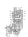
複合誘導装置293の具体的な構成について、図24乃至図29に基づき説明する。図24は複合誘導装置293及び回転式振分装置294を示す斜視図であり、図25は複合誘導装置293及び回転式振分装置294を示す正面図であり、図26は図25におけるC−C断面を示す断面図であり、図27は主に振分装置321付近の構成を示す断面図であり、図28は図25におけるD−D断面を示す断面図であり、図29は図25におけるE−E断面を示す断面図である。
[About compound guidance device 293]
A specific configuration of the composite guiding device 293 will be described with reference to FIGS. 24 is a perspective view showing the composite guiding device 293 and the rotary sorting device 294, FIG. 25 is a front view showing the composite guiding device 293 and the rotary sorting device 294, and FIG. 27 is a cross-sectional view showing a cross section C, FIG. 27 is a cross-sectional view mainly showing a configuration in the vicinity of the sorting apparatus 321, FIG. 28 is a cross-sectional view showing a DD cross section in FIG. 25, and FIG. It is sectional drawing which shows the EE cross section in.

図24〜図26に示すように、複合誘導装置293は、軸心方向が略垂直方向となるように配設された円筒状の円筒部材306と、その円筒部材306内で螺旋状に形成され遊技球を所定の第一領域307まで誘導する内側誘導通路308と、円筒部材306の外周面に沿って螺旋状に形成され遊技球を所定の第二領域309まで誘導する外側誘導通路320と、誘導通路143によって誘導された遊技球、すなわち大入賞口141に入賞した遊技球を、内側誘導通路308と外側誘導通路320とに振分ける振分装置321とを具備して構成されている。つまり、誘導通路143によって誘導された遊技球が、振分装置321によって内側誘導通路308及び外側誘導通路320に振分けられ、夫々螺旋状に形成された通路に沿って旋回しながら、互いに異なる第一領域307及び第二領域309に誘導されるようになっている。特に、互いに区画された二つの誘導通路308,320が内外二重に構成され、しかも螺旋状に形成されているため、互いに区画された比較的長い二つの経路を、装置を大型化させることなく構築することが可能になる。   As shown in FIGS. 24 to 26, the composite guiding device 293 is formed in a cylindrical shape with a cylindrical member 306 disposed so that the axial center direction is substantially vertical, and in a spiral shape within the cylindrical member 306. An inner guide passage 308 for guiding the game ball to the predetermined first region 307, an outer guide passage 320 formed in a spiral shape along the outer peripheral surface of the cylindrical member 306, and guides the game ball to the predetermined second region 309; A distribution device 321 is provided that distributes the game balls guided by the guide passage 143, that is, the game balls won in the big prize opening 141, into the inner guide passage 308 and the outer guide passage 320. In other words, the game balls guided by the guide passage 143 are distributed to the inner guide passage 308 and the outer guide passage 320 by the sorting device 321 and turn along the spiral passages, respectively. It is guided to the area 307 and the second area 309. In particular, since the two guide passages 308 and 320 that are partitioned from each other are configured to be double inside and outside and are formed in a spiral shape, two relatively long paths that are partitioned from each other can be obtained without increasing the size of the apparatus. It becomes possible to build.

また、円筒部材306、内側誘導通路308、及び外側誘導通路320は、いずれも透明の樹脂部材で形成されており、内側誘導通路308及び外側誘導通路320を通過する遊技球の挙動、すなわち旋回している様子を視認させることが可能となっている。   Further, the cylindrical member 306, the inner guide passage 308, and the outer guide passage 320 are all formed of a transparent resin member, and the behavior of the game ball passing through the inner guide passage 308 and the outer guide passage 320, that is, turning. It is possible to make it visible.

また、内側誘導通路308における螺旋の方向と、外側誘導通路320における螺旋の方向とは、互いに逆周りに形成されている。つまり、内側誘導通路308における遊技球の転動方向と、外側誘導通路320における遊技球の転動方向とが、互いに逆向きになるように構成されている。このため、どちらの通路を通過中であるのかを容易に把握させることが可能になるとともに、互いに反対方向に転動する遊技球によって演出の面白みを高めることができる。   Further, the spiral direction in the inner guide passage 308 and the spiral direction in the outer guide passage 320 are formed in opposite directions. That is, the rolling direction of the game ball in the inner guide passage 308 and the rolling direction of the game ball in the outer guide passage 320 are opposite to each other. For this reason, it is possible to easily grasp which passage is being passed, and it is possible to enhance the fun of the production by the game balls rolling in opposite directions.

なお、詳細は後述するが、第二領域309は第一領域307よりも、遊技者にとって有利性の高い領域となっており、遊技球が外側誘導通路320を通過するか否かを特に注目させるようにしている。つまり、遊技球の存在を明瞭に認識させることが可能となる外側誘導通路320を、遊技者が注目すべき通路とすることにより、外側誘導通路320への関心を高めるようにしている。また、有利な第二領域309に向かって誘導する外側誘導通路320の方が長い経路となるため、期待感を次第に高め、その後の展開に対してワクワクさせることが可能となる。   Although the details will be described later, the second area 309 is an area that is more advantageous to the player than the first area 307, and particularly pays attention to whether or not the game ball passes through the outer guide passage 320. I am doing so. That is, the outer guide passage 320 that enables the player to clearly recognize the presence of the game ball is used as a passage that a player should pay attention to, so that interest in the outer guide passage 320 is increased. In addition, since the outer guide passage 320 that leads toward the advantageous second region 309 is a longer route, it is possible to gradually increase the expectation and be excited about the subsequent development.

また、外側誘導通路320の内面には、遊技球の流下速度を抑制する複数の突起325が所定の間隔で形成されている。このため、有利性の高い外側誘導通路320を通過する際、遊技球は、複数の突起325と衝突することとなり、遊技球の勢いが抑制され、ゆっくりと転動するようになる。したがって、遊技球の挙動を十分に視認させることができ、第二領域309で行われる処理と第二領域309に送られるタイミングとの関係に対して、ハラハラドキドキさせることができる。   In addition, a plurality of protrusions 325 are formed on the inner surface of the outer guide passage 320 at predetermined intervals to suppress the flow speed of the game ball. For this reason, when passing through the highly advantageous outer guide passage 320, the game ball collides with the plurality of protrusions 325, the momentum of the game ball is suppressed, and the game ball rolls slowly. Therefore, the behavior of the game ball can be made sufficiently visible, and the relationship between the processing performed in the second area 309 and the timing sent to the second area 309 can be throbbing.

ところで、外側誘導通路320の流出口327は、外側誘導通路320の下部前側に配置されている。このため、外側誘導通路320から第二領域309に流出する際の挙動や排出のタイミングを明確に視認させることができる。特に、外側誘導通路320の流出口327近傍にはクルーン326が設けられており、漏斗状の斜面に沿って旋回させながら排出するように構成されている。したがって、排出されるタイミングが最後まで分かり難くなり、排出されるタイミングに対して一層ハラハラさせることが可能になる。   By the way, the outlet 327 of the outer guide passage 320 is disposed on the lower front side of the outer guide passage 320. For this reason, the behavior and the discharge timing when flowing out from the outer guide passage 320 to the second region 309 can be clearly seen. In particular, a crune 326 is provided in the vicinity of the outlet 327 of the outer guide passage 320, and is configured to discharge while turning along a funnel-shaped slope. Therefore, it becomes difficult to understand the discharge timing until the end, and it becomes possible to make the discharge timing more irritating.

これに対し内側誘導通路308の流出側には、図29に示すように、流出口340までの通路を後方に向かって延出させた延出流出路329が設けられており、流出口340が外側誘導通路320よりも後方に位置するように構成されている。このように、延出流出路329を備えることにより、内側誘導通路308及び外側誘導通路320における螺旋の径が比較的小さい場合でも、内側誘導通路308の流出口340と外側誘導通路320の流出口328とを離間させることが可能となり、第一領域307及び第二領域309において、比較的大型の役物等を配設することが可能となる。   On the other hand, on the outflow side of the inner guide passage 308, as shown in FIG. 29, an extended outflow passage 329 is provided in which the passage to the outflow port 340 is extended rearward. It is configured to be located behind the outer guide passage 320. Thus, by providing the extended outflow passage 329, even when the spiral diameters of the inner guide passage 308 and the outer guide passage 320 are relatively small, the outlet 340 of the inner guide passage 308 and the outlet of the outer guide passage 320 are provided. 328 can be separated from each other, and a relatively large accessory or the like can be disposed in the first region 307 and the second region 309.

一方、図27及び図28に示すように、内側誘導通路308の流入口341aは、振分装置321の左側に延出された流入通路341の先端に形成され、外側誘導通路320の流入口342aは、振分装置321の右側に延出された流入通路342の先端に形成されている。   On the other hand, as shown in FIGS. 27 and 28, the inlet 341 a of the inner guide passage 308 is formed at the tip of the inflow passage 341 extending to the left side of the sorting device 321, and the inlet 342 a of the outer guide passage 320. Is formed at the tip of an inflow passage 342 extending to the right side of the sorting device 321.

振分装置321は、揺動可能に軸支された揺動片363と、プランジャーを往復直線運動させるソレノイド365と、プランジャーの往復直線運動を揺動片363の揺動運動に変換するクランク機構366とを有して構成されている。また、振分装置321に遊技球を案内する案内通路369は、樋状に形成されており、奥方向誘導部284の後端から排出された遊技球を受取って後方に誘導するとともに、その後、Uターンさせ揺動片363の左側真上に案内するようにU字形に形成されている。つまり、ソレノイド365の左側から前方の揺動片363上に向かって流出するように構成されている。そして、揺動片363は、後側から揺動片363上に向かって流出された遊技球を、揺動片363の上面勾配によって、左側に配置された内側誘導通路308の流入口341aと、右側に配置された外側誘導通路320の流入口342aとに振分けるように構成されている。したがって、振分状況を明瞭に視認させることが可能になるとともに、後方から前方に向かって排出された遊技球を左右に振分けるため、揺動片363での跳ね返りがなく滑らかに振分けることができる。   The distribution device 321 includes a swing piece 363 that is pivotally supported, a solenoid 365 that reciprocally moves the plunger, and a crank that converts the reciprocating linear motion of the plunger into a swing motion of the swing piece 363. And a mechanism 366. Further, the guide passage 369 for guiding the game ball to the sorting device 321 is formed in a bowl shape, receives the game ball discharged from the rear end of the back direction guiding portion 284 and guides it backward, and then It is formed in a U shape so as to be U-turned and guided right above the swing piece 363. That is, the solenoid 365 is configured to flow out from the left side toward the front swing piece 363. Then, the swing piece 363 causes the game ball that has flowed out from the rear side toward the swing piece 363 to the inlet 341a of the inner guide passage 308 disposed on the left side due to the upper surface gradient of the swing piece 363, and It is configured to be distributed to the inlet 342a of the outer guide passage 320 arranged on the right side. Accordingly, the distribution situation can be clearly seen and the game balls discharged from the rear to the front are distributed to the left and right, so that the swinging pieces 363 can be smoothly distributed without being rebounded. it can.

なお、揺動片363とソレノイド365との間には、表面が鏡面加工された装飾仕切板380が設けられ、ソレノイド365及びクランク機構366等を装飾仕切板380によって遮蔽している。また、図24及び図25に示すように、振分装置321の前面側は透明なケース382によって覆われ、案内通路369の上方は透明なカバー(図示しない)によって覆われている。つまり、ケース382やカバーを設けることにより、遊技球の逸脱及び外部からの進入を防止している。   A decorative partition plate 380 whose surface is mirror-finished is provided between the swing piece 363 and the solenoid 365, and the solenoid 365 and the crank mechanism 366 are shielded by the decorative partition plate 380. Further, as shown in FIGS. 24 and 25, the front side of the sorting device 321 is covered with a transparent case 382, and the upper portion of the guide passage 369 is covered with a transparent cover (not shown). That is, by providing the case 382 and the cover, the game ball is prevented from escaping and entering from the outside.

さらに、揺動片363の前方下側には、交互に点滅する二つの発光部を有する電飾部381が設けられており、これにより意匠性を高めるとともに、遊技球が二つの経路に振分けられることを喚起させるようにしている。   Further, an electrical decoration unit 381 having two light emitting units alternately flashing is provided on the lower front side of the swing piece 363, thereby improving design and distributing game balls to two paths. I try to arouse that.

[回転式振分装置294について]
続いて、回転式振分装置294について、図24、図26、及び図30〜図33に基づき説明する。図30は回転式振分装置294の構成を示す平面図であり、図31は回転体347を取外した状態を示す平面図であり、図32は図30におけるF−F断面を示す断面図であり、図33は図30におけるG−G断面を示す断面図である。
[Rotary sorter 294]
Next, the rotary sorter 294 will be described with reference to FIGS. 24, 26, and FIGS. 30 is a plan view showing the configuration of the rotary sorter 294, FIG. 31 is a plan view showing a state in which the rotating body 347 is removed, and FIG. 32 is a cross-sectional view showing the FF cross section in FIG. FIG. 33 is a cross-sectional view showing a GG cross section in FIG. 30.

図26及び図30に示すように、回転式振分装置294は、複合誘導装置293の内側誘導通路308または外側誘導通路320によって誘導された遊技球を、回転体347を用いて、有利な状態と不利な状態とに振分けるものである。回転式振分装置294は、凹状の特定領域344、普通領域345、及びリターン領域346を有し、回転可能に支持された円盤状の回転体347と、回転体347を回転させる回転駆動手段343と、回転体347の周囲を囲う外周壁385を有する回転体ケース384とを具備して構成されている。   As shown in FIG. 26 and FIG. 30, the rotary sorter 294 is advantageous in that the game ball guided by the inner guide passage 308 or the outer guide passage 320 of the composite guide device 293 is used with the rotating body 347. And unfavorable conditions. The rotary sorter 294 has a concave specific area 344, a normal area 345, and a return area 346, a disk-shaped rotary body 347 that is rotatably supported, and a rotary drive unit 343 that rotates the rotary body 347. And a rotating body case 384 having an outer peripheral wall 385 surrounding the periphery of the rotating body 347.

また、図31に示すように、回転体ケース384の上面には、回転体347の回転に伴って特定領域344、普通領域345、及びリターン領域346に一時的に連通される流入口367と、内側誘導通路308によって誘導された遊技球を流入口367に案内する案内通路349と、リターン領域346に入球した遊技球をリターン領域346から流出させるリターン流出口389と、リターン流出口389から流出した遊技球を再び流入口367に戻すリターン通路400とが形成されている。さらに、回転体ケース384において回転体347を収容する回転体収容部384aの底面には、特定領域344に入球した遊技球を特定領域344から流出させる第一流出口387と、普通領域345に入球した遊技球を普通領域345から流出させる第二流出口388とが形成されている。また、第一流出口387には、遊技球が第一流出口387から流出されたことを検出する遊技球検出手段(V入賞センサ331)が設けられており、この遊技球検出手段によって遊技球が検出された場合には、遊技者にとって有利となる有利遊技状態が発生するようになっている。
なお、本例では、遊技者に利益が付与される態様として大当り態様が用意されている。具体的には、最大30秒間にわたってアタッカ装置98を一定パターンで開閉させるラウンド動作を15ラウンドまで繰り返すものであり、このようなラウンド動作の繰り返しは「大当り遊技」と称されている。遊技者は、大当り遊技の間に遊技球を下部側大入賞口83に入賞させることで、多くの賞球を獲得することができる。なお、各ラウンド動作は30秒間が経過するか、10個の入賞球がカウントされるかのいずれかの条件を満たすと終了する。また大当り遊技は、ラウンド動作が15回終わると終了となる。
以下、回転式振分装置294における各構成について詳細に説明する。
Further, as shown in FIG. 31, on the upper surface of the rotating body case 384, an inflow port 367 that temporarily communicates with the specific area 344, the normal area 345, and the return area 346 as the rotating body 347 rotates, A guide passage 349 that guides the game ball guided by the inner guide passage 308 to the inflow port 367, a return outflow port 389 that causes the game ball that has entered the return region 346 to flow out from the return region 346, and outflow from the return outflow port 389 A return passage 400 is formed to return the played game ball to the inflow port 367 again. Further, on the bottom surface of the rotator accommodating portion 384 a that accommodates the rotator 347 in the rotator case 384, the first outflow port 387 that causes the game balls that have entered the specific area 344 to flow out of the specific area 344 and the normal area 345 enter. A second outlet 388 is formed to allow the game balls that have been balled to flow out of the normal area 345. The first outlet 387 is provided with game ball detecting means (V winning sensor 331) for detecting that the game ball has flowed out of the first outlet 387, and the game ball is detected by the game ball detecting means. In this case, an advantageous gaming state that is advantageous for the player is generated.
In this example, a jackpot mode is prepared as a mode in which a profit is given to the player. Specifically, a round operation for opening and closing the attacker device 98 in a fixed pattern is repeated up to 15 rounds for a maximum of 30 seconds, and such repetition of the round operation is referred to as “big hit game”. The player can obtain a lot of prize balls by winning the game balls in the lower big prize opening 83 during the big hit game. Note that each round operation ends when either 30 seconds elapses or 10 winning balls are counted. The big hit game ends when the round operation is completed 15 times.
Hereinafter, each component in the rotary sorter 294 will be described in detail.

回転体347は、中央部分が最も高く周縁に向かって緩やかに低くなる笠形状を呈しており、その周縁には、夫々径方向に開口した、一つの特定領域344と、回転体347の回転軸405を中心として特定領域344と対向する位置に形成された一つのリターン領域346と、回転体347及びリターン領域346の間に等間隔で形成された六個の普通領域345とが設けられている。つまり、特定領域344とリターン領域346との位相差が180°となり、それらの領域344,346を繋ぐ線を境界線として、三個の普通領域345が線対象に配設されている。各領域344,345,346の底面には、夫々遊技球が排出可能な貫通孔が形成されており、その貫通孔と回転体収容部384aの底面との組合せによって遊技球が流出される状態と流出されない状態とが切替えられるようになっている。具体的に説明すると、特定領域344における貫通孔は、回転体収容部384aの底面に形成された第一流出口387と合致し、第二流出口388とは合致しない位置に形成され、一方、普通領域345における貫通孔は、回転体収容部384aの底面に形成された第二流出口388と合致し、第一流出口387とは合致しない位置に形成されている。ここで、「合致する」とは、少なくとも遊技球を排出させることができる程度に連通する状態を示しており、「合致しない」とは、譬え重ね合っても連通部分が遊技球の直径よりも小さく遊技球を通過させることのない状態を示している。したがって、特定領域344に遊技球が入球した場合には、その遊技球は回転体347とともに回転し、特定領域344が第一流出口387と合致した際、第一流出口387から流出される。また、普通領域345に遊技球が入球した場合には、その遊技球は回転体347とともに回転し、普通領域345が第二流出口388と合致した際、第二流出口388から流出される。なお、第一流出口387には、V入賞センサ331(図44参照)が配設されており、特定領域344から遊技球が流出したことをV入賞センサ331によって検出するようになっている。また、第二流出口388には、排出センサ313(図44参照)が配設されており、普通領域345から遊技球が流出したことを排出センサ313によって検出するようになっている。   The rotating body 347 has a shade shape in which the central portion is the highest and gradually decreases toward the periphery, and at the periphery, one specific region 344 that opens in the radial direction, and the rotation axis of the rotating body 347. One return region 346 formed at a position facing the specific region 344 around the center 405, and six normal regions 345 formed at equal intervals between the rotating body 347 and the return region 346 are provided. . That is, the phase difference between the specific region 344 and the return region 346 is 180 °, and three normal regions 345 are arranged on the line object with the line connecting these regions 344 and 346 as a boundary line. Through holes through which the game balls can be discharged are formed on the bottom surfaces of the respective regions 344, 345, and 346, and the game balls are discharged by a combination of the through holes and the bottom surface of the rotating body housing portion 384a. The state where it does not flow out can be switched. More specifically, the through hole in the specific region 344 is formed at a position that matches the first outlet 387 formed on the bottom surface of the rotating body accommodating portion 384a and does not match the second outlet 388, whereas The through hole in the region 345 is formed at a position that matches the second outlet 388 formed on the bottom surface of the rotating body accommodating portion 384 a and does not match the first outlet 387. Here, “match” indicates a state where the game balls are communicated with each other at least to the extent that the game balls can be discharged, and “does not match” means that the communication portion is larger than the diameter of the game balls even if they overlap. A small game ball is not allowed to pass through. Therefore, when a game ball enters the specific area 344, the game ball rotates together with the rotating body 347, and flows out from the first outlet 387 when the specific area 344 matches the first outlet 387. Further, when a game ball enters the normal area 345, the game ball rotates together with the rotating body 347, and flows out from the second outlet 388 when the normal area 345 matches the second outlet 388. . A V winning sensor 331 (see FIG. 44) is disposed at the first outlet 387, and the V winning sensor 331 detects that a game ball has flowed out of the specific area 344. Further, a discharge sensor 313 (see FIG. 44) is disposed at the second outlet 388, and the discharge sensor 313 detects that a game ball has flowed out of the normal area 345.

また、特定領域344及び普通領域345の外周縁には、遊技球が各領域344,345から径方向に流出することを防止する円弧状の流出防止壁408が形成されている。つまり、特定領域344及び普通領域345が、回転体ケース384に形成されたリターン流出口389と一致しても、そのリターン流出口389に流出しないように堤が形成されている。換言すれば、リターン領域346における貫通孔は、第一流出口387及び第二流出口388のいずれも合致することはないが、外周縁には流出防止壁408が設けられていないため、リターン流出口389と一致した場合には、リターン流出口389から流出するようになっている。   In addition, arc-shaped outflow prevention walls 408 that prevent the game balls from flowing out from the respective regions 344 and 345 in the radial direction are formed on the outer peripheral edges of the specific region 344 and the normal region 345. In other words, even if the specific region 344 and the normal region 345 coincide with the return outlet 389 formed in the rotating body case 384, the bank is formed so as not to flow out to the return outlet 389. In other words, the through hole in the return region 346 does not match both the first outlet 387 and the second outlet 388, but the outer peripheral edge is not provided with the outflow prevention wall 408. When it matches with 389, it flows out from the return outlet 389.

なお、図33に示すように、リターン流出口389の底面は、流出防止壁408の上面よりも低い位置に形成されリターン通路400に向かって下り勾配となっているため、特定領域344及び普通領域345がリターン流出口389に合致した場合には、流出防止壁408が有効となり、特定領域344及び普通領域345から遊技球が流出することを確実に防止することができる。これに対し、図32に示すように、流入口367の底面は、流出防止壁408の上面よりも高い位置に形成されている。このため、流入口367では流出防止壁408が無効となり、流出防止壁408の有無に拘らず、全ての領域に対し周面開放部分から遊技球を入球させることが可能となる。   As shown in FIG. 33, the bottom surface of the return outlet 389 is formed at a position lower than the top surface of the outflow prevention wall 408 and has a downward slope toward the return passage 400. When 345 matches the return outlet 389, the outflow prevention wall 408 becomes effective, and it is possible to reliably prevent the game ball from flowing out from the specific area 344 and the normal area 345. On the other hand, as shown in FIG. 32, the bottom surface of the inflow port 367 is formed at a position higher than the top surface of the outflow prevention wall 408. For this reason, the outflow prevention wall 408 becomes ineffective at the inflow port 367, and it becomes possible to allow a game ball to enter from all the areas open to the entire area regardless of the presence or absence of the outflow prevention wall 408.

このように、流入口367に到達した遊技球は、回転体347の特定領域344、普通領域345、またはリターン領域346に向かって流入可能な状態となる。つまり、遊技球が流入口367に達しても、その流入口367が回転体347における特定領域344、普通領域345、またはリターン領域346に連通するまではその場所で待機し、回転体347の回転に伴って一時的に連通すると、その特定領域344、普通領域345、またはリターン領域346に入球し、回転体347とともに軸心周りに回転する。そして、特定領域344に入球した遊技球は第一流出口387から流出し、普通領域345に入球した遊技媒体は第二流出口388から流出する。また、特定領域344から遊技球が流出したことに基づいて、遊技者に有利となる有利遊技状態が発生する。   In this way, the game ball that has reached the inflow port 367 is allowed to flow toward the specific area 344, the normal area 345, or the return area 346 of the rotating body 347. That is, even if the game ball reaches the inflow port 367, the game ball waits at that position until the inflow port 367 communicates with the specific area 344, the normal area 345, or the return area 346 in the rotating body 347, and the rotation of the rotating body 347. When the communication is temporarily made, the ball enters the specific area 344, the normal area 345, or the return area 346, and rotates around the axis together with the rotating body 347. Then, the game ball that has entered the specific area 344 flows out from the first outlet 387, and the game medium that has entered the normal area 345 flows out from the second outlet 388. Further, based on the fact that the game ball has flowed out of the specific area 344, an advantageous gaming state that is advantageous to the player occurs.

一方、リターン領域346に入球した遊技球はリターン流出口389から流出し、その後、リターン通路400を通って再び流入口367に戻される。つまり、特定領域344に入球させることができない場合であっても、リターン領域346に入球した場合には、特定領域344に入球させる機会を再び付与することから、遊技者に得した気分を与え、遊技意欲を高めることが可能になる。   On the other hand, the game ball that has entered the return area 346 flows out from the return outlet 389 and then returns to the inlet 367 through the return passage 400. That is, even if it is not possible to enter the specific area 344, if the player enters the return area 346, the opportunity to enter the specific area 344 is given again, so that the player feels And increase the willingness to play.

特に、遊技球を流入口367に戻すためのリターン通路400は、案内通路349とは別の通路で構成されている。このため、最初に流入口367に到達するまでの遊技球の挙動と、再び流入口367に到達する際の遊技球の挙動とを互いに異ならせることができ、異なる挙動によって振分けの単調さを軽減することができる。特に、リターン通路400は、回転体347の外周に沿って形成され、案内通路349は、リターン通路400の外側に配設され、リターン通路400と略並行に形成されている。このため、リターン通路400は、リターン流出口389及び流入口367を最短距離で連通することができ、回転体347付近での遊技球の挙動が必要以上に長くなることによるイライラ感を抑制することができる。また、二つの遊技球を並んで転動させることができるようになり、力動的な挙動を醸し出すことができる。   In particular, the return path 400 for returning the game ball to the inflow port 367 is configured as a path different from the guide path 349. For this reason, the behavior of the game ball until it first reaches the inflow port 367 and the behavior of the game ball when it reaches the inflow port 367 can be made different from each other. can do. In particular, the return passage 400 is formed along the outer periphery of the rotating body 347, and the guide passage 349 is disposed outside the return passage 400 and is formed substantially in parallel with the return passage 400. For this reason, the return passage 400 can communicate the return outlet 389 and the inlet 367 with the shortest distance, and suppresses the feeling of irritation caused by the behavior of the game ball in the vicinity of the rotating body 347 becoming longer than necessary. Can do. Moreover, two game balls can be rolled side by side, and dynamic behavior can be brought out.

また、案内通路349には、保留装置360が介装されており、案内通路349を通過する遊技球を一旦停留させ、その後、所定のタイミングで放出させることができるようになっている。保留装置360は、停留可能な遊技球の保留数を一つのみに制限する球収容部406と、球収容部406を、案内通路349に対して垂直とし遊技球を保留可能とする保留位置、及び案内通路349に対して並行とし保留した遊技球を流出可能とする開放位置との間で回動させる保留駆動機構338(図44参照)とを具備して構成されている。なお、球収容部406が保留位置のときに球収容部406から溢れる遊技球を案内通路349から排出する排出路407が、案内通路349から分岐して形成されている。このように、案内通路349に保留装置360を介在させたことにより、流入口367に到達する遊技球のタイミングが予測し難くなり、特定領域344を狙った特殊な打ち方を抑制することが可能になる。また、リターン通路400には保留装置360が設けられていないため、リターン通路400の傾斜が比較的緩やかであっても、遊技球を円滑に転動させることができる。また、保留装置360に球収容部406が設けられているため、大入賞口141に入賞する遊技球の個数を増やしても、回転体347の特定領域344に入球可能となる遊技球の数を制限することができる。したがって、入賞による遊技者の期待感を高めながらも、遊技店における負担の増大を抑制することが可能となる。   In addition, a holding device 360 is interposed in the guide passage 349 so that a game ball passing through the guide passage 349 can be temporarily stopped and then released at a predetermined timing. The holding device 360 includes a ball storage unit 406 that limits the number of game balls that can be stopped to only one, and a storage position that allows the ball storage unit 406 to be perpendicular to the guide passage 349 and hold a game ball, And a holding drive mechanism 338 (see FIG. 44) that rotates in parallel with the guide passage 349 and rotates to a release position that allows the reserved game ball to flow out. A discharge path 407 for discharging a game ball overflowing from the ball storage portion 406 from the guide passage 349 when the ball storage portion 406 is in the holding position is formed by branching from the guide passage 349. As described above, by interposing the holding device 360 in the guide passage 349, it is difficult to predict the timing of the game ball reaching the inflow port 367, and it is possible to suppress a special way of hitting the specific area 344. become. Further, since the holding device 360 is not provided in the return passage 400, the game ball can be smoothly rolled even if the inclination of the return passage 400 is relatively gentle. In addition, since the ball storage unit 406 is provided in the holding device 360, the number of game balls that can enter the specific area 344 of the rotating body 347 even if the number of game balls to be awarded to the big winning opening 141 is increased. Can be limited. Therefore, it is possible to suppress an increase in the burden at the game store while increasing the player's expectation due to winning.

ところで、図24に示すように、回転体347の各領域に遊技球を入球させる経路として、内側誘導通路308を経由して流入口367から入球させる場合と、外側誘導通路320を経由して回転体347の上面に直接供給する場合とがある。そして、回転体347の上面には、遊技球が入球可能となる普通領域345の個数を制限する入球規制壁421が設けられている。具体的には、図30に示すように、六個の普通領域345のうち、四個の普通領域345の周囲を囲むようにU字形の入球規制壁421が四つ設けられており、二つの普通領域345と、特定領域344及びリターン領域346とにのみ入球させることを可能にしている。すなわち、外側誘導通路320によって第二領域309である回転体347の上面に誘導された場合には、内側誘導通路308によって流入口367に誘導された場合よりも、入球可能となる普通領域345の数が少なくなり、特定領域344またはリターン領域346に入球する確率が高くなる。換言すれば、有利遊技状態が発生する期待値が高くなる。   By the way, as shown in FIG. 24, as a path for entering a game ball into each area of the rotator 347, a ball enters from the inflow port 367 via the inner guide passage 308, and a path through the outer guide passage 320. In some cases, it is directly supplied to the upper surface of the rotating body 347. On the upper surface of the rotator 347, a ball entry restriction wall 421 is provided for restricting the number of normal areas 345 in which game balls can enter. Specifically, as shown in FIG. 30, four U-shaped entrance restriction walls 421 are provided so as to surround the four ordinary areas 345 out of the six ordinary areas 345. It is possible to enter only one normal area 345, a specific area 344, and a return area 346. That is, when guided to the upper surface of the rotator 347, which is the second region 309, by the outer guide passage 320, the normal region 345 where the ball can enter is greater than when guided to the inlet 367 by the inner guide passage 308. And the probability of entering the specific area 344 or the return area 346 increases. In other words, the expected value at which the advantageous gaming state occurs is increased.

ところで、リターン流出口389は、流入口367よりも後方で且つ上方の外周壁385に形成されている。そして、リターン流出口389を流入口367よりも高い位置に形成することにより、リターン通路400を、下流側に向かって下り勾配に形成することが可能となり、リターン流出口389から流出された遊技球を、自重を利用して自然に戻すことが可能になる。ところが、リターン流出口389を流入口367よりも高い位置に形成する場合には、リターン領域346に入球した遊技球を高い位置に持ち上げる必要があり、回転体347の機構が複雑になったり大型化したりする虞がある。そこで、本例では、図26に示すように、回転体347の回転軸405を、回転体347に対して垂設するとともに、上端が下端よりも前側に位置するように前方に傾斜した状態で支持している。つまり、回転体347の上面を前側に傾斜させることにより、回転体347の後側の高さを前側の高さよりも高くし、流入口367からリターン領域346に入球した遊技球を、回転体347の回転力を利用して流入口367よりも高いリターン流出口389まで持ち上げるようにしている。また、これによれば、回転体347の上面を前側に傾斜しているため、流入口367から各領域に遊技媒体が入球する様子や、リターン流出口389からリターン通路400に流出する様子を、明瞭に視認させることが可能となり、回転体347を用いた効果的な演出を容易に行うことができるようになる。   By the way, the return outlet 389 is formed in the outer peripheral wall 385 behind and inward of the inlet 367. Then, by forming the return outlet 389 at a position higher than the inlet 367, the return passage 400 can be formed in a downward slope toward the downstream side, and the game ball that has flowed out of the return outlet 389. Can be returned to nature using its own weight. However, when the return outlet 389 is formed at a position higher than the inlet 367, it is necessary to lift the game ball that has entered the return region 346 to a higher position, and the mechanism of the rotating body 347 becomes complicated or large. There is a risk of becoming. Therefore, in this example, as shown in FIG. 26, the rotating shaft 405 of the rotating body 347 is suspended from the rotating body 347 and tilted forward so that the upper end is located in front of the lower end. I support it. That is, by tilting the upper surface of the rotator 347 forward, the height of the rear side of the rotator 347 is made higher than the height of the front side, and the game ball that has entered the return area 346 from the inflow port 367 The rotational force of 347 is used to lift the return outlet 389 higher than the inlet 367. Further, according to this, since the upper surface of the rotating body 347 is inclined to the front side, a state in which a game medium enters the respective areas from the inflow port 367 and a state in which the game medium flows out from the return outflow port 389 to the return passage 400 is illustrated. Thus, it becomes possible to make it clearly visible, and an effective presentation using the rotating body 347 can be easily performed.

回転軸405を回転させる回転体駆動手段343は、回転力を発生するモータ422、モータ422の回転を回転体347の回転軸405に伝達し、回転体347を一定方向(本例では平面視時計回転方向)に回転させる伝達機構423、モータ422及び回転体ケース384を支持するとともに回転体347の回転軸405を回転可能に支持する支持部材424、及び、回転体347を常時回転させるとともに、回転軸405の回転速度を定期的に異なる速度に切替える速度切替手段409(図44参照)を備えている。   The rotating body driving means 343 that rotates the rotating shaft 405 transmits the rotation of the motor 422 that generates rotational force and the rotation of the motor 422 to the rotating shaft 405 of the rotating body 347, and the rotating body 347 is transmitted in a certain direction (in this example, a plan view clock). (Rotating direction), the support mechanism 423 that supports the transmission mechanism 423, the motor 422, and the rotating body case 384, and supports the rotating shaft 405 of the rotating body 347 so as to be rotatable, and the rotating body 347 are always rotated and rotated. There is provided speed switching means 409 (see FIG. 44) for periodically switching the rotational speed of the shaft 405 to a different speed.

ところで、回転体347の速度が常に一定の場合には、リターン流出口389から流出した遊技球が流入口367に戻る際に、常に同じ領域に入球する可能性があり、これによれば、流入口367に戻る前から、さらにはリターン領域346に入球した時点から、どの領域に戻るのかを把握することが可能となり、リターン領域346を設けたことによる面白みが半減する虞がある。これに対し、本例では、速度切替手段409が備えられ、回転体347の回転速度を定期的に変化させるように構成されている。このため、リターン通路400を通って再び流入口367に戻った遊技球が入球可能となる領域を、随時変化させることが可能になり、ひいてはリターン領域346に入球した際に、その後の遊技球の挙動に注目させることができる。   By the way, when the speed of the rotating body 347 is always constant, there is a possibility that the game ball flowing out from the return outlet 389 may always enter the same region when returning to the inlet 367. Before returning to the inflow port 367 and further when entering the return area 346, it is possible to know which area to return to, and there is a possibility that the interest of providing the return area 346 is reduced by half. On the other hand, in this example, the speed switching means 409 is provided and is configured to periodically change the rotational speed of the rotating body 347. For this reason, it is possible to change the area in which the game ball that has returned to the inflow port 367 through the return passage 400 can enter at any time. As a result, when the player enters the return area 346, You can focus on the behavior of the sphere.

特に、速度切替手段409は、リターン領域346がリターン流出口389に合致した後、リターン領域346から流出された遊技球がリターン通路400を通って流入口367に達するのに要する時間が経過するまでの間における回転体347の回転速度を、定期的に、通常とは異なる速度に変化させている。具体的に説明すると、速度切替手段409は、回転体347を回転させる際、リターン領域346がリターン流出口389に合致する位置を基準点とし、回転体347が半回転のn倍(nは整数:本例では「4」)回転するまでを高速回転させる高速回転モードと、その後、回転体347が半回転のm倍(mは整数:本例では「1」)回転するまでを低速回転させる低速回転モードとを有し、高速回転モード及び低速回転モードを交互に繰り返すようにしている。   In particular, the speed switching unit 409 determines that the time required for the game ball flowing out from the return area 346 to reach the inlet 367 through the return passage 400 after the return area 346 matches the return outlet 389 has elapsed. The rotational speed of the rotating body 347 during the period is periodically changed to a speed different from the normal speed. More specifically, the speed switching means 409 uses the position where the return region 346 matches the return outlet 389 as a reference point when rotating the rotating body 347, and the rotating body 347 is n times half rotation (n is an integer) : "4" in this example) High-speed rotation mode in which high-speed rotation is performed until rotation, and then the rotation of the rotating body 347 is m-times half rotation (m is an integer: "1" in this example). A low-speed rotation mode, and a high-speed rotation mode and a low-speed rotation mode are alternately repeated.

これにより、リターン領域346から流出された遊技球が再び流入口367に到達するまでの間において回転する、回転体347の角速度を確実に変化させることが可能になり、再び入球可能となる領域を定期的に切替えることが可能になる。また、回転速度が一度切り替わると、少なくとも180°回転するまではその速度が継続されるため、回転体347の速度が変化するタイミングを把握させることが可能となり、回転体347の速度と特定領域344に入球する可能性とを関連付けて、遊技球の行方を予測させることが可能となる。換言すれば、回転体347の回転速度にも注目させることが可能となり、振分における興趣を一層高めることが可能になる。なお、この場合、リターン領域346から流出された遊技球が特定領域344に入球する確率は、高速回転モードと低速回転モードとの比率によって決まることとなり、例えば、本例のように、高速回転モードと低速回転モードとの比率を4:1とし、低速回転モード時に特定領域344に入球するように設定した場合は、リターン領域346から流出された遊技球が特定領域344に入球する確率は、1/5となる。つまり、大入賞口141に入賞した遊技球が全て案内通路349を通って流入口367に到達すると仮定した場合、流入口367に到達した遊技球がリターン領域346に入球する確率は1/8となり、その1/5(全体の1/40)が特定領域344に入球することとなる。   As a result, the angular velocity of the rotating body 347 that rotates until the game ball that has flowed out from the return region 346 reaches the inlet 367 again can be changed reliably, and the region where the ball can enter again. Can be switched periodically. In addition, once the rotation speed is switched, the rotation speed is continued until it rotates at least 180 °. Therefore, it is possible to grasp the timing at which the rotation speed of the rotation body 347 changes. It is possible to predict the whereabouts of the game ball in association with the possibility of entering the ball. In other words, it is possible to pay attention to the rotation speed of the rotating body 347, and it is possible to further enhance the interest in the distribution. In this case, the probability that the game ball that has flowed out of the return area 346 enters the specific area 344 is determined by the ratio between the high-speed rotation mode and the low-speed rotation mode. For example, as in this example, the high-speed rotation When the ratio between the mode and the low-speed rotation mode is 4: 1 and the setting is made to enter the specific area 344 in the low-speed rotation mode, the probability that the game ball that has flowed out of the return area 346 enters the specific area 344 Is 1/5. In other words, if it is assumed that all the game balls that have won the big winning opening 141 reach the inflow port 367 through the guide passage 349, the probability that the game balls that have reached the inflow port 367 enter the return area 346 is 1/8. Thus, 1/5 (1/40 of the whole) enters the specific area 344.

[転動装置295及び誘導装置296について]
図14に示すように、後側フレーム292の下部前側には、遊技球を左右方向に揺動させながら落下させるステージ461が設けられている。ステージ461は、奥側の転動面と手前側の転動面とを有しており、手前側の転動面の中央部分には、球導出口461aが設けられている。なお、この球導出口461aは、装飾フレーム125に形成された入賞案内部145と連通しており、ステージ461で転動した遊技球が球導出口461aの中央から放出されると、入賞案内部145を通ることとなり、普通図柄始動口96に入球する可能性が高くなる。なお、ステージ461は半透明の部材から構成されており、ステージ461の下方に配設された発光手段(図示しない)の光をステージ461から放射させる構成となっている。
[About the rolling device 295 and the guidance device 296]
As shown in FIG. 14, a stage 461 is provided on the lower front side of the rear frame 292 to drop the game ball while swinging in the left-right direction. The stage 461 has a rolling surface on the back side and a rolling surface on the near side, and a ball outlet port 461a is provided at the center of the rolling surface on the near side. The ball outlet 461a communicates with a winning guide 145 formed on the decoration frame 125, and when a game ball rolled on the stage 461 is released from the center of the ball outlet 461a, the winning guide 145 is passed, and the possibility of entering the normal symbol starting port 96 is increased. Note that the stage 461 is made of a translucent member and is configured to emit light from a light emitting means (not shown) disposed below the stage 461 from the stage 461.

一方、誘導装置296は、装飾フレーム125の周面に形成された流入口144(図12参照)から入球した遊技球をステージ461に誘導するものであり、本例ではコイル状の形成された通路形成部材296aを縦方向に配置し、流入口144とステージ461とを連通している。つまり、通路形成部材296aは、螺旋状の形状を呈しており、遊技球を螺旋状に回転させながらステージ461に誘導する。また、通路形成部材296aは、後側フレーム292における内側の左側面を塞ぐ閉塞部材424に取付けられ、立設状態で保持されている。なお、閉塞部材424の表面には、細かな凹凸模様が形成されており、遮蔽板としても機能している。   On the other hand, the guide device 296 guides a game ball entered from an inflow port 144 (see FIG. 12) formed on the peripheral surface of the decorative frame 125 to the stage 461. In this example, the guide device 296 is formed in a coil shape. The passage forming member 296a is arranged in the vertical direction, and the inflow port 144 and the stage 461 are communicated with each other. That is, the passage forming member 296a has a spiral shape, and guides the game ball to the stage 461 while rotating the game ball in a spiral manner. The passage forming member 296a is attached to a closing member 424 that closes the inner left side surface of the rear frame 292, and is held in a standing state. Note that a fine uneven pattern is formed on the surface of the closing member 424 and also functions as a shielding plate.

[メータ表示装置297について]
次に、メータ表示装置297について、図14、図34及び図35に基づき説明する。ここで、図34はメータ表示装置297を右上後方から示す斜視図であり、図35はメータ表示装置297を右上前方から示す斜視図である。メータ表示装置297は、後側フレーム292の下部に収容されるとともに昇降可能に支持され、上昇させることにより開口部291内に出現する表示枠部429と、その表示枠部429を昇降させる昇降機構440とを具備して構成されている。
[About meter display device 297]
Next, the meter display device 297 will be described based on FIG. 14, FIG. 34 and FIG. 34 is a perspective view showing the meter display device 297 from the upper right rear, and FIG. 35 is a perspective view showing the meter display 297 from the upper right front. The meter display device 297 is housed in the lower part of the rear frame 292 and supported so as to be lifted and lowered, and when lifted, the display frame part 429 that appears in the opening 291 and a lifting mechanism that lifts and lowers the display frame part 429. 440.

さらに詳しく説明すると、表示枠部429は、左右方向に並んだ一対の円環状の窓枠448を有し、オートバイのスピードメータのケーシングを模した形状を呈している。一対の窓枠448の間には、演出表示装置115とは関係なく発光する第一電飾部449が設けられ、各窓枠448の周囲には、円環状の第二電飾部460が設けられている。第一電飾部449は、上下方向に分離された複数の表示窓を有し、遊技状態に基づいて、発光する表示窓の数が切り替わるようになっている。なお、第一電飾部449及び第二電飾部460は、表示枠部429が出現する場合にのみ点灯し、没入した場合には消灯する。   More specifically, the display frame portion 429 has a pair of annular window frames 448 arranged in the left-right direction, and has a shape imitating a casing of a motorcycle speedometer. Between the pair of window frames 448, a first electric decoration unit 449 that emits light regardless of the effect display device 115 is provided, and an annular second electric decoration unit 460 is provided around each window frame 448. It has been. The first electrical decoration unit 449 has a plurality of display windows separated in the vertical direction, and the number of display windows that emit light is switched based on the gaming state. In addition, the 1st electrical decoration part 449 and the 2nd electrical decoration part 460 are lighted only when the display frame part 429 appears, and are extinguished when immersed.

昇降機構440は、後側フレーム292に固定状態で取付けられたベース部材466と、ベース部材466において横長で前後方向に穿設された左右一対の下側長孔部467と、表示枠部429の底面近傍において横長で前後方向に穿設された左右一対の上側長孔部468と、交差部503が軸支されたX字形のリンク機構469と、そのリンク機構469の下端から前後方向に突出し、夫々の下側長孔部467に対して左右方向に摺動可能な状態で挿入された一対の下側支持ピン480と、リンク機構469の上端から前後方向に突出し、夫々の上側長孔部468に対して左右方向に摺動可能な状態で挿入された一対の上側支持ピン481と、リンク機構469の交差部503を上下動させることにより、表示枠部429を昇降させる昇降駆動手段482とから構成されている。   The elevating mechanism 440 includes a base member 466 fixedly attached to the rear frame 292, a pair of left and right lower long holes 467 that are horizontally long in the base member 466, and a display frame portion 429. A pair of left and right upper elongated holes 468 that are perforated in the vicinity of the bottom surface in the front-rear direction, an X-shaped link mechanism 469 that pivotally supports the intersection 503, and a lower end of the link mechanism 469 project in the front-rear direction. A pair of lower support pins 480 inserted so as to be slidable in the left-right direction with respect to the respective lower long hole portions 467, and project from the upper ends of the link mechanisms 469 in the front-rear direction, and the respective upper long hole portions 468. The display frame portion 429 is moved up and down by moving up and down the pair of upper support pins 481 inserted so as to be slidable in the left-right direction and the crossing portion 503 of the link mechanism 469. And a moving means 482 Prefecture.

特に、ベース部材466は、下側長孔部467が設けられた底面部486と、その底面部486の左右両端から立設された一対の側壁部487とを有し、内部に表示枠部429を収容可能とする収容室が形成されている。また、側壁部487の内側面には、表示枠部429の可動方向を上下方向に案内するガイド部488が設けられている。また、昇降駆動手段482は、回転力を発生するモータ489、及びモータ489の回転を直線運動に変換するピニオン500及びラック501等の運動変換機構によって構成されている。   In particular, the base member 466 includes a bottom surface portion 486 provided with a lower elongated hole portion 467 and a pair of side wall portions 487 erected from both left and right ends of the bottom surface portion 486, and the display frame portion 429 is provided inside. A storage chamber is formed to be capable of storing the battery. Further, a guide portion 488 that guides the movable direction of the display frame portion 429 in the vertical direction is provided on the inner side surface of the side wall portion 487. The elevating drive unit 482 includes a motor 489 that generates a rotational force, and a motion conversion mechanism such as a pinion 500 and a rack 501 that convert rotation of the motor 489 into linear motion.

したがって、昇降駆動手段482によってリンク機構469の交差部503が上昇すると、X字形のリンク機構469は、一対の下側支持ピン480及び一対の上側支持ピン481における夫々間隔(左右方向の間隔)が狭くなり、下側支持ピン480と上側支持ピン481との間隔(リンク機構469における高さ方向の長さ)が長くなるように変形する。すなわち、高さ方向に延びるように変形し、これにより表示枠部429を上昇させる。この際、交差部503の変位を増幅して表示枠部429を変位させることが可能となる。具体的には、本例ではリンク機構469における交差部503の位置が上端と下端との中間部位にあるため、上側支持ピン481の変位量は交差部503の変位量の約二倍となる。換言すれば、昇降駆動手段482におけるラック501のストロークが比較的短い場合でも、表示枠部429をストロークの2倍の長さだけ変位させることが可能になる。また、表示枠部429をX字形のリンク機構469によって支えることから、表示枠部429を安定して昇降させることが可能になる。また、ベース部材466における側壁部487の内側面には、表示枠部429の可動方向を上下方向に案内するガイド部488が設けられているため、表示枠部429を滑らかに昇降させることが可能となる。   Therefore, when the crossing portion 503 of the link mechanism 469 is lifted by the elevating drive means 482, the X-shaped link mechanism 469 has an interval (a horizontal interval) between the pair of lower support pins 480 and the pair of upper support pins 481. It is narrowed and deformed so that the distance between the lower support pin 480 and the upper support pin 481 (the length in the height direction in the link mechanism 469) becomes longer. That is, the display frame portion 429 is raised by being deformed so as to extend in the height direction. At this time, the display frame portion 429 can be displaced by amplifying the displacement of the intersecting portion 503. Specifically, in this example, since the position of the crossing portion 503 in the link mechanism 469 is at an intermediate portion between the upper end and the lower end, the displacement amount of the upper support pin 481 is approximately twice the displacement amount of the crossing portion 503. In other words, even when the stroke of the rack 501 in the elevating drive means 482 is relatively short, the display frame portion 429 can be displaced by a length twice as long as the stroke. Further, since the display frame portion 429 is supported by the X-shaped link mechanism 469, the display frame portion 429 can be moved up and down stably. In addition, since a guide portion 488 that guides the movable direction of the display frame portion 429 in the vertical direction is provided on the inner surface of the side wall portion 487 in the base member 466, the display frame portion 429 can be smoothly raised and lowered. It becomes.

このように、後側フレーム292の下部には昇降可能に支持された表示枠部429が収容されており、表示枠部429を昇降機構440によって上昇させると、表示枠部429は開口部291内に出現する。表示枠部429には、一対の円環状の窓枠448が設けられているため、後側フレーム292の開口部291内に出現すると、窓枠448の内側を通して演出表示装置115の表示画面を視認させることが可能になる。特に、演出表示制御手段443(図53参照)が設けられており、表示枠部429が開口部291内に出現した際、演出表示装置115の表示画面を、窓枠448の内側を通して視認される第一表示領域(図示しない)と、表示枠部429の外側において視認される第二表示領域(図示しない)とに区分けし、第一表示領域及び第二表示領域に対して互いに異なる演出画像を表示させる。特に、本例では,第一表示領域を、右側の窓枠448を通して視認可能となる領域と、左側の窓枠448を通して視認可能となる領域とに区分けし、互いに異なる演出画像を表示させる。例えば、一方の第一表示領域にはスピード(速度)を表示させ、他方の第一表示領域にはエンジンの回転数を表示させるようにしている。   As described above, the display frame portion 429 that is supported so as to be lifted is accommodated in the lower portion of the rear frame 292. When the display frame portion 429 is lifted by the lifting mechanism 440, the display frame portion 429 is placed in the opening 291. Appears on. Since the display frame portion 429 is provided with a pair of annular window frames 448, when the display frame portion 429 appears in the opening 291 of the rear frame 292, the display screen of the effect display device 115 is visually recognized through the inside of the window frame 448. It becomes possible to make it. Particularly, an effect display control means 443 (see FIG. 53) is provided, and when the display frame portion 429 appears in the opening 291, the display screen of the effect display device 115 is visually recognized through the inside of the window frame 448. The display area is divided into a first display area (not shown) and a second display area (not shown) visually recognized outside the display frame portion 429, and different effect images are displayed on the first display area and the second display area. Display. In particular, in this example, the first display area is divided into an area that can be viewed through the right window frame 448 and an area that can be viewed through the left window frame 448, and different effect images are displayed. For example, the speed (speed) is displayed in one first display area, and the engine speed is displayed in the other first display area.

また、領域変位制御手段444(図53参照)を備えており、表示枠部429の上昇途中及び下降途中においては、第一表示領域と第二表示領域との相対位置を、表示枠部429の昇降に追随させて変位させるようにしている。つまり、表示枠部429の内側を通して視認される演出画像を、表示枠部429の可動位置に追随させて変位させることにより、その演出画像が表示枠部429からはみ出さないように制御している。   In addition, an area displacement control unit 444 (see FIG. 53) is provided, and the relative position between the first display area and the second display area is displayed on the display frame part 429 while the display frame part 429 is being raised and lowered. Displacement is made by following up and down. That is, by controlling the effect image that is visually recognized through the inside of the display frame part 429 to follow the movable position of the display frame part 429, the effect image is controlled not to protrude from the display frame part 429. .

このように、表示枠部429の内側と外側とで互いに異なる演出画像を表示させることにより、恰も二つの表示手段があるかのように見せることができ、演出の興趣を高めることが可能になる。特に、表示枠部429の昇降に合わせて第一表示領域が変位するため、表示枠部429の可動中も常に表示枠部429を通して特定の演出を視認させることができ、表示枠部429と演出表示装置115が別々のものであるという印象を喚起させない。また、表示枠部429が出没可能であるため、出現により遊技者に驚きを与えることができる。   Thus, by displaying different effect images on the inner side and the outer side of the display frame part 429, it is possible to make it appear as if there are two display means, and it is possible to enhance the interest of the effect. . In particular, since the first display area is displaced in accordance with the raising and lowering of the display frame part 429, a specific effect can always be visually recognized through the display frame part 429 even when the display frame part 429 is movable. The impression that the display device 115 is separate is not aroused. Further, since the display frame portion 429 can appear and disappear, the player can be surprised by the appearance.

なお、図14及び図16に示すように、後側フレーム292の開口部291を閉塞する透明の仕切板298が設けられており、これにより、ステージ461とメータ表示装置297とが仕切られている。このため、ステージ461を転動する遊技球がメータ表示装置297側に流下すること、すなわち表示枠部429が障害物となることを防止できる。また、仕切板298の右下隅部には、平板状の仕切板298から前方に突出し複合誘導装置293及び回転式振分装置294を覆う透明カバー504が一体的に形成されており、これにより、ステージ461を転動する遊技球が、複合誘導装置293及び回転式振分装置294が配置された領域に進入することを防止している。   As shown in FIGS. 14 and 16, a transparent partition plate 298 that closes the opening 291 of the rear frame 292 is provided, whereby the stage 461 and the meter display device 297 are partitioned. . For this reason, it is possible to prevent the game ball rolling on the stage 461 from flowing down to the meter display device 297 side, that is, the display frame portion 429 being an obstacle. In addition, a transparent cover 504 that protrudes forward from the flat partition plate 298 and covers the composite guiding device 293 and the rotary sorting device 294 is integrally formed at the lower right corner of the partition plate 298, thereby A game ball rolling on the stage 461 is prevented from entering an area where the composite guidance device 293 and the rotary sorting device 294 are arranged.

次に、普通図柄始動口96及びアタッカ装置98を有する入賞口ユニットと、普通電動役物81及び特別図柄始動口82を有する特別始動口ユニット530とについて説明する。   Next, the winning opening unit having the normal symbol starting port 96 and the attacker device 98 and the special starting port unit 530 having the ordinary electric accessory 81 and the special symbol starting port 82 will be described.

[入賞口ユニット499について]
入賞口ユニット499について図36〜図38に基づき説明する。図36は入賞口ユニット499を示す正面図であり、図37は入賞口ユニット499を右上前方から見た斜視図であり、図38は図36図におけるH−H断面図(但し開閉部材99を開放した状態)である。入賞口ユニット499は、遊技盤5(図3参照)の盤面よりも遊技者側に突出して配設された普通図柄始動口96と、普通図柄始動口96の下方に配設された普通入賞装置502と、普通入賞装置502の下方から遊技者側に突出して配設された振分用突起部507と、振分用突起部507の下方に配設されたアタッカ装置98とを具備して構成されている。
[About winning prize unit 499]
The winning opening unit 499 will be described with reference to FIGS. 36 is a front view showing the prize opening unit 499, FIG. 37 is a perspective view of the prize opening unit 499 seen from the upper right front, and FIG. 38 is a cross-sectional view taken along the line HH in FIG. Open state). The winning a prize opening unit 499 includes a normal symbol starting port 96 disposed so as to protrude from the board surface of the game board 5 (see FIG. 3) to the player side, and a normal winning device disposed below the normal symbol starting port 96. 502, a distribution projection 507 that protrudes from the bottom of the normal winning device 502 to the player side, and an attacker device 98 that is disposed below the distribution projection 507. Has been.

ここで、普通図柄始動口96は、遊技領域37(図3参照)を流下する遊技球が通過可能なゲート形の始動口であって、その内部には、普通図柄始動口96に遊技球が通過したことを検出する第一始動口センサ317が設けられている。そして、第一始動口センサ317による遊技球の検出に基づいて普通抽選が行われるようになっている。また、普通図柄始動口96の左右両側には、上面が円弧状の進入阻止部材512が斜め下方に向って延出されており、普通図柄始動口96の外側を通過する遊技球が、振分用突起部507に向って転動することを阻止している。つまり、普通図柄始動口96を通過した遊技球のみを振分用突起部507に到達させることを可能としている。ここで、第一始動口センサ317が本発明の入球状態検出手段に相当する。   Here, the normal symbol start port 96 is a gate-type start port through which a game ball flowing down the game area 37 (see FIG. 3) can pass, and inside the normal symbol start port 96 there is a game ball at the normal symbol start port 96. A first start port sensor 317 is provided for detecting the passage. The normal lottery is performed based on the detection of the game ball by the first start port sensor 317. Further, on both the left and right sides of the normal symbol starting port 96, an arc-shaped entry preventing member 512 is extended obliquely downward, and the game ball passing outside the normal symbol starting port 96 is distributed. Rolling toward the projection 507 is prevented. That is, only the game balls that have passed through the normal symbol starting port 96 can reach the sorting protrusion 507. Here, the first start port sensor 317 corresponds to the ball entry state detecting means of the present invention.

普通入賞装置502は、遊技盤5の盤面に対して開口した普通入賞口500と、普通入賞口500に連通し遊技盤5の奥側に延出された入賞通路501とを有しており、普通入賞口500から入賞通路501内に遊技球を入賞させることが可能になっている。なお、普通入賞口500に遊技球が入賞すると、入賞センサ503(図44参照)によって検出され、これに基づいて所定数の遊技球が払出される。   The normal winning device 502 includes a normal winning opening 500 that opens to the surface of the game board 5 and a winning passage 501 that communicates with the normal winning opening 500 and extends to the back side of the gaming board 5. It is possible to win a game ball in the winning path 501 from the normal winning opening 500. In addition, when a game ball wins the normal winning opening 500, it is detected by a win sensor 503 (see FIG. 44), and a predetermined number of game balls are paid out based on this.

振分用突起部507は、遊技盤5側(普通入賞口500側)に向って僅かに下り勾配に形成された上面傾斜部506を有しており、上面傾斜部506の左右方向略中央部分に落下した遊技球を上面傾斜部506に沿って普通入賞口500へ誘導可能とし、上面傾斜部506の左側端部付近または右側端部付近に落下した遊技球を、上面傾斜部506の側方から排出可能としている。また、振分用突起部507は、普通図柄始動口96の真下に配設され、振分用突起部507の最大横幅が遊技球の外径と略同等で、先端側ほど横幅が狭くなるように平面視先細形状(全体としてホームベース形)に形成されている。   The distribution protrusion 507 has an upper surface inclined portion 506 that is formed with a slight downward slope toward the game board 5 side (ordinary winning port 500 side), and a substantially central portion in the left-right direction of the upper surface inclined portion 506. The game ball that has fallen on the right side can be guided to the normal winning opening 500 along the upper surface inclined portion 506, and the game ball that has dropped to the vicinity of the left end portion or the right end portion of the upper surface inclined portion 506 is moved to the side of the upper surface inclined portion 506. It can be discharged from. The distribution projection 507 is normally disposed directly below the symbol starting port 96 so that the maximum lateral width of the distribution projection 507 is substantially equal to the outer diameter of the game ball, and the lateral width becomes narrower toward the tip side. It is formed into a tapered shape in plan view (as a whole, a home base shape).

アタッカ装置98は、振分用突起部507の下方に配設されており、多量の遊技球を入賞可能とする横長の下部側大入賞口83と、下部側大入賞口83を閉鎖するとともに下端部分を回転軸として前後方向に回動可能に支持された開閉部材99と、開閉部材99を駆動し下部側大入賞口83を閉鎖する閉鎖位置、及び下部側大入賞口83を開放する開放位置の間で回動させるアタッカ駆動機構339(図44参照)とを備えている。なお、図38に示すように、開閉部材99の上面と対向する振分用突起部507の下面513は、遊技盤5側に向って上り勾配に形成されている。これにより、開閉部材99の上端と振分用突起部507の下面513との間隔を、開閉部材99の回動位置に拘らず略一定とすることが可能になり、ひいては開閉部材99の上端と振分用突起部507の下面513との間で遊技球が挟持されること、所謂「球噛み」が発生することを抑制することが可能になる。   The attacker device 98 is disposed below the sorting projection 507, and closes the horizontally long lower prize-winning port 83 and the lower side big prize-winning port 83 that allow a large amount of game balls to be won, and the lower end. An opening / closing member 99 supported so as to be rotatable in the front-rear direction with the portion as a rotation axis, a closed position for driving the opening / closing member 99 to close the lower side big prize opening 83, and an open position for opening the lower side big prize opening 83 An attacker drive mechanism 339 (see FIG. 44). As shown in FIG. 38, the lower surface 513 of the distribution projection 507 facing the upper surface of the opening / closing member 99 is formed in an upward gradient toward the game board 5 side. Thereby, the distance between the upper end of the opening / closing member 99 and the lower surface 513 of the sorting projection 507 can be made substantially constant regardless of the rotation position of the opening / closing member 99, and consequently the upper end of the opening / closing member 99. It is possible to prevent the game ball from being sandwiched between the lower surface 513 of the sorting projection 507 and so-called “ball biting”.

なお、振分用突起部507は可動機構を備えていないため、アタッカ駆動機構339を有するアタッカ装置98を振分用突起部507の下方に設けた場合でも、互いに接近して配置することができ、下部側大入賞口83から普通図柄始動口96までの長さを比較的短くすることができる。   Since the sorting projection 507 does not include a movable mechanism, even when the attacker device 98 having the attacker driving mechanism 339 is provided below the sorting projection 507, they can be arranged close to each other. The length from the lower side large winning opening 83 to the normal symbol starting port 96 can be made relatively short.

ところで、これらの普通図柄始動口96、普通入賞装置502、振分用突起部507、及びアタッカ装置98は、共通のベース板510に取付けられ、一つのユニットとして一体的に構成されている。また、ベース板510における普通図柄始動口96と普通入賞口500との間には、遊技盤5に設けられた障害釘508を挿通させるための釘貫通孔511が穿設されている。つまり、普通図柄始動口96及び普通入賞装置502等を一つのユニットとして一体的に構成するにもかかわらず、遊技盤5に設けられた障害釘508がユニットの内部に配置されることを可能にしている。   By the way, the normal symbol starting port 96, the normal winning device 502, the sorting projection 507, and the attacker device 98 are attached to a common base plate 510 and integrally configured as one unit. In addition, a nail through hole 511 for allowing the obstacle nail 508 provided in the game board 5 to be inserted is formed between the normal symbol starting port 96 and the normal winning port 500 in the base plate 510. That is, the obstacle nail 508 provided on the game board 5 can be arranged inside the unit, although the normal symbol starting port 96 and the normal winning device 502 are integrally formed as one unit. ing.

図36に示すように、障害釘508は、普通図柄始動口96と普通入賞装置502との間に配設され、普通図柄始動口96を通過した遊技球の転動方向を変化させることにより振分用突起部507への落下地点を分散させるものである。特に、本例では、障害釘508は、左右方向に並設される右側障害釘508a及び左側障害釘508bからなり、普通図柄始動口96の中心と普通入賞口500の中心とを結ぶ中心線を基準線とした場合、その基準線から右側障害釘及508aび左側障害釘508bまでの距離が互いに異なるように、右側障害釘508a及び左側障害釘508bが一方に偏って配置されている。このため、それらの障害釘508の間に遊技球を通過させることにより、遊技球の転動方向が大幅に変更されることを抑制できる。つまり、普通図柄始動口96を通過した遊技球の殆ど全てを振分用突起部507の上面に落下させることが可能になる。また、普通図柄始動口96を通過した遊技球を、夫々の障害釘508に順に衝突させることが可能となり、転動方向を確実に変化させることができる。   As shown in FIG. 36, the obstacle nail 508 is disposed between the normal symbol starting port 96 and the normal winning device 502, and swings by changing the rolling direction of the game ball that has passed through the normal symbol starting port 96. The dropping points on the minute projection 507 are dispersed. In particular, in this example, the obstacle nail 508 includes a right obstacle nail 508a and a left obstacle nail 508b arranged side by side in the left-right direction, and a center line connecting the center of the normal symbol start port 96 and the center of the normal winning port 500 is shown. When the reference line is used, the right obstacle nail 508a and the left obstacle nail 508b are biased toward one side so that the distances from the reference line to the right obstacle nail 508a and the left obstacle nail 508b are different from each other. For this reason, it is possible to prevent the rolling direction of the game ball from being changed significantly by passing the game ball between the obstacle nails 508. That is, almost all of the game balls that have passed through the normal symbol starting port 96 can be dropped onto the upper surface of the sorting projection 507. In addition, the game balls that have passed through the normal symbol starting port 96 can collide with the respective obstacle nails 508 in order, and the rolling direction can be reliably changed.

なお、ベース板510は左右方向に延出されており、左右両側には、外方に向って開口した一対の入賞口514が形成されている。また、ベース板510の背面にはケース部材516が取付けられており、このケース部材516の内部に、アタッカ駆動機構339が収容されるとともに、下部側大入賞口83に入賞した遊技球を流出口(図示しない)に誘導する誘導通路(図示しない)が形成されている。また、ケース部材516の上面には、普通入賞装置502の入賞通路501に入賞した遊技球を、ケース部材516内の通路(誘導通路とは別の通路)に送るための送通路517が設けられている。   The base plate 510 extends in the left-right direction, and a pair of winning holes 514 that are open outward are formed on the left and right sides. In addition, a case member 516 is attached to the back surface of the base plate 510, and an attacker driving mechanism 339 is accommodated in the case member 516, and a game ball won in the lower large winning opening 83 is flowed out. A guide passage (not shown) for guiding to (not shown) is formed. Further, on the upper surface of the case member 516, a feeding passage 517 is provided for sending the game ball won in the winning passage 501 of the normal winning device 502 to a passage in the case member 516 (a passage different from the guide passage). ing.

このように、入賞口ユニット499では、遊技領域37を流下する遊技球が普通図柄始動口96を通過すると、第一始動口センサ317によって検出され、普通図柄始動口96に遊技球が通過したことに基づき普通抽選が実行される。普通図柄始動口96を通過した遊技球は、普通図柄始動口96の下方に配設された障害釘508によって転動方向が変化させられる。また、障害釘508の下方には、普通入賞装置502が設けられており、遊技球が普通入賞装置502に入賞すると、入賞センサ503によって検出され、所定数の遊技球が払出される。   In this way, in the prize opening unit 499, when the game ball flowing down the game area 37 passes through the normal symbol start port 96, it is detected by the first start port sensor 317, and the game ball has passed through the normal symbol start port 96. Based on this, a normal lottery is executed. The rolling direction of the game ball that has passed through the normal symbol start port 96 is changed by the obstacle nail 508 disposed below the normal symbol start port 96. Also, an ordinary winning device 502 is provided below the obstacle nail 508, and when a game ball wins the normal winning device 502, it is detected by the winning sensor 503 and a predetermined number of game balls are paid out.

普通入賞装置502の下方には、振分用突起部507が遊技者側に突出して配設されており、振分用突起部507は、遊技盤5側(普通入賞口500側)に向って僅かに下り勾配に形成された上面傾斜部506を備えているため、上面傾斜部506上に落下した遊技球を上面傾斜部506に沿って普通入賞口500へ誘導することが可能となる。特に、振分用突起部507の横幅は遊技球の直径と略同等であるため、上面傾斜部506に沿って普通入賞口500へ誘導する場合と、上面傾斜部506の側方から排出(逸脱)させる場合とに振分けることが可能になる。すなわち、上面傾斜部506の左右方向略中央部分に落下した遊技球は上面傾斜部506に沿って普通入賞口500へ誘導され、一方、上面傾斜部506の左側端部付近または右側端部付近(すなわち角部付近)に落下した遊技球は、上面傾斜部506の側方から排出するようになる。   A distribution projection 507 is provided below the normal winning device 502 so as to protrude toward the player, and the distribution projection 507 is directed toward the game board 5 side (ordinary winning port 500 side). Since the upper surface inclined portion 506 formed with a slight downward slope is provided, it is possible to guide the game ball that has dropped onto the upper surface inclined portion 506 to the normal winning opening 500 along the upper surface inclined portion 506. In particular, since the width of the distribution projection 507 is substantially the same as the diameter of the game ball, it is guided from the side of the upper surface inclined portion 506 to the normal winning opening 500 along the upper surface inclined portion 506 (deviation). ). In other words, the game ball that has dropped to the substantially central portion in the left-right direction of the upper surface inclined portion 506 is guided to the normal winning opening 500 along the upper surface inclined portion 506, while the vicinity of the left end portion or the right end portion of the upper surface inclined portion 506 ( In other words, the game ball that has dropped to the vicinity of the corner portion is discharged from the side of the upper inclined portion 506.

[特別始動口ユニット530について]
特別始動口ユニット530について図39〜図43に基づき説明する。図39は特別始動口ユニット530を示す正面図であり、図40は特別始動口ユニット530を右上前方から見た斜視図であり、図41は特別始動口ユニット530の内部機構を左上前方から見た斜視図であり、図42は特別始動口ユニット530を縦方向に切断した状態を示す切断斜視図であり、図43は特別始動口ユニット530を右上後方から見た斜視図である。特別始動口ユニット530は、遊技盤5(図3参照)の盤面に対して開口した特別図柄始動口82、及び特別図柄始動口82に連通し遊技盤5の奥側に延出された入賞通路531(図42参照)を有する特別入賞装置532と、入賞通路531内に位置する没入位置と特別図柄始動口82から遊技者側に突出する突出位置との間で摺動可能に支持された受止誘導部材535と、受止誘導部材535を前後方向に摺動させる普通役物駆動機構334とを具備して構成されている。ここで、特別入賞装置532が本発明の入賞装置に相当し、普通役物駆動機構334が本発明の駆動源に相当する。
[Special start port unit 530]
The special start port unit 530 will be described with reference to FIGS. 39 is a front view showing the special starter unit 530, FIG. 40 is a perspective view of the special starter unit 530 as seen from the upper right front, and FIG. 41 shows the internal mechanism of the special starter unit 530 as seen from the upper left front. 42 is a cut perspective view showing a state in which the special start port unit 530 is cut in the vertical direction, and FIG. 43 is a perspective view of the special start port unit 530 as viewed from the upper right rear. The special start port unit 530 has a special symbol start port 82 opened to the board surface of the game board 5 (see FIG. 3), and a winning path that extends to the back side of the game board 5 in communication with the special symbol start port 82. 531 (see FIG. 42), a receiving device supported slidably between an immersion position located in the winning path 531 and a protruding position protruding from the special symbol starting port 82 toward the player. A stop guiding member 535 and a normal accessory driving mechanism 334 that slides the receiving guide member 535 in the front-rear direction are configured. Here, the special winning device 532 corresponds to the winning device of the present invention, and the ordinary accessory driving mechanism 334 corresponds to the driving source of the present invention.

入賞通路531は、入賞装置ケーシング538内に形成されており、その前面開口部分が特別図柄始動口82となっている。なお、特別図柄始動口82は、下部側が上部側よりも横幅が広くなるように凸状に形成されている。   The winning path 531 is formed in the winning device casing 538, and the front opening portion serves as a special symbol start port 82. The special symbol starting port 82 is formed in a convex shape so that the width on the lower side is wider than that on the upper side.

受止誘導部材535は、遊技盤5の奥側(入賞通路531の奥側)に向って下り勾配に形成された傾斜面534を有する舌片状の部材であり、遊技領域37(図3参照)を通過する遊技球を突出位置において受け止めるとともに受け止めた遊技球を特別図柄始動口82に誘導するように構成されている。   The receiving guide member 535 is a tongue-like member having an inclined surface 534 formed in a downward slope toward the back side of the game board 5 (back side of the winning path 531), and the game area 37 (see FIG. 3). ) Is received at the protruding position, and the received game ball is guided to the special symbol starting port 82.

このように、特別始動口ユニット530では、受止誘導部材535が没入位置になると、入賞通路531内に収容され、遊技領域37を流下する遊技球を受け止めることができなくなる。つまり、特別図柄始動口82に遊技球を入賞させることができない状態となる。一方、普通抽選で当選すると、普通役物駆動機構334が制御され、受止誘導部材535が没入位置から突出位置に変位する。この状態では、舌片状の受止誘導部材535が特別図柄始動口82から遊技者側に突出した状態となり、遊技領域37を流下する遊技球を受け止めることが可能になる。そして、受止誘導部材535の傾斜面534で受け止められた遊技球は、傾斜面534に従って特別図柄始動口82へと案内される。すなわち、遊技球を特別図柄始動口82に入賞させることが可能となる。   Thus, in the special start port unit 530, when the receiving guide member 535 is in the immersive position, it is impossible to receive the game ball that is accommodated in the winning path 531 and flows down the game area 37. That is, the special symbol starting port 82 cannot enter the game ball. On the other hand, when winning in the normal lottery, the normal accessory driving mechanism 334 is controlled, and the receiving guide member 535 is displaced from the immersion position to the protruding position. In this state, the tongue-shaped receiving guide member 535 protrudes from the special symbol start port 82 toward the player, and can receive the game ball flowing down the game area 37. Then, the game ball received by the inclined surface 534 of the receiving guide member 535 is guided to the special symbol starting port 82 according to the inclined surface 534. In other words, the game ball can be awarded to the special symbol start opening 82.

ところで、受止誘導部材535は舌片状であるため、遊技球を受け止めた場合であっても、受け止められた遊技球が特別図柄始動口82に到達する前に、受止誘導部材535が没入位置に復帰すると、遊技球は特別図柄始動口82に入賞することなく遊技領域37へ排出される。つまり、受止誘導部材535を没入位置に変位させる際、受止誘導部材535上の遊技球は慣性力によってその場に留まろうとすることから、受止誘導部材535の先端から落下することとなる。このように、遊技球を受止誘導部材535上に載せることができても、その遊技球は特別図柄始動口82に入賞するとは限らないことから、遊技球が入賞するまで遊技者をハラハラさせることが可能になる。   By the way, since the receiving guide member 535 has a tongue-like shape, even if the game ball is received, the receiving guide member 535 is immersed before the received game ball reaches the special symbol starting port 82. When returning to the position, the game ball is discharged to the game area 37 without winning the special symbol starting port 82. That is, when the receiving guide member 535 is displaced to the immersive position, the game ball on the receiving guide member 535 tends to stay in place by inertial force, and thus falls from the tip of the receiving guide member 535. Become. Thus, even if the game ball can be placed on the receiving guide member 535, the game ball does not always win the special symbol start port 82, and therefore the player is intimidated until the game ball wins. It becomes possible.

特に、受止誘導部材535を突出位置に維持させる時間を極めて短く設定した場合、具体的には、受止誘導部材535上の遊技球が特別図柄始動口82に到達するのに要する時間よりも短い時間に設定した場合には、受止誘導部材535が突出位置に変位したのと同時に遊技球を受け止めたときでも、その遊技球を入賞させることができなくなる。すなわち、受止誘導部材535を頻繁に動作させるようにしても、突出位置における停止時間を短時間に設定することにより、特別図柄始動口82に入賞させないようにすることが可能になる。換言すれば、遊技球の払出しを抑制しつつ、受止誘導部材535の頻繁な動作によって入賞への期待感を大幅に高めることが可能になる。   In particular, when the time for maintaining the receiving guide member 535 at the protruding position is set to be extremely short, specifically, the time required for the game ball on the receiving guide member 535 to reach the special symbol starting port 82 is longer. If it is set to a short time, even when the game ball is received at the same time that the receiving guide member 535 is displaced to the protruding position, the game ball cannot be won. That is, even if the receiving guide member 535 is operated frequently, it is possible to prevent the special symbol starting port 82 from winning a prize by setting the stop time at the protruding position to a short time. In other words, it is possible to greatly increase the sense of expectation for winning by the frequent operation of the receiving guide member 535 while suppressing the payout of the game ball.

また、受止誘導部材535の傾斜面534は、遊技盤5の奥側に向って僅かに下り勾配に形成されているため、受止誘導部材535が突出位置の場合には、没入位置のときよりも特別図柄始動口82の実質的な開口面積が広くなる。つまり、受止誘導部材535が没入位置のときは、受止誘導部材535の中で最も高い位置である受止誘導部材535の先端が特別図柄始動口82付近に位置しており、その先端よりも上方の空間(比較的狭い間口)が特別図柄始動口82の実質的な開口部分となる。これに対し、受止誘導部材535が突出位置のときは、受止誘導部材535の先端よりも低い受止誘導部材535の中央部位または根元部位が特別図柄始動口82付近に位置しており、その部位よりも上方の空間(比較的広い間口)が特別図柄始動口82の実質的な開口部分となる。したがって、受止誘導部材535が突出位置のときは開口面積が大きくなり遊技球の入賞を確実なものとし、一方、受止誘導部材535が没入位置のときは開口面積が小さくなり遊技領域37(図3参照)での跳ね返りによる遊技球の飛び込みを抑制することができる。   In addition, since the inclined surface 534 of the receiving guide member 535 is formed with a slight downward slope toward the back side of the game board 5, when the receiving guide member 535 is in the protruding position, The substantial opening area of the special symbol start port 82 becomes wider than that. That is, when the receiving guide member 535 is in the immersive position, the tip of the receiving guide member 535, which is the highest position among the receiving guide members 535, is located near the special symbol starting port 82, The upper space (relatively narrow opening) is a substantial opening portion of the special symbol start opening 82. On the other hand, when the receiving guide member 535 is in the protruding position, the central portion or the root portion of the receiving guide member 535 that is lower than the tip of the receiving guide member 535 is located near the special symbol start port 82, A space above that portion (a relatively wide frontage) is a substantial opening of the special symbol starter 82. Therefore, when the receiving guide member 535 is in the protruding position, the opening area is increased and the winning of the game ball is ensured. On the other hand, when the receiving guide member 535 is in the immersed position, the opening area is reduced and the game area 37 ( The jumping of the game ball due to the rebound in FIG. 3) can be suppressed.

ところで、受止誘導部材535は、球噛みする箇所が極めて少なくなるように、遊技者側に向って先端の尖った尖形形状を呈している。このため、受止誘導部材535の先端が遊技球の中心に当接した場合には、球噛みする可能性が残されているものの、受止誘導部材535の先端が遊技球の中心から僅かでもずれている場合には、受止誘導部材535の先端から離れる方向の力が遊技球に加わり、遊技球は挟持されないようになる。   By the way, the receiving guide member 535 has a pointed shape with a pointed tip toward the player so that the number of locations where the ball is bitten is extremely small. Therefore, when the tip of the receiving guide member 535 comes into contact with the center of the game ball, there is still a possibility of biting the ball, but even if the tip of the receiving guide member 535 is slightly from the center of the game ball In the case of deviation, a force in a direction away from the tip of the receiving guide member 535 is applied to the game ball, and the game ball is not pinched.

また、受止誘導部材535の左右縁部から壁部539が立設されており、これらの壁部539は入賞通路531の奥側に向って延出されている。これによれば、受止誘導部材535で受け止められた遊技球を、受止誘導部材535の左右側方から排出(落下)させることなく、特別図柄始動口82側に向って誘導することができる。また、受止誘導部材535を平板状に形成することが可能となり、その結果、特別図柄始動口82及び入賞通路531の高さが比較的低くても、受止誘導部材535を入賞通路531の内部に収容すること、及び受止誘導部材535の上方に遊技球を入賞させるための空間を設けることが可能となる。なお、受止誘導部材535の先端部分は、左右縁部に壁部539を備えない平板状の形状に形成されているため、遊技者が受止誘導部材535を左右斜め前方から見た場合でも、受止誘導部材535上を転動する遊技球の挙動を明瞭に視認させることができる。また、先端部分の壁部を省くことにより、先端側における左右方向の間口が広くなり、受止誘導部材535が没入位置に復帰する際に、受止誘導部材535上の載置された遊技球を受止誘導部材535の先端部分から容易に排出させることが可能になる。   In addition, wall portions 539 are erected from the left and right edge portions of the receiving guide member 535, and these wall portions 539 extend toward the back side of the winning path 531. According to this, the game ball received by the receiving guide member 535 can be guided toward the special symbol starting port 82 side without being discharged (dropped) from the left and right sides of the receiving guide member 535. . In addition, the receiving guide member 535 can be formed in a flat plate shape. As a result, even if the heights of the special symbol start port 82 and the winning path 531 are relatively low, the receiving guiding member 535 can be connected to the winning path 531. It is possible to provide a space for receiving a game ball to be housed inside and above the receiving guide member 535. In addition, since the front-end | tip part of the receiving guidance member 535 is formed in the flat shape which does not have the wall part 539 in a right-and-left edge part, even when a player sees the receiving guidance member 535 from right and left diagonally forward. The behavior of the game ball rolling on the receiving guide member 535 can be clearly seen. Further, by omitting the wall portion of the tip portion, the frontage side opening in the left-right direction is widened, and when the receiving guide member 535 returns to the immersive position, the game ball placed on the receiving guide member 535 is placed. Can be easily discharged from the distal end portion of the receiving guide member 535.

また、図42に示すように、入賞装置ケーシング538の底面中央部分には、特別入賞装置532に入賞した遊技球を入賞通路531から流出させる流出口541が穿設されており、受止誘導部材535の後方における一対の壁部539の間には、受止誘導部材535の位置に拘らず常に流出口541と連通する開口部542が形成されている。このため、受止誘導部材535が突出位置のとき(実線で示す)は勿論、遊技球が入賞通路531から流出される前に受止誘導部材535が没入位置となった場合(二点鎖線で示す)にも、その後、開口部542及び流出口541を通して遊技球を流出させることが可能になる。特に、開口部542の後方における一対の壁部539間には、入賞した遊技球を流出口541に誘導する可動誘導壁543が設けられ、可動誘導壁543は、受止誘導部材535が突出位置の時に流出口541の後方近傍に位置するように構成されている。このため、特別図柄始動口82に入賞した遊技球が可動誘導壁543よりも後方に入り込むことを防止し、流出口541に向って自然に落下させることが可能になる。また、可動誘導壁543は一対の壁部539間に横設されているため、一対の壁部539を平行に支持するとともに、壁部539の変形を抑制することができる。   Further, as shown in FIG. 42, an outlet 541 through which a game ball won in the special prize device 532 flows out from the prize path 531 is formed in the center portion of the bottom surface of the prize device casing 538, and a receiving guide member Between the pair of wall portions 539 on the rear side of 535, an opening portion 542 that always communicates with the outflow port 541 is formed regardless of the position of the receiving guide member 535. Therefore, not only when the receiving guide member 535 is in the protruding position (shown by a solid line), but also when the receiving guide member 535 is in the immersive position before the game ball flows out of the winning path 531 (indicated by a two-dot chain line) After that, the game ball can flow out through the opening 542 and the outlet 541. In particular, a movable guide wall 543 that guides a winning game ball to the outlet 541 is provided between the pair of walls 539 behind the opening 542, and the movable guide wall 543 has a position where the receiving guide member 535 protrudes. It is comprised so that it may be located in the back vicinity of the outflow port 541 at the time. For this reason, it is possible to prevent the game ball that has won the special symbol starting port 82 from entering the rear of the movable guide wall 543 and to drop naturally toward the outlet 541. In addition, since the movable guide wall 543 is provided horizontally between the pair of wall portions 539, the pair of wall portions 539 can be supported in parallel and deformation of the wall portion 539 can be suppressed.

また、図43に示すように、入賞装置ケーシング538は、不透明の前側ケース部545と、光透過性部材からなる後側ケース部546とに分割されており、前側ケース部545の前面に形成されたフランジ部547が遊技盤5の盤面に固定されるようになっている。つまり、フランジ部547には、二つの取付孔557が穿設されており、ネジ等(図示しない)を取付孔557に挿通させて遊技盤5に螺着させることにより、遊技盤5の盤面に取付けられる。後側ケース部546の内部には、一対の壁部539の摺動を前後方向に規制するガイド部544が壁部539を挟むように形成されており、受止誘導部材535を滑らかに摺動させることを可能にしている。特に、ガイド部544は後側ケース部546と一体に成形されているため、入賞通路531とガイド部544との位置関係を精度よく保つことが可能になり、受止誘導部材535を一層滑らかに摺動させることができる。   As shown in FIG. 43, the winning device casing 538 is divided into an opaque front case portion 545 and a rear case portion 546 made of a light transmissive member, and is formed on the front surface of the front case portion 545. The flange portion 547 is fixed to the board surface of the game board 5. That is, two attachment holes 557 are formed in the flange portion 547, and screws or the like (not shown) are inserted into the attachment holes 557 and screwed into the game board 5, so that the board surface of the game board 5 is formed. Mounted. Inside the rear case portion 546, a guide portion 544 that restricts sliding of the pair of wall portions 539 in the front-rear direction is formed so as to sandwich the wall portion 539, and the receiving guide member 535 slides smoothly. It is possible to make it. In particular, since the guide portion 544 is formed integrally with the rear case portion 546, the positional relationship between the winning path 531 and the guide portion 544 can be accurately maintained, and the receiving guide member 535 can be made smoother. Can be slid.

また、図41に示すように、後側ケース部546の内部には、受止誘導部材535の駆動源として機能するソレノイド548が収容されている。ソレノイド548は、プランジャー549の先端が遊技者側を向くように配設されている。プランジャー549と壁部539との間には、アーム部材551が設けられており、プランジャー549の往復直線運動が反転して壁部539に伝達されるようになっている。さらに詳しく説明すると、アーム部材551は、一対の壁部539を挟むとともに下端が壁部539に対して外側から掛止され、壁部539を前後方向に付勢する一対の腕部551aと、夫々の腕部551aから外方へ突出するとともに前側ケース部545及び後側ケース部546の間で支持されることにより腕部551aを回動可能に支持する支持軸部552と、夫々の腕部551aの上端間に横設されるとともにプランジャー549の先端に当接する当接部551bと、当接部551bに対して略平行となるように一方の腕部551aの上端から延出されプランジャー549に係止された係止部551cとから構成されている。なお、プランジャー549の周囲には、ソレノイド548の非通電時にプランジャー549が突出するように付勢するコイルバネ(図示しない)が巻かれている。これによれば、プランジャー549の先端と壁部539とがアーム部材551を介して連結されており、プランジャー549の運動方向が反転して壁部539に伝達される。具体的には、ソレノイド548に通電がなされていない場合には、プランジャー549はコイルバネの付勢力によって突出した状態となり、壁部539及び受止誘導部材535は没入位置となる。一方、ソレノイド548に通電がなされると、プランジャー549はコイルバネの付勢力に抗して没入状態となる。すると、アーム部材551の当接部551b及び係止部551cを介して、腕部551aの上端部分がソレノイド548側に引張られ、腕部551aは支持軸部552を軸心として回動する。この結果、腕部551aの下端に接続された壁部539が遊技者側に摺動し、壁部539及び受止誘導部材535は突出位置となる。ここで、アーム部材551が本発明の第二伝達部材に相当する。   As shown in FIG. 41, a solenoid 548 that functions as a drive source of the receiving guide member 535 is accommodated in the rear case portion 546. The solenoid 548 is disposed so that the tip of the plunger 549 faces the player side. An arm member 551 is provided between the plunger 549 and the wall portion 539 so that the reciprocating linear motion of the plunger 549 is reversed and transmitted to the wall portion 539. More specifically, the arm member 551 has a pair of arm portions 551a that sandwich the pair of wall portions 539 and whose lower ends are hooked from the outside with respect to the wall portion 539, and bias the wall portion 539 in the front-rear direction. A support shaft portion 552 that protrudes outward from the arm portion 551a and is supported between the front case portion 545 and the rear case portion 546 so as to rotatably support the arm portion 551a, and each arm portion 551a. And a contact portion 551b that contacts the tip of the plunger 549 and extends from the upper end of one arm portion 551a so as to be substantially parallel to the contact portion 551b. It is comprised from the latching | locking part 551c latched by. A coil spring (not shown) that energizes the plunger 549 so as to protrude when the solenoid 548 is not energized is wound around the plunger 549. According to this, the tip of the plunger 549 and the wall portion 539 are connected via the arm member 551, and the movement direction of the plunger 549 is reversed and transmitted to the wall portion 539. Specifically, when the solenoid 548 is not energized, the plunger 549 is protruded by the biasing force of the coil spring, and the wall portion 539 and the receiving guide member 535 are in the retracted position. On the other hand, when the solenoid 548 is energized, the plunger 549 enters an immersive state against the urging force of the coil spring. Then, the upper end portion of the arm portion 551a is pulled toward the solenoid 548 via the contact portion 551b and the locking portion 551c of the arm member 551, and the arm portion 551a rotates about the support shaft portion 552. As a result, the wall portion 539 connected to the lower end of the arm portion 551a slides toward the player, and the wall portion 539 and the receiving guide member 535 are in the protruding position. Here, the arm member 551 corresponds to the second transmission member of the present invention.

また、図40及び図43に示すように、特別図柄始動口82の上方には、遊技盤5の盤面よりも遊技者側に突出して形成された制動ゲート部材554が設けられている。この制動ゲート部材554は、遊技領域37を流下する遊技球を制動させながら通過させるものであり、内径が遊技球の直径よりも僅かに大きくなるように設定されている。これによれば、制動ゲート部材554を通過し勢いを抑えられた遊技球が受止誘導部材535の上面に載せられるため、遊技球を受止誘導部材535上に落ち着かせることが可能となる。したがって、受止誘導部材535上に落下した遊技球を特別図柄始動口82に向って確実に誘導することが可能となる。また、受止誘導部材535が受ける衝撃も弱くなり、受止誘導部材535の変形や破損を防止することが可能になる。また、制動ゲート部材554の内周面における遊技者側の側面には、通過する遊技球の転動方向を特別図柄始動口82側に変更する突起555が形成されている。このため、受止誘導部材535の突出長さが比較的短い場合でも、制動ゲート部材554を通過した遊技球を受止誘導部材535上に載せることが可能となる。また、特別図柄始動口82側に向って転動させることから、受止誘導部材535の傾斜面534における傾斜度合が比較的緩やかであっても、特別図柄始動口82に向って滑らかに誘導することができる。   As shown in FIGS. 40 and 43, a braking gate member 554 is provided above the special symbol starting port 82 so as to protrude from the board surface of the game board 5 to the player side. The brake gate member 554 allows the game ball flowing down the game area 37 to pass while being braked, and is set so that the inner diameter is slightly larger than the diameter of the game ball. According to this, since the game ball that has passed through the brake gate member 554 and the momentum is suppressed is placed on the upper surface of the receiving guide member 535, the game ball can be settled on the receiving guide member 535. Therefore, it is possible to reliably guide the game ball dropped on the receiving guide member 535 toward the special symbol starting port 82. Further, the impact received by the receiving guide member 535 is weakened, and the receiving guide member 535 can be prevented from being deformed or damaged. In addition, a protrusion 555 is formed on the inner peripheral surface of the brake gate member 554 on the player side to change the rolling direction of the passing game ball to the special symbol start port 82 side. Therefore, even when the protruding length of the receiving guide member 535 is relatively short, the game ball that has passed through the braking gate member 554 can be placed on the receiving guide member 535. Further, since the rolling is performed toward the special symbol starting port 82 side, even when the inclination degree on the inclined surface 534 of the receiving guide member 535 is relatively moderate, the guiding is smoothly performed toward the special symbol starting port 82. be able to.

また、制動ゲート部材554の左右両側には、一対の進入防止部材558が斜め下方に延出されている。進入防止部材558は、制動ゲート部材554の外側を通過する遊技球が、受止誘導部材535に向って転動することを阻止するものであり、これによれば、制動ゲート部材554を通過した遊技球のみを受止誘導部材535に載せることが可能になるとともに、受止誘導部材535で受け止められた遊技球が、制動ゲート部材554を通過しない他の遊技球、すなわち勢いの強い遊技球によって弾き出されることを防止できる。   A pair of entry preventing members 558 extend obliquely downward on both the left and right sides of the brake gate member 554. The entry preventing member 558 prevents the game ball passing outside the braking gate member 554 from rolling toward the receiving guide member 535, and according to this, the passing ball has passed through the braking gate member 554. Only the game ball can be placed on the receiving guide member 535, and the game ball received by the receiving guide member 535 is not affected by another game ball that does not pass through the braking gate member 554, that is, a game ball with strong momentum. It can be prevented from being played.

また、図41に示すように、入賞通路531内の受止誘導部材535の上方には、入賞防止部材561が配設されている。この入賞防止部材561は、受止誘導部材535が突出位置のときに特別図柄始動口82を開放し、受止誘導部材535が没入位置のときに特別図柄始動口82を塞ぐものである。具体的には、先端側の部位で特別図柄始動口82を塞ぎ遊技球の進入を防止する進入防止位置と、入賞通路531の奥側に後退することにより特別図柄始動口82を開放し遊技球の進入を可能とする進入許可位置との間で前後方向に摺動する。このため、受止誘導部材535が没入位置の場合には、たとえ遊技領域37を流下する遊技球が特別図柄始動口82側に跳ね返っても、特別図柄始動口82から進入することを阻止できる。   As shown in FIG. 41, a winning prevention member 561 is disposed above the receiving guide member 535 in the winning path 531. The winning prevention member 561 opens the special symbol starting port 82 when the receiving guiding member 535 is in the protruding position, and closes the special symbol starting port 82 when the receiving guiding member 535 is in the retracted position. Specifically, the special symbol starting port 82 is closed at the tip side portion to prevent the entry of the game ball, and the special symbol starting port 82 is opened by retreating to the back side of the winning path 531 to thereby play the game ball. It slides in the front-rear direction between the entry permission positions that allow entry of the vehicle. For this reason, when the receiving guide member 535 is in the immersive position, even if the game ball flowing down the game area 37 bounces back to the special symbol starting port 82 side, it can be prevented from entering from the special symbol starting port 82.

なお、入賞防止部材561は、連結部材562を介してソレノイド548のプランジャー549に連結されている。つまり、プランジャー549が動作すると、その往復直線運動が、連結部材562を介して入賞防止部材561に伝達されるとともに、アーム部材551を介して受止誘導部材535に伝達されるようになっている。特に、アーム部材551では、プランジャー549の往復直線運動における運動方向を反転させて伝達することから、入賞防止部材561と受止誘導部材535とは相反方向に変位することとなる。ここで、連結部材562が本発明の第一伝達部材に相当する。   The winning prevention member 561 is connected to the plunger 549 of the solenoid 548 via the connecting member 562. That is, when the plunger 549 is operated, the reciprocating linear motion is transmitted to the winning prevention member 561 via the connecting member 562 and also transmitted to the receiving guide member 535 via the arm member 551. Yes. In particular, in the arm member 551, the movement direction in the reciprocating linear movement of the plunger 549 is reversed and transmitted, so that the winning prevention member 561 and the receiving guide member 535 are displaced in the opposite directions. Here, the connecting member 562 corresponds to the first transmission member of the present invention.

[主基板及び周辺基板の機能的構成について] 図44に基づき説明する。
図44は制御構成を概略的に示すブロック図である。
パチンコ機1の制御は、大きく分けて主制御基板131のグループと周辺基板311のグループとで分担されており、このうち主制御基板131のグループが遊技動作(入賞検出や当り判定、普通図柄表示、特別図柄表示、賞球払出等)を制御しており、周辺基板311のグループが演出動作(発光装飾や音響出力、液晶表示等)を制御している。
[Functional Configuration of Main Substrate and Peripheral Substrate] A description will be given based on FIG.
FIG. 44 is a block diagram schematically showing a control configuration.
The control of the pachinko machine 1 is broadly divided into a group of the main control board 131 and a group of the peripheral board 311, and among these, the group of the main control board 131 is a game operation (winning detection, winning judgment, normal symbol display). , Special symbol display, prize ball payout, etc.), and a group of peripheral boards 311 controls production operations (light emission decoration, sound output, liquid crystal display, etc.).

主基板310は、主制御基板131と払出制御基板197とから構成されている。主制御基板131は、中央演算装置としてのCPU314、読み出し専用メモリとしてのROM315、読み書き可能メモリとしてのRAM316を備えている。CPU314は、ROM315に格納されている制御プログラムを実行することによりパチンコ機1で行われる各種遊技を制御したり、周辺基板311や払出制御基板197に出力するコマンド信号を作成したりする。RAM316には、主制御基板131で実行される種々の処理において生成される各種データや入力信号等の情報が一時的に記憶される。主制御基板131には、第一始動口センサ317、入賞センサ503、第二始動口センサ318、カウントセンサ319、入賞口センサ330、V入賞センサ331、及び排出センサ313等からの検出信号が入力される。一方、主制御基板131は、特別図柄表示器332、普通図柄表示器333、普通役物駆動機構334、大入賞口開閉機構335、振分装置駆動機構336、速度切替手段409、保留駆動機構338、及びアタッカ駆動機構339等へ駆動信号を出力する。また、払出制御基板197は、中央演算装置としてのCPU351、読み出し専用メモリとしてのROM352、読み書き可能メモリとしてのRAM353を備えている。そして、払出制御基板197は、主制御基板131から入力したコマンド信号を処理し、球払出装置170に駆動信号を出力する。これにより、球払出装置170は、駆動信号に従って遊技球を払い出す。ここで、球払出装置170が本発明の払出装置に相当し、第二始動口センサ318が本発明の入賞状態検出手段に相当し、特別図柄表示器332が本発明の大当り演出表示手段に相当し、普通図柄表示器333が本発明の普通演出表示手段に相当する。   The main board 310 includes a main control board 131 and a payout control board 197. The main control board 131 includes a CPU 314 as a central processing unit, a ROM 315 as a read-only memory, and a RAM 316 as a readable / writable memory. The CPU 314 controls various games performed in the pachinko machine 1 by executing a control program stored in the ROM 315, and creates a command signal to be output to the peripheral board 311 and the payout control board 197. The RAM 316 temporarily stores various data generated in various processes executed by the main control board 131 and information such as input signals. Detection signals from the first start port sensor 317, the winning sensor 503, the second starting port sensor 318, the count sensor 319, the winning port sensor 330, the V winning sensor 331, the discharge sensor 313, and the like are input to the main control board 131. Is done. On the other hand, the main control board 131 includes a special symbol display 332, a normal symbol display 333, a normal accessory driving mechanism 334, a prize opening opening / closing mechanism 335, a sorting device driving mechanism 336, a speed switching unit 409, and a holding driving mechanism 338. And a drive signal to the attacker drive mechanism 339 and the like. The payout control board 197 includes a CPU 351 as a central processing unit, a ROM 352 as a read-only memory, and a RAM 353 as a readable / writable memory. The payout control board 197 processes the command signal input from the main control board 131 and outputs a drive signal to the ball payout device 170. Thereby, the ball payout device 170 pays out the game ball according to the drive signal. Here, the ball payout device 170 corresponds to the payout device of the present invention, the second start port sensor 318 corresponds to the winning state detection means of the present invention, and the special symbol display 332 corresponds to the jackpot effect display means of the present invention. The normal symbol display 333 corresponds to the normal effect display means of the present invention.

ここで、主基板310の入力ポートに接続された第一始動口センサ317は、普通図柄始動口96に遊技球が入球したことを検出する入球状態検出手段であり、入賞センサ503は普通入賞口500に遊技球が入賞したことを検出する入賞状態検出手段であり、第二始動口センサ318は特別図柄始動口82に遊技球が入賞したことを検出する入賞状態検出手段である。また、カウントセンサ319は、下部側大入賞口83に入球した遊技球の数を計数するものであり、入賞口センサ330は、大入賞口141に遊技球が入賞したことを検出するものであり、V入賞センサ331は、回転体347の特定領域344に入賞したことを検出するものであり、排出センサ313は回転体347の普通領域345に入球したことを検出するものである。一方、主基板310の出力ポートに接続された特別図柄表示器332はLED86から構成され、普通図柄表示器333はLED84及びLED85から構成されている。また、普通役物駆動機構334は普通電動役物81を動作させるものであり、大入賞口開閉機構335は可動片142を開放動作させるものであり、振分装置駆動機構336は振分装置321の揺動片363を揺動させるものである。また、速度切替手段409は回転体347を常時回転させるとともに回転体347の回転速度を切替えるものであり、保留駆動機構338は保留装置360を回動させるものであり、アタッカ駆動機構339は下部側大入賞口83を開閉させるものである。   Here, the first start port sensor 317 connected to the input port of the main board 310 is a ball entry state detecting means for detecting that a game ball has entered the normal symbol start port 96, and the winning sensor 503 is a normal one. A winning state detecting means for detecting that a game ball has won the winning opening 500, and a second start port sensor 318 is a winning state detecting means for detecting that a game ball has won the special symbol starting port 82. In addition, the count sensor 319 counts the number of game balls that have entered the lower side big winning opening 83, and the prize opening sensor 330 detects that a game ball has won the big winning opening 141. In addition, the V winning sensor 331 detects that the specific area 344 of the rotating body 347 has been won, and the discharge sensor 313 detects that the ball has entered the normal area 345 of the rotating body 347. On the other hand, the special symbol display 332 connected to the output port of the main board 310 is composed of an LED 86, and the normal symbol display 333 is composed of an LED 84 and an LED 85. Further, the ordinary accessory driving mechanism 334 operates the ordinary electric accessory 81, the special prize opening opening / closing mechanism 335 opens the movable piece 142, and the distribution device driving mechanism 336 includes the distribution device 321. The swing piece 363 is swung. Further, the speed switching means 409 constantly rotates the rotating body 347 and switches the rotation speed of the rotating body 347, the reservation driving mechanism 338 rotates the reservation apparatus 360, and the attacker driving mechanism 339 is on the lower side. The big prize opening 83 is opened and closed.

主制御基板131と払出制御基板197との間では、それぞれの入出力インタフェースを介して双方向通信が実施されており、例えば主制御基板131が賞球コマンドを送信すると、これに応えて払出制御基板197から主制御基板131にACK信号が返される。   Bidirectional communication is performed between the main control board 131 and the payout control board 197 via respective input / output interfaces. For example, when the main control board 131 transmits a prize ball command, payout control is performed in response thereto. An ACK signal is returned from the board 197 to the main control board 131.

一方、周辺基板311には、サブ統合基板355のほかに例えば複数の電飾制御基板356,357、波形制御基板358、昇降機構駆動基板397、及び装飾体駆動機構398等が含まれる。上記の主制御基板131とサブ統合基板355との間では、それぞれの入出力インタフェースと入力インタフェースとの間で一方向だけの通信が行われており、主制御基板131からサブ統合基板355へのコマンドの送信はあっても、その逆は行われない。   On the other hand, the peripheral substrate 311 includes, for example, a plurality of electrical control boards 356 and 357, a waveform control board 358, a lifting mechanism drive board 397, a decorative body drive mechanism 398, and the like in addition to the sub-integrated board 355. Between the main control board 131 and the sub-integrated board 355, communication in only one direction is performed between the input / output interface and the input interface, and the main control board 131 and the sub-integrated board 355 communicate with each other. The command is sent, but not the other way around.

サブ統合基板355もまた、CPU374をはじめROM375やRAM376等の電子部品を有しており、これら電子部品によって所定の演出制御プログラムを実行することができる。サブ統合基板355とその他の電飾制御基板356,357、及び波形制御基板358との間では、それぞれの入出力インタフェースとの間で双方向に通信が行われる。1つ目の電飾制御基板356には主に保留球ランプ111と、サイド装飾装置52等を含む装飾ランプ394とが接続されており、サブ統合基板355から電飾制御基板356に対して保留球ランプ111や装飾ランプ394の点灯信号が送信されると、これを受けて電飾制御基板356が各ランプ111,394を点灯させる処理を行う。2つ目の電飾制御基板357には演出表示装置115とともに演出ランプ395が接続されている。例えばサブ統合基板355から演出表示装置115に対する表示コマンドが電飾制御基板357に送信されると、これを受けて電飾制御基板357は実際に演出表示装置115を作動させる処理を行う。   The sub-integrated board 355 also includes electronic components such as the CPU 374, ROM 375, RAM 376, etc., and a predetermined effect control program can be executed by these electronic components. Bi-directional communication is performed between the sub-integrated board 355 and the other illumination control boards 356 and 357 and the waveform control board 358 with the respective input / output interfaces. The first lighting control board 356 is mainly connected to the holding ball lamp 111 and the decoration lamp 394 including the side decoration device 52 and the like, and is held from the sub-integrated board 355 to the lighting control board 356. When the lighting signal of the ball lamp 111 or the decoration lamp 394 is transmitted, the electric decoration control board 356 performs processing for lighting the lamps 111 and 394. An effect lamp 395 is connected to the second illumination control board 357 together with the effect display device 115. For example, when a display command for the effect display device 115 is transmitted from the sub-integrated substrate 355 to the illumination control board 357, the illumination control board 357 performs processing for actually operating the effect display device 115.

波形制御基板358は、音響出力としての可聴音波のほか、不可聴である超音波等の波形信号を生成・送受信する処理を実行している。例えば、サブ統合基板355から音響出力コマンドが波形制御基板358に送信されると、これを受けて波形制御基板358は上記のスピーカ18,57を駆動する処理を行う。このほかにも、波形制御基板358には超音波送受信装置396が接続されており、この超音波送受信装置396は、複数の台間で超音波による通信を可能とする。通常、ホールの島設備には複数台のパチンコ機1が並べて設置されるが、超音波送受信装置396を装備しているパチンコ機1同士の間では、相互に超音波通信が可能となる。この通信機能を用いて、複数のパチンコ機1で演出動作をシンクロナイズさせたり、特定の台間で遊技情報の交換を行ったりすることができる。   The waveform control board 358 executes processing for generating and transmitting / receiving waveform signals such as inaudible ultrasonic waves as well as audible sound waves as acoustic outputs. For example, when an acoustic output command is transmitted from the sub-integrated board 355 to the waveform control board 358, the waveform control board 358 receives this and performs processing for driving the speakers 18 and 57 described above. In addition, an ultrasonic transmission / reception device 396 is connected to the waveform control board 358, and the ultrasonic transmission / reception device 396 enables ultrasonic communication between a plurality of units. Normally, a plurality of pachinko machines 1 are installed side by side in the island facility of the hall, but the pachinko machines 1 equipped with the ultrasonic transmission / reception device 396 can communicate with each other ultrasonically. By using this communication function, a plurality of pachinko machines 1 can synchronize the effect operation or exchange game information between specific stands.

なお、電飾制御基板356,357、及び波形制御基板358にも、それぞれ中央演算装置としてのCPU374,377,390、読み出し専用メモリとしてのROM375,378,391、及び読み書き可能メモリとしてのRAM376,379,392を備えている。   Note that the illumination control boards 356 and 357 and the waveform control board 358 also have CPUs 374, 377, and 390 as central processing units, ROMs 375, 378, and 391 as read-only memories, and RAMs 376 and 379 as read / write memories, respectively. 392.

また、昇降機構駆動基板397は、メータ表示装置297の表示枠部429を昇降させるためのモータ489を駆動するものであり、装飾体駆動機構398は、装飾物246を揺動させるためのモータ303を駆動するものである。これらの昇降機構駆動基板397及び装飾体駆動機構398は、遊技状態に基づいて各モータ489,303を正転及び逆転させる。   The lifting mechanism driving substrate 397 drives a motor 489 for lifting and lowering the display frame portion 429 of the meter display device 297, and the decorative body driving mechanism 398 is a motor 303 for swinging the decorative object 246. Is to drive. The lift mechanism drive board 397 and the decorative body drive mechanism 398 rotate the motors 489 and 303 forward and backward based on the gaming state.

次に、主制御基板131(特にCPU314)で実行される制御処理の例について説明する。   Next, an example of control processing executed by the main control board 131 (particularly the CPU 314) will be described.

[普通図柄始動入賞処理について] 図45に基づき説明する。
図45は普通図柄の始動入賞処理のルーチンを示している。
この普通図柄始動入賞処理では、遊技中に普通図柄始動口96に始動入賞が有るか否かが判断される(ステップS1)。具体的には、上記の普通図柄始動口96に対応する第一始動口センサ317から検出信号が入力されると、普通図柄始動口96への始動入賞有りと判断され、一方、検出信号の入力がなければ、始動入賞は無いものと判断される。
[Regarding Normal Symbol Start Winning Process] A description will be given based on FIG.
FIG. 45 shows a routine for a start winning process for a normal symbol.
In this normal symbol start winning process, it is determined whether or not there is a start winning in the normal symbol start port 96 during the game (step S1). Specifically, when a detection signal is input from the first start port sensor 317 corresponding to the above normal symbol start port 96, it is determined that there is a start winning at the normal symbol start port 96, while the detection signal is input. Otherwise, it is determined that there is no start prize.

始動入賞が有りと判断された場合(ステップS1においてYES)、次に始動保留数が最大の「4」より少ないか否かが判断される(ステップS2)。このとき既に始動保留数が「4」に達していれば(NO)、そのまま普通図柄始動入賞処理を終える。一方、始動保留数が「4」より少なければ(YES)、次に保留格納処理が行われる(ステップS3)。この保留格納処理では、例えばRAM316内に確保されている保留数カウンタに「1」が加算され、合わせて保留球ランプ(LED)85の点灯個数が1つ増加される。   If it is determined that there is a start prize (YES in step S1), it is next determined whether the number of start reservations is less than the maximum “4” (step S2). At this time, if the number of start suspension has already reached “4” (NO), the normal symbol start winning process is finished as it is. On the other hand, if the number of start suspensions is less than “4” (YES), a suspension storage process is performed (step S3). In the hold storage process, for example, “1” is added to the hold number counter secured in the RAM 316, and the number of lights of the hold ball lamp (LED) 85 is increased by one.

また、保留格納処理では、合わせて乱数値の取得が行われる。このとき取得される乱数値には、例えば普通当り判別用乱数、普通図柄用乱数、可変変動用乱数(普通図柄用の可変変動カウンタ)、及び演出表示パターン乱数等が含まれている。このうち普通当り判定用乱数は、普通当りであるか否かを決定するための乱数である。次の普通図柄用乱数は、普通当り判定用乱数によって普通当りと判別された場合に使用されるものであり、具体的には、普通図柄表示器333によって停止表示される表示パターン(四つのLED84における点灯状態の組合わせパターン)を特定するための乱数である。そして可変変動用乱数(普通図柄用の可変変動カウンタ)は、普通図柄表示器333による普通図柄の変動時間を可変させるための乱数である。また、演出表示パターン乱数は、演出表示装置115に表示される演出表示の変動表示パターンを特定するための乱数である。以上の各乱数値が取得され、これらが例えばRAM316に格納されると、保留格納処理を終えて本ルーチンがリターンされる。   In the hold storage process, a random value is acquired together. The random number values obtained at this time include, for example, a normal hit determination random number, a normal symbol random number, a variable variation random number (variable variation counter for a normal symbol), an effect display pattern random number, and the like. Of these, the normal hit determination random number is a random number for determining whether or not the normal hit. The next normal symbol random number is used when it is determined that the normal hit is determined by the normal hit determination random number. Specifically, the normal symbol random number is displayed by the normal symbol display unit 333 (four LEDs 84). This is a random number for specifying the combination pattern of lighting states in FIG. The variable variation random number (ordinary symbol variable variation counter) is a random number for changing the variation time of the ordinary symbol by the ordinary symbol display 333. The effect display pattern random number is a random number for specifying a variable display pattern of effect display displayed on the effect display device 115. When the above random number values are acquired and stored in, for example, the RAM 316, the suspension storage process is finished and the present routine is returned.

[遊技作動処理について] 図46に基づき説明する。
図46は普通図柄始動入賞に伴う遊技作動処理のルーチンを示している。
この遊技作動処理では、最初に普通図柄の始動保留が有るか否かが判断される(ステップS101)。具体的には、保留数カウンタの数値が0でない場合、始動保留が有ると判断され(YES)、次に普通図柄表示器333における普通図柄(点灯状態)が未変動状態か否かが判断される(ステップS102)。このとき普通図柄表示器333にて未だ変動表示が開始されていなければ(YES)、次に保留シフト処理が実行される(ステップS103)。
[Game Operation Processing] Description will be given based on FIG.
FIG. 46 shows a routine of a game operation process associated with a normal symbol start winning.
In this game operation process, it is first determined whether or not there is a normal symbol start hold (step S101). Specifically, when the value of the hold number counter is not 0, it is determined that there is a start hold (YES), and then it is determined whether or not the normal symbol (lighted state) in the normal symbol display 333 is in an unchanged state. (Step S102). At this time, if the variable symbol display has not yet started on the normal symbol display 333 (YES), then the hold shift process is executed (step S103).

保留シフト処理では、保留数カウンタの値が「1」だけ減算されるとともに、RAM316の保留格納領域に記憶されている各乱数値の内容をシフトする処理が行われる。そして、これに続いて普通当り判定処理が実行され(ステップS104)、普通当り判別用乱数に基づいて普通当りであるか否かが決定される。   In the hold shift process, the value of the hold number counter is decremented by “1”, and the process of shifting the contents of each random number value stored in the hold storage area of the RAM 316 is performed. Subsequently, a normal hit determination process is executed (step S104), and it is determined whether or not the normal hit is based on the normal hit determination random number.

その後、普通図柄変動設定処理が実行され(ステップS105)、ここでは普通図柄の変動時間の設定や、変動停止時の表示パターンが設定される。つまり、抽選の結果と、普通図柄用乱数及び可変変動用乱数とに基づいて、変動時間及び表示パターンが設定され、主制御基板131からサブ統合基板355に対して制御情報コマンドの生成・送信が行われる。サブ統合基板355は、受信した制御情報コマンドに基づいて主制御基板131の制御情報(始動入賞・保留の有無、普通図柄の変動・停止画像情報、当り判定結果、及び演出画像の変動パターン等)を解釈し、所定の演出動作を制御する。   Thereafter, the normal symbol variation setting process is executed (step S105). Here, the variation time of the ordinary symbol and the display pattern when the variation is stopped are set. That is, based on the lottery result, the normal design random number and the variable variation random number, the variation time and the display pattern are set, and the control information command is generated and transmitted from the main control board 131 to the sub-integrated board 355. Done. Based on the received control information command, the sub-integrated board 355 controls the control information of the main control board 131 (start winning / holding presence / absence, normal symbol variation / stopped image information, hit determination result, effect image variation pattern, etc.) To control a predetermined performance operation.

その後、抽選の結果が当りである場合には(ステップS106においてYES)、普通当り処理を実行する(ステップS107)。ここでは、普通電動役物81を動作させることにより特別図柄始動口82を開放し、遊技球の入賞が容易となるように制御する。具体的には、ソレノイド548を制御し、受止誘導部材535を没入位置から突出位置に変位させ、特別図柄始動口82に対して遊技球の入賞を可能にする。なお、普通当りには、有利性の低い「第一当り」と、「第一当り」よりも有利性の高い「第二当り」とが含まれており、受止誘導部材535を突出位置に変位させた後、没入位置に復帰させるまでの時間、すなわち受止誘導部材535を突出位置に維持させる時間が、互いに異なるように設定されている。ここで、「第二当り」での設定時間は、少なくとも一つの遊技球が特別図柄始動口82に入賞するのに要する時間よりも長いに時間(例えば5.7秒)に設定されている。このため、「第二当り」となった場合には、容易に遊技球を入賞させることが可能となる。   Thereafter, if the lottery result is a win (YES in step S106), a normal win process is executed (step S107). Here, the special symbol starting port 82 is opened by operating the ordinary electric accessory 81, and control is made so that winning of the game ball is facilitated. Specifically, the solenoid 548 is controlled to displace the receiving guide member 535 from the immersive position to the protruding position, so that a special ball starting hole 82 can be won. In addition, the normal hit includes “first hit” which is less advantageous and “second hit” which is more advantageous than “first hit”, and the receiving guide member 535 is in the protruding position. The time until the return to the immersive position after the displacement, that is, the time for maintaining the receiving guide member 535 at the protruding position is set to be different from each other. Here, the set time for “second hit” is set to a time (for example, 5.7 seconds) longer than the time required for at least one game ball to win the special symbol starting port 82. For this reason, in the case of “second win”, it becomes possible to easily win a game ball.

一方、「第一当り」での設定時間は、受止誘導部材535上の遊技球が特別図柄始動口82に到達するのに要する時間よりも短い時間(例えば0.06秒)に設定されている。このため、受止誘導部材535が突出位置に変位したのと同時に遊技球が受け止められたときでも、その遊技球を入賞させることができなくなる。すなわち、「第一当り」を頻繁に発生させるようにしても、特別図柄始動口82へ入賞する遊技球の割合は増加しない。換言すれば、遊技球の払出しを増加させたり大当り抽選の頻度を増加させたりすることなく、普通抽選における当りを増加させるとともに、受止誘導部材535の頻繁な動作によって入賞への期待感を大幅に高めることが可能になる。   On the other hand, the set time for “first hit” is set to a time (for example, 0.06 seconds) shorter than the time required for the game ball on the receiving guide member 535 to reach the special symbol starting port 82. Yes. For this reason, even when the game ball is received at the same time as the reception guide member 535 is displaced to the protruding position, the game ball cannot be won. That is, even if the “first hit” is frequently generated, the proportion of game balls that win the special symbol starting port 82 does not increase. In other words, the number of hits in the normal lottery is increased without increasing the payout of game balls or increasing the frequency of the big hit lottery, and the expectation for winning is greatly increased by the frequent operation of the receiving guide member 535. It becomes possible to increase to.

なお、遊技作動処理において、保留数カウンタの数値が0であり、普通図柄の始動保留がないと判断された場合(ステップS101においてNO)、または、普通図柄が変動中の場合(ステップS102においてNO)には、保留シフト処理を実行することなく、遊技作動処理を終える。また、抽選の結果が外れである場合には(ステップS106においてNO)、普通当り処理を実行することなく、遊技作動処理を終える。   In the game operation process, when the number of the hold counter is 0 and it is determined that there is no normal symbol start hold (NO in step S101), or the normal symbol is changing (NO in step S102). ) Finishes the game operation process without executing the hold shift process. If the lottery result is out (NO in step S106), the game operation process is terminated without executing the normal hit process.

[特別図柄始動入賞処理について] 図47に基づき説明する。
図47は特別図柄の始動入賞処理のルーチンを示している。
この特別図柄始動入賞処理では、遊技中に特別図柄始動口82に始動入賞が有るか否かが判断される(ステップS201)。具体的には、上記の特別図柄始動口82に対応する第二始動口センサ318から検出信号が入力されると、特別図柄始動口82への始動入賞有りと判断され、一方、検出信号の入力がなければ、始動入賞は無いものと判断される。
[Special Symbol Start Winning Process] A description will be given based on FIG.
FIG. 47 shows a special symbol start winning process routine.
In this special symbol start winning process, it is determined whether or not there is a start winning in the special symbol start port 82 during the game (step S201). Specifically, when a detection signal is input from the second start port sensor 318 corresponding to the special symbol start port 82, it is determined that there is a start prize for the special symbol start port 82, while the detection signal is input. Otherwise, it is determined that there is no start prize.

次に特別図柄表示器332における特別図柄(点灯状態)が未変動状態か否かが判断される(ステップS202)。このとき特別図柄表示器332にて未だ変動表示が開始されていなければ(YES)、次に大当り判定処理が実行される(ステップS203)。具体的には、まず大当り判別用乱数、大当り図柄用乱数、可変変動用乱数(可変変動カウンタ)、及び演出表示パターン乱数等の乱数が取得される。このうち大当り判定用乱数は、大当りであるか否かを決定するための乱数である。次の大当り図柄用乱数は、大当り判定用乱数によって大当りと判別された場合に使用されるものであり、具体的には、特別図柄表示器332によって停止表示される表示パターンを特定するための乱数である。そして可変変動用乱数(可変変動カウンタ)は、特別図柄表示器332による図柄の変動時間を可変させるための乱数である。また、演出表示パターン乱数は、演出表示装置115に表示される演出表示の変動表示パターンを特定するための乱数である。以上の各乱数値が取得され、これらの乱数が例えばRAM316に格納されるとともに、大当り判別用乱数に基づいて大当りであるか否かが判定される。なお、特別図柄表示器332が変動中であると判定された場合には(ステップS202においてNO)、大当り判定処理を実行することなく、特別図柄始動入賞処理を終える。   Next, it is determined whether or not the special symbol (lighting state) in the special symbol display 332 is in an unchanged state (step S202). At this time, if the variable symbol display has not yet started on the special symbol display 332 (YES), next, a big hit determination process is executed (step S203). Specifically, first, random numbers such as a jackpot determining random number, a jackpot symbol random number, a variable variation random number (variable variation counter), and an effect display pattern random number are acquired. Of these, the big hit determination random number is a random number for determining whether or not the big hit. The next jackpot symbol random number is used when the jackpot determination random number is determined to be a jackpot, and specifically, a random number for specifying a display pattern to be stopped and displayed by the special symbol indicator 332 It is. The variable variation random number (variable variation counter) is a random number for varying the symbol variation time by the special symbol display 332. The effect display pattern random number is a random number for specifying a variable display pattern of effect display displayed on the effect display device 115. The above random number values are acquired, and these random numbers are stored in, for example, the RAM 316, and it is determined whether or not the jackpot is based on the jackpot determining random number. If it is determined that the special symbol display 332 is changing (NO in step S202), the special symbol start winning process is terminated without executing the big hit determination process.

続いて、特別図柄変動設定処理が実行され(ステップS204)、ここでは特別図柄の変動時間の設定や、変動停止時の表示パターンが設定される。つまり、抽選の結果と、特別図柄用乱数及び可変変動用乱数とに基づいて、変動時間及び表示パターンが設定され、主制御基板131からサブ統合基板355に対して制御情報コマンドの生成・送信が行われる。サブ統合基板355は、受信した制御情報コマンドに基づいて主制御基板131の制御情報(始動入賞・特別図柄の変動・停止画像情報、大当り判定結果、及び演出画像の変動パターン等)を解釈し、所定の演出動作を制御する。   Subsequently, a special symbol variation setting process is executed (step S204). Here, the variation time of the special symbol and the display pattern when the variation is stopped are set. That is, based on the lottery result, the special design random number, and the variable variation random number, the variation time and the display pattern are set, and the control information command is generated and transmitted from the main control board 131 to the sub integrated board 355. Done. The sub-integrated board 355 interprets the control information of the main control board 131 based on the received control information command (start winning / special symbol fluctuation / stop image information, jackpot determination result, effect image fluctuation pattern, etc.) Controls a predetermined performance operation.

その後、抽選の結果が大当りである場合には(ステップS205においてYES)、大当り処理を実行する(ステップS206)。なお、大当り処理の詳細については後述する。一方、抽選の結果が大当りでない場合(詳しくは小価値当りである場合)には(ステップS205においてNO)、大入賞口開放処理を実行する(ステップS207)。ここでは、可動片142を一定時間(例えば1.68秒間)開放位置(傾斜位置)とし、大入賞口141に対して遊技球を入賞させることを可能にする。つまり、誘導通路143を通して回転式振分装置294に遊技球を誘導させることを可能にする。   Thereafter, when the lottery result is a big hit (YES in step S205), a big hit process is executed (step S206). Details of the jackpot process will be described later. On the other hand, when the result of the lottery is not a big hit (specifically, when the value is a small value) (NO in step S205), a big winning opening opening process is executed (step S207). Here, the movable piece 142 is set to an open position (inclined position) for a certain period of time (for example, 1.68 seconds), and a game ball can be awarded to the big winning opening 141. That is, the game ball can be guided to the rotary sorter 294 through the guide passage 143.

[役物V入賞処理について] 図48に基づき説明する。
図48は役物V入賞処理のルーチンを示している。
この役物V入賞処理では、回転式振分装置294における回転体347の特定領域344に遊技球が入球したか否かが判断される(ステップS301)。具体的には、上記の特定領域344に対応するV入賞センサ331から検出信号が入力されると、特定領域344への入球有りと判断され、一方、検出信号の入力がなく、排出センサ131によって遊技球が検出されれば、特定領域344への入球は無いものと判断される。
[Combination V winning process] An explanation will be given based on FIG.
FIG. 48 shows a routine of the accessory V winning process.
In the bonus item V winning process, it is determined whether or not a game ball has entered the specific area 344 of the rotating body 347 in the rotary sorter 294 (step S301). Specifically, when a detection signal is input from the V winning sensor 331 corresponding to the specific area 344, it is determined that there is a ball entering the specific area 344. On the other hand, no detection signal is input and the discharge sensor 131 is not input. If a game ball is detected by, it is determined that there is no ball entering the specific area 344.

そして、特定領域344に入球したものと判断された場合には(ステップS301においてYES)、ステップS206と同様の大当り処理を実行する(ステップS302)。   If it is determined that the ball has entered the specific area 344 (YES in step S301), a big hit process similar to step S206 is executed (step S302).

[大当り処理について] 図49に基づき説明する。
図49は大当り処理の内容を示している。
内部的に条件装置が作動して大当り処理が実行されると、先ず所定のラウンドカウンタが初期化される(ステップS401)。このラウンドカウンタは例えばRAM316内に確保されており、この初期化に伴ってラウンドカウンタの値はリセットされる。なお、ラウンドカウンタは大当り遊技中のラウンド数をカウントするためのものであり、その値が設定最大回数に達すると大当り処理が終了となる。
[About jackpot processing] It demonstrates based on FIG.
FIG. 49 shows the contents of the jackpot processing.
When the condition device operates internally and the big hit process is executed, first, a predetermined round counter is initialized (step S401). This round counter is secured in the RAM 316, for example, and the value of the round counter is reset with this initialization. The round counter is for counting the number of rounds in the big hit game, and when the value reaches the set maximum number of times, the big hit process ends.

上記のラウンドカウンタが初期化された後、所定の入賞球数カウンタに「0」がセットされ(ステップS402)、続いて下部側大入賞口83(アタッカ装置98)が開放される(ステップS403)。そして、次のステップS404では下部側大入賞口83の開放期間が設定最大期間(例えば30秒)内であるか否かが判断される。開放期間が設定最大期間内であれば(YES)、次に入賞球カウンタの値が10未満であるか否かが判断される(ステップS405)。このとき入賞球カウンタの値が10に満たなければ(YES)、下部側大入賞口83に対応するカウントセンサ319の検出信号がONになったか否かが判断される(ステップS406)。下部側大入賞口83への入賞によりカウントセンサ319がONになると(YES)、次のステップS407で入賞球数カウンタに「1」が加算され、再度ステップS404の判断が行われる。あるいは、ステップS406で下部側大入賞口83への入賞がなく、カウントセンサ319がONになっていなければ(NO)、入賞球数カウンタが加算されることなくステップS404の判断が行われる。   After the round counter is initialized, “0” is set in a predetermined winning ball counter (step S402), and then the lower large winning opening 83 (attacker device 98) is opened (step S403). . Then, in the next step S404, it is determined whether or not the opening period of the lower large winning opening 83 is within a set maximum period (for example, 30 seconds). If the opening period is within the set maximum period (YES), it is next determined whether or not the value of the winning ball counter is less than 10 (step S405). At this time, if the value of the winning ball counter is less than 10 (YES), it is determined whether or not the detection signal of the count sensor 319 corresponding to the lower large winning opening 83 is ON (step S406). When the count sensor 319 is turned ON by winning a prize at the lower side large winning opening 83 (YES), “1” is added to the winning ball counter in the next step S407, and the determination in step S404 is performed again. Alternatively, if there is no winning at the lower side large winning opening 83 at step S406 and the count sensor 319 is not ON (NO), the determination at step S404 is performed without adding the winning ball number counter.

大当りの場合、通常は設定最大期間である30秒が経過するか、あるいは入賞球が10カウントに達するかのいずれかの条件が満たされると1ラウンドが終了となる。これら2つの条件のいずれかが満たされると、ステップS404またはステップS405の判断が否定(NO)されるので、ラウンド終了のために下部側大入賞口83が閉止(ステップS408)される。そして、次のステップS409でラウンドカウンタの値が設定最大継続回数(例えば15ラウンド)に達したか否かが判断される。   In the case of a big hit, one round is completed when either the set maximum period of 30 seconds elapses or the winning ball reaches 10 counts. If either of these two conditions is satisfied, the determination in step S404 or step S405 is negative (NO), so the lower big prize opening 83 is closed (step S408) to end the round. Then, in the next step S409, it is determined whether or not the value of the round counter has reached a set maximum continuation count (for example, 15 rounds).

ラウンドカウンタの値が設定最大継続回数(15ラウンド)に達していなければ(ステップS409においてNO)、次にラウンドカウンタの値に「1」が加算(ステップS410)されて入賞球数カウンタが「0」にリセットされる(ステップS402)。   If the value of the round counter has not reached the set maximum number of continuations (15 rounds) (NO in step S409), then “1” is added to the value of the round counter (step S410) and the winning ball counter is “0”. (Step S402).

上記の処理は大当り中における1ラウンド目の処理に相当する内容である。この後、ラウンド動作が繰り返されてラウンドカウンタの値が設定最大継続回数(15ラウンド)に達したと判断されると(ステップS409においてYES)、大当り処理は終了となる。   The above processing corresponds to the processing of the first round during the big hit. Thereafter, when it is determined that the round operation has been repeated and the value of the round counter has reached the set maximum number of continuations (15 rounds) (YES in step S409), the big hit process ends.

[演出表示装置における演出表示の詳細について] 図50〜図53に基づき説明する。
図50は、サブ統合基板355における制御処理、及び電飾制御基板357における制御処理の内容を示している。また、図51〜図53は演出表示制御における機能的な構成を示している。
[Details of Effect Display in Effect Display Device] A description will be given based on FIGS. 50 to 53.
FIG. 50 shows the contents of the control process in the sub-integrated board 355 and the control process in the illumination control board 357. 51 to 53 show a functional configuration in effect display control.

ところで、これまで説明してきた処理は、純粋に主制御基板131による遊技動作の制御に関するものであるが、サブ統合基板355は主制御基板131から制御情報コマンドを受け取ると、これに基づいて各種の演出処理を実行することができるようになっている。   By the way, the processing described so far is purely related to the control of the game operation by the main control board 131, but when the sub-integrated board 355 receives the control information command from the main control board 131, various processes are performed based on this. An effect process can be executed.

詳細に説明すると、前述したように主制御基板131では、保留格納処理(S3)において、普通当り判別用乱数、普通図柄用乱数、可変変動用乱数、及び演出表示パターン乱数等が取得され、これらの乱数を基に、普通当りの有無に関する情報(当否コマンド)、及び演出表示パターンの種類に関する情報、すなわち普通図柄の変動時間に関する情報(変動表示パターンコマンド)が、変動開始コマンドとして設定され、主制御基板131からサブ統合基板336に送信される。また、主制御基板131では、大当り判定処理(S203)において、大当り判別用乱数、大当り図柄用乱数、可変変動用乱数、及び演出表示パターン乱数等が取得され、これらの乱数を基に、大当りの有無に関する情報、及び演出表示パターンの種類に関する情報、すなわち特別図柄の変動時間に関する情報が、変動開始コマンドとして設定され、サブ統合基板336に送信される。   More specifically, as described above, the main control board 131 acquires the normal hit determination random number, the normal symbol random number, the variable variation random number, the effect display pattern random number, and the like in the hold storage process (S3). Based on the random number, information on the presence / absence of a normal hit (decision command) and information on the type of effect display pattern, that is, information on the fluctuation time of the normal symbol (fluctuation display pattern command) are set as the fluctuation start command. It is transmitted from the control board 131 to the sub integrated board 336. In the main control board 131, in the big hit determination process (S203), the big hit determination random number, the big hit symbol random number, the variable variation random number, the effect display pattern random number, and the like are acquired. Information on the presence / absence and information on the type of effect display pattern, that is, information on the variation time of the special symbol is set as a variation start command and transmitted to the sub-integrated board 336.

すなわち、図51に示すように、主制御基板131には、通常時普通当り判定用テーブル411、特殊モード時普通当り判定用テーブル412、普通図柄用テーブル413、当り時変動時間可変用テーブル414、及び外れ時変動時間可変用テーブル415が予め記憶されており、これらのテーブル411〜415を基に、普通抽選の当否、普通図柄表示器333における停止図柄、及び変動時間が決定される。詳しく説明すると、通常時普通当り判定用テーブル411及び特殊モード時普通当り判定用テーブル412は、普通当り判定用乱数値と普通当りの当否との関係を示すものである。ここで、通常時普通当り判定用テーブル411は、通常の遊技状態の際に用いられ、特殊モード時普通当り判定用テーブル412は、大当り後に発生する「チャレンジモード」や「爆走モード」等の特殊モード時に用いられるテーブルである。なお、特殊モード時普通当り判定用テーブル412では、通常時普通当り判定用テーブル411よりも普通当りとなる確率が高くなるように振分けがなされている。   That is, as shown in FIG. 51, the main control board 131 includes a normal normal hit determination table 411, a special mode normal hit determination table 412, a normal symbol table 413, a hit variable time varying table 414, Further, a table 415 for changing the fluctuation time at the time of detachment is stored in advance, and based on these tables 411 to 415, whether or not the normal lottery is performed, the stop symbol on the normal symbol display 333, and the fluctuation time are determined. More specifically, the normal normal hit determination table 411 and the special mode normal hit determination table 412 show the relationship between the normal hit determination random number value and the normal hit determination. Here, the normal normal hit determination table 411 is used in a normal gaming state, and the special mode normal hit determination table 412 is a special mode such as “challenge mode” or “explosive run mode” that occurs after a big hit. It is a table used in the mode. In the special mode normal hit determination table 412, the allocation is made such that the probability of normal hit is higher than that in the normal normal hit determination table 411.

普通図柄用テーブル413は、普通図柄用乱数値と普通図柄表示器333における停止図柄との関係を示すものであり、普通図柄用乱数値を複数のグループに区分した夫々の範囲と四つのLED84の点灯状態との対応付けがなされている。また、当り時変動時間可変用テーブル414及び外れ時変動時間可変用テーブル415は、可変変動用乱数値と普通図柄表示器333における普通図柄の変動時間との関係を示すものであり、例えば6通りに振分けられている。なお、当り時変動時間可変用テーブル414及び外れ時変動時間可変用テーブル415では、当り時における変動時間が、外れ時における変動時間よりも長くなるように設定されている。換言すれば、変動時間が長いほど、普通当りとなる期待値が高くなっている。   The normal symbol table 413 shows the relationship between the normal symbol random number and the stop symbol in the normal symbol display 333. Each of the normal symbol random values divided into a plurality of groups and four LEDs 84 are displayed. Correspondence with the lighting state is made. The hit variation time variable table 414 and the off-time variation time variable table 415 indicate the relationship between the variable variation random value and the variation time of the ordinary symbol in the ordinary symbol display 333, for example, six ways. It is distributed to. It should be noted that, in the hit fluctuation time variable table 414 and the off-time fluctuation time variable table 415, the fluctuation time at the hit is set to be longer than the fluctuation time at the loss. In other words, the longer the fluctuation time, the higher the expected value that is a normal hit.

また、主制御基板131には、第一始動口センサ317によって普通図柄始動口96への入球が検出されたとき、ランダムカウンタ(図示しない)から、普通当り判定用乱数を抽出する普通当り判定用乱数抽出手段416と、普通図柄用乱数を抽出する普通図柄用乱数抽出手段417とが設けられている。また、判定用乱数及び普通図柄用乱数を基に変動時間用乱数を抽出する変動時間用乱数抽出手段418が設けられている。また、普通当り判定用乱数抽出手段416によって普通当り判定用乱数が抽出されると、通常時普通当り判定用テーブル411または特殊モード時普通当り判定用テーブル412を用いて普通当りの当否を決定する当否決定手段419、及び普通図柄用乱数抽出手段417によって普通図柄用乱数が抽出されると、普通図柄用テーブル413を用いて普通図柄表示器333における停止図柄を決定する停止図柄決定手段430が設けられている。さらに、変動時間用乱数抽出手段418によって変動時間用乱数が抽出され、且つ当否決定手段419によって普通当りであることが決定されると、当り時変動時間可変用テーブル414を用いて普通図柄の変動時間を決定し、一方、変動時間用乱数が抽出され、且つ当否決定手段419によって外れであることが決定されると、外れ時変動時間可変用テーブル415を用いて普通図柄の変動時間を決定する変動時間決定手段431が設けられている。ここで、当否決定手段419が本発明の普通抽選手段に相当する。   Further, when the first start port sensor 317 detects a ball entering the normal symbol start port 96 on the main control board 131, a normal hit determination that extracts a normal hit determination random number from a random counter (not shown). Random number extracting means 416 and normal symbol random number extracting means 417 for extracting normal symbol random numbers are provided. In addition, a random time extraction means 418 for extracting a variable time random number based on the determination random number and the normal symbol random number is provided. When the normal hit determination random number extraction means 416 extracts the normal hit determination random number, the normal hit determination table 411 or the special mode normal hit determination table 412 is used to determine whether or not the normal hit is successful. A stop symbol determining means 430 is provided for determining a stop symbol in the normal symbol display 333 using the normal symbol table 413 when the normal symbol random number is extracted by the success / failure determining unit 419 and the normal symbol random number extracting unit 417. It has been. Further, when the fluctuation time random number is extracted by the fluctuation time random number extraction means 418 and it is determined that the normal hit is determined by the success / failure determination means 419, the fluctuation of the normal symbol is changed using the table 414 for changing the hit hour fluctuation time. On the other hand, when the random time for fluctuation time is extracted and determined to be out of place by the success / failure determination means 419, the fluctuation time of the normal symbol is determined by using the variable time table 415 for off-time fluctuation. Fluctuation time determining means 431 is provided. Here, the success / failure determination means 419 corresponds to the normal lottery means of the present invention.

また、主制御基板131には、普通図柄表示器333において普通図柄の変動を開始するとともに、変動時間用乱数抽出手段418によって決定された変動時間の経過後、停止図柄決定手段430によって決定された停止図柄で変動停止させる普通図柄変動制御手段433と、当否決定手段419によって普通当りであることが決定されると、普通図柄の変動停止後、ソレノイド548を制御し、受止誘導部材535を没入位置から突出位置に変位させることにより特別図柄始動口82に対して遊技球の入賞を可能とする入賞制御手段432と、普通図柄の変動開始前に、当否決定手段419によって決定された普通当りの有無に関する当否コマンド、及び普通図柄の変動態様(時間)に対応する変動表示コマンドを含む制御コマンドを発信するコマンド発信手段438と、一定球数(4回)を上限として始動記憶数をカウントするとともに、普通図柄の変動表示を始動記憶数分だけ繰り返し行わせる保留・消化手段434とが設けられている。ここで、普通図柄変動制御手段433が普通演出表示制御手段に相当する。   The main control board 131 has the normal symbol display unit 333 start to change the normal symbol, and after the variation time determined by the random number extraction unit 418 for the variation time has elapsed, the symbol is determined by the stop symbol determination unit 430. When the normal symbol fluctuation control means 433 for stopping the fluctuation with the stop symbol and the success / failure determination means 419 determine that the normal hit is made, after the fluctuation of the normal symbol is stopped, the solenoid 548 is controlled to immerse the receiving guide member 535. The winning control means 432 that enables the winning of the game ball to the special symbol starting port 82 by displacing from the position to the protruding position, and the normal hit determined by the success / failure determining means 419 before the start of fluctuation of the normal symbol Sends control commands including presence / absence commands related to presence / absence and change display commands corresponding to the change mode (time) of normal symbols Command sending means 438 and a holding / digesting means 434 that counts the starting memory number up to a certain number of balls (four times) as an upper limit, and repeatedly displays the normal symbols as many times as the starting memory number. . Here, the normal symbol variation control means 433 corresponds to the normal effect display control means.

また、図52に示すように、主制御基板131には、大当り判定用テーブル451、大当り図柄用テーブル452、当り時変動時間可変用テーブル453、及び外れ時変動時間可変用テーブル454が予め記憶されており、これらのテーブル451〜454を基に、抽選の当否、特別図柄表示器332における停止図柄、及び変動時間が決定される。詳しく説明すると、大当り判定用テーブル451は、大当り判定用乱数値と大当りの当否との関係を示すものである。また、大当り図柄用テーブル452は、大当り図柄用乱数値と特別図柄表示器332における停止図柄との関係を示すものであり、大当り図柄用乱数値を複数のグループに区分した夫々の範囲と四つのLED86の点灯状態との対応付けがなされている。当り時変動時間可変用テーブル453及び外れ時変動時間可変用テーブル454は、可変変動用乱数値と特別図柄表示器332における特別図柄の変動時間との関係を示すものである。なお、当り時変動時間可変用テーブル453及び外れ時変動時間可変用テーブル454では、大当り時における変動時間が、外れ時(正確には小価値当り時)における変動時間よりも長くなるように設定されている。   As shown in FIG. 52, the main control board 131 stores in advance a big hit determination table 451, a big hit symbol table 452, a hit varying time varying table 453, and a deviation varying time varying table 454. Based on these tables 451 to 454, whether or not the lottery is selected, the stop symbol on the special symbol display 332, and the variation time are determined. More specifically, the jackpot determination table 451 shows the relationship between the jackpot determination random value and the success or failure of the jackpot. The jackpot symbol table 452 shows the relationship between the jackpot symbol random number value and the stop symbol in the special symbol indicator 332. The jackpot symbol random number value is divided into a plurality of groups and four ranges. The LED 86 is associated with the lighting state. The hit variation time variable table 453 and the off-time variation time variation table 454 show the relationship between the variable variation random value and the variation time of the special symbol in the special symbol display 332. Note that, in the variable time table for hit change 453 and the variable time table for change off time 454, the change time at the time of big hit is set to be longer than the change time at the time of loss (exactly, at the time of small value). ing.

また、主制御基板131には、第二始動口センサ318によって特別図柄始動口82への入賞が検出されたとき、ランダムカウンタ(図示しない)から、大当り判定用乱数を抽出する大当り判定用乱数抽出手段456と、大当り図柄用乱数を抽出する大当り図柄用乱数抽出手段457とが設けられている。また、判定用乱数及び大当り図柄用乱数を基に変動時間用乱数を抽出する変動時間用乱数抽出手段458が設けられている。また、大当り判定用乱数抽出手段456によって大当り判定用乱数が抽出されると、大当り判定用テーブル451を用いて大当りか小価値当りかを決定する当否決定手段470、及び大当り図柄用乱数抽出手段457によって大当り図柄用乱数が抽出されると、大当り図柄用テーブル452を用いて特別図柄表示器332における停止図柄を決定する停止図柄決定手段471が設けられている。さらに、変動時間用乱数抽出手段458によって変動時間用乱数が抽出され、且つ当否決定手段470によって大当りであることが決定されると、当り時変動時間可変用テーブル453を用いて特別図柄の変動時間を決定し、一方、変動時間用乱数が抽出され、且つ当否決定手段470によって小価値当りであることが決定されると、外れ時変動時間可変用テーブル454を用いて特別図柄の変動時間を決定する変動時間決定手段472が設けられている。ここで、当否決定手段470が本発明の大当り抽選手段に相当する。   The main control board 131 extracts a big hit determination random number for extracting a big hit determination random number from a random counter (not shown) when a winning of the special symbol start port 82 is detected by the second start port sensor 318. Means 456 and jackpot symbol random number extracting means 457 for extracting jackpot symbol random numbers are provided. In addition, a random time random number extracting means 458 for extracting a random time for variable time based on a random number for determination and a random number for jackpot symbol is provided. Also, when the big hit determination random number is extracted by the big hit determination random number extraction means 456, the success / failure determination means 470 for determining whether the big hit or the small value is won using the big hit determination table 451, and the big hit symbol random number extraction means 457 When the random number for the big hit symbol is extracted by the above, a stop symbol determining means 471 for determining a stop symbol in the special symbol display 332 using the big hit symbol table 452 is provided. Further, if the random time for fluctuation time is extracted by the random time extraction means 458 for the fluctuation time and is determined to be a big hit by the determination unit 470, the fluctuation time of the special symbol is changed by using the variable table 453 for changing the hit time. On the other hand, when the random time for fluctuation time is extracted and it is determined that the value is per small value by the success / failure determination means 470, the fluctuation time of the special symbol is determined by using the variable time table 454 for losing time. Fluctuating time determining means 472 is provided. Here, the success / failure determination means 470 corresponds to the jackpot lottery means of the present invention.

また、主制御基板131には、特別図柄表示器332において特別図柄の変動を開始するとともに、変動時間決定手段472によって決定された変動時間の経過後、停止図柄決定手段471によって決定された停止図柄で変動停止させる特別図柄変動制御手段473と、当否決定手段470によって大当りであることが決定されると、特別図柄の変動停止後、遊技者に有利な遊技状態(すなわち図49の大当り処理)を発生させる第一有利遊技状態発生手段475とが設けられている。なお、コマンド発信手段438は、特別図柄の変動開始前に、当否決定手段470によって決定された大当りの有無に関する当否コマンド、及び特別図柄の変動態様(時間)に対応する変動表示コマンドを含む制御コマンドも発信する。ここで、特別図柄変動制御手段473が本発明の大当り演出表示制御手段に相当し、第一有利遊技状態発生手段475が本発明の有利遊技状態発生手段に相当する。   The main control board 131 also starts the special symbol change in the special symbol display unit 332, and after the lapse of the variation time determined by the variation time determination unit 472, the stop symbol determined by the stop symbol determination unit 471. When the special symbol variation control means 473 for stopping the change in the state and the success / failure determining means 470 determine that the big hit is made, after the special symbol change is stopped, the gaming state advantageous to the player (that is, the big hit process in FIG. 49) is determined. First advantageous gaming state generating means 475 to be generated is provided. The command transmission means 438 includes a control command including a success / failure command related to the presence / absence of the big hit determined by the success / failure determination means 470 and a change display command corresponding to the change mode (time) of the special symbol before the start of the change of the special symbol. Also send out. Here, the special symbol variation control means 473 corresponds to the jackpot effect display control means of the present invention, and the first advantageous gaming state generation means 475 corresponds to the advantageous gaming state generation means of the present invention.

さらに、主制御基板131には、当否決定手段470によって小価値当りであることが決定されると、特別図柄の変動停止後、大入賞口開閉機構335を制御して可動片142を動作させ、大入賞口141を一定時間開放させる大入賞口制御手段474が設けられている。   Further, when it is determined that the main control board 131 is per unit of small value by the success / failure determining means 470, after the special symbol fluctuation is stopped, the large winning opening / closing mechanism 335 is controlled to operate the movable piece 142, A special winning opening control means 474 is provided for opening the special winning opening 141 for a certain period of time.

なお、可動片142の開放動作によって大入賞口141に入賞した遊技球は、誘導通路143を通って複合誘導装置293に誘導され、螺旋状に回転しながら下部に誘導される。複合誘導装置293の下流側には、回転式振分装置294が配設されており、遊技球は、特定領域344、普通領域345、またはリターン領域346のいずれかに振り分けられる。そして、特定領域344に入球した場合には、主基板310に接続されたV入賞センサ331によって検出される。主制御基板131では、第二有利遊技状態発生手段478が備えられており、V入賞センサ331によって遊技球が特定領域344に入球したことが検出されると、第二有利遊技状態を発生させる。第二有利遊技状態としては、第一有利遊技状態と異なる遊技状態、すなわち有利性の異なる遊技状態であってもよいが、本例では、第一有利遊技状態と同一の遊技状態、すなわち、大当り遊技状態が発生するようになっている。このように、当否決定手段470による抽選の結果が小価値当りであっても、大入賞口141に遊技球が入賞した場合には、大当りが発生する可能性が生じることから、遊技者は、誘導通路143によって遊技球が誘導されることを強く願うようになり、遊技球の挙動に対する興味が大きくなる。   Note that the game ball that has won the grand prize opening 141 by the opening operation of the movable piece 142 is guided to the composite guiding device 293 through the guiding passage 143, and is guided to the lower part while rotating spirally. A rotary sorter 294 is disposed on the downstream side of the composite guiding device 293, and the game balls are distributed to any one of the specific area 344, the normal area 345, and the return area 346. When a ball is entered into the specific area 344, it is detected by the V winning sensor 331 connected to the main board 310. The main control board 131 is provided with second advantageous game state generating means 478. When the V winning sensor 331 detects that a game ball has entered the specific area 344, the second advantageous game state is generated. . The second advantageous gaming state may be a gaming state different from the first advantageous gaming state, that is, a gaming state having a different advantage, but in this example, the same gaming state as the first advantageous gaming state, that is, a big hit A gaming state is generated. In this way, even if the result of the lottery determination unit 470 is for a small value, if a game ball wins the big winning opening 141, there is a possibility that a big win will occur. It is strongly hoped that the game ball is guided by the guide passage 143, and the interest in the behavior of the game ball is increased.

また、主制御基板131には、遊技状態判定手段476が設けられており、これにより、特定の遊技状態か否かを判定されるようになっている。   Further, the main control board 131 is provided with a game state determination means 476, whereby it is determined whether or not the game state is a specific game state.

一方、サブ統合基板355では、図50に示すように、主制御基板131から普通図柄の変動開始コマンドを受け取ると(ステップS501においてYES)、受け取ったこれらの変動開始コマンドを基に、演出表示装置115における普通図柄の変動態様を設定する(ステップS502)。具体的には、変動表示パターンコマンドに対応した変動表示パターンを設定するとともに、当否コマンドに基づいて装飾図柄列における最終停止図柄を決定する。また、サブ統合基板355は、乱数発生手段(図示しない)を有しており、乱数を取得するとともに、取得された乱数に応じて当り予告の演出態様を付加する。さらに、サブ統合基板355では、決定されたこれらの変動態様を、電飾制御基板356,357及び波形制御基板358に対する変動開始コマンドとして設定する(ステップS503)。具体的には、変動表示パターンコマンド、最終停止図柄コマンド、及び演出パターンコマンド等を設定する。そして、設定されたこれらの変動開始コマンドを、各制御基板356,357,358に送信する(ステップS504)。これにより、これらの制御基板356,357,358では、抽選結果に応じた演出表示を行なったり、その演出表示に合せて音声等を発生させることが可能になる。   On the other hand, as shown in FIG. 50, when the sub-integrated board 355 receives the normal symbol fluctuation start command from the main control board 131 (YES in step S501), the effect display device is based on these received fluctuation start commands. The variation pattern of the normal symbol at 115 is set (step S502). Specifically, the variable display pattern corresponding to the variable display pattern command is set, and the final stop symbol in the decorative symbol sequence is determined based on the success / failure command. In addition, the sub-integrated board 355 has random number generation means (not shown), acquires a random number, and adds an effect mode of hitting notice according to the acquired random number. Further, in the sub integrated substrate 355, these determined variation modes are set as variation start commands for the illumination control substrates 356 and 357 and the waveform control substrate 358 (step S503). Specifically, a variable display pattern command, a final stop symbol command, an effect pattern command, and the like are set. Then, the set change start commands are transmitted to the control boards 356, 357, and 358 (step S504). Thereby, on these control boards 356, 357, and 358, it is possible to perform an effect display according to the lottery result, or to generate a sound or the like in accordance with the effect display.

特に、電飾制御基板358では、サブ統合基板355から変動開始コマンドを受け取ると(ステップS601においてYES)、その変動開始コマンドを基に、演出表示装置115における変動態様を設定(ステップS602)し、その後、演出表示装置115を制御する(ステップS603)。具体的には、変動表示パターンコマンドに対応した変動表示パターンを設定するとともに、最終停止図柄コマンドに基づいて、装飾図柄列の最終停止図柄を設定する。また、演出パターンコマンドに対応した演出を決定するとともに、より具体的な演出態様を付加する。つまり、電飾制御基板357は、乱数発生手段(ランダムカウンタ)を有しており、演出表示装置115における夫々の変動パターンに対して、より具体的な演出態様を付加することを可能にしている。このように、本例では、変動パターンの選択処理が、主制御基板131、サブ統合基板355、及び電飾制御基板357において分担されており、これにより、主制御基板131及びサブ統合基板355における処理の負担を軽減するとともに、変動パターンの複雑化、ひいては演出の興趣を向上させている。
なお、図50に示すフローチャートでは、サブ統合基板355及び電飾制御基板357におけるコマンド受信処理のうち、特に演出の制御に関する変動開始コマンドの受信処理のみを説明している。すなわち、ここでは、電源投入時のコマンドや異常時のコマンドに対する処理は省略している。
In particular, when the illumination control board 358 receives a change start command from the sub-integrated board 355 (YES in step S601), the change mode in the effect display device 115 is set (step S602) based on the change start command. Thereafter, the effect display device 115 is controlled (step S603). Specifically, the variable display pattern corresponding to the variable display pattern command is set, and the final stop symbol of the decorative symbol sequence is set based on the final stop symbol command. Further, an effect corresponding to the effect pattern command is determined, and a more specific effect mode is added. That is, the electrical decoration control board 357 has a random number generation means (random counter), and can add a more specific effect form to each variation pattern in the effect display device 115. . As described above, in this example, the selection process of the variation pattern is shared by the main control board 131, the sub-integrated board 355, and the illumination control board 357, and thus, in the main control board 131 and the sub-integrated board 355. In addition to reducing the processing burden, the fluctuation pattern is complicated, and the entertainment interest is improved.
Note that, in the flowchart shown in FIG. 50, only the reception process of the change start command related to the control of the effect among the command reception processes in the sub integrated board 355 and the illumination control board 357 is described. That is, here, processing for a command at power-on or a command at the time of abnormality is omitted.

ところで、本例の演出表示装置115に表示される演出画像には、周期性をもって変動表示される装飾図柄、及び装飾図柄の変動中に複数の画像を予め定めた順序に従って段階的に発展表示させることが可能なステップ演出等が含まれている。以下、装飾図柄、及びステップ演出について詳細に説明する。   By the way, in the effect image displayed on the effect display device 115 of the present example, a decorative symbol that is variably displayed with periodicity, and a plurality of images are developed and displayed in stages according to a predetermined order during the variation of the decorative symbol. Step effects that can be performed are included. Hereinafter, the decorative design and the step effect will be described in detail.

(装飾図柄について)
本例では、普通図柄に対応する装飾図柄として、例えば、左・中・右の3つの装飾図柄列が設定されており、装飾図柄列毎に変動表示されるようになっている。一連の装飾図柄は、「0」〜「9」の数字を各々付した主装飾図柄と、絵図柄からなる副装飾図柄とにより構成されており、数字の昇順又は降順に主装飾図柄が表示されると共に各主装飾図柄の間に副装飾図柄が配されて一連の装飾図柄列が構成されている。そして、主装飾図柄と副装飾図柄とが周期性を持って上から下へと変動表示されるようになっており、左装飾図柄列→右装飾図柄列→中装飾図柄列の順に変動表示が停止し、その停止時に三つの装飾図柄が普通当り装飾図柄の組合せ(例えば「7」,「7」,「7」)で揃えば普通当りとして「特別図柄始動口82に入賞させるように操作すること」、具体的には、「左に入れろ」が表示されるようになっている。特に、三つの装飾図柄列のうち最後に停止される最終停止図柄列(中装飾図柄列)が停止する前の段階で、有効ライン上で既に停止している二つの装飾図柄(左装飾図柄及び右装飾図柄)が互いに同じ図柄である場合には、これらの装飾図柄をリーチ形成図柄として、リーチ状態が成立する。
(About decorative designs)
In this example, for example, three decorative symbol sequences of left, middle, and right are set as decorative symbols corresponding to the normal symbols, and are variably displayed for each decorative symbol sequence. A series of decorative symbols is composed of a main decorative symbol with numbers “0” to “9” and sub-decorative symbols made up of pictures. The main decorative symbols are displayed in ascending or descending numerical order. In addition, a sub-decoration pattern is arranged between the main decoration symbols to form a series of decoration symbol sequences. The main decorative design and the secondary decorative design are displayed in a variable manner from top to bottom with periodicity, and the display is changed in the order of left decorative design sequence → right decorative design sequence → middle decorative design sequence. If the three decorative symbols are aligned with a combination of the normal winning decorative symbols (for example, “7”, “7”, “7”) at the time of the stop, the “special symbol starting port 82 is operated to win a prize as a normal hit. ”, Specifically,“ put left ”is displayed. In particular, two decorative symbols that have already stopped on the active line (the left decorative symbol and the left decorative symbol) at the stage before the final stop symbol sequence (the middle decorative symbol sequence) that is stopped last among the three decorative symbol sequences is stopped. When the right decorative symbols are the same as each other, the reach state is established with these decorative symbols as reach formation symbols.

なお、本例では、演出表示装置115における装飾図柄列の変動は、装飾図柄変動制御手段515(図53参照)によって制御され、変動開始時期を、普通図柄の変動開始後とし、装飾図柄列の変動停止を普通図柄の変動停止前としている。これにより、普通図柄の変動表示の開始時と停止時には、演出表示装置115での演出表示を行わないことで、普通図柄の変動表示に対して演出表示装置115での紛らわしい表示を行うことを防止するとともに、演出表示装置115の演出中に普通当りか否かを認識させること、すなわち演出の効果を損なうことを防止している。   In this example, the variation of the decorative symbol sequence in the effect display device 115 is controlled by the decorative symbol variation control means 515 (see FIG. 53), and the variation start time is after the start of the variation of the normal symbol. The stoppage of change is assumed to be before the stoppage of normal symbols. As a result, at the start and stop of the normal symbol variation display, the effect display device 115 does not perform the effect display, thereby preventing the ordinary symbol variation display from being misleading on the effect display device 115. In addition, it is possible to prevent the player from recognizing whether or not the normal hit is made during the production of the production display device 115, that is, to impair the effect of the production.

(ステップ演出)
ステップ演出では、最初のステップから最後のステップまでの間が時系列的に分割されており、各ステップに対して互いに異なる画像(動画)が定められている。そして、段階的に発展表示されるステップの数が互いに異なるように複数の演出パターンが設定されている。つまり、ステップの数が互いに異なる複数の演出パターンがステップ演出として演出パターン記憶手段494(図53参照)に記憶されており、例えばステップの数が一つの演出パターンが選択された場合には、第一ステップにおける画像のみが表示され、ステップの数が四つの演出パターンが選択された場合には、第一ステップ〜第四ステップにおける画像を段階的に発展表示させることが可能となる。また、このステップ演出は、普通当りの予告表示として、演出表示装置115における装飾図柄列の変動開始から、それらがリーチ状態となるまでの間の所定期間内において導出可能なものであり、段階的に発展表示されるステップの数が多いほど、普通当りの信頼度が高くなるように出現率が振り分けられている。なお、普通当りの信頼度とは、外れ時の演出として選択される確率が異なっている複数の演出がある場合、その選択率の異なりによって発生するものである。例えば、選択率が低い演出ほど普通当りに対する信頼度が高くなり、期待値が高くなる。
(Step production)
In the step effect, the period from the first step to the last step is divided in time series, and different images (moving images) are defined for each step. A plurality of effect patterns are set so that the number of steps developed and displayed in stages is different from each other. That is, a plurality of effect patterns having different numbers of steps are stored in the effect pattern storage means 494 (see FIG. 53) as step effects. For example, when an effect pattern having one step is selected, When only an image in one step is displayed and an effect pattern having four steps is selected, the images in the first step to the fourth step can be developed and displayed in stages. In addition, this step effect can be derived within a predetermined period from the start of the change of the decorative symbol sequence in the effect display device 115 to the reach state as a normal notice display, As the number of steps displayed on the screen is increased, the appearance rate is distributed so that the reliability per unit is higher. In addition, the reliability per ordinary hit occurs due to the difference in the selection rate when there are a plurality of effects having different probabilities of being selected as effects at the time of losing. For example, the lower the selection rate, the higher the reliability for normal hits and the higher the expected value.

次に、上記演出の演出表示制御における機能的な構成、すなわち演出プログラムとして実現される機能的な構成ついて説明する。図53に示すように、電飾制御基板357には、主制御基板131からサブ統合基板355を介して送信された制御情報コマンドがコマンド受信手段491によって受信されると、これを基に演出表示装置115を制御するための各種機能が備えられている。   Next, a functional configuration in the effect display control of the effect, that is, a functional configuration realized as an effect program will be described. As shown in FIG. 53, when the control information command transmitted from the main control board 131 via the sub-integrated board 355 is received by the command receiving means 491 on the illumination control board 357, the effect display is based on this. Various functions for controlling the device 115 are provided.

すなわち、当り時演出態様テーブル492と、外れ時演出態様テーブル493とが予め記憶されており、これらのテーブル492,493を基に、ステップ演出における演出態様が決定されるようになっている。   In other words, a winning effect mode table 492 and a lost time effect mode table 493 are stored in advance, and an effect mode in a step effect is determined based on these tables 492 and 493.

当り時演出態様テーブル492は、普通当りの場合に用いられ、演出決定用乱数(後述する)と、演出態様(ここではステップ演出における演出パターン)との関係を示すものである。また、外れ時演出態様テーブル493は、外れの場合に用いられるテーブルであり、演出決定用乱数と演出パターンとの関係を示すものである。   The winning effect mode table 492 is used in the case of a normal hit, and shows the relationship between the effect determining random number (described later) and the effect mode (in this case, the effect pattern in the step effect). Also, the off-time effect mode table 493 is a table used in the case of a loss, and indicates the relationship between the effect determination random number and the effect pattern.

電飾制御基板357には、ランダムカウンタ(図示しない)からステップ演出決定用乱数を抽出する演出用乱数抽出手段495と、ステップ演出の演出パターンを決定する演出態様決定手段496とが設けられている。演出態様決定手段496は、コマンド受信手段491を介して制御コマンドを受信すると、演出用乱数抽出手段495によって演出用乱数を抽出するとともに、制御コマンドに含まれる当否コマンドが普通当りを示すものである場合には、演出用乱数抽出手段495によって抽出された演出用乱数と、当り時演出態様テーブル492とから演出パターンを決定し、一方、当否コマンドが外れを示すものである場合には、演出用乱数抽出手段495によって抽出された演出用乱数と、外れ時演出態様テーブル493とから演出パターンを決定するものである。   The illumination control board 357 is provided with an effect random number extracting means 495 for extracting a step effect determining random number from a random counter (not shown) and an effect mode determining means 496 for determining an effect pattern of the step effect. . When receiving the control command via the command receiving means 491, the effect mode determining means 496 extracts the effect random number by the effect random number extracting means 495, and the success / failure command included in the control command indicates a normal hit. In this case, the effect pattern is determined from the effect random number extracted by the effect random number extraction means 495 and the winning effect mode table 492. On the other hand, if the success / failure command indicates failure, The effect pattern is determined from the effect random number extracted by the random number extraction means 495 and the off-effect effect mode table 493.

そして、演出態様決定手段496によって決定されたステップ演出の演出パターンは、演出パターン記憶手段494から抽出されるとともに、演出表示制御手段443に送られる。演出表示制御手段443は、それらの演出の画像を演出パターン記憶手段494から読出し演出表示装置115に導出する。   Then, the effect pattern of the step effect determined by the effect mode determining means 496 is extracted from the effect pattern storage means 494 and sent to the effect display control means 443. The effect display control means 443 reads out the images of those effects from the effect pattern storage means 494 and derives them to the effect display device 115.

また、演出表示制御手段443は、表示枠部429(図35参照)が後側フレーム292の開口部291内に出現した際、演出表示装置115の表示画面を、窓枠448の内側を通して視認される第一表示領域と、表示枠部429の外側において視認される第二表示領域とに区分けし、第一表示領域及び第二表示領域に対して互いに異なる演出画像を表示させる。特に、本例では、第一表示領域を、右側の窓枠448を通して視認可能となる領域と、左側の窓枠448を通して視認可能となる領域とに区分けし、互いに異なる演出画像を表示させる。具体的には、一方の第一表示領域にはスピード(速度)を表示させ、他方の第一表示領域にはエンジンの回転数を表示させる。   Further, the effect display control means 443 visually recognizes the display screen of the effect display device 115 through the inside of the window frame 448 when the display frame portion 429 (see FIG. 35) appears in the opening 291 of the rear frame 292. The first display area is divided into a second display area visually recognized outside the display frame portion 429, and different effect images are displayed on the first display area and the second display area. In particular, in this example, the first display area is divided into an area that can be viewed through the right window frame 448 and an area that can be viewed through the left window frame 448, and different effect images are displayed. Specifically, the speed (speed) is displayed in one first display area, and the engine speed is displayed in the other first display area.

また、演出表示制御手段443には、領域変位制御手段444が備えられており、表示枠部429が上昇途中及び下降途中の際、表示枠部429の位置を昇降位置検出手段514によって検出するとともに、第一表示領域と第二表示領域との相対位置を、表示枠部429の位置に追随させて変位させるようにしている。つまり、表示枠部429の内側を通して視認される演出画像を、表示枠部429の可動位置に追随させて変位させることにより、その演出画像が表示枠部429からはみ出さないように制御している。   Further, the effect display control means 443 is provided with region displacement control means 444, and when the display frame portion 429 is in the middle of rising and lowering, the position of the display frame portion 429 is detected by the lift position detecting means 514. The relative position between the first display area and the second display area is displaced by following the position of the display frame portion 429. That is, by controlling the effect image that is visually recognized through the inside of the display frame part 429 to follow the movable position of the display frame part 429, the effect image is controlled not to protrude from the display frame part 429. .

一方、装飾図柄列の演出に関する機能的な構成として、装飾図柄変動制御手段515、及びリーチ状態成立手段516が設けられている。装飾図柄変動制御手段515は、コマンド受信手段491によって受信された制御コマンドを基に三つの装飾図柄列を変動させるとともに、その制御コマンドに含まれる変動時間及び当否コマンド等(すなわち抽選結果)に基づいて装飾図柄列を順に停止させるものである。   On the other hand, a decorative symbol variation control means 515 and a reach state establishment means 516 are provided as functional configurations related to the rendering of the decorative symbol sequence. The decorative symbol variation control unit 515 varies the three decorative symbol sequences based on the control command received by the command receiving unit 491, and based on the variation time and the success / failure command included in the control command (that is, the lottery result). The decorative symbol sequence is stopped in order.

リーチ状態成立手段516は、複数の装飾図柄列のうち最後に停止される最終停止図柄列が停止する前の段階で、有効ライン上で既に停止している装飾図柄(停止図柄)の組合せが、特定の装飾図柄の組合せを充足する場合、既に停止している装飾図柄を第一リーチ形成図柄として、リーチ状態を成立させるものである。なお、リーチ状態が成立した場合には、リーチ状態であることを示す演出が表示されるとともに、発展演出の導出が可能となる。   The reach state establishment means 516 has a combination of decorative symbols (stopped symbols) already stopped on the active line at the stage before the last stopped symbol sequence to be stopped among the plurality of decorative symbol sequences is stopped. When a specific combination of decorative symbols is satisfied, the reach state is established with the already stopped decorative symbol as the first reach formation symbol. When the reach state is established, an effect indicating the reach state is displayed and a development effect can be derived.

このように、本例のパチンコ機1によれば、普通当りになると、受止誘導部材535が遊技盤5の盤面から遊技者側に突出した状態となり、遊技領域37を流下する遊技球を受け止めることが可能になる。また、受止誘導部材535は、遊技盤5の奥側に向って僅かに下り勾配に形成された傾斜面534を有しているため、受止誘導部材535の傾斜面534で受け止められた遊技球を、傾斜面534に従って特別図柄始動口82へと案内することができる。なお、受止誘導部材535は舌片状であるため、遊技球を受け止めた場合であっても、受け止められた遊技球が特別図柄始動口82に到達する前に、受止誘導部材535が没入位置に復帰すると、遊技球は特別図柄始動口82に入賞することなく遊技領域37へ排出される。したがって、遊技球を受止誘導部材535上に載せることができても、その遊技球は特別図柄始動口82に入賞するとは限らないことから、遊技球が入賞するまで遊技者をハラハラさせることができる。また、「もう少しで入賞させることができたのに入賞させることができず残念だ」という惜しい気持ちを喚起させることができ、次回の突出動作に対する意欲を高めることができる。   Thus, according to the pachinko machine 1 of this example, when the normal hit is reached, the receiving guide member 535 protrudes from the board surface of the game board 5 toward the player side, and receives the game ball flowing down the game area 37. It becomes possible. Further, since the receiving guide member 535 has an inclined surface 534 formed slightly downward toward the back side of the game board 5, the game received by the inclined surface 534 of the receiving guide member 535. The sphere can be guided to the special symbol starting port 82 according to the inclined surface 534. Since the receiving guide member 535 has a tongue-like shape, even when the game ball is received, the receiving guide member 535 is immersed before the received game ball reaches the special symbol starting port 82. When returning to the position, the game ball is discharged to the game area 37 without winning the special symbol starting port 82. Therefore, even if the game ball can be placed on the receiving guide member 535, the game ball does not necessarily win the special symbol starting port 82, and thus the player may be harassed until the game ball wins. it can. In addition, it is possible to arouse the regretful feeling that “I was able to win a little more, but I couldn't win the prize”, and the motivation for the next protruding action could be increased.

特に、受止誘導部材535を突出位置に維持させる時間を極めて短く設定した場合には、受止誘導部材535を頻繁に動作させるようにしても、特別図柄始動口82に入賞させないようにすることが可能になる。換言すれば、遊技球の払出しを抑制しつつ、受止誘導部材535の頻繁な動作によって入賞への期待感を大幅に高めることができる。   In particular, when the time for maintaining the receiving guide member 535 at the protruding position is set to be extremely short, the special symbol starting port 82 is not allowed to win even if the receiving guide member 535 is operated frequently. Is possible. In other words, the expectation for winning can be greatly enhanced by the frequent operation of the receiving guide member 535 while suppressing the payout of the game ball.

また、本例のパチンコ機1によれば、受止誘導部材535の左右縁部には一対の壁部539が形成されているため、受止誘導部材535で受け止められた遊技球を、受止誘導部材535の左右側方から排出させることなく、特別図柄始動口82側に向って誘導することができる。このため、受止誘導部材535の左右側方から落下することによる遊技者の不満を解消することができる。また、受止誘導部材535を平板状に形成することが可能となり、その結果、特別図柄始動口82及び入賞通路531の高さが比較的低くても、受止誘導部材535を入賞通路531の内部に収容すること、及び受止誘導部材535の上方に遊技球を入賞させるための空間を設けることが可能となる。なお、受止誘導部材535の先端部分には壁部539が設けられていないため、先端側における左右方向の間口が広くなり、受止誘導部材535が没入位置に復帰する際に、受止誘導部材535上の載置された遊技球を受止誘導部材535の先端部分から容易に排出させることができる。   Further, according to the pachinko machine 1 of the present example, since the pair of wall portions 539 are formed at the left and right edge portions of the receiving guide member 535, the game ball received by the receiving guide member 535 is received. Without being discharged from the left and right sides of the guide member 535, the guide member 535 can be guided toward the special symbol starting port 82 side. For this reason, a player's dissatisfaction by falling from the right-and-left side of the receiving guide member 535 can be eliminated. In addition, the receiving guide member 535 can be formed in a flat plate shape. As a result, even if the heights of the special symbol start port 82 and the winning path 531 are relatively low, the receiving guiding member 535 can be connected to the winning path 531. It is possible to provide a space for receiving a game ball to be housed inside and above the receiving guide member 535. In addition, since the wall portion 539 is not provided at the distal end portion of the receiving guide member 535, the frontage side has a wide opening in the left-right direction, and when the receiving guide member 535 returns to the retracted position, the receiving guide The game ball placed on the member 535 can be easily discharged from the distal end portion of the receiving guide member 535.

また、本例のパチンコ機1によれば、受止誘導部材535の後方に形成された開口部542は、受止誘導部材535の位置に拘らず常に流出口541と連通する大きさに形成されているため、受止誘導部材535が突出位置のときは勿論、遊技球が入賞通路531から流出される前に受止誘導部材535が没入位置となった場合にも、その後、開口部542及び流出口541を通して遊技球を流出させることができる。また、一対の壁部539間に設けられた可動誘導壁543によって、特別図柄始動口82に入賞した遊技球を流出口541に向って自然に落下させることができる。   Further, according to the pachinko machine 1 of the present example, the opening 542 formed at the rear of the receiving guide member 535 is formed in a size that always communicates with the outflow port 541 regardless of the position of the receiving guide member 535. Therefore, not only when the receiving guide member 535 is in the protruding position, but also when the receiving guide member 535 is in the immersed position before the game ball flows out of the winning path 531, the opening 542 and the A game ball can flow out through the outlet 541. In addition, the game balls won in the special symbol starting port 82 can be naturally dropped toward the outlet 541 by the movable guide wall 543 provided between the pair of walls 539.

また、本例のパチンコ機1によれば、入賞装置ケーシング538の内部にガイド部544が形成されているため、受止誘導部材535を滑らかに摺動させることができる。また、壁部539を利用して案内することから、簡単な構成で案内することができ、特別入賞装置532の小型化を図ることが可能になる。特に、ガイド部544は入賞装置ケーシング538と一体に成形されているため、入賞通路531とガイド部544との位置関係を精度よく保つことが可能になり、受止誘導部材535を一層滑らかに摺動させることができる。   Further, according to the pachinko machine 1 of the present example, since the guide portion 544 is formed inside the winning device casing 538, the receiving guide member 535 can be smoothly slid. In addition, since guidance is performed using the wall portion 539, guidance can be performed with a simple configuration, and the special winning device 532 can be downsized. In particular, since the guide portion 544 is integrally formed with the winning device casing 538, the positional relationship between the winning path 531 and the guide portion 544 can be accurately maintained, and the receiving guide member 535 can be slid more smoothly. Can be moved.

また、本例のパチンコ機1によれば、受止誘導部材535は、ソレノイド548に通電されない場合に没入位置となることから、停電時や故障時に突出した状態となること、すなわち遊技店等に不利益を与える状態で故障することを防止できる。   Further, according to the pachinko machine 1 of the present example, the receiving guide member 535 is in the immersive position when the solenoid 548 is not energized, and thus is in a protruding state at the time of a power failure or failure, that is, in a game shop or the like. It is possible to prevent a failure in a disadvantageous state.

また、本例のパチンコ機1によれば、制動ゲート部材554によって遊技球を受止誘導部材535上に落ち着かせることが可能となる。したがって、受止誘導部材535上に落下した遊技球の跳ね返りを防止し特別図柄始動口82に向って誘導することが可能となる。また、受止誘導部材535が受ける衝撃も弱くなり、受止誘導部材535の変形や破損を防止することが可能になる。また、制動ゲート部材554の内周面における遊技者側の側面には突起555が形成されているため、特別図柄始動口82側に向って流下させることができ、ひいては受止誘導部材535の突出長さが比較的短い場合でも、制動ゲート部材554を通過した遊技球を受止誘導部材535上に載せることができる。また、受止誘導部材535の傾斜面534における傾斜度合が比較的緩やかであっても、特別図柄始動口82に向って滑らかに誘導することができる。   Further, according to the pachinko machine 1 of this example, the game ball can be settled on the receiving guide member 535 by the brake gate member 554. Therefore, it is possible to prevent the game ball falling on the receiving guide member 535 from rebounding and guiding it toward the special symbol starting port 82. Further, the impact received by the receiving guide member 535 is weakened, and the receiving guide member 535 can be prevented from being deformed or damaged. Further, since a protrusion 555 is formed on the side surface on the player side on the inner peripheral surface of the brake gate member 554, the brake gate member 554 can flow down toward the special symbol starting port 82 side, and as a result, the receiving guiding member 535 protrudes. Even when the length is relatively short, the game ball that has passed through the brake gate member 554 can be placed on the receiving guide member 535. Moreover, even if the inclination degree on the inclined surface 534 of the receiving guide member 535 is relatively gentle, it can be smoothly guided toward the special symbol starting port 82.

また、本例のパチンコ機1によれば、進入防止部材558が設けられているため、制動ゲート部材554を通過した遊技球のみを受止誘導部材535に載せることが可能になるとともに、受止誘導部材535で受け止められた遊技球が、制動ゲート部材554を通過しない他の遊技球、すなわち勢いの強い遊技球によって弾き出されることを防止できる。   In addition, according to the pachinko machine 1 of this example, since the ingress prevention member 558 is provided, only the game ball that has passed through the brake gate member 554 can be placed on the receiving guide member 535 and the receiving It is possible to prevent the game ball received by the guide member 535 from being blown out by another game ball that does not pass through the braking gate member 554, that is, a game ball having a strong momentum.

また、本例のパチンコ機1によれば、入賞通路531内に入賞防止部材561が配設されているため、受止誘導部材535が没入位置の場合には、たとえ遊技領域37を流下する遊技球が特別図柄始動口82側に跳ね返っても、特別図柄始動口82から入賞通路531内に進入することを阻止できる。特に、入賞防止部材561を動作させる駆動源、及び受止誘導部材535を動作させる駆動源として、共通のソレノイド548が用いられているため、構成が一層簡単になるとともに、入賞通路531の大型化を抑制できる。   Further, according to the pachinko machine 1 of the present example, since the winning prevention member 561 is disposed in the winning passage 531, the game that flows down the game area 37 when the receiving guide member 535 is in the immersive position. Even if the ball bounces back toward the special symbol start port 82, it can be prevented from entering the winning path 531 from the special symbol start port 82. In particular, since the common solenoid 548 is used as a drive source for operating the prize prevention member 561 and a drive source for operating the receiving guide member 535, the configuration is further simplified and the prize path 531 is enlarged. Can be suppressed.

さらに、本例のパチンコ機1によれば、舌片状の受止誘導部材535を遊技者側に突出させるだけで遊技球を受止めることができるため、受止誘導部材535の横幅及び高さ(厚み)を比較的短くすることが可能になる。このため、遊技者側から見た特別図柄始動口82及び受止誘導部材535等における正面側の面積を少なくすることが可能となり、例えば遊技盤5における配置スペースが比較的狭い場合であっても、容易に組込むことが可能となる。   Furthermore, according to the pachinko machine 1 of the present example, the game ball can be received simply by projecting the tongue-shaped receiving guide member 535 to the player side, so that the lateral width and height of the receiving guide member 535 are increased. (Thickness) can be made relatively short. For this reason, it is possible to reduce the area on the front side of the special symbol starting port 82 and the receiving guide member 535 viewed from the player side, for example, even when the arrangement space on the game board 5 is relatively narrow It can be easily assembled.

以上、本発明について好適な実施形態を挙げて説明したが、本発明はこれらの実施形態に限定されるものではなく、以下に示すように、本発明の要旨を逸脱しない範囲において、種々の改良及び設計の変更が可能である。   The present invention has been described with reference to the preferred embodiments. However, the present invention is not limited to these embodiments, and various improvements can be made without departing from the scope of the present invention as described below. And design changes are possible.

すなわち、上記実施形態では、特別図柄始動口82に対して受止誘導部材535を配設するものを示したが、その他の入賞口(例えば普通図柄始動口96)に対して受止誘導部材535を備えるようにしてもよい。また、受止誘導部材535を普通抽選の結果に基づいて可動させるものを示したが、抽選結果以外の遊技状態に基づいて可動させるようにしてもよい。   That is, in the above embodiment, the receiving guide member 535 is disposed with respect to the special symbol starting port 82, but the receiving guiding member 535 with respect to other winning ports (for example, the normal symbol starting port 96). You may make it provide. Moreover, although the thing which moves the acceptance guidance member 535 based on the result of a normal lottery was shown, you may make it move based on game states other than a lottery result.

また、上記実施形態では、受止誘導部材535の駆動源としてソレノイド548を示したが、駆動源は特に限定されるものではなく、例えばモータを用いて摺動させるようにしてもよい。   Moreover, in the said embodiment, although the solenoid 548 was shown as a drive source of the receiving induction | guidance | derivation member 535, a drive source is not specifically limited, For example, you may make it slide using a motor.

さらに、上記実施形態では、遊技機としてパチンコ機1を示したが、パチンコ機以外の遊技機、例えば、パチスロ機や、パチンコ機とパチスロ機とを融合させてなる遊技機等であっても本発明を適用することができる。   Further, in the above embodiment, the pachinko machine 1 is shown as a gaming machine, but the gaming machine other than the pachinko machine, for example, a pachislot machine, a gaming machine in which the pachinko machine and the pachislot machine are combined, etc. The invention can be applied.

パチンコ機の外枠の一側に本体枠が開かれその本体枠の一側に前面枠が開かれた状態を示す斜視図である。It is a perspective view which shows the state by which the main body frame was opened by the one side of the outer frame of a pachinko machine, and the front frame was opened by the one side of the main body frame. パチンコ機の前側全体を示す正面図である。It is a front view which shows the whole front side of a pachinko machine. 遊技領域を示す拡大正面図である。It is an enlarged front view which shows a game area | region. パチンコ機の本体枠と遊技盤とを分離して斜め右上前方から示す斜視図である。It is a perspective view which isolate | separates the main body frame and game board of a pachinko machine, and shows from diagonally upper right front. パチンコ機の後側全体を示す背面図である。It is a rear view which shows the whole rear side of a pachinko machine. パチンコ機の後側全体を右上後方から示す斜視図である。It is a perspective view which shows the whole rear side of a pachinko machine from upper right back. 図6に示すパチンコ機の斜視図から後ろカバー及び各種制御基板等を取り外した状態を示す斜視図である。It is a perspective view which shows the state which removed the back cover, various control boards, etc. from the perspective view of the pachinko machine shown in FIG. パチンコ機の本体枠に各種部材が組み付けられた状態を斜め右上後方から示す斜視図である。It is a perspective view which shows the state by which various members were assembled | attached to the main body frame of the pachinko machine from diagonally upper right back. 本体枠単体を斜め右上後方から示す斜視図である。It is a perspective view which shows a main-body frame simple substance from diagonally upper right back. 各種の制御基板ボックスが装着された遊技盤を右下後方から示す斜視図である。It is a perspective view which shows the game board with which various control board boxes were mounted | worn from lower right back. 遊技領域を右上前方から示す斜視図である。It is a perspective view which shows a game area | region from the upper right front. 遊技領域を左上前方から示す斜視図である。It is a perspective view which shows a game area from the upper left front. センター役物を示す正面図である。It is a front view which shows a center character. センター役物の前側ユニットと後側ユニットとを分離した状態を右上前方から示す斜視図である。It is a perspective view which shows the state which isolate | separated the front unit and the rear unit of the center accessory from the upper right front. 前側ユニットにおける各構成を分離した状態を右上前方から示す分解斜視図である。It is a disassembled perspective view which shows the state which isolate | separated each structure in a front unit from the upper right front. 後側ユニットにおける各構成を分離した状態を右上前方から示す分解斜視図である。It is a disassembled perspective view which shows the state which isolate | separated each structure in a rear unit from the upper right front. 可動片の開閉部材駆動機構を左上後方から示す斜視図である。It is a perspective view which shows the opening / closing member drive mechanism of a movable piece from upper left rear. 開閉部材駆動機構を示す背面図である。It is a rear view which shows an opening-and-closing member drive mechanism. 開閉部材駆動機構の各構成を分離した状態を左上後方から示す分解斜視図である。It is a disassembled perspective view which shows the state which isolate | separated each structure of the opening-and-closing member drive mechanism from upper left back. 誘導通路を右上前方から示す拡大斜視図である。It is an expansion perspective view which shows a guidance channel | path from the upper right front. 誘導通路及び装飾物を示す平面図である。It is a top view which shows a guidance channel | path and a decoration. 図21におけるA−A断面及びB−B断面を示す断面図である。It is sectional drawing which shows the AA cross section and BB cross section in FIG. 誘導通路の排出口付近の断面を示す断面図である。It is sectional drawing which shows the cross section of the discharge port vicinity vicinity of a guidance path. 複合誘導装置及び回転式振分装置を右上前方から示す斜視図である。It is a perspective view which shows a compound guide apparatus and a rotary distribution apparatus from the upper right front. 複合誘導装置及び回転式振分装置を示す正面図である。It is a front view showing a compound guidance device and a rotary distribution device. 図25におけるC−C断面を示す断面図である。It is sectional drawing which shows CC cross section in FIG. 振分装置付近の構成を示す断面図である。It is sectional drawing which shows the structure of the distribution apparatus vicinity. 図25におけるD−D断面を示す断面図である。It is sectional drawing which shows the DD cross section in FIG. 図25におけるE−E断面を示す断面図である。It is sectional drawing which shows the EE cross section in FIG. 回転式振分装置を示す平面図である。It is a top view which shows a rotary distribution apparatus. 図30から回転体を取り除いた状態を示す平面図である。It is a top view which shows the state which removed the rotary body from FIG. 図30におけるF−F断面を示す断面図である。It is sectional drawing which shows the FF cross section in FIG. 図30におけるG−G断面を示す断面図である。It is sectional drawing which shows the GG cross section in FIG. メータ表示装置を右上後方から示す斜視図である。It is a perspective view which shows a meter display apparatus from the upper right back. メータ表示装置を右上前方から示す斜視図である。It is a perspective view which shows a meter display apparatus from the upper right front. 入賞口ユニットを示す正面図である。It is a front view which shows a winning opening unit. 入賞口ユニットを右上前方から示す斜視図である。It is a perspective view which shows a winning opening unit from the upper right front. 図36におけるH−H断面を示す断面図である。It is sectional drawing which shows the HH cross section in FIG. 特別始動口ユニットを示す正面図である。It is a front view which shows a special starting port unit. 特別始動口ユニットを右上前方から示す斜視図である。It is a perspective view which shows a special starting port unit from the upper right front. 特別始動口ユニットにおける内部構成を左上前方から示す斜視図である。It is a perspective view which shows the internal structure in a special starting port unit from the upper left front. 特別始動口ユニットを縦方向に切断した切断斜視図である。It is the cutting | disconnection perspective view which cut | disconnected the special starting port unit to the vertical direction. 特別始動口ユニットを右上後方から見た斜視図である。It is the perspective view which looked at the special starting port unit from the upper right rear. 制御構成を概略的に示すブロック図である。It is a block diagram which shows a control structure roughly. 普通図柄始動入賞処理のルーチンを示すフローチャートである。It is a flowchart which shows the routine of a normal symbol start winning process. 遊技動作処理のルーチンを示すフローチャートである。It is a flowchart which shows the routine of a game operation | movement process. 特別図柄始動入賞処理のルーチンを示すフローチャートである。It is a flowchart which shows the routine of a special symbol start winning process. 役物V入賞処理のルーチンを示すフローチャートである。It is a flowchart which shows the routine of a prize V winning process. 大当り処理のルーチンを示すフローチャートである。It is a flowchart which shows the routine of a big hit process. サブ統合基板における制御処理の内容、及び電飾制御基板における制御処理の内容を示すフローチャートである。It is a flowchart which shows the content of the control process in a sub integrated board | substrate, and the content of the control process in an electrical decoration control board. 普通図柄の演出表示制御に関する機能的な構成を示すブロック図である。It is a block diagram which shows the functional structure regarding the effect display control of a normal symbol. 特別図柄の演出表示制御に関する機能的な構成を示すブロック図である。It is a block diagram which shows the functional structure regarding the effect display control of a special symbol. 電飾制御基板における演出表示制御に関する機能的な構成を示すブロック図である。It is a block diagram which shows the functional structure regarding the production | presentation display control in an electrical decoration control board.

符号の説明Explanation of symbols

1 パチンコ遊技機(遊技機)
5 遊技盤
82 特別図柄始動口(入賞口)
96 普通図柄始動口(普通始動口)
170 球払出装置(払出装置)
317 第一始動口センサ(入賞状態検出手段)
318 第二始動口センサ(入賞状態検出手段)
332 特別図柄表示器(大当り演出表示手段)
333 普通図柄表示器(普通演出表示手段)
334 普通役物駆動機構(駆動源)
419 当否決定手段(普通抽選手段)
433 普通図柄変動制御手段(普通演出表示制御手段)
470 当否決定手段(大当り抽選手段)
473 特別図柄変動制御手段(大当り演出表示制御手段)
475 第一有利遊技状態発生手段(有利遊技状態発生手段)
531 入賞通路
532 特別入賞装置(入賞装置)
534 傾斜面
535 受止誘導部材
536 入賞制御手段
538 入賞装置ケーシング
539 壁部
540 伝達機構
541 流出口
542 開口部
544 ガイド部
548 ソレノイド
549 プランジャー
551 アーム部材(第一伝達部材)
554 制動ゲート部材
555 突起
558 進入防止部材
561 入賞防止部材
562 連結部材(第一伝達部材)
1 Pachinko machine (game machine)
5 Game board 82 Special design start (winning prize)
96 Normal design start (normal start)
170 Ball dispensing device (dispensing device)
317 First start port sensor (winning state detection means)
318 Second start sensor (winning state detection means)
332 Special symbol indicator
333 Normal symbol display (ordinary effect display means)
334 Normal actor drive mechanism (drive source)
419 Win / Fail decision means (normal lottery means)
433 Normal symbol variation control means (normal effect display control means)
470 Win / Fail determining means (Large lottery means)
473 Special symbol variation control means (Big hit effect display control means)
475 First advantageous game state generating means (advantageous game state generating means)
531 Award path 532 Special prize device (winning device)
534 Inclined surface 535 Receipt guide member 536 Winning control means 538 Winning device casing 539 Wall portion 540 Transmission mechanism 541 Outlet 542 Opening portion 544 Guide portion 548 Solenoid 549 Plunger 551 Arm member (first transmission member)
554 Braking gate member 555 Protrusion 558 Ingress prevention member 561 Winning prevention member 562 Connection member (first transmission member)

Claims (3)

前面に遊技領域を有する遊技盤と、
前記遊技盤の盤面に対して受入口を設けた入賞口、及び該入賞口に連通し前記遊技盤の奥側に延出された入賞通路を有する入賞装置と、
前記入賞通路内に収容される第1位置と前記入賞口から遊技者側に突出される第2位置との間で摺動可能に支持され、前記遊技領域を流下する遊技媒体を前記第2位置において受け止めた場合、該受け止めた遊技媒体を前記入賞口側へと転動させることにより誘導可能な受止誘導面が形成されている受止誘導部材と、
前記受止誘導部材を、常には前記第1位置に維持し且つ特定条件が成立した場合にのみ前記第1位置から前記第2位置まで摺動するように制御すると共に、この第2位置まで摺動されてから所定時間が経過した後に、当該第2位置から前記第1位置への摺動が開始されるように制御する駆動制御手段と
を備え、
前記受止誘導部材は、
前記駆動制御手段による制御によって前記第2位置から前記第1位置への摺動を開始するときは、前記受止誘導面上において前記入賞口内に誘導されうる状態にある遊技媒体があったとしても、この遊技媒体が前記受止誘導面により誘導される側とは反対側となる当該受止誘導部材の先端から慣性力によって落下するように摺動可能とされる
ことを特徴とする遊技機。
A game board having a game area on the front;
A prize opening provided with a receiving port with respect to the surface of the game board, and a prize winning device having a prize passage communicating with the prize slot and extending to the back side of the game board;
Slidably supported, said second position the game medium flowing down the play area and a second position which is protruded to the player side of the first position and the winning hole to be accommodated in the winning passage A receiving guide member formed with a receiving guide surface that can be guided by rolling the received game medium toward the winning port side ,
The receiving guiding member is always maintained at the first position and controlled to slide from the first position to the second position only when a specific condition is satisfied, and the sliding guide member is slid to the second position. Drive control means for controlling so that sliding from the second position to the first position is started after a predetermined time has elapsed since being moved ,
The receiving guide member is
When the sliding from the second position to the first position is started by the control by the drive control means, even if there is a game medium that can be guided into the winning opening on the receiving guide surface. The gaming machine is slidable so as to drop by inertial force from the tip of the receiving guide member which is opposite to the side guided by the receiving guide surface .
請求項1に記載の遊技機において、
前記入賞口内に遊技媒体が誘導されたことに基づいて、図柄の変動にかかる制御を行う図柄制御手段をさらに備える
ことを特徴とする遊技機。
In the gaming machine according to claim 1,
A gaming machine, further comprising symbol control means for performing control related to symbol variation based on guidance of a game medium in the winning opening.
前記図柄制御手段は、前記入賞口内に遊技媒体が誘導されたときに乱数を取得し、この取得した乱数に基づいて図柄の変動にかかる制御を行う
請求項2に記載の遊技機。
The gaming machine according to claim 2, wherein the symbol control means acquires a random number when a game medium is guided into the winning opening, and performs control related to a variation of the symbol based on the acquired random number.
JP2006144886A 2006-05-25 2006-05-25 Game machine Expired - Fee Related JP5154032B2 (en)

Priority Applications (1)

Application Number Priority Date Filing Date Title
JP2006144886A JP5154032B2 (en) 2006-05-25 2006-05-25 Game machine

Applications Claiming Priority (1)

Application Number Priority Date Filing Date Title
JP2006144886A JP5154032B2 (en) 2006-05-25 2006-05-25 Game machine

Related Child Applications (3)

Application Number Title Priority Date Filing Date
JP2011198905A Division JP5597820B2 (en) 2011-09-12 2011-09-12 Game machine
JP2011248038A Division JP5597821B2 (en) 2011-11-11 2011-11-11 Game machine
JP2011248037A Division JP5360927B2 (en) 2011-11-11 2011-11-11 Game machine

Publications (3)

Publication Number Publication Date
JP2007312956A JP2007312956A (en) 2007-12-06
JP2007312956A5 JP2007312956A5 (en) 2009-08-06
JP5154032B2 true JP5154032B2 (en) 2013-02-27

Family

ID=38847370

Family Applications (1)

Application Number Title Priority Date Filing Date
JP2006144886A Expired - Fee Related JP5154032B2 (en) 2006-05-25 2006-05-25 Game machine

Country Status (1)

Country Link
JP (1) JP5154032B2 (en)

Cited By (1)

* Cited by examiner, † Cited by third party
Publication number Priority date Publication date Assignee Title
TWI740171B (en) * 2019-06-27 2021-09-21 朝陽科技大學 Multi-axis control game machine and control method

Families Citing this family (16)

* Cited by examiner, † Cited by third party
Publication number Priority date Publication date Assignee Title
JP5358098B2 (en) * 2008-01-21 2013-12-04 株式会社三共 Game machine
JP2009189577A (en) * 2008-02-14 2009-08-27 Sammy Corp Game machine
JP2009189578A (en) * 2008-02-14 2009-08-27 Sammy Corp Game machine
JP2009195638A (en) * 2008-02-25 2009-09-03 Sammy Corp Ball entering tool for game machine, and game machine
JP5313055B2 (en) * 2009-06-12 2013-10-09 株式会社平和 Equipment device and game machine
JP5427646B2 (en) * 2010-02-26 2014-02-26 株式会社ニューギン Prize-winning equipment
JP5887595B2 (en) * 2011-07-12 2016-03-16 豊丸産業株式会社 Prize-winning device and game machine
JP5956140B2 (en) * 2011-11-12 2016-07-27 株式会社大一商会 Game machine
JP2012075942A (en) * 2012-01-24 2012-04-19 Sammy Corp Ball entry device for game machine and game machine
JP5284506B2 (en) * 2012-03-28 2013-09-11 株式会社三共 Game machine
JP6274611B2 (en) * 2013-06-05 2018-02-07 株式会社大一商会 Game machine
JP5581425B2 (en) * 2013-07-02 2014-08-27 株式会社平和 Equipment device and game machine
JP5563137B2 (en) * 2013-08-30 2014-07-30 株式会社三共 Game machine
JP6425262B2 (en) * 2014-08-22 2018-11-21 株式会社大一商会 Game machine
JP2016163616A (en) * 2015-03-06 2016-09-08 株式会社ユニバーサルエンターテインメント Game machine
JP2016047412A (en) * 2015-12-09 2016-04-07 豊丸産業株式会社 Winning device and game machine

Family Cites Families (6)

* Cited by examiner, † Cited by third party
Publication number Priority date Publication date Assignee Title
JP2541787Y2 (en) * 1991-10-18 1997-07-16 有限会社甲陽樹脂 Pachinko machine electric winning system
JP2002035259A (en) * 2000-07-19 2002-02-05 Heiwa Corp Prize winning device for pachinko machine
JP2003339993A (en) * 2002-05-22 2003-12-02 Konami Co Ltd Ball receiving structure for pachinko machine, and pachinko machine provided with the same
JP2004065827A (en) * 2002-08-09 2004-03-04 Sanyo Product Co Ltd Game machine
JP2005218776A (en) * 2004-02-09 2005-08-18 Olympia:Kk Pinball machine
JP4579628B2 (en) * 2004-09-13 2010-11-10 株式会社ソフイア Game machine

Cited By (1)

* Cited by examiner, † Cited by third party
Publication number Priority date Publication date Assignee Title
TWI740171B (en) * 2019-06-27 2021-09-21 朝陽科技大學 Multi-axis control game machine and control method

Also Published As

Publication number Publication date
JP2007312956A (en) 2007-12-06

Similar Documents

Publication Publication Date Title
JP5154032B2 (en) Game machine
JP5070492B2 (en) Game machine
JP2007289479A (en) Game machine
JP4879653B2 (en) Game machine
JP5024514B2 (en) Game machine
JP5597821B2 (en) Game machine
JP4909641B2 (en) Game machine
JP2008043376A (en) Game machine
JP2008043378A (en) Game machine
JP4889366B2 (en) Game machine
JP5070491B2 (en) Game machine
JP5597820B2 (en) Game machine
JP5360927B2 (en) Game machine
JP5360924B2 (en) Game machine
JP2007289478A (en) Game machine
JP2007289472A (en) Game machine
JP5070489B2 (en) Game machine
JP5070488B2 (en) Game machine
JP5044737B2 (en) Game machine
JP5250877B2 (en) Game machine
JP5252163B2 (en) Game machine
JP2007289470A (en) Game machine
JP5201807B2 (en) Game machine
JP2008079644A (en) Game machine
JP5070490B2 (en) Game machine

Legal Events

Date Code Title Description
A521 Written amendment

Free format text: JAPANESE INTERMEDIATE CODE: A523

Effective date: 20090522

RD02 Notification of acceptance of power of attorney

Free format text: JAPANESE INTERMEDIATE CODE: A7422

Effective date: 20090522

A621 Written request for application examination

Free format text: JAPANESE INTERMEDIATE CODE: A621

Effective date: 20090525

A521 Written amendment

Free format text: JAPANESE INTERMEDIATE CODE: A523

Effective date: 20090526

A977 Report on retrieval

Free format text: JAPANESE INTERMEDIATE CODE: A971007

Effective date: 20110922

A131 Notification of reasons for refusal

Free format text: JAPANESE INTERMEDIATE CODE: A131

Effective date: 20110927

A521 Written amendment

Free format text: JAPANESE INTERMEDIATE CODE: A523

Effective date: 20111111

A131 Notification of reasons for refusal

Free format text: JAPANESE INTERMEDIATE CODE: A131

Effective date: 20111213

A521 Written amendment

Free format text: JAPANESE INTERMEDIATE CODE: A523

Effective date: 20120130

TRDD Decision of grant or rejection written
A01 Written decision to grant a patent or to grant a registration (utility model)

Free format text: JAPANESE INTERMEDIATE CODE: A01

Effective date: 20121204

A61 First payment of annual fees (during grant procedure)

Free format text: JAPANESE INTERMEDIATE CODE: A61

Effective date: 20121205

FPAY Renewal fee payment (event date is renewal date of database)

Free format text: PAYMENT UNTIL: 20151214

Year of fee payment: 3

R150 Certificate of patent or registration of utility model

Ref document number: 5154032

Country of ref document: JP

Free format text: JAPANESE INTERMEDIATE CODE: R150

Free format text: JAPANESE INTERMEDIATE CODE: R150

R250 Receipt of annual fees

Free format text: JAPANESE INTERMEDIATE CODE: R250

R250 Receipt of annual fees

Free format text: JAPANESE INTERMEDIATE CODE: R250

R250 Receipt of annual fees

Free format text: JAPANESE INTERMEDIATE CODE: R250

LAPS Cancellation because of no payment of annual fees