JP5153877B2 - Injection molding machine monitoring, data recording and / or control method and apparatus - Google Patents
Injection molding machine monitoring, data recording and / or control method and apparatus Download PDFInfo
- Publication number
- JP5153877B2 JP5153877B2 JP2010525268A JP2010525268A JP5153877B2 JP 5153877 B2 JP5153877 B2 JP 5153877B2 JP 2010525268 A JP2010525268 A JP 2010525268A JP 2010525268 A JP2010525268 A JP 2010525268A JP 5153877 B2 JP5153877 B2 JP 5153877B2
- Authority
- JP
- Japan
- Prior art keywords
- melt
- pressure
- mold
- cavity
- temperature sensor
- Prior art date
- Legal status (The legal status is an assumption and is not a legal conclusion. Google has not performed a legal analysis and makes no representation as to the accuracy of the status listed.)
- Expired - Fee Related
Links
Images


Classifications
-
- B—PERFORMING OPERATIONS; TRANSPORTING
- B29—WORKING OF PLASTICS; WORKING OF SUBSTANCES IN A PLASTIC STATE IN GENERAL
- B29C—SHAPING OR JOINING OF PLASTICS; SHAPING OF MATERIAL IN A PLASTIC STATE, NOT OTHERWISE PROVIDED FOR; AFTER-TREATMENT OF THE SHAPED PRODUCTS, e.g. REPAIRING
- B29C45/00—Injection moulding, i.e. forcing the required volume of moulding material through a nozzle into a closed mould; Apparatus therefor
- B29C45/17—Component parts, details or accessories; Auxiliary operations
- B29C45/76—Measuring, controlling or regulating
- B29C45/7646—Measuring, controlling or regulating viscosity
-
- B—PERFORMING OPERATIONS; TRANSPORTING
- B29—WORKING OF PLASTICS; WORKING OF SUBSTANCES IN A PLASTIC STATE IN GENERAL
- B29C—SHAPING OR JOINING OF PLASTICS; SHAPING OF MATERIAL IN A PLASTIC STATE, NOT OTHERWISE PROVIDED FOR; AFTER-TREATMENT OF THE SHAPED PRODUCTS, e.g. REPAIRING
- B29C2945/00—Indexing scheme relating to injection moulding, i.e. forcing the required volume of moulding material through a nozzle into a closed mould
- B29C2945/76—Measuring, controlling or regulating
- B29C2945/76003—Measured parameter
- B29C2945/76006—Pressure
-
- B—PERFORMING OPERATIONS; TRANSPORTING
- B29—WORKING OF PLASTICS; WORKING OF SUBSTANCES IN A PLASTIC STATE IN GENERAL
- B29C—SHAPING OR JOINING OF PLASTICS; SHAPING OF MATERIAL IN A PLASTIC STATE, NOT OTHERWISE PROVIDED FOR; AFTER-TREATMENT OF THE SHAPED PRODUCTS, e.g. REPAIRING
- B29C2945/00—Indexing scheme relating to injection moulding, i.e. forcing the required volume of moulding material through a nozzle into a closed mould
- B29C2945/76—Measuring, controlling or regulating
- B29C2945/76003—Measured parameter
- B29C2945/7604—Temperature
-
- B—PERFORMING OPERATIONS; TRANSPORTING
- B29—WORKING OF PLASTICS; WORKING OF SUBSTANCES IN A PLASTIC STATE IN GENERAL
- B29C—SHAPING OR JOINING OF PLASTICS; SHAPING OF MATERIAL IN A PLASTIC STATE, NOT OTHERWISE PROVIDED FOR; AFTER-TREATMENT OF THE SHAPED PRODUCTS, e.g. REPAIRING
- B29C2945/00—Indexing scheme relating to injection moulding, i.e. forcing the required volume of moulding material through a nozzle into a closed mould
- B29C2945/76—Measuring, controlling or regulating
- B29C2945/76003—Measured parameter
- B29C2945/7605—Viscosity
-
- B—PERFORMING OPERATIONS; TRANSPORTING
- B29—WORKING OF PLASTICS; WORKING OF SUBSTANCES IN A PLASTIC STATE IN GENERAL
- B29C—SHAPING OR JOINING OF PLASTICS; SHAPING OF MATERIAL IN A PLASTIC STATE, NOT OTHERWISE PROVIDED FOR; AFTER-TREATMENT OF THE SHAPED PRODUCTS, e.g. REPAIRING
- B29C2945/00—Indexing scheme relating to injection moulding, i.e. forcing the required volume of moulding material through a nozzle into a closed mould
- B29C2945/76—Measuring, controlling or regulating
- B29C2945/76177—Location of measurement
- B29C2945/76254—Mould
- B29C2945/76257—Mould cavity
-
- B—PERFORMING OPERATIONS; TRANSPORTING
- B29—WORKING OF PLASTICS; WORKING OF SUBSTANCES IN A PLASTIC STATE IN GENERAL
- B29C—SHAPING OR JOINING OF PLASTICS; SHAPING OF MATERIAL IN A PLASTIC STATE, NOT OTHERWISE PROVIDED FOR; AFTER-TREATMENT OF THE SHAPED PRODUCTS, e.g. REPAIRING
- B29C2945/00—Indexing scheme relating to injection moulding, i.e. forcing the required volume of moulding material through a nozzle into a closed mould
- B29C2945/76—Measuring, controlling or regulating
- B29C2945/76177—Location of measurement
- B29C2945/76254—Mould
- B29C2945/76274—Mould runners, nozzles
-
- B—PERFORMING OPERATIONS; TRANSPORTING
- B29—WORKING OF PLASTICS; WORKING OF SUBSTANCES IN A PLASTIC STATE IN GENERAL
- B29C—SHAPING OR JOINING OF PLASTICS; SHAPING OF MATERIAL IN A PLASTIC STATE, NOT OTHERWISE PROVIDED FOR; AFTER-TREATMENT OF THE SHAPED PRODUCTS, e.g. REPAIRING
- B29C2945/00—Indexing scheme relating to injection moulding, i.e. forcing the required volume of moulding material through a nozzle into a closed mould
- B29C2945/76—Measuring, controlling or regulating
- B29C2945/76494—Controlled parameter
- B29C2945/76538—Viscosity
-
- B—PERFORMING OPERATIONS; TRANSPORTING
- B29—WORKING OF PLASTICS; WORKING OF SUBSTANCES IN A PLASTIC STATE IN GENERAL
- B29C—SHAPING OR JOINING OF PLASTICS; SHAPING OF MATERIAL IN A PLASTIC STATE, NOT OTHERWISE PROVIDED FOR; AFTER-TREATMENT OF THE SHAPED PRODUCTS, e.g. REPAIRING
- B29C45/00—Injection moulding, i.e. forcing the required volume of moulding material through a nozzle into a closed mould; Apparatus therefor
- B29C45/17—Component parts, details or accessories; Auxiliary operations
- B29C45/76—Measuring, controlling or regulating
- B29C45/77—Measuring, controlling or regulating of velocity or pressure of moulding material
-
- B—PERFORMING OPERATIONS; TRANSPORTING
- B29—WORKING OF PLASTICS; WORKING OF SUBSTANCES IN A PLASTIC STATE IN GENERAL
- B29C—SHAPING OR JOINING OF PLASTICS; SHAPING OF MATERIAL IN A PLASTIC STATE, NOT OTHERWISE PROVIDED FOR; AFTER-TREATMENT OF THE SHAPED PRODUCTS, e.g. REPAIRING
- B29C45/00—Injection moulding, i.e. forcing the required volume of moulding material through a nozzle into a closed mould; Apparatus therefor
- B29C45/17—Component parts, details or accessories; Auxiliary operations
- B29C45/76—Measuring, controlling or regulating
- B29C45/78—Measuring, controlling or regulating of temperature
-
- G—PHYSICS
- G01—MEASURING; TESTING
- G01N—INVESTIGATING OR ANALYSING MATERIALS BY DETERMINING THEIR CHEMICAL OR PHYSICAL PROPERTIES
- G01N11/00—Investigating flow properties of materials, e.g. viscosity, plasticity; Analysing materials by determining flow properties
- G01N2011/0046—In situ measurement during mixing process
Landscapes
- Engineering & Computer Science (AREA)
- Manufacturing & Machinery (AREA)
- Mechanical Engineering (AREA)
- Injection Moulding Of Plastics Or The Like (AREA)
- Continuous Casting (AREA)
- Acyclic And Carbocyclic Compounds In Medicinal Compositions (AREA)
Description
本発明は、溶融物を注入する射出成形金型を有する射出成形機の監視、データの記録及び/又は制御する方法であって、圧力差、キャビティの形状及び溶融物の流れ速度に基づいたせん断応力とせん断速度の商により金型内の溶融物の粘性が直接に算定されることを特徴とする方法に関する。 The present invention is a method for monitoring, recording and / or controlling an injection molding machine having an injection mold for injecting a melt, wherein the shear is based on pressure difference, cavity shape and melt flow rate. The present invention relates to a method characterized in that the viscosity of a melt in a mold is directly calculated by a quotient of stress and shear rate .
塑性材料、ペースト状物質、エマルジョン及び流体は、せん断速度から算定された粘性に基づいて絶えず制御される。粘性は、流体又はペースト状物質の内部摩擦に起因する動的なせん断応力を意味する。粘性の定義は、せん断応力がせん断速度に比例するとのニュートンの式に基づいている。この場合の比例定数が、粘性(せん断粘性)と呼ばれる。せん断応力及びせん断速度は、ある境界面では静止し且つせん断力の作用により他の境界面において速度vで動いている流体膜の厚さdの例により説明される。せん断応力は単位面積当たりのせん断力に相当し、せん断速度はv/dに相当し、従ってある境界面から他の境界面への変位速度の変化を2つの限界面の距離で割ることにより得られる値に相当する。 Plastic materials, pasty substances, emulsions and fluids are constantly controlled based on the viscosity calculated from the shear rate. Viscosity means dynamic shear stress due to internal friction of fluid or pasty material. The definition of viscosity is based on Newton's equation that shear stress is proportional to shear rate. The proportionality constant in this case is called viscosity (shear viscosity). Shear stress and shear rate are illustrated by an example of a fluid film thickness d that is stationary at one interface and moving at a velocity v at another interface due to the action of shear forces. The shear stress is equivalent to the shear force per unit area, and the shear rate is equivalent to v / d. Therefore, the change in the displacement rate from one boundary surface to the other is divided by the distance between the two limit surfaces. It corresponds to the value obtained.
それぞれの粘性のせん断速度及びせん断応力の間の関係を算定するには、異なったせん断速度に対する粘性の測定を行う必要がある。粘性は、毛細管を通して流体又は物質を加圧して流すハーゲン−ポアズイユの方法により測定できる。流量、加圧力、毛細管に沿った圧力変化及び毛細管の断面から、せん断応力及びせん断速度、従って粘性が決定できる。せん断速度は、加圧力並びに毛細管の径に依存するので、これらに値を変化させることにより、異なったせん断速度の測定値が得られる。 To calculate the relationship between the shear rate and the shear stress of each viscosity, it is necessary to measure the viscosity for different shear rates. Viscosity can be measured by the Hagen-Poiseuille method of flowing a fluid or substance under pressure through a capillary tube. From the flow rate, the applied pressure, the pressure change along the capillary and the cross-section of the capillary, the shear stress and shear rate and thus the viscosity can be determined. Since the shear rate depends on the applied pressure as well as the diameter of the capillary, changing the values to these gives different shear rate measurements.
例えば、米国特許第GS3438158号明細書には、非ニュートン流体の流動応力及び粘性の測定について開示されている。ここでは、流体が所定の径の管内を所定の速度で圧送される。異なった条件下で管に沿った圧力差又は圧力損失の測定を繰り返すことにより、上記流動パラメータが決定できる。 For example, US Pat. No. GS3438158 discloses the measurement of flow stress and viscosity of non-Newtonian fluids. Here, the fluid is pumped through the pipe having a predetermined diameter at a predetermined speed. By repeating the measurement of the pressure difference or pressure drop along the tube under different conditions, the flow parameter can be determined.
独国特許出願公開第10 2005 032 367 A1号明細書には、射出成形機のキャビティへの溶融物の監視及び/又は制御方法が開示されている。この開示によれば、サイクル毎の溶融物の充填時間の差異を分析することにより、材料又は粘性の変動が間接的に測定、監視、制御ができる。真の粘性の推移をパスカル/秒(Pa/s)の物理単位で得ることはできないが、この方法により粘性の差異が認識でき且つ場合によっては補正ができる。しかし、粘性の変動を量的に認識するには、真の物理単位での値を得る必要がある。
更に、米国特許第4833910号明細書には射出成形工程の監視方法が示されている。そのために、キャビティ内の溶融物の流れ方向に所定の距離を隔てて2つの圧力センサが設置されている。測定された圧力差、時間差、ランナーの径及び2つのセンサ間の距離により、粘性が決められる。
Furthermore, US Pat. No. 4,833,910 discloses a method for monitoring the injection molding process. For this purpose, two pressure sensors are installed at a predetermined distance in the flow direction of the melt in the cavity. The viscosity is determined by the measured pressure difference, time difference, runner diameter and the distance between the two sensors.
従来の流動測定では、通常は研究室において物質を同定するために、せん断応力とせん断速度の商として粘性が算定されていた。このため、粘性を算定するために、ノズル及び正確に規定された溝を有するいわゆるレオメータが、射出成型とは異なって等温下で用いられている。すなわち、金属製のノズル及び溶融物が同じ温度を有している。 In conventional flow measurements, viscosity is usually calculated as the quotient of shear stress and shear rate in order to identify materials in the laboratory. For this reason, in order to calculate the viscosity, so-called rheometers with nozzles and precisely defined grooves are used isothermally, unlike injection molding. That is, the metal nozzle and the melt have the same temperature.
レオメータでは、所定の距離を隔てて配置された2つの(金型用ではなく)溶融物用の圧力センサが備えられ、この距離間の圧力差が測定される。例えば、孔又は矩形断面など溝の形状及び圧力差によりせん断応力が算定される。その場合、溶融物はノズルを通して異なった速度で射出されるか又は異なった圧力下で絞り出(押し出)されて、それぞれに異なった圧力差(Δp)が得られる。圧力差に応じて固有のせん断応力が得られ、粘性曲線が得られる。 The rheometer is provided with two pressure sensors for melt (not for the mold) arranged at a predetermined distance, and the pressure difference between these distances is measured. For example, the shear stress is calculated by the shape of the groove such as a hole or a rectangular cross section and the pressure difference. In that case, the melt is injected through the nozzle at different speeds or squeezed (extruded) under different pressures, each resulting in a different pressure difference (Δp). Inherent shear stress is obtained according to the pressure difference, and a viscosity curve is obtained.
同時に、溝の形状及び溶融物が第1の圧力センサから第2の圧力センサに達するまでの時間により、せん断速度が算定される。 At the same time, the shear rate is calculated from the shape of the groove and the time it takes for the melt to reach the second pressure sensor from the first pressure sensor.
それに対して、1つの圧力センサを用いた簡単に粘性を算定する方法がある。この方法では、センサの圧力が1気圧の常圧になるまで測定する。しかし、この方法では、流出圧力損失を補償するために測定値を補正(いわゆるBagley補正)する必要がある。 On the other hand, there is a method for easily calculating the viscosity using one pressure sensor. In this method, measurement is performed until the pressure of the sensor reaches a normal pressure of 1 atm. However, in this method, it is necessary to correct the measured value (so-called Bagley correction) in order to compensate for the outflow pressure loss.
本発明の課題は、射出成形プロセスを実地に則して監視及び場合によっては制御することである。 The object of the present invention is to monitor and possibly control the injection molding process in practice.
上記課題は、少なくとも1つの金型内圧力センサ及び/又は少なくとも1つの金型壁温度センサにより粘性を測定し、溶融物注入時に前記金型内圧力センサにより測定された圧力と溶融物が前記金型壁温度センサの到達した際の圧力との圧力差により、せん断応力が算定され、溶融物が前記金型内圧力センサから前記金型壁温度センサに達するのに要する時間により、せん断速度が算定される。 Above-mentioned problems, the viscosity measured constant by at least one mold internal pressure sensor and / or at least one mold wall temperature sensor, pressure and melt measured by the mold internal pressure sensor during melt injection the The shear stress is calculated by the pressure difference from the pressure when the mold wall temperature sensor reaches, and the shear rate is determined by the time required for the melt to reach the mold wall temperature sensor from the pressure sensor in the mold. Calculated .
第一の実施例によれば、少なくとも1つの金型内圧センサ及び少なくも1つの金型壁温度センサに基づいて、粘性を算定することにより本発明の方法は簡単に具現化される。溶融物がそれぞれのセンサに到達すると金型内圧及び金型壁温度が測定される。圧力損失は、温度上昇が顕著な時点の圧力値に相当するので、第2の圧力値は必要ではなく、常圧との圧力差が用いられる。せん断応力を算定するのに、溶融物が2つのセンサ間を通過するのに要する時間が用いられる。 According to the first embodiment, the method of the present invention is easily implemented by calculating the viscosity based on at least one mold internal pressure sensor and at least one mold wall temperature sensor. When the melt reaches each sensor, the mold internal pressure and the mold wall temperature are measured. Since the pressure loss corresponds to the pressure value at the time when the temperature rise is remarkable, the second pressure value is not necessary, and a pressure difference from the normal pressure is used. The time required for the melt to pass between the two sensors is used to calculate the shear stress.
そのために、金型内圧センサはキャビティのゲートの近くに配置され、金型壁温度センサは溶融物の流路か又は流路の近くに配置される。例えば、金型壁温度センサを流路の近くに配置すると、いわゆる保圧への切換えにも用いることができるが、金型壁温度センサを溶融物の流れの何処に配置するかに応じてよりよく機能する。 For this purpose, the mold pressure sensor is placed near the cavity gate and the mold wall temperature sensor is placed at or near the melt flow path. For example, if the mold wall temperature sensor is arranged near the flow path, it can be used for switching to so-called holding pressure, but depending on where the mold wall temperature sensor is arranged in the flow of the melt. Works well.
本発明においては、金型壁温度センサ又は金型内圧センサはキャビティの内壁又はキャビティの表面近くに配置する。すなわち最初の配置(内壁)では、センサが溶融物と直接接触し、第二の配置(キャビティの表面近く)では溶融物とセンサは薄い金型部分により隔てられている。当然のことながら、圧力差及び溶融物の温度を測定するのに別のセンサを用いてもよい。 In the present invention, the mold wall temperature sensor or the mold internal pressure sensor is disposed near the inner wall of the cavity or the surface of the cavity. That is, in the first arrangement (inner wall), the sensor is in direct contact with the melt, and in the second arrangement (near the cavity surface), the melt and the sensor are separated by a thin mold part. Of course, other sensors may be used to measure the pressure differential and the temperature of the melt.
第二の実施例では、キャビティの溶融物の流路に配置された少なくとも1つの金型壁温度センサにより粘性が測定され、せん断応力の算定には射出成形機の注入ノズルにおける圧力差が用いられ、せん断速度の算定にはキャビティの溶融物の流入口から金型壁温度センサまでの距離が用いられる。注入ノズルにおける圧力差の代りに、射出成形機の油圧系又はホットランナーにおける圧力差を用いてもよい。ここでは、溶融物の圧力は、換算する必要のない真の圧力値に相当する。一方、油圧系の圧力差は、油圧ピストンの断面及び押出機の断面に基づいて真の圧力値に換算する必要がある。 In the second embodiment, the viscosity is measured by at least one mold wall temperature sensor disposed in the melt flow path of the cavity, and the pressure difference at the injection nozzle of the injection molding machine is used for the calculation of the shear stress. In calculating the shear rate, the distance from the melt inlet of the cavity to the mold wall temperature sensor is used. Instead of the pressure difference in the injection nozzle, a pressure difference in the hydraulic system of the injection molding machine or in the hot runner may be used. Here, the pressure of the melt corresponds to a true pressure value that does not need to be converted. On the other hand, the pressure difference of the hydraulic system needs to be converted into a true pressure value based on the cross section of the hydraulic piston and the cross section of the extruder.
油圧系の圧力測定は、ノズル又はホットランナーにおいての溶融物の圧力測定のように追加のセンサを必要としないので、経済的な方法である。その代わり、この方法は圧力損失に基づいているので、必ずしも正確ではない。 The pressure measurement of the hydraulic system is an economical method because it does not require an additional sensor like the pressure measurement of the melt at the nozzle or hot runner. Instead, this method is not necessarily accurate because it is based on pressure loss.
従来の油圧式に比し、省エネルギーのため普及が増大している電気式射出成形機では、溶融物の注入時の動力を測定することにより圧力損失を算定することも可能である。この場合、圧力ではなく、動力が測定されるので、注入時の圧力損失は、動力の測定から間接的に算定される。動力の測定では、第二の実施例と同様に、ゲートから金型内壁温度センサへ溶融物が到達する時間を測定して分析することにより、せん断速度の算定が行なわれる。 In an electric injection molding machine that has been widely used for energy saving as compared with the conventional hydraulic type, it is also possible to calculate the pressure loss by measuring the power when the melt is injected. In this case, since power is measured instead of pressure, the pressure loss at the time of injection is indirectly calculated from the power measurement. In the power measurement, the shear rate is calculated by measuring and analyzing the time for the melt to reach the mold inner wall temperature sensor from the gate, as in the second embodiment.
改めて述べるが、本発明は、レオメータの代わりとなるものではない。レオメータは粘性の測定に用いるのに対し、本発明は射出成形工程を常時監視することにある。粘性が監視され、その値が変化すると、例えば、粘性が元の値に戻るように操作される。 Again, the present invention is not a substitute for a rheometer. Whereas a rheometer is used to measure viscosity, the present invention is to constantly monitor the injection molding process. When the viscosity is monitored and the value changes, for example, the viscosity is returned to the original value.
以下、図面を用いて、本発明による実施例の詳細を説明する。 Hereinafter, the details of the embodiment according to the present invention will be described with reference to the drawings.
図1には、キャビティ1.1を備えた射出成形金型1及びキャビティ1.1内に溶融物を注入するノズル2を含んで構成される射出成形機Pが示されている。ノズル2は、樹脂ペレットのホッパー4を備えた押出機3に連結している。
FIG. 1 shows an injection molding machine P including an
矢印5は、金型壁の温度、正確にはキャビティ内壁の温度の測定位置を示し、また矢印6は、ノズル域における溶融物の圧力を測定する位置を示す。更に、矢印7は、油圧系の圧力を測定する位置を示す。
The
図2には、第一の実施例の原理的な構成が示され、キャビティ9は高さがHで幅がWの矩形の断面を有する。ゲート19の近くに、圧力センサ10が備えられ、そのセンサから距離S(9)の位置に温度センサ11が備えられている。12は金型壁を示し、キャビティ9に溶融物が充填されると“冷たい”金型壁12が“熱く”なる。
FIG. 2 shows the basic configuration of the first embodiment, in which the
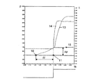
図3は、図2に示されるキャビティ9に備えられたセンサによる測定データの経時変化を示すグラフである。この図において、横軸は時間tsを秒単位で示し、左縦軸は圧力P、右縦軸は温度T(概念的)、曲線13は金型内の圧力の経時変化、曲線14は金型壁の温度の経時変化を示している。矢印15で示す曲線13と曲線14の交点は、温度が上昇する時点の圧力値を示す。すなわち、圧力差ΔPに基づいてせん断応力が自動的に算出される。せん断速度は、時間差Δtに基づいて算出される。
FIG. 3 is a graph showing the change over time of measurement data by the sensor provided in the
図4に示す第二の実施例のキャビティ17では、溶融物の流入口(ゲート19)から距離S(17)の位置に温度センサ18のみが備えられている。
In the
射出成形機を監視、データの記録及び/又は制御するため、金型のキャビティ内の溶融物の粘性の算出は次のように行なわれる。 In order to monitor, record and / or control the injection molding machine, the viscosity of the melt in the mold cavity is calculated as follows.
図2の第一の実施例では、射出成形機Pのノズル2を介してキャビティ9に溶融物を注入している間に、キャビティ9内の圧力差及び寸法(H×W×全体の長さ)に基づいて算定されたせん断応力とせん断速度の商から溶融物の粘性が決定される。図2の実施例では、溶融物の流入口に近い圧力センサ10が、圧力を測定する。溶融物が温度センサ11に到達時点でも圧力を測定し、図3の温度上昇が際立った時点の圧力値に相当する圧力差を算定する。この温度上昇点の圧力値と大気圧(1バール)との差を用いるので、第2の圧力値は必要ではない。この方法の利点は、温度センサ11が保圧工程への自動切換えにも使用できることである。それ以外に、温度センサ11を、溶融物の流れの何処かに設置してもよい。このことは、図2aに明瞭に示されている。図2aには、圧力センサ10及び温度センサ11の3つの実施例のそれぞれの配置が示されている。また図2aには、センサ配置に対応して図3と似たグラフが併せて示されている。圧力センサ10又は温度センサ11の配置位置に関係なく、溶融物が温度センサ11に到達するとせん断応力ΔP及びせん断速度Δtが算出され、それに基づいて粘性値が算出される。この値を予め設定した値か又はその近辺に保てば、射出成形方法を変更する必要はない。しかし、この値を変更して、所望の粘性値が得られるように、溶融物の温度及び/又は圧力などのパラメータを変更してもよい。
In the first embodiment of FIG. 2, the pressure difference and dimensions (H × W × total length in the cavity 9) while the melt is being injected into the
第一の実施例と較べて、図4に示す第二の実施例は、単に温度センサ18のみが溶融物の流路の途中に配置された単純化された例である。射出成形機Pのホットランナー系及び/又はノズル6における圧力差及び/又は油圧系の圧力差を用いて、せん断応力が算定される。金型のゲート19から金型壁の温度センサ18までの距離S(17)に基づいて、せん断速度が算定される。
Compared to the first embodiment, the second embodiment shown in FIG. 4 is a simplified example in which only the
ホットランナー及びノズル内の溶融物の圧力はそのまま真の圧力とし、油圧ピストン及び押出機の圧力の場合には、真の圧力に換算する必要がある。しかし、成形機を制御するために常に油圧が測定されており、ノズル又はホットランナーにおける溶融物の圧力測定とは異なってセンサを取付ける必要が無いので、油圧からの算定は低コストの方法である。しかし、この方法は摩擦損失並びに不正確さの基となる。 The pressure of the melt in the hot runner and the nozzle is set to the true pressure as it is, and in the case of the pressure of the hydraulic piston and the extruder, it is necessary to convert to the true pressure. However, since the oil pressure is always measured to control the molding machine and there is no need to install a sensor unlike the melt pressure measurement in the nozzle or hot runner, the calculation from the oil pressure is a low cost method. . However, this method is the basis for friction loss as well as inaccuracy.
せん断応力及びせん断速度から粘性の推移が得られる。 Transition of viscosity can be obtained from shear stress and shear rate.
特に第一の実施例が実用的であることが実証された。これに関連して、粘性は上述のように算定されて周知の方法により監視されると同時に、算定された粘性の推移が記録され且つ制御される。 In particular, the first example proved to be practical. In this connection, the viscosity is calculated as described above and monitored by known methods, while the calculated viscosity transition is recorded and controlled.
基本的には、粘性が異なると部品の特性が異なってくるので好ましくない。操業条件が異なるか又は原料の特性が異なる(装入の振れ)と、粘性が異なってくる。そのため、材料の受入れ検査に、本発明による方法及び装置を用いることも可能である。 Basically, if the viscosity is different, the characteristics of the parts will be different. Viscosities differ when operating conditions are different or raw material properties are different (charging swing). Therefore, it is also possible to use the method and apparatus according to the present invention for material acceptance inspection.
1 射出成形金型
1.1 キャビティ
2 ノズル
3 押出機
4 ホッパー
5 金型壁温度の測定位置
6 溶融物の圧力測定位置
7 油圧系の圧力測定位置
9 キャビティ
10 圧力センサ
11 温度センサ
12 金型壁
13 (金型内の)圧力経時変化曲線
14 (金型内の)温度経時変化曲線
15 (曲線13と曲線14の)交点を示す矢印
17 キャビティ
18 温度センサ
19 ゲート
20 キャビティ
21 圧力センサ
22 圧力センサ
P 射出成形機
H (キャビティの)高さ
W (キャビティの)幅
S 距離
DESCRIPTION OF
Claims (6)
金型(1)内の溶融物の粘性が圧力差(ΔP)、キャビティ(1.1;9;17;20)の形状及び溶融物の流れ速度に基づいたせん断応力とせん断速度の商により直接に算定され、
前記せん断応力に対しては溶融物が金型内圧力センサ(10)に到達した際の圧力と金型壁温度センサ(11)到達した際の圧力との圧力差(Δp)が用いられ、前記流れ速度に対しては溶融物が金型内圧センサ(10)から金型壁温度センサ(11)に到達するのに要する時間(Δt)が用いられることを特徴とする方法。A method of monitoring, recording and / or controlling data of an injection molding machine (P) having an injection mold (1) for injecting a melt,
Viscous pressure difference of the mold (1) melt in the ([Delta] P), the cavity by (1.1; 20 9; 17) the shape and the melt flow rate of shear stress and the quotient of the shear rate based on the Calculated directly ,
For the shear stress, the pressure difference (Δp) between the pressure when the melt reaches the pressure sensor (10) in the mold and the pressure when the mold wall temperature sensor (11) reaches is used, A method characterized in that the time (Δt) required for the melt to reach the mold wall temperature sensor (11) from the mold internal pressure sensor (10) is used for the flow velocity.
金型(1)内の溶融物の粘性が圧力差(ΔP)、キャビティ(1.1;9;17;20)の形状及び溶融物の流れ速度に基づいたせん断応力とせん断速度の商により直接に算定され、
前記粘性は、キャビティ(17)の溶融物の流路に備えられた少なくとも1つの金型壁温度センサ(18)に基づいて算定され、
せん断応力を決定するのに、溶融物を射出するのに必要なキャビティ内に備えられた機構により測定された動力より間接的に得られる射出成形機(P)の油圧系(7)及び/又はノズル(6)及び/又はホットランナーにおける溶融物の注入開始時点の圧力と、溶融物が金型壁温度センサ(18)に到達した時点の圧力との圧力差(Δp)が用いられ、
せん断速度を決定するのにキャビティ(17)の溶融物の流入口(ゲート19)から金型壁温度センサ(18)の位置まで距離又は所要時間が用いられることを特徴とする方法。A method of monitoring, recording and / or controlling data of an injection molding machine (P) having an injection mold (1) for injecting a melt,
Viscous pressure difference of the mold (1) melt in the ([Delta] P), the cavity by (1.1; 20 9; 17) the shape and the melt flow rate of shear stress and the quotient of the shear rate based on the Calculated directly,
The viscosity is calculated based on at least one mold wall temperature sensor (18) provided in the melt flow path of the cavity (17);
To determine the shear stress, the hydraulic system (7) of the injection molding machine (P) obtained indirectly from the power measured by the mechanism provided in the cavity necessary to inject the melt and / or The pressure difference (Δp) between the pressure at the start of pouring the melt in the nozzle (6) and / or the hot runner and the pressure at the time when the melt reaches the mold wall temperature sensor (18 ) is used,
Wherein the distance or time required to position the inlet of the melt cavity (17) to determine the shear speed mold wall temperature sensor from (gate 19) (18) is used.
少なくとも1つの金型内圧力センサ(10、21、22)及び金型壁温度センサ(11、18)が備えられ、
溶融物をキャビティ(1.1、9、17、20)に注入する間に測定される圧力差及びキャビティ(1.1、9、17、20)の形状により算定されるせん断応力とせん断速度の商から前記粘性が算定されることを特徴とする装置。An apparatus for performing the method of claim 1, comprising:
At least one in-mold pressure sensor (10, 21, 22) and a mold wall temperature sensor (11, 18),
Of the stress and shear rate calculated by the pressure difference measured during the injection of the melt into the cavity (1.1, 9, 17, 20) and the shape of the cavity (1.1, 9, 17, 20). An apparatus characterized in that the viscosity is calculated from a quotient.
溶融物の流入口(ゲート19)から所定の距離(S17)のキャビティの壁に金型壁温度センサ(18)が備えられ、
射出成形機(P)の注入ノズル(6)及び/又は油圧系(7)及び/又はホットランナーに圧力センサが備えられていることを特徴とする装置。An apparatus for performing the method of claim 2, comprising:
A mold wall temperature sensor (18) is provided on the cavity wall at a predetermined distance (S17) from the melt inlet (gate 19),
An apparatus comprising a pressure sensor in an injection nozzle (6) and / or a hydraulic system (7) and / or a hot runner of an injection molding machine (P).
Applications Claiming Priority (3)
| Application Number | Priority Date | Filing Date | Title |
|---|---|---|---|
| DE102007045111 | 2007-09-20 | ||
| DE102007045111.5 | 2007-09-20 | ||
| PCT/EP2008/007978 WO2009040077A1 (en) | 2007-09-20 | 2008-09-22 | Method and device for monitoring, documenting, and/or controlling an injection molding machine |
Publications (3)
| Publication Number | Publication Date |
|---|---|
| JP2010538877A JP2010538877A (en) | 2010-12-16 |
| JP2010538877A5 JP2010538877A5 (en) | 2011-03-10 |
| JP5153877B2 true JP5153877B2 (en) | 2013-02-27 |
Family
ID=40227488
Family Applications (1)
| Application Number | Title | Priority Date | Filing Date |
|---|---|---|---|
| JP2010525268A Expired - Fee Related JP5153877B2 (en) | 2007-09-20 | 2008-09-22 | Injection molding machine monitoring, data recording and / or control method and apparatus |
Country Status (9)
| Country | Link |
|---|---|
| US (1) | US8329075B2 (en) |
| EP (1) | EP2212086B2 (en) |
| JP (1) | JP5153877B2 (en) |
| KR (1) | KR101529973B1 (en) |
| DK (1) | DK2212086T4 (en) |
| ES (1) | ES2531091T3 (en) |
| HU (1) | HUE024564T2 (en) |
| PL (1) | PL2212086T3 (en) |
| WO (1) | WO2009040077A1 (en) |
Cited By (1)
| Publication number | Priority date | Publication date | Assignee | Title |
|---|---|---|---|---|
| US8567118B2 (en) | 2006-02-14 | 2013-10-29 | Sarah E. Farmer | Belowground tree anchoring apparatus and method |
Families Citing this family (18)
| Publication number | Priority date | Publication date | Assignee | Title |
|---|---|---|---|---|
| KR20120096484A (en) * | 2009-10-05 | 2012-08-30 | 프리아무스 시스템 테크놀로지스 아게 | Method for controlling the production of a product |
| DE102010027942A1 (en) * | 2010-04-20 | 2011-10-20 | Robert Bosch Gmbh | Measuring device and measuring method for an injection molding machine for determining a batch-specific characteristic number |
| CN103415383A (en) | 2011-01-17 | 2013-11-27 | 普里阿摩斯系统科技股份公司 | Method for producing multilayer objects |
| DE102011054278B4 (en) | 2011-10-07 | 2018-07-05 | Priamus System Technologies Ag | Method for producing multilayer articles |
| DE102011000178A1 (en) | 2011-01-17 | 2012-07-19 | Priamus System Technologies Ag | Method for manufacturing multilayer articles made of plastic melt, involves determining viscosity of polymer melt in injection molding tool by preforming melt with barrier layer |
| US8715547B2 (en) | 2011-02-24 | 2014-05-06 | Mold-Masters (2007) Limited | Closed loop control of auxiliary injection unit |
| US9097565B2 (en) | 2012-03-30 | 2015-08-04 | Beaumont Technologies, Inc. | Method and apparatus for material flow characterization |
| PT106938A (en) * | 2013-05-10 | 2014-11-10 | Famolde Fabricaç O E Com Izaç O De Moldes S A | DEVICE FOR OPTIMIZATION AND PRODUCTION CONTROL OF THE THERMOPLASTIC INJECTION PROCESS AND THEIR METHOD |
| BR112016002259A2 (en) | 2013-08-01 | 2017-08-29 | Imflux Inc | INJECTION MOLDING MACHINES AND METHODS FOR MAKING CHANGES TO MATERIAL PROPERTIES DURING INJECTION MOLDING OPERATIONS |
| KR20160027114A (en) | 2013-08-01 | 2016-03-09 | 임플럭스 인코포레이티드 | Injection molding machines and methods for accounting for changes in material properties during injection molding runs |
| US8980146B2 (en) | 2013-08-01 | 2015-03-17 | Imflux, Inc. | Injection molding machines and methods for accounting for changes in material properties during injection molding runs |
| JP6202097B2 (en) * | 2013-08-09 | 2017-09-27 | 日産自動車株式会社 | Injection control method and injection control device |
| JP5806374B2 (en) * | 2014-08-29 | 2015-11-10 | 東洋機械金属株式会社 | Automatic operation method of injection molding machine |
| JP2021528286A (en) * | 2018-06-21 | 2021-10-21 | クレックナー デスマ エラストマーテヒニク ゲーエムベーハーKloeckner Desma Elastomertechnik GmbH | Online detection method of rheology of thermoplastic and / or elastomeric materials for the manufacture of injection molded parts |
| CN113715284B (en) * | 2021-08-31 | 2022-11-08 | 中南大学 | Polymer viscosity on-line detection system and method for micro-scale rectangular slit |
| WO2023114049A1 (en) | 2021-12-13 | 2023-06-22 | Barnes Group Inc. | Injection molding device and method |
| WO2023244723A1 (en) * | 2022-06-15 | 2023-12-21 | iMFLUX Inc. | Systems and approaches for manufacturing parts |
| DE102022117755A1 (en) | 2022-07-15 | 2024-01-18 | Priamus System Technologies, Zweigniederlassung der Barnes Group Suisse Industries GmbH | Sensor unit for monitoring a cavity in an injection mold |
Family Cites Families (19)
| Publication number | Priority date | Publication date | Assignee | Title |
|---|---|---|---|---|
| US3438158A (en) | 1967-08-21 | 1969-04-15 | Daniel F Kane | Car pod |
| AT333024B (en) * | 1972-12-05 | 1976-10-25 | Fur Verbrennungsmotoren Prof D | DIGITAL CONTROL ARRANGEMENT FOR A PRESSURE-OPERATED WORK CYLINDER OF A SCREW INJECTION MOLDING MACHINE |
| JPS5156868A (en) † | 1974-11-13 | 1976-05-18 | Kobe Steel Ltd | SHASHUTSUSE IKEIKI |
| JPS6246615A (en) * | 1985-08-26 | 1987-02-28 | Matsushita Electric Ind Co Ltd | Injection molding and device thereof |
| JPS62144916A (en) * | 1985-12-19 | 1987-06-29 | Matsushita Electric Ind Co Ltd | Monitoring process for resin molding and its device |
| JPS633927A (en) † | 1986-06-24 | 1988-01-08 | Mitsubishi Heavy Ind Ltd | Method and device for controlling injection of injection molder |
| JPH05329864A (en) * | 1992-05-29 | 1993-12-14 | Mitsubishi Heavy Ind Ltd | On-line resin viscosity measuring method and quality discriminating method of molded product |
| US5221500A (en) * | 1992-07-10 | 1993-06-22 | The Goodyear Tire & Rubber Company | Mechanical in situ curometer |
| JPH06320587A (en) * | 1993-05-14 | 1994-11-22 | Olympus Optical Co Ltd | Injection molding machine |
| JP3310071B2 (en) † | 1993-10-28 | 2002-07-29 | 松下電器産業株式会社 | Control method of injection molding machine |
| FR2750918B1 (en) * | 1996-07-09 | 1999-04-09 | Transvalor Sa | CONTROL AND REGULATION OF AN INJECTION MOLDING PRESS |
| SE507950C2 (en) † | 1996-11-04 | 1998-08-03 | Perstorp Ab | Procedure for injection molding of products with hollow profiles |
| JP3842868B2 (en) | 1997-05-26 | 2006-11-08 | 松下電工株式会社 | Injection molding method and apparatus |
| JPH1110693A (en) * | 1997-06-20 | 1999-01-19 | Matsushita Electric Works Ltd | Injection molding method and device for the same |
| CA2427832C (en) * | 2000-11-06 | 2008-01-08 | Frederick J. Buja | Method and apparatus for controlling a mold melt-flow process using temperature sensors |
| DE50202221C5 (en) † | 2001-04-05 | 2018-12-27 | Priamus System Technologies Ag | METHOD FOR FILLING THE CAVITY OF A TOOL |
| TWI221325B (en) * | 2003-10-24 | 2004-09-21 | Advanced Semiconductor Eng | Molding apparatus with a pressure sensor for semiconductor package |
| JP4361459B2 (en) † | 2004-10-15 | 2009-11-11 | 三菱重工プラスチックテクノロジー株式会社 | Injection molding method and mold temperature control device for injection molding machine |
| DE102005032367A1 (en) | 2005-07-08 | 2007-01-11 | Priamus System Technologies Ag | Method for monitoring and / or regulating the melt filling of at least one cavity |
-
2008
- 2008-09-22 ES ES08802473T patent/ES2531091T3/en active Active
- 2008-09-22 KR KR1020107007910A patent/KR101529973B1/en active IP Right Grant
- 2008-09-22 US US12/679,036 patent/US8329075B2/en active Active
- 2008-09-22 HU HUE08802473A patent/HUE024564T2/en unknown
- 2008-09-22 WO PCT/EP2008/007978 patent/WO2009040077A1/en active Application Filing
- 2008-09-22 EP EP08802473.2A patent/EP2212086B2/en active Active
- 2008-09-22 PL PL08802473T patent/PL2212086T3/en unknown
- 2008-09-22 DK DK08802473.2T patent/DK2212086T4/en active
- 2008-09-22 JP JP2010525268A patent/JP5153877B2/en not_active Expired - Fee Related
Cited By (1)
| Publication number | Priority date | Publication date | Assignee | Title |
|---|---|---|---|---|
| US8567118B2 (en) | 2006-02-14 | 2013-10-29 | Sarah E. Farmer | Belowground tree anchoring apparatus and method |
Also Published As
| Publication number | Publication date |
|---|---|
| PL2212086T3 (en) | 2015-04-30 |
| KR20100083144A (en) | 2010-07-21 |
| US20100252944A1 (en) | 2010-10-07 |
| DK2212086T3 (en) | 2015-02-16 |
| DK2212086T4 (en) | 2023-06-06 |
| JP2010538877A (en) | 2010-12-16 |
| US8329075B2 (en) | 2012-12-11 |
| WO2009040077A1 (en) | 2009-04-02 |
| EP2212086B1 (en) | 2014-12-17 |
| EP2212086A1 (en) | 2010-08-04 |
| EP2212086B2 (en) | 2023-03-15 |
| KR101529973B1 (en) | 2015-06-18 |
| ES2531091T3 (en) | 2015-03-10 |
| HUE024564T2 (en) | 2016-02-29 |
Similar Documents
| Publication | Publication Date | Title |
|---|---|---|
| JP5153877B2 (en) | Injection molding machine monitoring, data recording and / or control method and apparatus | |
| US9097565B2 (en) | Method and apparatus for material flow characterization | |
| CN111163914B (en) | Real-time material and speed control in a molding system | |
| Chien et al. | Study on rheological behavior of polymer melt flowing through micro-channels considering the wall-slip effect | |
| Chen et al. | Rheological behavior of POM polymer melt flowing through micro-channels | |
| CN101532939B (en) | Device and method for measuring steady-state extrusion viscous dissipation of micro-scale polymer fused mass | |
| JP2010538877A5 (en) | ||
| US20110254183A1 (en) | Measuring device and measuring method for an injection molding machine for ascertaining a batch-specific characteristic number | |
| JP6972742B2 (en) | Viscosity measurement method and equipment for unvulcanized rubber and flow simulation method for unvulcanized rubber | |
| Friesenbichler et al. | Measuring the pressure dependent viscosity at high shear rates using a new rheological injection mould | |
| KR101336156B1 (en) | An apparatus for viscosity measurement with a mold module and a method therefor | |
| Nguyen‐Chung et al. | Determination of the heat transfer coefficient from short‐shots studies and precise simulation of microinjection molding | |
| WO2021141928A1 (en) | Melt pressure control of injection molding | |
| TW202234186A (en) | Injection molding machine and inspection method of injection molding machine | |
| Wu et al. | In-line steady shear flow characteristics of polymer melt in rectangular slit cavities during thin-wall/micro injection molding | |
| Friesenbichler et al. | Rheometry of polymer melts using processing machines | |
| JP2021133632A (en) | Injection device and injection control method | |
| US20210339448A1 (en) | Method for Predicting a Polymer's Pressure, Flow Rate, and Temperature Relationship While Flowing within an Injection Mold | |
| JPH0124253B2 (en) | ||
| CN113878830A (en) | Device and method for detecting rheology of micro-injection molding polymer on line under ultrasonic energy field | |
| CN1663773A (en) | Method and apparatus for detecting polymer dynamic injection rheological properties and behaviors | |
| JPH0322287B2 (en) | ||
| JP7274348B2 (en) | Method for measuring fluidity index of molten resin | |
| TWI657911B (en) | Method of monitoring molding quality | |
| JP6939211B2 (en) | Rubber product manufacturing method and equipment |
Legal Events
| Date | Code | Title | Description |
|---|---|---|---|
| A521 | Request for written amendment filed |
Free format text: JAPANESE INTERMEDIATE CODE: A523 Effective date: 20110119 |
|
| A621 | Written request for application examination |
Free format text: JAPANESE INTERMEDIATE CODE: A621 Effective date: 20110119 |
|
| A977 | Report on retrieval |
Free format text: JAPANESE INTERMEDIATE CODE: A971007 Effective date: 20120706 |
|
| A131 | Notification of reasons for refusal |
Free format text: JAPANESE INTERMEDIATE CODE: A131 Effective date: 20120717 |
|
| A521 | Request for written amendment filed |
Free format text: JAPANESE INTERMEDIATE CODE: A523 Effective date: 20121009 |
|
| TRDD | Decision of grant or rejection written | ||
| A01 | Written decision to grant a patent or to grant a registration (utility model) |
Free format text: JAPANESE INTERMEDIATE CODE: A01 Effective date: 20121106 |
|
| A61 | First payment of annual fees (during grant procedure) |
Free format text: JAPANESE INTERMEDIATE CODE: A61 Effective date: 20121204 |
|
| FPAY | Renewal fee payment (event date is renewal date of database) |
Free format text: PAYMENT UNTIL: 20151214 Year of fee payment: 3 |
|
| R150 | Certificate of patent or registration of utility model |
Ref document number: 5153877 Country of ref document: JP Free format text: JAPANESE INTERMEDIATE CODE: R150 Free format text: JAPANESE INTERMEDIATE CODE: R150 |
|
| R250 | Receipt of annual fees |
Free format text: JAPANESE INTERMEDIATE CODE: R250 |
|
| R250 | Receipt of annual fees |
Free format text: JAPANESE INTERMEDIATE CODE: R250 |
|
| R250 | Receipt of annual fees |
Free format text: JAPANESE INTERMEDIATE CODE: R250 |
|
| R250 | Receipt of annual fees |
Free format text: JAPANESE INTERMEDIATE CODE: R250 |
|
| R250 | Receipt of annual fees |
Free format text: JAPANESE INTERMEDIATE CODE: R250 |
|
| R250 | Receipt of annual fees |
Free format text: JAPANESE INTERMEDIATE CODE: R250 |
|
| LAPS | Cancellation because of no payment of annual fees |