JP5153349B2 - 3-way ball valve - Google Patents
3-way ball valve Download PDFInfo
- Publication number
- JP5153349B2 JP5153349B2 JP2008004279A JP2008004279A JP5153349B2 JP 5153349 B2 JP5153349 B2 JP 5153349B2 JP 2008004279 A JP2008004279 A JP 2008004279A JP 2008004279 A JP2008004279 A JP 2008004279A JP 5153349 B2 JP5153349 B2 JP 5153349B2
- Authority
- JP
- Japan
- Prior art keywords
- valve
- valve body
- opening
- port
- ports
- Prior art date
- Legal status (The legal status is an assumption and is not a legal conclusion. Google has not performed a legal analysis and makes no representation as to the accuracy of the status listed.)
- Active
Links
Images


Classifications
-
- F—MECHANICAL ENGINEERING; LIGHTING; HEATING; WEAPONS; BLASTING
- F16—ENGINEERING ELEMENTS AND UNITS; GENERAL MEASURES FOR PRODUCING AND MAINTAINING EFFECTIVE FUNCTIONING OF MACHINES OR INSTALLATIONS; THERMAL INSULATION IN GENERAL
- F16K—VALVES; TAPS; COCKS; ACTUATING-FLOATS; DEVICES FOR VENTING OR AERATING
- F16K5/00—Plug valves; Taps or cocks comprising only cut-off apparatus having at least one of the sealing faces shaped as a more or less complete surface of a solid of revolution, the opening and closing movement being predominantly rotary
- F16K5/06—Plug valves; Taps or cocks comprising only cut-off apparatus having at least one of the sealing faces shaped as a more or less complete surface of a solid of revolution, the opening and closing movement being predominantly rotary with plugs having spherical surfaces; Packings therefor
- F16K5/0605—Plug valves; Taps or cocks comprising only cut-off apparatus having at least one of the sealing faces shaped as a more or less complete surface of a solid of revolution, the opening and closing movement being predominantly rotary with plugs having spherical surfaces; Packings therefor with particular plug arrangements, e.g. particular shape or built-in means
-
- F—MECHANICAL ENGINEERING; LIGHTING; HEATING; WEAPONS; BLASTING
- F16—ENGINEERING ELEMENTS AND UNITS; GENERAL MEASURES FOR PRODUCING AND MAINTAINING EFFECTIVE FUNCTIONING OF MACHINES OR INSTALLATIONS; THERMAL INSULATION IN GENERAL
- F16K—VALVES; TAPS; COCKS; ACTUATING-FLOATS; DEVICES FOR VENTING OR AERATING
- F16K11/00—Multiple-way valves, e.g. mixing valves; Pipe fittings incorporating such valves
- F16K11/02—Multiple-way valves, e.g. mixing valves; Pipe fittings incorporating such valves with all movable sealing faces moving as one unit
- F16K11/08—Multiple-way valves, e.g. mixing valves; Pipe fittings incorporating such valves with all movable sealing faces moving as one unit comprising only taps or cocks
- F16K11/087—Multiple-way valves, e.g. mixing valves; Pipe fittings incorporating such valves with all movable sealing faces moving as one unit comprising only taps or cocks with spherical plug
-
- F—MECHANICAL ENGINEERING; LIGHTING; HEATING; WEAPONS; BLASTING
- F16—ENGINEERING ELEMENTS AND UNITS; GENERAL MEASURES FOR PRODUCING AND MAINTAINING EFFECTIVE FUNCTIONING OF MACHINES OR INSTALLATIONS; THERMAL INSULATION IN GENERAL
- F16K—VALVES; TAPS; COCKS; ACTUATING-FLOATS; DEVICES FOR VENTING OR AERATING
- F16K27/00—Construction of housing; Use of materials therefor
- F16K27/06—Construction of housing; Use of materials therefor of taps or cocks
- F16K27/067—Construction of housing; Use of materials therefor of taps or cocks with spherical plugs
-
- F—MECHANICAL ENGINEERING; LIGHTING; HEATING; WEAPONS; BLASTING
- F16—ENGINEERING ELEMENTS AND UNITS; GENERAL MEASURES FOR PRODUCING AND MAINTAINING EFFECTIVE FUNCTIONING OF MACHINES OR INSTALLATIONS; THERMAL INSULATION IN GENERAL
- F16K—VALVES; TAPS; COCKS; ACTUATING-FLOATS; DEVICES FOR VENTING OR AERATING
- F16K31/00—Actuating devices; Operating means; Releasing devices
- F16K31/44—Mechanical actuating means
- F16K31/60—Handles
-
- F—MECHANICAL ENGINEERING; LIGHTING; HEATING; WEAPONS; BLASTING
- F16—ENGINEERING ELEMENTS AND UNITS; GENERAL MEASURES FOR PRODUCING AND MAINTAINING EFFECTIVE FUNCTIONING OF MACHINES OR INSTALLATIONS; THERMAL INSULATION IN GENERAL
- F16K—VALVES; TAPS; COCKS; ACTUATING-FLOATS; DEVICES FOR VENTING OR AERATING
- F16K5/00—Plug valves; Taps or cocks comprising only cut-off apparatus having at least one of the sealing faces shaped as a more or less complete surface of a solid of revolution, the opening and closing movement being predominantly rotary
- F16K5/06—Plug valves; Taps or cocks comprising only cut-off apparatus having at least one of the sealing faces shaped as a more or less complete surface of a solid of revolution, the opening and closing movement being predominantly rotary with plugs having spherical surfaces; Packings therefor
- F16K5/0663—Packings
- F16K5/0689—Packings between housing and plug
Description
本発明は、ビルの空調設備等に用いられる三方ボール弁に関する。 The present invention relates to a three-way ball valve used for air conditioning equipment in a building.
従来、三方ボール弁は、例えばビルの空調設備における湯水混合または分流等に使用されている(例えば、特許文献1参照)。 Conventionally, a three-way ball valve is used for hot water mixing or branching in an air conditioning facility of a building, for example (see, for example, Patent Document 1).
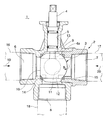
前記特許文献1に記載されている三方ボール弁1は、図8に示すように、弁本体2内に回動自在に組み込まれたボール状の弁体3と、この弁体3を回動させる弁軸4とを備えている。
As shown in FIG. 8, the three-
前記弁本体2は、前記弁軸4が挿入される弁軸用孔5と、前記弁軸4の軸線の延長線と直交する方向において対向する第1、第2の開口6、7と、前記弁軸4の軸線方向において開口する第3の開口8とを有し、内部中央に弁体3を収納する弁室9が形成されている。
The
前記弁体3には、外周面に開口する第1、第2、第3のポート10、11、12および嵌合部13を有している。第1、第2のポート10、11は、弁体3の外周面で弁軸4の軸線の延長線と直交する方向において回転方向に90°離間して形成されている。第3のポート12は、前記弁軸4の軸線方向で弁体3の下面中央に形成されている。嵌合部13は弁体3の上面中央に形成され、前記弁軸4の内端4aが嵌合している。なお、14、15は、弁体3と弁室9との隙間をシールする第1、第2のシートリング、16、17、18は第1、第2、第3の開口6、7、8にそれぞれ接続された配管を示す。
The
このような弁体3を備えた三方ボール弁1は、弁軸4によって弁体3を90°の角度範囲内で往復回動させることにより弁体3によって独立した2つの流路を形成することができる。すなわち、弁体3を回動させて図8に示す状態にすると、第1のポート10が第1の開口6に対して全開状態になり、第2のポート11が第2の開口7に対して全閉状態に切り替わる。この状態において、第1のポート10と第3のポート12とを介して配管16と配管18を接続する流路が形成される。一方、配管17および18は弁体3によって遮断される。したがって、配管16内の流体(例えば、水)19は、第1のポート10および第3のポート12を通って第3の開口8から流出し配管18に流れる。次に、図8に示す状態から弁体3を矢印B方向に90°回動させて第1のポート10を第1の開口6に対して全閉状態にし、第2のポート11を第2の開口7に対して全開状態に切り替えると、第2のポート11と第3のポート12を介して配管17と配管18を接続する流路が形成される。一方、配管16および18は弁体3によって遮断される。したがって、配管17内の流体(例えば、温水)20は、第2のポート11および第3のポート12を通って第3の開口8から流出し配管18に流れる。また、図8に示す状態から弁体3を矢印B方向に90°以内の角度範囲内で所要角度回動させて第1、第2のポート10、11を第1、第2の開口6、7に対して中間開度にすると、第1、第2のポート10、11が第1、第2の開口6、7に対してそれぞれ半開状態になり、第1、第2、第3のポート10、11、12を介して配管16、17と配管18を接続する流路が形成される。このため、配管16、17内の流体19、20は第1、第2のポート10、11から弁体3内に流入すると混合され、第3のポート12を通って配管18に流れる。
The three-
しかしながら、このような従来の三方ボール弁1においては、弁体3の回転角度が中間開度になると、構造上第1のポート10から流入した流体19と、第2のポート11から流入した流体20が弁体3内で衝突することにより第3のポート12から流出する流体19、20の流量(Cv値)が減少するために、差圧が大きくなり、騒音や配管の振動等が起こり易いという問題があった。
However, in such a conventional three-
そこで、このような問題を解決するために上記した特許文献1に記載された発明に係る三方ボール弁は、弁体内の通路に張り出す張出部を弁軸4の軸線の延長線上に形成することにより、第1、第2のポート10、11から流入する流体19、20の衝突を回避し、弁のCv値を改善するようにしている。
Accordingly, in order to solve such a problem, the three-way ball valve according to the invention described in
上記したように、弁体の内部に張出部を突設した三方ボール弁においては、中間開度におけるCv値を改善することができる。しかしながら、低開度時または高開度時、すなわち、第1のポート10または第2のポート11からのみ流体19または20が弁本体2内に流入する開度時においては、張出部が流体19または20の阻害要因になり、第3のポートに流出する流体の流量が減少し、弁としての流量特性を低下させるという問題があった。
As described above, in the three-way ball valve in which the projecting portion protrudes inside the valve body, the Cv value at the intermediate opening can be improved. However, at the time of low opening or high opening, that is, at the opening at which the
本発明は、上記した従来の問題を解決するためになされたもので、その目的とするところは、低開度時や高開度時のCv値を減少させることなく中間開度時のCv値を改善することができるようにした三方ボール弁を提供することにある。 The present invention has been made to solve the above-described conventional problems, and its object is to reduce the Cv value at the intermediate opening without decreasing the Cv value at the low opening or the high opening. It is an object of the present invention to provide a three-way ball valve that can improve the above-mentioned characteristics.
本発明は上記目的を達成するために、弁軸が挿入される弁軸用孔と、前記弁軸の軸線方向と直交する方向において対向する第1、第2の開口と、前記弁軸の軸線方向に開口する第3の開口とを有し、内部に弁室が形成された弁本体と、前記弁軸が嵌合する嵌合部と、前記弁軸の軸線方向と直交する方向において回転方向に90°離間して形成された第1、第2のポートと、前記第3の開口に対応して前記弁軸の軸線方向に形成された第3のポートとを有し、前記弁室内に第1、第2のシートリングを介して回動自在に配設されたボール状の弁体とを備え、前記弁体の前記第1及び第2のポートと対向することがない前記弁室の内壁と、前記弁体の前記第1及び第2のポートが形成されていない外周面と、前記第1、第2のシートリングとの間には前記弁体の第1及び第2のポートを経由せずに前記第3の開口に連通する連通路が形成され、前記連通路を形成する前記弁体の外周面に、前記第1、第2のポートが中間開度のときのみに前記第1、第2の開口から弁本体内に流入する流体の一部を前記連通路を経由して前記第3の開口に導く第1、第2のバイパス通路をそれぞれ形成し、前記第1のバイパス通路の通路断面積は、第1のポートの開度が0%において零で、0%から50%の範囲内では徐々に増加し、開度が50%を超えると徐々に減少して100%において零になり、前記第2のバイパス通路の通路断面積は、第2のポートの開度が0%において零で、0%から50%の範囲内では徐々に増加し、開度が50%を超えると徐々に減少して100%において零になり、前記第1、第2のバイパス通路のいずれか一方は、弁体の外周面に対向して配設された一対の凹部からなり、これらの凹部間には表面が弁本体の外周面と同一の曲率からなる平面視弧状の残余部が設けられているものである。 To achieve the above object, the present invention provides a valve shaft hole into which a valve shaft is inserted, first and second openings facing each other in a direction orthogonal to the axial direction of the valve shaft, and the axis of the valve shaft. A valve body having a valve chamber formed therein, a fitting portion into which the valve shaft is fitted, and a rotation direction in a direction orthogonal to the axial direction of the valve shaft And a third port formed in the axial direction of the valve shaft so as to correspond to the third opening, and is provided in the valve chamber. A ball-shaped valve body rotatably disposed via first and second seat rings, the valve chamber not facing the first and second ports of the valve body Between the inner wall, the outer peripheral surface of the valve body where the first and second ports are not formed, and the first and second seat rings Is formed with a communication path communicating with the third opening without passing through the first and second ports of the valve body, and the first, second, Only when the second port has an intermediate opening degree, the first and second fluids that lead part of the fluid flowing into the valve body from the first and second openings to the third opening via the communication passage. The first cross-sectional area of the first bypass passage is zero when the opening degree of the first port is 0%, and gradually increases within the range of 0% to 50%. Gradually decreases to 100% when the value exceeds 50%, and the cross-sectional area of the second bypass passage is zero when the opening degree of the second port is 0%, from 0% to 50%. It gradually increases within the range, gradually decreases when the opening exceeds 50%, and becomes zero at 100%. One of the first and second bypass passages is composed of a pair of recesses disposed opposite the outer peripheral surface of the valve body, and the surface has the same curvature as the outer peripheral surface of the valve body between these recesses. The residual part of arc view shape which consists of is provided .
本発明においては、弁の中間開度のとき、弁体内では第1、第2のポートから流入した流体が互いに衝突するため、第3のポートを経て第3の開口に流出する流量は減少する。一方、弁体の外周面に形成した第1、第2のバイパス通路に流入する流体は連通路を経て第3の開口に流出するため、第3の開口を通過する流体の総流量が増加し、中間開度時における弁のCv値が改善される。 In the present invention, when the valve is at an intermediate opening, the fluids flowing in from the first and second ports collide with each other in the valve body, so the flow rate flowing out to the third opening through the third port decreases. . On the other hand, since the fluid flowing into the first and second bypass passages formed on the outer peripheral surface of the valve body flows out to the third opening through the communication passage, the total flow rate of the fluid passing through the third opening increases. The Cv value of the valve at the intermediate opening is improved.
また、第1のバイパス通路の通路断面積は、第1のポートの開度が0%において零で、0%から50%の範囲内では徐々に増加し、開度が50%を超えると徐々に減少して100%において零になり、同じく第2のバイパス通路の通路断面積は、第2のポートの開度が0%において零で、0%から50%の範囲内では徐々に増加し、開度が50%を超えると徐々に減少して100%において零になるので、全開時のCv値が増加したり減少したりすることがなく、また第1、第2のポートの全閉時の締め切り性を良好に確保することができる。 The passage cross-sectional area of the first bypass passage is zero when the opening degree of the first port is 0%, gradually increases within the range of 0% to 50%, and gradually when the opening degree exceeds 50%. The cross sectional area of the second bypass passage is zero when the opening degree of the second port is 0% and gradually increases within the range of 0% to 50%. When the opening degree exceeds 50%, it gradually decreases and becomes zero at 100%, so that the Cv value at full opening does not increase or decrease, and the first and second ports are fully closed. The deadline at the time can be secured satisfactorily.
以下、本発明を図面に示す実施の形態に基づいて詳細に説明する。
図1は本発明に係る三方ボール弁の一実施の形態を示す断面図、図2は弁体の第1、第2のポート側から見た外観斜視図、図3は弁体の第1、第2のバイパス通路側から見た外観斜視図、図4は弁体を示す図で、(a)は弁体の中心を通る水平断面図、(b)は(a)図のA−A線断面図、(c)は(a)図のB−B線断面図、図5は図1のV−V線断面図で、(a)は第1のポートの弁開度が100%の状態を示す断面図、(b)は第1のポートの弁開度が50%の状態を示す断面図、(c)は第1のポートの弁開度が0%の状態を示す断面図である。
Hereinafter, the present invention will be described in detail based on embodiments shown in the drawings.
FIG. 1 is a sectional view showing an embodiment of a three-way ball valve according to the present invention, FIG. 2 is an external perspective view seen from the first and second port sides of the valve body, and FIG. FIG. 4 is a view showing the valve body, (a) is a horizontal sectional view passing through the center of the valve body, and (b) is a line AA in FIG. Sectional view, (c) is a sectional view taken along line BB in FIG. 5 (a), FIG. 5 is a sectional view taken along line VV in FIG. 1, and (a) is a state in which the valve opening degree of the first port is 100%. (B) is a cross-sectional view showing a state where the valve opening degree of the first port is 50%, (c) is a cross-sectional view showing a state where the valve opening degree of the first port is 0%. .
これらの図おいて、全体を符号30で示す三方ボール弁は、図8に示した従来の三方ボール弁1と、弁体31の構造が若干異なるだけで、その他の構造は同一である。すなわち、三方ボール弁30は、十字型の弁本体2と、この弁本体2の内部中央に水平方向(矢印A、B方向)に回動自在に収納された弁体31と、この弁体31を矢印A、B方向に略90°の角度範囲内で往復回動させる弁軸4等で構成されている。なお、図8と同一構成部品、部分については同一符号をもって示し、その説明を適宜省略する。
In these figures, the three-way ball valve indicated generally by the
前記弁本体2は、通常鋳物製の弁ケース34と管体35との二つの部材によって形成されている。弁ケース34は、上下および左右の4方向に開放する略横向きT字状(または十字状)に形成することにより、4つの孔、すなわち上方に開口し前記弁軸4が回動自在に貫通する弁軸用孔5と、前記弁軸4の軸線と直交する方向に開口し互いに対向する第1の開口6および接続孔38と、下方に開口する第3の開口8とを有している。弁ケース34の内部中央、すなわち弁軸用孔5の直下部分は、前記弁体31を回動自在に収納する弁室9を形成している。
The
前記管体35は直管からなり、上流側開口端部が前記弁ケース34の接続孔38にシール部材41を介して螺合され、下流側開口端部が第2の開口7を形成している。このため、弁ケース34の第1の開口6と管体35の第2の開口7は、弁軸4の軸線方向と直交する方向において対向している。弁本体2内への弁体31の組込みに際しては、管体35を弁ケース34から取外した状態で弁体31を第1、第2のシートリング14、15とともに組込む。そして、管体35を弁ケース34の接続口38にねじ込むことにより、第1、第2のシートリング14、15を弁体31の外周面に押し付け、これにより弁体31を回動可能に支持するとともに弁室9と弁体31との隙間をシールする。弁室9の内壁と、弁体31の外周面と第1、第2のシートリング14,15との間に形成された狭い隙間は、前記第3の開口8に連通する連通路39を形成している。
The
前記弁軸4は、弁本体2の弁軸用孔5にシール部材40を介して回動自在に挿入され、内端に突設した嵌合部4aが前記弁体31の嵌合部13に挿入固定されている。弁軸4の外端は、電動アクチュエータ(図示せず)に連結されるか、またはハンドルが取付けられ手動操作されるように構成されている。
The valve shaft 4 is rotatably inserted into the
前記弁体31は、中空のボール状(球状)に形成され、第1、第2、第3のポート10、11、12と、前記嵌合部13を有している。第1、第2のポート10、11は、弁軸4の軸線と直交し弁体31の回転中心Oを含む面内において弁体31の回転方向に90°離間して形成されている。第1、第2のポート10、11は、弁体31内に形成したL字状の通路43によって連通している。第3のポート12は、弁軸4の軸線方向で弁体31の下面中央に形成され、弁体31内において前記通路43に通路44を介して連通している。弁体31の上面中央には、前記弁軸4の嵌合部4aが嵌合する前記嵌合凹部13が形成されている。
The
また、弁体31の外周面には、第1のポート10の中間開度時(図5(b))に前記第1の開口6から弁本体2内に流入する流体19の一部を前記連通路39を経由して前記第3の開口8に導く第1のバイパス通路46が形成されている。この第1のバイパス通路46は、図3〜図5に示すように、第1のポート10の側方で第2のポート11とは反対側に90°回転した位置に形成されている。また、この第1のバイパス通路46は、弁体31の外周面で弁軸4の軸線と直交し回転中心Oを含む水平面を挟んでその上下に対向するように形成された2つの半円形の凹部46a、46bで構成されている。これらの凹部46a、46bは、弁体31の外周面の一部を垂直に切断除去することにより形成され、平面視弧状の残余部46cによって仕切られている。
Further, a part of the fluid 19 flowing into the
このような第1のバイパス通路46は、2つの凹部46a、46bが半円形に形成されていることから、第1のポート10の開度が0%から50%の範囲内においては徐々に増加し、50%から100%の範囲内においては徐々に減少する通路断面積を有している。また、第1のバイパス通路46は、弁(第1、第2のポート10、11)の締め切り性を確保するために第1、第2のシートリング14、15の内径より小さく形成されることにより、図5(a)に示すように第1のポート10の全開時においては、第1、第2のシートリング14、15間に位置して第1、第2の開口6、7と連通路39との連通を遮断し、図5(c)に示すように第1のポート10の全閉時においては、第1のシートリング14内に位置して第1の開口6と連通路39との連通を遮断する。
In such a
一方、図5(b)に示すように第1のポート10の中間開度時においては、第1のバイパス通路46が移動して第1のシートリング14と重なり合い、第1の開口6と連通路39が第1のバイパス通路46を介して連通する。このため、第1の開口6より弁本体2内に流入した流体19は、その一部が第1のポート10から弁体31内に流入して第3のポート12から第3の開口8に流出し、残りが第1のバイパス通路46および連通路39を経由して第3のポート8から流出する。
On the other hand, as shown in FIG. 5 (b), when the
さらに、弁体31の外周面には、前記第2のポート11の中間開度時(図5(b))に第2の開口7から弁本体2内に流入する流体20の一部を前記連通路39を経由して前記第3の開口8に導く第2のバイパス通路47が形成されている。この第2のバイパス通路47は、図3〜図5に示すように第2のポート11の側方で第1のポート10とは反対側に90°回転した位置に形成されている。また、この第2のバイパス通路47は、第1のバイパス通路46と同一形状に形成することにより、弁体31の外周面で弁軸4の軸線と直交し回転中心Oを含む水平面を挟んでその上下に対向するように形成された2つの半円形の凹部47a、47bで構成されている。これらの凹部47a、47bは、弁体31の外周面の一部を垂直に切断除去することに形成され、平面視弧状の残余部47cによって仕切られている。
Further, a part of the fluid 20 flowing into the
このような第2のバイパス通路47は、2つの凹部47a、47bが半円形に形成されていることから、第2のポート11の開度が0%から50%の範囲内においては徐々に増加し、50%から100%の範囲内においては徐々に減少する通路断面積を有している。また、第2のバイパス通路47は、弁の締め切り性を確保するために第1、第2のシートリング14、15の内径より小さく形成することにより、図5(a)に示すように第2のポート11が全閉状態においては、第2のシートリング15内に位置して第2の開口7と連通路39との連通を遮断し、図5(c)に示すように第2のポート11が全開状態においては、第1、第2のシートリング14、15間に位置して第1、第2の開口6、7と連通路39との連通を遮断する。
In such a
一方、図5(b)に示すように第2のポート11の中間開度時においては、第2のバイパス通路47が移動して第2のシートリング15と重なり合い、第2の開口7と連通路39が第2のバイパス通路47を介して連通する。このため、第2の開口7から弁本体2内に流入した流体20は、その一部が第2のポート11から弁体31内に流入して第3のポート12から第3の開口8に流出し、残りが第2のバイパス通路47および連通路39を経由して第3の開口8に流出する。
On the other hand, as shown in FIG. 5B, when the
このように、本発明においては、弁体31の外周面に第1、第2のバイパス通路46、47を形成しているので、図5(b)に示す第1、第2のポート10、11の中間開度時における弁のCv値を改善することができる。すなわち、第1、第2のポート10、11が中間開度のとき、第1、第2の開口6、7から流入した流体19および20は、第1、第2のポート10、11から弁体31内に流入すると、弁体31内で互いに衝突するため、第3のポート12を経て第3の開口8に流出する流量は減少する。一方、流体19、20の一部は、第1、第2のバイパス通路46,47に流入すると、連通路39を経て第3の開口8に流出するため、第3の開口8を通過する流体19、20の総流量が増加し、中間開度時における弁のCv値を増大させる。
Thus, in the present invention, since the first and
また、第1のポート10の全閉状態においては、第1のバイパス通路46が第1のシートリング14内に位置し、第1の開口6と連通路39を完全に遮断しているので、流体19が第1のポート10を通って第3の開口8から漏洩することがなく、第1のポート10の良好な締め切り性を確保することができる。
In the fully closed state of the
また、第2のポート11の全閉状態においても、同様に第2のバイパス通路47が第2のシートリング15内に位置し、第2の開口7と連通路39を完全に遮断しているので、流体20が第2のポート11を通って第3の開口8から漏洩することがなく、第2のポート11の締め切り性を確保することができる。
Even in the fully closed state of the
図6は三方ボール弁のCv特性図である。
図6において、横軸は第1のポート10の弁開度(0%〜100%)、縦軸はCv値、実線50は図8に示した従来の三方ボール弁1のCv特性、実線51は本発明による三方ボール弁30のCv特性を示す。この図から明らかなように、従来の三方ボール弁1では中間開度時のCv値が全開時のCv値に対して40%程度減少しているが、本発明による三方ボール弁30ではCv値の減少を20%程度に抑えることができた。これは第1、第2のバイパス通路46、47の付加により中間開度時の総通路面積を増大させたことによる結果である。
FIG. 6 is a Cv characteristic diagram of the three-way ball valve.
In FIG. 6, the horizontal axis represents the valve opening (0% to 100%) of the
また、第1、第2のバイパス通路46、47は、第1、第2のポート10、11の弁開度が0%および100%のときに通路断面積が零になるように形成されているので、全開時においては第1、第2のポート10、11のCv値を従来の三方ボール弁1と同等にすることができ、全閉時においては第1、第2のポート10、11から流体が漏洩せず良好な締め切り性を確保することができる。
The first and
図7(a)、(b)はそれぞれ弁体の参考例を示す断面図である。
図7(a)は、弁体31の外周面に形成される第1のバイパス通路(第2のバイパス通路も同様)51を深さが一定な円形の凹部で構成した例を示す。図7(b)は、弁体31の外周面に形成される第1のバイパス通路(第2のバイパス通路も同様)52を凹球面状(または円錐状)の凹部で構成した例を示す。このようなバイパス通路51、52においても上記した実施の形態と同様な効果が得られることは明らかであろう。
7A and 7B are cross-sectional views showing reference examples of the valve body, respectively.
FIG. 7A shows an example in which a first bypass passage 51 (also the second bypass passage) 51 formed on the outer peripheral surface of the
なお、上記した実施の形態と参考例は、いずれも第1、第2のバイパス通路46、47、51、52の通路断面積が弁開度0〜50%の範囲内においては曲線的に増加し、50〜100%の範囲内においては同じく曲線的に減少する形状として例を示したが、本発明はこれに何ら特定されるものではなく、直線的に増加、減少する形状であってもよい。
In the above-described embodiment and reference example , both the first and
1…三方ボール弁、2…弁本体、3…弁体、4…弁軸、5…弁軸用孔、6…第1の開口、7…第2の開口、8…第3の開口、9…弁室、10…第1のポート、11…第2のポート、12…第3のポート、14…第1のシートリング、15…第2のシートリング、31…弁体、19、20…流体、46…第1のバイパス通路、47…第2のバイパス通路、51、52…バイパス通路。
DESCRIPTION OF
Claims (1)
前記弁軸が嵌合する嵌合部と、前記弁軸の軸線方向と直交する方向において回転方向に90°離間して形成された第1、第2のポートと、前記第3の開口に対応して前記弁軸の軸線方向に形成された第3のポートとを有し、前記弁室内に第1、第2のシートリングを介して回動自在に配設されたボール状の弁体とを備え、
前記弁体の前記第1及び第2のポートと対向することがない前記弁室の内壁と、前記弁体の前記第1及び第2のポートが形成されていない外周面と、前記第1、第2のシートリングとの間には前記弁体の第1及び第2のポートを経由せずに前記第3の開口に連通する連通路が形成され、
前記連通路を形成する前記弁体の外周面に、前記第1、第2のポートが中間開度のときのみに前記第1、第2の開口から弁本体内に流入する流体の一部を前記連通路を経由して前記第3の開口に導く第1、第2のバイパス通路をそれぞれ形成し、
前記第1のバイパス通路の通路断面積は、第1のポートの開度が0%において零で、0%から50%の範囲内では徐々に増加し、開度が50%を超えると徐々に減少して100%において零になり、
前記第2のバイパス通路の通路断面積は、第2のポートの開度が0%において零で、0%から50%の範囲内では徐々に増加し、開度が50%を超えると徐々に減少して100%において零になり、
前記第1、第2のバイパス通路のいずれか一方は、弁体の外周面に対向して配設された一対の凹部からなり、これらの凹部間には表面が弁本体の外周面と同一の曲率からなる平面視弧状の残余部が設けられていることを特徴とする三方ボール弁。 There is a valve shaft hole into which the valve shaft is inserted, first and second openings that face each other in a direction orthogonal to the axial direction of the valve shaft, and a third opening that opens in the axial direction of the valve shaft. A valve body having a valve chamber formed therein;
Corresponding to the fitting portion to which the valve shaft is fitted, the first and second ports formed 90 degrees apart in the rotational direction in the direction orthogonal to the axial direction of the valve shaft, and the third opening And a third port formed in the axial direction of the valve shaft, and a ball-shaped valve body rotatably disposed in the valve chamber via first and second seat rings, With
An inner wall of the valve chamber that does not face the first and second ports of the valve body, an outer peripheral surface on which the first and second ports of the valve body are not formed, and the first, A communication path communicating with the third opening without passing through the first and second ports of the valve body is formed between the second seat ring and the second seat ring,
A part of the fluid flowing into the valve body from the first and second openings only when the first and second ports are at an intermediate opening degree on the outer peripheral surface of the valve body forming the communication passage. Forming first and second bypass passages leading to the third opening via the communication passage ,
The passage sectional area of the first bypass passage is zero when the opening degree of the first port is 0%, gradually increases within the range of 0% to 50%, and gradually increases when the opening degree exceeds 50%. Decreases to zero at 100%,
The passage sectional area of the second bypass passage is zero when the opening degree of the second port is 0%, gradually increases within the range of 0% to 50%, and gradually when the opening degree exceeds 50%. Decreases to zero at 100%,
Either one of the first and second bypass passages is composed of a pair of recesses disposed to face the outer peripheral surface of the valve body, and the surface is the same as the outer peripheral surface of the valve body between these recesses. A three-way ball valve characterized by having a planar arc-shaped residual portion having a curvature .
Priority Applications (4)
| Application Number | Priority Date | Filing Date | Title |
|---|---|---|---|
| JP2008004279A JP5153349B2 (en) | 2008-01-11 | 2008-01-11 | 3-way ball valve |
| TW097148894A TW200933052A (en) | 2008-01-11 | 2008-12-16 | Three-way ball valve |
| KR1020080138262A KR101094552B1 (en) | 2008-01-11 | 2008-12-31 | Three-way ball valve |
| CN2009100014906A CN101482189B (en) | 2008-01-11 | 2009-01-09 | Three-way ball valve |
Applications Claiming Priority (1)
| Application Number | Priority Date | Filing Date | Title |
|---|---|---|---|
| JP2008004279A JP5153349B2 (en) | 2008-01-11 | 2008-01-11 | 3-way ball valve |
Publications (2)
| Publication Number | Publication Date |
|---|---|
| JP2009168063A JP2009168063A (en) | 2009-07-30 |
| JP5153349B2 true JP5153349B2 (en) | 2013-02-27 |
Family
ID=40879419
Family Applications (1)
| Application Number | Title | Priority Date | Filing Date |
|---|---|---|---|
| JP2008004279A Active JP5153349B2 (en) | 2008-01-11 | 2008-01-11 | 3-way ball valve |
Country Status (4)
| Country | Link |
|---|---|
| JP (1) | JP5153349B2 (en) |
| KR (1) | KR101094552B1 (en) |
| CN (1) | CN101482189B (en) |
| TW (1) | TW200933052A (en) |
Families Citing this family (20)
| Publication number | Priority date | Publication date | Assignee | Title |
|---|---|---|---|---|
| CN101769394A (en) * | 2010-03-04 | 2010-07-07 | 卓旦春 | Heating ventilation temperature-control electric three-way valve |
| CN102788176B (en) * | 2011-04-13 | 2014-02-12 | 戴大蒙 | Alternative ball check valve |
| CN102182843B (en) * | 2011-04-13 | 2012-08-29 | 戴大蒙 | Alternation ball check valve |
| CN102230549B (en) * | 2011-07-15 | 2012-09-19 | 江苏天舒电器有限公司 | Electric three-way throttling regulating valve |
| JP6351352B2 (en) * | 2014-04-30 | 2018-07-04 | 株式会社不二工機 | Flow path switching valve |
| WO2015173071A1 (en) * | 2014-05-14 | 2015-11-19 | Belimo Holding Ag | 6-way valve and hvac system with such a 6-way valve |
| JP6486750B2 (en) * | 2015-04-03 | 2019-03-20 | 株式会社コロナ | Three-way switching valve and bath apparatus using the same |
| JP2017009128A (en) * | 2015-06-17 | 2017-01-12 | 株式会社コロナ | Bath device |
| JP6437887B2 (en) * | 2015-06-17 | 2018-12-12 | 株式会社コロナ | Bath equipment |
| US10465803B2 (en) | 2016-10-05 | 2019-11-05 | Johnson Controls Technology Company | Multipurpose valve assembly tool |
| JP6951706B2 (en) * | 2018-07-17 | 2021-10-20 | 株式会社不二工機 | Flow path switching valve and its assembly method |
| CN109253283A (en) * | 2018-11-26 | 2019-01-22 | 赛默(厦门)智能科技有限公司 | A kind of electrically-controlled valve |
| CN111720591A (en) * | 2019-03-18 | 2020-09-29 | 罗伯特·博世有限公司 | Distribution valve and refrigeration system |
| CN112377641B (en) * | 2020-11-17 | 2022-08-19 | 中航通飞华南飞机工业有限公司 | Pipeline control valve |
| CN113669625B (en) * | 2021-07-16 | 2023-02-14 | 湖南铱镝艾姆流体科技有限公司 | Pressure measuring system |
| CN113738912B (en) * | 2021-08-30 | 2023-02-24 | 浙江理工大学 | Blending ball valve |
| KR20230093716A (en) | 2021-12-20 | 2023-06-27 | 세종중앙연구소 주식회사 | Ball Valve for Flow Rate Distribution and Control of Refrigerant |
| WO2023214109A1 (en) * | 2022-05-02 | 2023-11-09 | Neles Finland Oy | Valve and method for manufacturing a closure member |
| KR20230160144A (en) | 2022-05-16 | 2023-11-23 | 세종중앙연구소 주식회사 | Refrigerant Expansion Valve |
| CN115111505B (en) * | 2022-05-18 | 2023-08-15 | 安徽理工大学 | Triaxial linkage mobile deformation testing platform |
Family Cites Families (10)
| Publication number | Priority date | Publication date | Assignee | Title |
|---|---|---|---|---|
| JPS58193160U (en) * | 1982-06-18 | 1983-12-22 | オルガノ株式会社 | three-way valve |
| JPH0571550U (en) * | 1992-03-04 | 1993-09-28 | 賢一 麻場 | Ball valve |
| JPH07301351A (en) * | 1994-05-06 | 1995-11-14 | Kitz Corp | Ball for ball valve |
| JP2950161B2 (en) * | 1994-09-27 | 1999-09-20 | 松下電器産業株式会社 | Mixing valve and hot water mixing device |
| JPH08233131A (en) * | 1995-03-02 | 1996-09-10 | Nichiden Kogyo Kk | Three-way proportional valve |
| JPH08303619A (en) * | 1995-04-28 | 1996-11-22 | Fuji Koki Seisakusho:Kk | Mixing valve |
| JP4106173B2 (en) * | 2000-10-20 | 2008-06-25 | 株式会社山武 | 3-way ball valve |
| JP2004124982A (en) * | 2002-09-30 | 2004-04-22 | Yamatake Corp | Three-way ball valve |
| JP4711290B2 (en) * | 2005-06-10 | 2011-06-29 | 株式会社長府製作所 | Hot water system |
| JP4728101B2 (en) | 2005-11-11 | 2011-07-20 | 興國機工株式会社 | Gas-liquid transport device |
-
2008
- 2008-01-11 JP JP2008004279A patent/JP5153349B2/en active Active
- 2008-12-16 TW TW097148894A patent/TW200933052A/en unknown
- 2008-12-31 KR KR1020080138262A patent/KR101094552B1/en active IP Right Grant
-
2009
- 2009-01-09 CN CN2009100014906A patent/CN101482189B/en active Active
Also Published As
| Publication number | Publication date |
|---|---|
| JP2009168063A (en) | 2009-07-30 |
| KR101094552B1 (en) | 2011-12-19 |
| TWI371541B (en) | 2012-09-01 |
| CN101482189A (en) | 2009-07-15 |
| TW200933052A (en) | 2009-08-01 |
| KR20090077686A (en) | 2009-07-15 |
| CN101482189B (en) | 2010-09-08 |
Similar Documents
| Publication | Publication Date | Title |
|---|---|---|
| JP5153349B2 (en) | 3-way ball valve | |
| US9903481B2 (en) | Control valve | |
| JP4627242B2 (en) | Fluid control valve diffuser and fluid control valve | |
| JP4523314B2 (en) | 3-way ball valve | |
| US3536296A (en) | Precision fluid control ball valve | |
| KR20040094317A (en) | A Regulation Valve | |
| JP2015014307A (en) | Passage selector valve | |
| JP6744441B1 (en) | Eccentric rotary valve | |
| JP4950265B2 (en) | Low noise rotary valve | |
| JP6516785B2 (en) | Eccentric rotary valve | |
| EP2565502B1 (en) | Tap for water supply pipes | |
| JP4563770B2 (en) | Low noise rotary valve | |
| JP6606338B2 (en) | Valve device | |
| JP2007064461A (en) | Three-way rotary valve | |
| JP2013036483A (en) | Multi-way valve | |
| KR102609877B1 (en) | Ball for valve and ball valve with the same | |
| KR20170064852A (en) | Butterfly valve comprising a anti-cavitation disk | |
| JP2011089581A (en) | Butterfly valve | |
| DE69912829D1 (en) | DOUBLE INSULATING VALVE WITH RECTANGULAR FLOW SECTION | |
| JP2004190851A (en) | Butterfly valve | |
| JP7270584B2 (en) | Eccentric rotary valve | |
| TWI819226B (en) | Disc valve | |
| KR20170064859A (en) | Butterfly valve with pressure reducing member for preventing vortex | |
| JP2002206652A (en) | Flow passage switching valve | |
| US20130292596A1 (en) | Offset type camming plug valve |
Legal Events
| Date | Code | Title | Description |
|---|---|---|---|
| A621 | Written request for application examination |
Free format text: JAPANESE INTERMEDIATE CODE: A621 Effective date: 20100826 |
|
| A977 | Report on retrieval |
Free format text: JAPANESE INTERMEDIATE CODE: A971007 Effective date: 20120322 |
|
| A131 | Notification of reasons for refusal |
Free format text: JAPANESE INTERMEDIATE CODE: A131 Effective date: 20120403 |
|
| A521 | Written amendment |
Free format text: JAPANESE INTERMEDIATE CODE: A523 Effective date: 20120523 |
|
| A131 | Notification of reasons for refusal |
Free format text: JAPANESE INTERMEDIATE CODE: A131 Effective date: 20120925 |
|
| A521 | Written amendment |
Free format text: JAPANESE INTERMEDIATE CODE: A523 Effective date: 20121031 |
|
| TRDD | Decision of grant or rejection written | ||
| A01 | Written decision to grant a patent or to grant a registration (utility model) |
Free format text: JAPANESE INTERMEDIATE CODE: A01 Effective date: 20121127 |
|
| A61 | First payment of annual fees (during grant procedure) |
Free format text: JAPANESE INTERMEDIATE CODE: A61 Effective date: 20121204 |
|
| FPAY | Renewal fee payment (event date is renewal date of database) |
Free format text: PAYMENT UNTIL: 20151214 Year of fee payment: 3 |
|
| R150 | Certificate of patent or registration of utility model |
Ref document number: 5153349 Country of ref document: JP Free format text: JAPANESE INTERMEDIATE CODE: R150 Free format text: JAPANESE INTERMEDIATE CODE: R150 |