JP5152778B2 - Inclination angle detector for motorcycles - Google Patents
Inclination angle detector for motorcycles Download PDFInfo
- Publication number
- JP5152778B2 JP5152778B2 JP2007188193A JP2007188193A JP5152778B2 JP 5152778 B2 JP5152778 B2 JP 5152778B2 JP 2007188193 A JP2007188193 A JP 2007188193A JP 2007188193 A JP2007188193 A JP 2007188193A JP 5152778 B2 JP5152778 B2 JP 5152778B2
- Authority
- JP
- Japan
- Prior art keywords
- angle
- turning radius
- inclination angle
- vehicle speed
- sensor
- Prior art date
- Legal status (The legal status is an assumption and is not a legal conclusion. Google has not performed a legal analysis and makes no representation as to the accuracy of the status listed.)
- Expired - Fee Related
Links
Images


Classifications
-
- G—PHYSICS
- G01—MEASURING; TESTING
- G01C—MEASURING DISTANCES, LEVELS OR BEARINGS; SURVEYING; NAVIGATION; GYROSCOPIC INSTRUMENTS; PHOTOGRAMMETRY OR VIDEOGRAMMETRY
- G01C9/00—Measuring inclination, e.g. by clinometers, by levels
-
- B—PERFORMING OPERATIONS; TRANSPORTING
- B60—VEHICLES IN GENERAL
- B60G—VEHICLE SUSPENSION ARRANGEMENTS
- B60G2300/00—Indexing codes relating to the type of vehicle
- B60G2300/12—Cycles; Motorcycles
Description
本発明は、自動二輪車の傾斜角検出装置に関し、特に、旋回時の車速と舵角とによって車体の傾斜角を求める自動二輪車の傾斜角検出装置に関する。 The present invention relates to a motorcycle tilt angle detection device, and more particularly to a motorcycle tilt angle detection device that determines a vehicle body tilt angle based on a vehicle speed and a steering angle during turning.
自動二輪車の制御装置において、車体の傾斜角を導出する手段を設け、導出された傾斜角を使用して、光軸制御等を制御するものが知られている。特開平5−208635公報には、車体の幅方向の傾斜に応じて接地点が幅方向に変化する比較的幅広のタイヤを装着した二輪車において、車体の幅方向加速度の大きさを加速度センサで検出し、その検出加速度を予め設定された加速度および傾斜角の対応マップに照らして傾斜角を検出するようにした自動二輪車の傾斜角検出装置が提案されている。
特許文献1に開示された自動二輪車では、車体の幅方向加速度によって傾斜角を一義的に求めるようにしているが、この場合、例えば、右旋回から左旋回へ素早く変化した時、直立状態でも車幅方向の加速度が高い値となり、傾斜していると判断されてしまうようになる。特に傾斜角が刻々と変化する場合は算出精度が低下することが考えられる。
In the motorcycle disclosed in
一方、傾斜角は、舵角、車速および車両の旋回半径の3元関数として求められることは知られている。しかし、走行中に旋回半径を正確に求めることは難しいので、簡略化された演算手法で広い範囲での走行条件に対応できる精度の高い傾斜角検出装置が望まれる。 On the other hand, it is known that the inclination angle is obtained as a ternary function of the steering angle, the vehicle speed, and the turning radius of the vehicle. However, since it is difficult to accurately determine the turning radius during traveling, a highly accurate inclination angle detecting device that can cope with a wide range of traveling conditions with a simplified calculation method is desired.
本発明の目的は、簡略化された演算手法で車体の傾斜角を導出することができる自動二輪車の傾斜角検出装置を提供することにある。 An object of the present invention is to provide a motorcycle tilt angle detection device that can derive the tilt angle of a vehicle body by a simplified calculation method.
上記課題を解決するための本発明は、舵角センサで検出された舵角に対応する旋回半径を、予め設定された舵角と旋回半径との関係の実測値に基づいて算出する旋回半径算出手段と、前記旋回半径算出手段で算出された旋回半径および車速センサで検出された車速に基づいて定常旋回時の車体傾斜角を求める傾斜角算出手段とを具備した点に第1の特徴がある。 The present invention for solving the above-mentioned problem is to calculate a turning radius that calculates a turning radius corresponding to a steering angle detected by a steering angle sensor based on a measured value of a relationship between a preset steering angle and a turning radius. There is a first feature in that there is provided an inclination angle calculating means for obtaining a vehicle body inclination angle during steady turning based on the turning radius calculated by the turning radius calculating means and the vehicle speed detected by the vehicle speed sensor. .
また、本発明は、前記旋回半径算出手段が、舵角と旋回半径との関係を予め設定した舵角/旋回半径マップまたは関数を有しており、前記舵角センサで検出された舵角を使用して前記舵角/旋回半径マップを検索または関数を使用して旋回半径を得るように構成されている点に第2の特徴がある。 Further, according to the present invention, the turning radius calculation means has a steering angle / turning radius map or function in which a relationship between the steering angle and the turning radius is set in advance, and the steering angle detected by the steering angle sensor is calculated. A second feature is that it is configured to use the steering angle / turning radius map to retrieve or use the function to obtain the turning radius.
また、本発明は、前記傾斜角算出手段が、旋回半径と車速と車体傾斜角との関係を予め設定した車速/傾斜角マップまたは関数を有しており、前記旋回半径算出手段で算出された旋回半径および前記車速センサで検出された車速を使用して前記車速/傾斜角マップを検索または関数を使用して車体傾斜角を得るように構成されている点に第3の特徴がある。 Further, according to the present invention, the inclination angle calculation means has a vehicle speed / inclination angle map or function in which a relationship between a turning radius, a vehicle speed, and a vehicle body inclination angle is set in advance, and is calculated by the turning radius calculation means. A third feature is that the vehicle body inclination angle is obtained by searching the vehicle speed / inclination angle map using a turning radius and the vehicle speed detected by the vehicle speed sensor or using a function.
また、本発明は、舵角の変化量が所定値以上かどうかを判別する舵角変化量判別部と、前記舵角変化量判別部で、舵角の変化量が所定値以上であると判別された場合に、前記傾斜角算出手段で算出された定常旋回時の車体傾斜角を、舵角および舵角の変化量、並びに車速に基づいて補正し、過渡旋回時の車体傾斜角を算出する過渡傾斜角算出手段とを具備した点に第4の特徴がある。 In the present invention, the rudder angle change amount discriminating unit for discriminating whether or not the rudder angle change amount is a predetermined value or more and the rudder angle change amount discriminating unit determine that the rudder angle change amount is a predetermined value or more. In such a case, the vehicle body inclination angle during steady turning calculated by the inclination angle calculating means is corrected based on the steering angle, the amount of change in the steering angle, and the vehicle speed, and the vehicle body inclination angle during transient turning is calculated. There is a fourth feature in that a transient inclination angle calculating means is provided.
さらに、本発明は、舵角の変化量が所定値以上かどうかを判別する舵角変化量判別部と、前記舵角変化量判別部で、舵角の変化量が所定値未満であると判別された場合に、車体の幅方向に生じる加速度を検出する加速度センサと、前記旋回半径算出手段で算出された旋回半径および前記車速センサで検出された車速に基づいて車体の幅方向に生じる加速度を算出する加速度算出手段と、
前記加速度算出手段で算出された加速度および前記加速度センサで検出された加速度の差に基づいて前記傾斜角算出手段で算出された定常旋回時の車体傾斜角を補正して過渡旋回時の車体傾斜角を算出する補正過渡傾斜角算出手段とを具備した点に第5の特徴がある。
Further, according to the present invention, the rudder angle change amount discriminating unit that discriminates whether or not the rudder angle change amount is equal to or greater than a predetermined value and the rudder angle change amount discriminating unit determine that the rudder angle change amount is less than the predetermined value. An acceleration sensor that detects an acceleration that occurs in the width direction of the vehicle body, and an acceleration that occurs in the width direction of the vehicle body based on the turning radius calculated by the turning radius calculation means and the vehicle speed detected by the vehicle speed sensor. Acceleration calculating means for calculating;
Based on the difference between the acceleration calculated by the acceleration calculating means and the acceleration detected by the acceleration sensor, the vehicle body inclination angle during steady turning calculated by the inclination angle calculating means is corrected to correct the vehicle body inclination angle during transient turning. There is a fifth feature in that it includes a corrected transient inclination angle calculating means for calculating.
上記第1の特徴を有する本発明によれば、舵角に基づいて旋回半径を推定することができ、さらに車速および旋回半径に基づいて定常旋回時の車体傾斜角を求めることができる。入力は舵角と車速であるが、結果的に、舵角と車速に加えて旋回半径を要素として車体傾斜角を算出することができるので、高い精度で車体傾斜角を検出することができる。なお、車速および舵角は、一般に自動二輪車に備わっている車速センサや舵角センサを使用して検出できるので、従来のシステムで十分に対応が可能である。 According to the present invention having the first feature, the turning radius can be estimated based on the steering angle, and the vehicle body inclination angle during steady turning can be obtained based on the vehicle speed and the turning radius. The inputs are the steering angle and the vehicle speed. As a result, the vehicle body inclination angle can be calculated using the turning radius and the turning radius as an element in addition to the steering angle and the vehicle speed, so that the vehicle body inclination angle can be detected with high accuracy. Note that the vehicle speed and the rudder angle can be detected by using a vehicle speed sensor and a rudder angle sensor that are generally provided in a motorcycle, and therefore can be adequately handled by a conventional system.
また、第2、第3の特徴を有する本発明によれば、マップや関数を使用して、舵角による旋回半径や、旋回半径および車速に基づく車体傾斜角を求めることができる。 Further, according to the present invention having the second and third features, the turning radius based on the steering angle and the vehicle body inclination angle based on the turning radius and the vehicle speed can be obtained using a map or a function.
第4の特徴を有する本発明によれば、舵角が変化しつつある過渡旋回であるかどうかを舵角変化量の大きさを所定値との比較によって判別することができ、過渡旋回では、この舵角の変化量に応じて一旦計算した定常旋回時の車体傾斜角を補正することができる。 According to the present invention having the fourth feature, it is possible to determine whether or not the turning is changing transiently by comparing the magnitude of the steering angle change amount with a predetermined value. It is possible to correct the vehicle body inclination angle during steady turning once calculated according to the change amount of the steering angle.
さらに、第5の特徴を有する本発明によれば、舵角の変化量が小さい過渡旋回では、舵角によらず、車幅方向の加速度の変化に応じて定常旋回時の車体傾斜角を補正することができる。 Furthermore, according to the present invention having the fifth feature, in the case of a transient turn with a small change amount of the rudder angle, the vehicle body inclination angle during the steady turn is corrected according to the change in the acceleration in the vehicle width direction regardless of the rudder angle. can do.
以下、図面を参照して本発明の一実施形態を説明する。図2は本発明の一実施形態に係る自動二輪車の傾斜角検出装置に係るシステム構成図である。図2において、傾斜角検出装置1は、傾斜角ECU(以下、単に「ECU」という)2と、車速センサ3と、舵角センサ4とからなり、さらに横方向つまり自動二輪車の車幅方向加速度センサ(以下、「横Gセンサ」という)5を備える。車速センサ3、舵角センサ4および横Gセンサ5は周知のものである。
Hereinafter, an embodiment of the present invention will be described with reference to the drawings. FIG. 2 is a system configuration diagram relating to a motorcycle tilt angle detection apparatus according to an embodiment of the present invention. In FIG. 2, the tilt
ECU2は、入力回路21、A/D変換器22、マイクロコンピュータ(CPU)23、並びにROM24、RAM25等の記憶装置を備える。入力回路21は車速v、舵角θs、および車幅方向加速度(以下、「横方向加速度」という)gをそれぞれ示す検知信号の高周波成分を除去するフィルタ回路を含んでいる。
The ECU 2 includes an
CPU23は、入力回路21を介して入力された車速v、舵角θs、および横方向加速度gの検知信号、ならびにROM24およびRAM25に記憶されたプログラムやデータ等を使用して自動二輪車の傾斜角を推定するための演算を行う。
The
本実施形態に係る自動二輪車の傾斜角演算手順を図3のフローチャートを参照して説明する。まず、ステップS1では、ECU2での演算に先立ち、予め舵角θsに対応する旋回半径rsを実測して「舵角/旋回半径」マップを作成し、ROM24に格納しておく。ステップS2では旋回半径rsをパラメータとした車速vと傾斜角θbsとの関係を演算して「車速/傾斜角」マップを作成し、ROM24に格納しておく。ステップS3では、車速センサ3で検知された車速vを使って「車速/傾斜角」マップを検索し、傾斜角θbsを導出する。
The procedure for calculating the tilt angle of the motorcycle according to this embodiment will be described with reference to the flowchart of FIG. First, in
上記手順で導出される傾斜角θbsは定常傾斜角、つまり旋回半径rsと舵角θsとがほとんど変化しない定常旋回時の車体傾斜角の演算値である。自動二輪車が道路の曲率に合わせて旋回半径rsを変えようとするときには、舵角θsが変化する。したがって、舵角θsが大きく変化する過渡時の旋回半径rsや車体の傾斜角θbsは後述するような補正を要する。 The inclination angle θbs derived by the above procedure is a calculated value of the vehicle body inclination angle during steady turning, in which the turning radius rs and the steering angle θs hardly change. When the motorcycle tries to change the turning radius rs in accordance with the curvature of the road, the steering angle θs changes. Therefore, the turning radius rs and the vehicle body inclination angle θbs at the time of transition in which the steering angle θs changes greatly require correction as described later.
図4は、「舵角/旋回半径」マップの一例を示す図である。図中実線が右旋回、点線が左旋回時のマップである。横軸に舵角θs、縦軸に旋回半径rsをとっている。旋回半径rsは自動二輪車の車種毎による差、例えば、前後輪間隔や車体重量等によって異なるので、車種毎に推定旋回半径rs(m)と舵角θs(度)との関係を測定し、マップを作成している。図4は旋回半径rs決めてほぼ一定の車速vで自動二輪車を走行させた例を示す。例えば、特定の車両において、旋回半径20m(メートル)の経路を時速20〜40km/時で走行させたときの舵角θsを複数回測定し、その平均値を旋回半径20mに対応する舵角θsとする。同様に、旋回半径30m、50m、70mの経路を時速20〜40km/時で走行させたときの舵角をそれぞれ複数回測定し、それぞれの平均値を旋回半径30m、50m、70mに対応する舵角θsとする。こうして測定された複数の旋回半径rsの値を補完して「舵角/旋回半径」マップを作成する。 FIG. 4 is a diagram showing an example of a “steer angle / turning radius” map. In the figure, the solid line is a map for turning right and the dotted line is a map for turning left. The horizontal axis represents the steering angle θs, and the vertical axis represents the turning radius rs. Since the turning radius rs varies depending on the type of motorcycle, for example, the distance between the front and rear wheels, the weight of the vehicle body, etc., the relationship between the estimated turning radius rs (m) and the steering angle θs (degrees) is measured for each vehicle type, and the map Have created. FIG. 4 shows an example in which the motorcycle is driven at a substantially constant vehicle speed v with the turning radius rs determined. For example, in a specific vehicle, a steering angle θs when a route with a turning radius of 20 m (meters) is run at a speed of 20 to 40 km / hour is measured a plurality of times, and the average value thereof is the steering angle θs corresponding to the turning radius of 20 m. And Similarly, the rudder angles are measured a plurality of times when traveling on routes with turning radii of 30 m, 50 m, and 70 m at a speed of 20 to 40 km / hour, and the average values of the rudder angles corresponding to the turning radii of 30 m, 50 m, and 70 m, respectively. The angle is θs. A “steering angle / turning radius” map is created by complementing the values of the plurality of turning radii rs thus measured.
なお、旋回半径は右旋回と左旋回とで異なるので、それぞれについて実測し、マップを作成する。 Since the turning radius differs between the right turn and the left turn, each is actually measured and a map is created.
図5は、「車速/傾斜角」マップの一例を示す図であり、旋回半径をパラメータとしている。なお、この図では、右旋回の場合の実測値を示す。自動二輪車に傾斜センサを取り付け、車速vと旋回半径rsを決めて走行した時の傾斜角θbsを測定する。この測定を、各旋回半径rs毎に車速を変えて実施する。なお、直進状態は旋回半径500mの経路を走行しているとみなしている。 FIG. 5 is a diagram showing an example of the “vehicle speed / inclination angle” map, in which the turning radius is used as a parameter. In addition, in this figure, the measured value in the case of right turn is shown. An inclination sensor is attached to the motorcycle, and an inclination angle θbs when the vehicle travels with a vehicle speed v and a turning radius rs determined. This measurement is performed by changing the vehicle speed for each turning radius rs . The straight traveling state is regarded as traveling along a route having a turning radius of 500 m.
上記各マップを使用した傾斜角の演算手順を、図6のフローチャートを参照してさらに詳述する。図6において、まず、ステップS11では、舵角センサ4から舵角θsを読み込む。ステップS12では、検出された舵角θsを使用して「舵角/旋回半径」マップを検索し、定常旋回半径rsを求める。つまり舵角θsの関数として定常旋回半径rsを演算する。ステップS13では、車速センサ3から車速Vを読み込む。ステップS14では、検出された車速vと定常旋回半径rsとにより「車速/傾斜角」マップを検索して定常傾斜角θbsを求める。つまり車速vと定常旋回半径rsの関数として定常傾斜角θbsを演算する。これらステップS11〜S14は自動二輪車が定常旋回していると仮定した傾斜角の演算手順である。
The tilt angle calculation procedure using each map will be described in more detail with reference to the flowchart of FIG. In FIG. 6, first, in step S11, the steering angle θs is read from the
ステップS15では、定常傾斜角θbsと車速vとに基づいて定常旋回加速度(つまり横方向加速度)gsを算出する。 In step S15, a steady turning acceleration (that is, lateral acceleration) gs is calculated based on the steady inclination angle θbs and the vehicle speed v.
ステップS16では、舵角θsの変化量(舵角微分)Δθsを算出する。つまり前回の処理で検出して保存されていた舵角θs-1と今回の処理で検出した舵角θsとの差を算出する。ステップS17では、舵角θsの変化量Δθsが所定値Kより大きいか否かを判断する。変化量Δθsが所定値Kより大きい場合は定常旋回ではなく、過渡旋回と仮定し、ステップS18に進む。 In step S16, a change amount (steering angle differential) Δθs of the steering angle θs is calculated. That is, the difference between the steering angle θs−1 detected and stored in the previous process and the steering angle θs detected in the current process is calculated. In step S17, it is determined whether or not the change amount Δθs of the steering angle θs is larger than a predetermined value K. When the change amount Δθs is larger than the predetermined value K, it is assumed that the turning is not a steady turning but a transient turning, and the process proceeds to step S18.
ステップS18では、舵角θsと舵角θsの変化量Δθsから過渡旋回半径rdを求める。例えば、まず、舵角θsにより「舵角/旋回半径」マップを参照して定常旋回半径rsを求め、その定常旋回半径rsと車速vとによって「車速/傾斜角」マップを検索して定常傾斜角θbsを求める。次いで、舵角θsの変化量Δθsに応じて予め設定しておいた補正量を付加して過渡旋回半径rdとする。例えば、舵角θsが正方向に大きく変化した場合(つまり、より急なコーナにさしかかった場合)、大きい傾斜角が検出されるように補正量を設定する。一方、舵角θsが負方向に大きく変化した場合(つまり、より直進に近い方向に変化した場合)、小さい傾斜角が検出されるように補正量を設定する。 In step S18, a transient turning radius rd is obtained from the steering angle θs and the change amount Δθs of the steering angle θs . For example, first, the steady turning radius rs is obtained by referring to the “steering angle / turning radius” map by the steering angle θs, and the “vehicle speed / inclination angle” map is searched by the steady turning radius rs and the vehicle speed v to obtain the steady inclination The angle θbs is obtained. Next, a correction amount set in advance according to the change amount Δθs of the steering angle θs is added to obtain a transient turning radius rd. For example, the correction amount is set so that a large tilt angle is detected when the steering angle θs changes greatly in the positive direction (that is, when the steering angle approaches a steeper corner). On the other hand, when the steering angle θs changes greatly in the negative direction (that is, when the steering angle θs changes in a direction closer to straight travel), the correction amount is set so that a small inclination angle is detected.
ステップS19では、過渡旋回半径rdと車速vとから過渡傾斜角θbdを算出する。 In step S19, the transient inclination angle θbd is calculated from the transient turning radius rd and the vehicle speed v.
ステップS17で、舵角θsの変化量Δθsが所定値Kより小さいと判断された場合は、ステップS20に進んで横方向加速度により、定常推定傾斜角θbsを補正して横G補正過渡傾斜角θbgを算出する。つまり、横G補正過渡傾斜角θbgは定常傾斜角θbsと、横Gセンサ5で検出された横方向加速度gとステップS14で算出された横方向加速度gsとの差(gs−g)との関数として算出される。舵角が僅かしか変化しない過渡旋回では、舵角センサ4で舵角を精度良く検出できない。しかし、横方向加速度は横Gセンサ5で精度良く検出することができるので、横方向加速度の変化量(gs−g)に応じて定常傾斜角θbsを補正し、僅かな舵角の変化を伴う過渡旋回時の車体傾斜角を求める。例えば、横方向加速度が増大したときは、算出される横G補正過渡傾斜角θbgが大きくなるように関数を設定し、横方向加速度が減少したときは、算出される横G補正過渡傾斜角θbgが小さくなるように関数を設定する。傾斜角を大きくして走行する条件として、旋回半径rsが小さくなる場合と、車速vが増大する場合とが考えられる。いずれの場合も、横方向加速度は大きくなるので、横方向加速度と車体傾斜角との相関に着目して過渡補正を行うことができる。
If it is determined in step S17 that the change amount Δθs of the steering angle θs is smaller than the predetermined value K, the process proceeds to step S20, where the steady estimated inclination angle θbs is corrected by the lateral acceleration to correct the lateral G corrected transient inclination angle θbg. Is calculated. That is, the lateral G correction transient inclination angle θbg is a function of the steady inclination angle θbs and the difference (gs−g) between the lateral acceleration g detected by the
ステップS21では、ステップS14、S18、S19でそれぞれ算出した傾斜角θbs、θbd、θbgにそれぞれ重み付けをして、これら傾斜角θbs、θbd、θbgの関数として最終的な車体傾斜角を出力する。なお、重み付けは、一般公道の走行環境、旋回半径、走行条件等を統計的に把握した結果によって行うのがよい。 In step S21, the inclination angles θbs, θbd, and θbg calculated in steps S14, S18, and S19 are respectively weighted, and the final vehicle body inclination angle is output as a function of these inclination angles θbs, θbd, and θbg. The weighting is preferably performed based on the result of statistically grasping the traveling environment, turning radius, traveling condition, and the like of general public roads.
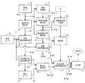
図1は、本実施形態の傾斜角検出に使用される前記ECU2の機能を示すブロック図である。図1において、旋回半径算出部6は、舵角センサ4で検出された舵角θsに基づいて定常旋回半径rsを算出する。定常旋回半径rsは上述のようにマップを用いて求めてもよいし、予め実測によって得た舵角θsと旋回半径rsとの関係に基づく関数式を使用してもよい。また、舵角センサ4の検出出力は、舵角記憶部7に入力され、前回検出舵角θs-1として記憶される。
FIG. 1 is a block diagram showing functions of the ECU 2 used for detecting an inclination angle according to the present embodiment. In FIG. 1, the turning
定常傾斜角算出部8は、推定旋回半径rsと車速センサ3で検出された車速vとに基づいて定常推定傾斜角θbsを算出する。定常推定傾斜角θbsは上述のようにマップを用いて求めてもよいし、予め実測によって得た定常旋回半径rsおよび車速vと定常推定傾斜角θbsとの関係に基づく関数式を使用してもよい。
The steady inclination
推定横方向加速度算出部9は、車速vと定常傾斜角θbsとに基づいて横方向加速度gsを推定する。差分G算出部10は横Gセンサ5によって検出された横方向加速度gと前記推定された横方向加速度gsとの差を算出する。
The estimated lateral acceleration calculation unit 9 estimates the lateral acceleration gs based on the vehicle speed v and the steady inclination angle θbs. The difference
補正過渡傾斜角算出部11は、定常傾斜角θbsと横方向加速度の差(gs−g)とに基づいて、横G補正過渡傾斜角θbgを算出する。
The corrected transient tilt
舵角変化量算出部12は、今回検出された舵角θsと前回検出された舵角θs-1との差により、舵角変化量Δθsを算出する。過渡旋回半径算出部13は、舵角θsと舵角の変化量Δθsとに基づいて過渡推定旋回半径rdを算出する。過渡傾斜角算出部14は、過渡旋回半径rdと車速vとに基づいて過渡傾斜角θbdを算出する。
The steering angle change
舵角変化量判別部15は舵角θsの変化量Δθsと所定値Kとの大小を比較し、比較結果は選択部16に入力される。選択部16は舵角の変化量Δθsが所定値Kより大きい結果のときは、過渡傾斜角算出部14を付勢し、舵角の変化量Δθsが所定値より小さい結果のときは、補正過渡傾斜角算出部11を付勢する。
The steering angle change
出力部17は、定常傾斜角θbs、過渡傾斜角θbd、および横G補正過渡傾斜角θbgにそれぞれ重み付けをして車体傾斜角の算出結果として出力する。
The
本発明を、最良の形態に従って説明したが、本発明はこの実施形態に限定されず、当業者は種々変形が可能である。自動二輪車は運転者が運転姿勢を左右に傾けたり、左右にずらしたりして車体を傾斜させて、旋回動作を行う。このときの車体の傾斜角に関連して舵角が変化する。そして、同じ旋回半径であっても舵角の変化量は車速に応じて変化する。 Although the present invention has been described according to the best mode, the present invention is not limited to this embodiment, and various modifications can be made by those skilled in the art. In a motorcycle, a driver performs a turning operation by tilting the vehicle body by tilting the driving posture to the left or right or shifting it to the left or right. The steering angle changes in relation to the tilt angle of the vehicle body at this time. And even if it is the same turning radius, the variation | change_quantity of a steering angle changes according to a vehicle speed.
つまり傾斜角は、舵角、車速、旋回半径の3元関数であり、この相関性を元に、まず、舵角に応じた旋回半径を求め、その旋回半径と車速とに基づいて傾斜角を求める。この傾斜角は定常旋回時のものなので、過渡旋回時のために舵角変化量や横方向加速度の変化によって定常旋回半径を補正するという手順をとっている。 In other words, the tilt angle is a ternary function of the steering angle, the vehicle speed, and the turning radius. Based on this correlation, first, the turning radius corresponding to the steering angle is obtained, and the inclination angle is determined based on the turning radius and the vehicle speed. Ask. Since this inclination angle is that during steady turning, a procedure is adopted in which the steady turning radius is corrected based on changes in the steering angle change and lateral acceleration for transient turning.
したがって、例えば、高精度の舵角センサを用いることができれば、横Gセンサ5を用いず、定常旋回時の傾斜角度を舵角変化量で補正して、過渡旋回一般の傾斜角とすることができる。
Therefore, for example, if a highly accurate rudder angle sensor can be used, the inclination angle during steady turning can be corrected with the amount of change in rudder angle without using the
上述の実施形態では、舵角に対する旋回半径の関係はマップとして予め設定させておくようにしたが、本発明はこれに限らず、舵角と旋回半径との関係を関数式として予め設定しておき、その関数式を使用し、演算によって舵角から旋回半径を導出してもよい。 In the above-described embodiment, the relationship between the turning angle and the turning radius is set in advance as a map. However, the present invention is not limited to this, and the relationship between the turning angle and the turning radius is set in advance as a functional equation. Alternatively, the turning radius may be derived from the steering angle by calculation using the function formula.
1…傾斜角検出装置、 2…傾斜角ECU、 3…車速センサ、 4…舵角センサ、 5…横Gセンサ、 6…旋回半径算出部、8…定常傾斜角算出部、 9…推定横方向加速度算出部、 12…舵角変化量算出部、 13…過渡旋回半径算出部、 14…過渡傾斜角算出部、 15…舵角変化量判別部
DESCRIPTION OF
Claims (2)
舵角センサと、
車速センサと、
前記舵角センサで検出された舵角に対応する旋回半径を、予め設定された舵角と旋回半径との関係の実測値に基づいて算出する旋回半径算出手段と、
前記旋回半径算出手段で算出された旋回半径および車速センサで検出された車速に基づいて定常旋回時の車体傾斜角を求める傾斜角算出手段とを具備し、
前記旋回半径算出手段が、舵角と旋回半径との関係を予め設定した舵角/旋回半径マップまたは関数を有しており、
前記舵角センサで検出された舵角を使用して前記舵角/旋回半径マップを検索または関数を使用して旋回半径を得るように構成されているとともに、
前記傾斜角算出手段が、旋回半径と車速と車体傾斜角との関係を予め設定した車速/傾斜角マップまたは関数を有しており、
前記旋回半径算出手段で算出された旋回半径および前記車速センサで検出された車速を使用して前記車速/傾斜角マップを検索または関数を使用して車体傾斜角を得るように構成されており、
さらに、
前記舵角センサで検出された舵角の変化量を算出する舵角変化量算出手段と、
前記舵角の変化量が所定値以上かどうかを判別する舵角変化量判別部と、
前記舵角変化量判別部で、舵角の変化量が所定値以上であると判別された場合に、前記傾斜角算出手段で算出された定常旋回時の車体傾斜角を、舵角および舵角の変化量、並びに車速に基づいて補正し、過渡旋回時の車体傾斜角を算出する過渡傾斜角算出手段とを具備していることを特徴とする自動二輪車の傾斜角検出装置。 In the inclination angle detection device for motorcycles,
Rudder angle sensor,
A vehicle speed sensor,
A turning radius calculating means for calculating a turning radius corresponding to the rudder angle detected by the rudder angle sensor based on a measured value of a relationship between a preset rudder angle and the turning radius;
Inclination angle calculation means for obtaining a vehicle body inclination angle during steady turning based on the turning radius calculated by the turning radius calculation means and the vehicle speed detected by the vehicle speed sensor ,
The turning radius calculation means has a steering angle / turning radius map or function in which the relationship between the steering angle and the turning radius is preset,
The steering angle detected by the steering angle sensor is used to search the steering angle / turning radius map or to use a function to obtain the turning radius;
The inclination angle calculating means has a vehicle speed / inclination angle map or function in which a relationship between a turning radius, a vehicle speed, and a vehicle body inclination angle is preset.
Searching the vehicle speed / tilt angle map using the turning radius calculated by the turning radius calculating means and the vehicle speed detected by the vehicle speed sensor or obtaining a vehicle body inclination angle using a function,
further,
Rudder angle change amount calculating means for calculating a change amount of the rudder angle detected by the rudder angle sensor;
A rudder angle change amount determining unit for determining whether or not the rudder angle change amount is a predetermined value or more;
When the rudder angle change amount discriminating unit determines that the rudder angle change amount is equal to or greater than a predetermined value, the vehicle body tilt angle at the time of steady turning calculated by the tilt angle calculating unit is used as the rudder angle and the rudder angle. An inclination angle detecting device for a motorcycle, comprising: a transient inclination angle calculating means for correcting the vehicle body inclination angle at the time of transient turning by correcting the change amount of the vehicle and the vehicle speed .
舵角センサと、
車速センサと、
前記舵角センサで検出された舵角に対応する旋回半径を、予め設定された舵角と旋回半径との関係の実測値に基づいて算出する旋回半径算出手段と、
前記旋回半径算出手段で算出された旋回半径および車速センサで検出された車速に基づいて定常旋回時の車体傾斜角を求める傾斜角算出手段とを具備し、
前記旋回半径算出手段が、舵角と旋回半径との関係を予め設定した舵角/旋回半径マップまたは関数を有しており、
前記舵角センサで検出された舵角を使用して前記舵角/旋回半径マップを検索または関数を使用して旋回半径を得るように構成されているとともに、
前記傾斜角算出手段が、旋回半径と車速と車体傾斜角との関係を予め設定した車速/傾斜角マップまたは関数を有しており、
前記旋回半径算出手段で算出された旋回半径および前記車速センサで検出された車速を使用して前記車速/傾斜角マップを検索または関数を使用して車体傾斜角を得るように構成されており、
さらに、
前記舵角センサで検出された舵角の変化量を算出する舵角変化量算出手段と、
前記舵角の変化量が所定値以上かどうかを判別する舵角変化量判別部と、
前記舵角変化量判別部で、舵角の変化量が所定値未満であると判別された場合に、車体の幅方向に生じる加速度を検出する加速度センサと、
前記旋回半径算出手段で算出された旋回半径および前記車速センサで検出された車速に基づいて車体の幅方向に生じる加速度を算出する加速度算出手段と、
前記加速度算出手段で算出された加速度および前記加速度センサで検出された加速度の差に基づいて前記傾斜角算出手段で算出された定常旋回時の車体傾斜角を補正して過渡旋回時の車体傾斜角を算出する補正過渡傾斜角算出手段とを具備していることを特徴とする自動二輪車の傾斜角検出装置。 In the inclination angle detection device for motorcycles,
Rudder angle sensor,
A vehicle speed sensor,
A turning radius calculating means for calculating a turning radius corresponding to the rudder angle detected by the rudder angle sensor based on a measured value of a relationship between a preset rudder angle and the turning radius;
Inclination angle calculation means for obtaining a vehicle body inclination angle during steady turning based on the turning radius calculated by the turning radius calculation means and the vehicle speed detected by the vehicle speed sensor,
The turning radius calculation means has a steering angle / turning radius map or function in which the relationship between the steering angle and the turning radius is preset,
The steering angle detected by the steering angle sensor is used to search the steering angle / turning radius map or to use a function to obtain the turning radius;
The inclination angle calculating means has a vehicle speed / inclination angle map or function in which a relationship between a turning radius, a vehicle speed, and a vehicle body inclination angle is preset.
Searching the vehicle speed / tilt angle map using the turning radius calculated by the turning radius calculating means and the vehicle speed detected by the vehicle speed sensor or obtaining a vehicle body inclination angle using a function,
further,
Rudder angle change amount calculating means for calculating a change amount of the rudder angle detected by the rudder angle sensor;
A rudder angle change amount determining unit for determining whether or not the rudder angle change amount is a predetermined value or more;
An acceleration sensor for detecting an acceleration generated in a width direction of the vehicle body when the rudder angle change amount determining unit determines that the change amount of the rudder angle is less than a predetermined value;
Acceleration calculating means for calculating acceleration generated in the width direction of the vehicle body based on the turning radius calculated by the turning radius calculating means and the vehicle speed detected by the vehicle speed sensor;
Based on the difference between the acceleration calculated by the acceleration calculating means and the acceleration detected by the acceleration sensor, the vehicle body inclination angle during steady turning calculated by the inclination angle calculating means is corrected to correct the vehicle body inclination angle during transient turning. An apparatus for detecting an inclination angle of a motorcycle, comprising: a corrected transient inclination angle calculating means for calculating
Priority Applications (3)
| Application Number | Priority Date | Filing Date | Title |
|---|---|---|---|
| JP2007188193A JP5152778B2 (en) | 2007-07-19 | 2007-07-19 | Inclination angle detector for motorcycles |
| US12/214,489 US7822575B2 (en) | 2007-07-19 | 2008-06-19 | Tilt-angle detecting method and apparatus for a motorcycle |
| DE102008033482A DE102008033482B4 (en) | 2007-07-19 | 2008-07-16 | Inclination angle detecting device for a motorcycle |
Applications Claiming Priority (1)
| Application Number | Priority Date | Filing Date | Title |
|---|---|---|---|
| JP2007188193A JP5152778B2 (en) | 2007-07-19 | 2007-07-19 | Inclination angle detector for motorcycles |
Publications (3)
| Publication Number | Publication Date |
|---|---|
| JP2009023485A JP2009023485A (en) | 2009-02-05 |
| JP2009023485A5 JP2009023485A5 (en) | 2010-05-27 |
| JP5152778B2 true JP5152778B2 (en) | 2013-02-27 |
Family
ID=40149317
Family Applications (1)
| Application Number | Title | Priority Date | Filing Date |
|---|---|---|---|
| JP2007188193A Expired - Fee Related JP5152778B2 (en) | 2007-07-19 | 2007-07-19 | Inclination angle detector for motorcycles |
Country Status (3)
| Country | Link |
|---|---|
| US (1) | US7822575B2 (en) |
| JP (1) | JP5152778B2 (en) |
| DE (1) | DE102008033482B4 (en) |
Families Citing this family (12)
| Publication number | Priority date | Publication date | Assignee | Title |
|---|---|---|---|---|
| KR101836242B1 (en) * | 2012-10-26 | 2018-04-19 | 현대자동차 주식회사 | Method and apparatus for measuring tilt angle during turn of vehicle |
| DE102012221188A1 (en) * | 2012-11-20 | 2014-05-22 | Robert Bosch Gmbh | Device, vehicle |
| US9428236B2 (en) | 2013-11-06 | 2016-08-30 | Bryan Goss | Lean-compensating motorcycle with channel wheels |
| US10283007B2 (en) | 2014-06-16 | 2019-05-07 | Honda Motor Co., Ltd. | Training system and method for motorcycle riding |
| US9840239B2 (en) * | 2015-10-13 | 2017-12-12 | Robert Bosch Gmbh | Cornering brake control |
| JP6181798B1 (en) * | 2016-03-31 | 2017-08-16 | 本田技研工業株式会社 | Saddle-type vehicle travel status notification device and straddle-type vehicle travel status detection device |
| JP6658413B2 (en) * | 2016-09-07 | 2020-03-04 | 株式会社デンソー | Object detection device |
| JP6728393B2 (en) * | 2016-11-29 | 2020-07-22 | ヤマハ発動機株式会社 | Angular velocity acquisition device around the vertical axis of the lean vehicle road surface |
| DE102018200406A1 (en) * | 2018-01-11 | 2019-07-11 | Robert Bosch Gmbh | Method for automatically adjusting the speed of a motorcycle during a turning maneuver |
| CN110316196B (en) * | 2018-03-28 | 2022-11-11 | 奥迪股份公司 | Driving assistance system and method |
| JP7185517B2 (en) * | 2018-12-18 | 2022-12-07 | カワサキモータース株式会社 | Control device for hybrid lean vehicle |
| WO2021064804A1 (en) | 2019-09-30 | 2021-04-08 | 本田技研工業株式会社 | Estimation device and saddle-type vehicle |
Family Cites Families (8)
| Publication number | Priority date | Publication date | Assignee | Title |
|---|---|---|---|---|
| JPH02189295A (en) * | 1989-01-19 | 1990-07-25 | Honda Motor Co Ltd | Motorcycle |
| DE69104938T2 (en) * | 1990-08-15 | 1995-03-23 | Honda Motor Co Ltd | Control device for two-wheeled vehicle. |
| JP2854441B2 (en) * | 1990-08-15 | 1999-02-03 | 本田技研工業株式会社 | Motorcycle control device |
| JP3046866B2 (en) | 1991-11-14 | 2000-05-29 | ヤマハ発動機株式会社 | Motorcycle inclination angle detection device |
| JP2001219881A (en) * | 2000-02-09 | 2001-08-14 | Yamaha Motor Co Ltd | Control device for saddle riding vehicle |
| DE10350047A1 (en) | 2003-10-27 | 2005-05-25 | Schubach, Rudolf, Dipl.-Ing. | Motor bike bend lend angle and instantaneous speed sensor unit for brake and slip control has main axis rotation rate and longitudinal acceleration sensors integrated in single component |
| DE102004060292A1 (en) | 2004-12-15 | 2006-07-06 | Robert Bosch Gmbh | Tilt angle determination for a motorcycle |
| DE102005002239A1 (en) * | 2005-01-18 | 2006-07-20 | Robert Bosch Gmbh | Method for detection of lateral position of vehicle, involves acceleration sensor which is mounted in such a way that its measuring device is oriented parallel to the vertical axis of vehicle |
-
2007
- 2007-07-19 JP JP2007188193A patent/JP5152778B2/en not_active Expired - Fee Related
-
2008
- 2008-06-19 US US12/214,489 patent/US7822575B2/en not_active Expired - Fee Related
- 2008-07-16 DE DE102008033482A patent/DE102008033482B4/en not_active Expired - Fee Related
Also Published As
| Publication number | Publication date |
|---|---|
| DE102008033482A1 (en) | 2009-01-22 |
| DE102008033482B4 (en) | 2013-05-16 |
| US20090024350A1 (en) | 2009-01-22 |
| JP2009023485A (en) | 2009-02-05 |
| US7822575B2 (en) | 2010-10-26 |
Similar Documents
| Publication | Publication Date | Title |
|---|---|---|
| JP5152778B2 (en) | Inclination angle detector for motorcycles | |
| US8989913B2 (en) | Travel route estimation device and travel route estimation method used in the same device | |
| CN110234957B (en) | Method for storing travel record, method for generating travel track model, method for estimating self-position, and device for storing travel record | |
| KR20140093961A (en) | Sensor system for independently evaluating the accuracy of the data of the sensor system | |
| JP6936658B2 (en) | Vehicle driving support device | |
| JPH06104455B2 (en) | Vehicle motion condition estimation device | |
| WO2010084994A1 (en) | Driver operation prediction device, method, and driver operation prediction program | |
| JP2009023485A5 (en) | ||
| US8364348B2 (en) | Method and device for determining a steering angle offset | |
| JPH0814490B2 (en) | In-vehicle navigation system | |
| JP2004148910A (en) | Detection device for lowering of air pressure and correction method of sensor performed using the detection device | |
| US9605958B2 (en) | Method and device for determining the inclined position of a vehicle | |
| JP6590988B1 (en) | Lane marking recognition system | |
| JP5189316B2 (en) | Yaw rate sensor output determination device and following vehicle determination device | |
| JP3552267B2 (en) | Vehicle position detection device | |
| KR102158745B1 (en) | Device for correcting the obstacle detection on the curve road and method thereof | |
| JP5682302B2 (en) | Traveling road estimation device, method and program | |
| KR101244475B1 (en) | Method and System for Controlling Parking | |
| JP2017122741A (en) | Determination device, determination method, determination program, and recording medium | |
| JP2013250167A (en) | Distance measuring device, distance correction method, distance correction program, and recording medium | |
| JP6173714B2 (en) | In-vehicle device, position correction method thereof, and position correction program | |
| JP2016122022A (en) | Determination device, determination method, determination program, and recording medium | |
| JPH1062450A (en) | Yaw rate sensor neutral point estimator | |
| JP5454190B2 (en) | Vehicle control device | |
| JP5120034B2 (en) | Vehicle traveling direction estimation device |
Legal Events
| Date | Code | Title | Description |
|---|---|---|---|
| A521 | Written amendment |
Free format text: JAPANESE INTERMEDIATE CODE: A523 Effective date: 20100408 |
|
| A621 | Written request for application examination |
Free format text: JAPANESE INTERMEDIATE CODE: A621 Effective date: 20100408 |
|
| A131 | Notification of reasons for refusal |
Free format text: JAPANESE INTERMEDIATE CODE: A131 Effective date: 20120613 |
|
| A521 | Written amendment |
Free format text: JAPANESE INTERMEDIATE CODE: A523 Effective date: 20120810 |
|
| TRDD | Decision of grant or rejection written | ||
| A01 | Written decision to grant a patent or to grant a registration (utility model) |
Free format text: JAPANESE INTERMEDIATE CODE: A01 Effective date: 20121107 |
|
| A61 | First payment of annual fees (during grant procedure) |
Free format text: JAPANESE INTERMEDIATE CODE: A61 Effective date: 20121128 |
|
| FPAY | Renewal fee payment (event date is renewal date of database) |
Free format text: PAYMENT UNTIL: 20151214 Year of fee payment: 3 |
|
| R150 | Certificate of patent or registration of utility model |
Ref document number: 5152778 Country of ref document: JP Free format text: JAPANESE INTERMEDIATE CODE: R150 Free format text: JAPANESE INTERMEDIATE CODE: R150 |
|
| LAPS | Cancellation because of no payment of annual fees |