JP5149040B2 - Elevator equipment - Google Patents
Elevator equipment Download PDFInfo
- Publication number
- JP5149040B2 JP5149040B2 JP2008055236A JP2008055236A JP5149040B2 JP 5149040 B2 JP5149040 B2 JP 5149040B2 JP 2008055236 A JP2008055236 A JP 2008055236A JP 2008055236 A JP2008055236 A JP 2008055236A JP 5149040 B2 JP5149040 B2 JP 5149040B2
- Authority
- JP
- Japan
- Prior art keywords
- groove
- door
- sill
- closing plate
- elevator apparatus
- Prior art date
- Legal status (The legal status is an assumption and is not a legal conclusion. Google has not performed a legal analysis and makes no representation as to the accuracy of the status listed.)
- Active
Links
- 230000001174 ascending effect Effects 0.000 claims 1
- 238000013459 approach Methods 0.000 description 3
- 230000003014 reinforcing effect Effects 0.000 description 3
- 230000006835 compression Effects 0.000 description 1
- 238000007906 compression Methods 0.000 description 1
- 230000000694 effects Effects 0.000 description 1
- 239000007787 solid Substances 0.000 description 1
Images


Landscapes
- Elevator Door Apparatuses (AREA)
Description
この発明は、エレベータ装置に関し、特に敷居の溝内に異物が挟まれないエレベータ装置に関するものである。 The present invention relates to an elevator apparatus, and more particularly to an elevator apparatus in which foreign matter is not caught in a groove of a sill.
敷居溝内への異物の混入を未然に防止して、異物により戸の開閉ができなくなるのを防止するために、一方の戸の下端部にゴムベルト等からなる閉塞帯の一端部を固定するとともに、この閉塞帯を他方の戸の下端部の滑車に巻き掛けて、戸開時に敷居溝内に閉塞帯を敷設して敷設溝を閉塞するようにし、また、滑車に巻き掛けられた閉塞帯の他端部には、重りを吊り下げて、閉塞帯に張力を与えるとともに、戸閉時に重りの重量により閉塞帯を戸側へ収納するようにすることが提案されている(例えば、特許文献1参照)。 In order to prevent foreign matter from entering the sill groove and prevent the foreign matter from opening and closing the door, one end of a closing belt made of a rubber belt or the like is fixed to the lower end of one door. Wrap this closure band around the pulley at the lower end of the other door so that when the door is open, the closure band is laid in the sill groove to close the laying groove. It has been proposed that a weight is suspended from the other end to apply tension to the closing band, and that the closing band is housed on the door side by the weight of the weight when the door is closed (for example, Patent Document 1). reference).
また、案内溝内の全域に亘って、足部の摺動に応じて圧縮変形と塑性変形を行う弾性を有するスポンジと、スポンジの表面に接着された耐摩耗性を有する補強部材とにより構成された溝塞ぎ手段が設けられていて、足部の位置しない部分で補強部材の上面と敷居部の上面とが同一平面になるように構成されている(例えば、特許文献2参照)。 In addition, it is composed of an elastic sponge that performs compression deformation and plastic deformation according to the sliding of the foot over the entire area in the guide groove, and a wear-resistant reinforcing member that is bonded to the surface of the sponge. The groove closing means is provided, and the upper surface of the reinforcing member and the upper surface of the sill portion are configured to be flush with each other at the portion where the foot portion is not located (see, for example, Patent Document 2).
しかし、特許文献1のように戸の内部に滑車や重りを設けるとともに両方の戸の間に閉塞帯を敷設しなければならず、構造が複雑であるとともに高価であるという問題がある。
また、特許文献2のように案内溝内が耐摩耗性を有する補強部材で表面が覆われたスポンジにより埋められるが、戸の繰り返し開閉による変形によりクリープすることを防止できるスポンジは高価であるとともに、案内溝内がスポンジのような固体で埋められているので戸の移動がスムーズでないという問題がある。
However, as in Patent Document 1, a pulley and a weight must be provided inside the door, and a closing band must be laid between both doors, which causes a problem that the structure is complicated and expensive.
Further, as in
この発明の目的は、戸の移動を案内する敷居の溝の中に異物が入り込まないよう安価に対処されたエレベータ装置を提供することである。 An object of the present invention is to provide an elevator apparatus that is inexpensively dealt with so that foreign matter does not enter a groove of a sill that guides the movement of a door.
この発明に係るエレベータ装置は、敷居の溝に沿って開閉される戸を備えるエレベータ装置において、上記戸が全開位置に位置しているとき上記敷居の溝を塞ぐ上昇位置と上記戸が上記敷居の溝内を移動するとき移動を妨げない下降位置との間で上下移動する溝塞ぎ板と、上記全開位置までに移動する上記戸により回転されて上記溝塞ぎ板を上記上昇位置まで押し上げるレバー機構と、を備える。 The elevator apparatus according to the present invention is an elevator apparatus including a door that is opened and closed along a groove in the sill, and when the door is in a fully open position, the lift position that closes the groove in the sill and the door is in the sill A groove closing plate that moves up and down between a lowered position that does not impede movement when moving in the groove, and a lever mechanism that is rotated by the door that moves to the fully open position to push the groove closing plate to the raised position .
この発明に係るエレベータ装置の効果は、上昇位置に位置するとき敷居の溝を塞ぐとともに下降位置に位置するとき戸が敷居の溝内を移動することを妨げないよう溝の底に退避する溝塞ぎ板と、戸が全開位置に近づいたとき溝塞ぎ板を押し上げるレバー機構と、を備えるので、敷居の溝に異物が入り込みことを溝塞ぎ板とレバー機構という簡単な部材で安価に防止できることである。 The effect of the elevator apparatus according to the present invention is to close the groove of the sill when positioned in the raised position and to close the groove so as not to prevent the door from moving in the groove of the sill when positioned in the lowered position. And a lever mechanism that pushes up the groove closing plate when the door approaches the fully open position, so that foreign matter can enter into the groove of the sill with a simple member such as the groove closing plate and the lever mechanism. .
実施の形態1.
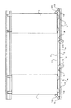
図1〜図3は、この発明の実施の形態1に係るエレベータ装置の乗りカゴの戸の正面図である。なお、図1の戸は全開位置に位置し、図2の戸は全閉位置に位置し、図3の戸は戸当たり具に当接するときに位置している。
この発明の実施の形態1に係るエレベータ装置は、溝3が設けられたそれぞれの敷居2に水平移動が案内されるエレベータの乗りカゴの戸1および各乗場の戸を具備している。なお、以下の説明では、エレベータの乗りカゴの戸1に関わる内容について説明するが、各乗場の戸に関わる内容も同様であるので説明は省略する。また、両開き戸である戸1に関して説明するが、片開き戸である戸1であっても同様に適用することができる。
そして、この発明の実施の形態1に係るエレベータ装置は、図1に示すように、エレベータの乗りカゴの戸1が全開位置に位置しているとき敷居2の溝3を塞ぐ溝塞ぎ部材4および開閉する戸1により溝塞ぎ部材4を移動するレバー機構5を備える。
Embodiment 1 FIG.
1 to 3 are front views of a door of a passenger car of the elevator apparatus according to Embodiment 1 of the present invention. 1 is located at the fully open position, the door of FIG. 2 is located at the fully closed position, and the door of FIG. 3 is located when contacting the door stop.
The elevator apparatus according to the first embodiment of the present invention includes an elevator car door 1 and a landing door that are guided to move horizontally to each
As shown in FIG. 1, the elevator apparatus according to Embodiment 1 of the present invention includes a groove closing member 4 that closes the groove 3 of the
この発明の実施の形態1に係る溝塞ぎ部材4は、戸1が全開位置に位置するとき開いた乗降口に現れた敷居2の溝3の上面を塞ぎ、且つ戸1が全閉位置に位置するとき敷居2の溝3の底3aに退避する溝塞ぎ板11、および、溝塞ぎ板11の下面から下方に延びるとともに敷居2の溝3の底3aに設けられた孔3bを貫通するガイド棒12から構成されている。
The groove closing member 4 according to the first embodiment of the present invention closes the upper surface of the groove 3 of the
この発明の実施の形態1に係るレバー機構5は、全開位置に位置する戸1の下側に略水平に置かれるレバー14、レバー14の一端部に固定される戸当たり具15、レバー14と戸当たり具15とが固定された箇所を回転自在に支持する支持軸16、レバー14の他端部に固定されるとともに溝塞ぎ板11を下側から支持するせり上げ具17、および、レバー14が略水平位置から傾くとき戸当たり具15が当接してレバー14の傾きを制限するストッパー18から構成されている。
The
支持軸16は、全開位置に位置する戸1に対して戸開方向の先方に設けられ、戸当たり具15は、支持軸16を中心として戸閉方向に傾いている。
レバー14は、戸当たり具15がストッパー18に当接しているときには支持軸16を中心としてせり上げ具17が固定されている他端部が下降する。他方、レバー14は、全開位置に位置する戸1により戸当たり具15が戸開方向に立たされたときには支持軸16を中心としてせり上げ具17が固定されている他端部が上昇する。
せり上げ具17は、敷居2の溝3の深さを30mmとすると約30mm上下するので、せり上げ具17が固定されているレバー14の他端部を30mm上下させなければならない。そこで、レバー14の長さを1100mmとすると、レバー14を支持軸16を中心として角度1.56度回転しなければならない。そのため、ストッパー18に当接している戸当たり具15は全開位置に移動する手前の戸1により戸開方向に角度1.56度起こされる。
The
When the
The
溝塞ぎ板11は、せり上げ具17が下降位置に位置しているときには自重により敷居2の溝3の底3aまで下降し、せり上げ具17が上昇位置に位置しているときにはせり上げ具17により押し上げられる力が加えられ、敷居2の溝3の上面を塞ぐ位置に保持されている。
ガイド棒12は、溝塞ぎ板11がせり上げ具17により押し上げられるときと溝塞ぎ板11が自重で降下するとき、孔3bに案内されて溝塞ぎ板11を上下方向だけにガイドする。
The
The
次に、戸1が開閉する際の溝塞ぎ部材4およびレバー機構5の動作について説明する。
戸1が全閉位置に位置しているとき、図2に示すように、戸当たり具15がストッパー18に当接することにより、レバー14はせり上げ具17が固定された他端部が下降してせり上げ具17が下降位置に停止している。また、溝塞ぎ板11は自重により敷居2の溝3の底3aに置かれる。
次に、戸1が戸開移動を開始しても、図3に示すように、戸1が戸当たり具15に当たるまでは溝塞ぎ板11は敷居2の溝3の底3aに置かれている。
戸1が戸当たり具15に当たり戸当たり具15を戸開方向に傾きを起こすとレバー14の他端部が上昇し、他端部に固定されたせり上げ具17も上昇するので、溝塞ぎ板11が上昇する。
戸1が全開位置に達すると、図1に示すように、溝塞ぎ板11が敷居2の溝3の縁まで上昇する。このように、敷居2の溝3の縁と同じ上面で溝3が塞がれているので、乗客が乗り降りしたときに敷居2上に動いた異物は溝3の中に入り込むことが防げる。
Next, the operation of the groove closing member 4 and the
When the door 1 is located at the fully closed position, as shown in FIG. 2, the door stopper 15 abuts against the
Next, even if the door 1 starts the door opening movement, as shown in FIG. 3, the
When the door 1 hits the door stop 15 and tilts the door stop 15 in the door opening direction, the other end of the
When the door 1 reaches the fully open position, the
この発明の実施の形態1に係るエレベータ装置では、上昇位置に位置するとき敷居2の溝3を塞ぐとともに下降位置に位置するとき戸1が敷居2の溝3内を移動することを妨げないよう溝3の底3aに置かれる溝塞ぎ板11と、戸1が全開位置に近づいたとき溝塞ぎ板11を押し上げるレバー機構5を備えるので、敷居2の溝3に異物が入り込みことを溝塞ぎ板11とレバー機構5という簡単な部材で安価に防止できる。
In the elevator apparatus according to the first embodiment of the present invention, the groove 1 of the
実施の形態2.
図4は、この発明の実施の形態2に係るエレベータ装置の敷居付近の拡大図である。
この発明の実施の形態2に係るエレベータ装置は、この発明の実施の形態1に係るエレベータ装置と溝塞ぎ部材4Bが異なり、それ以外は同様であるので、同様な部分に同じ符号を付記し説明は省略する。
この発明の実施の形態2に係る溝塞ぎ部材4Bは、この発明の実施の形態1に係る溝塞ぎ部材4を敷居2に対して弾性的に支持する戻しばね22を追加したことが異なり、それ以外は同様であるので、同様な部分に同じ符号を付記し説明は省略する。
FIG. 4 is an enlarged view of the vicinity of the threshold of the elevator apparatus according to
The elevator apparatus according to
The
そして、この発明の実施の形態2に係る溝塞ぎ部材4Bは、戸1が全開位置に位置するとき開いた乗降口に現れた敷居2の溝3の上面を塞ぎ、且つ戸1が全閉位置に位置するとき敷居2の溝3の底3aまで下降する溝塞ぎ板11、溝塞ぎ板11の下面から下方に延びるとともに敷居2の溝3の底3aに設けられた孔3bを貫通するガイド棒12、ガイド棒12の下端面に固定された受板21、および、敷居2の溝3の底3aの裏面と受板21とに両端が当接される戻しばね22から構成されている。
And the
溝塞ぎ板11は、せり上げ具17が下降位置に位置しているときには戻しばね22の付勢力により敷居2の溝3の底3aまで下降され、せり上げ具17が上昇位置に位置しているときにはせり上げ具17により戻しばね22の付勢力に抗する力が加えられ、敷居2の溝3の上面を塞ぐ位置に保持されている。
The
次に、戸1が開閉する際の溝塞ぎ部材4Bおよびレバー機構5の動作について説明する。
戸1が全閉位置に位置しているとき、図4に示すように、戸当たり具15がストッパー18に当接することにより、レバー14はせり上げ具17が固定された他端部が下降してせり上げ具17が下降位置に停止している。また、溝塞ぎ板11は戻しばね22により敷居2の溝3の底3aに押し付けられている。
次に、戸1が戸開移動を開始しても、戸1が戸当たり具15に当たるまでは溝塞ぎ板11は戻りばね22により敷居2の溝3の底3aに押し付けられている。
戸1が戸当たり具15に当たり戸当たり具15を戸開方向に傾きを起こすとレバー14の他端部が上昇し、他端部に固定されたせり上げ具17も上昇するので、戻しばね22の付勢力に抗して溝塞ぎ板11が上昇する。
戸1が全開位置に達すると、図5に示すように、溝塞ぎ板11が敷居2の溝3の縁まで上昇するとともに戻しばね22の付勢力によりその上昇位置に保持される。このように、敷居2の溝3の縁と同じ上面で溝3が塞がれているので、乗客が乗り降りしたときに敷居2上に動いた異物は溝3の中に入り込むことが防げる。
Next, the operation of the
When the door 1 is located at the fully closed position, as shown in FIG. 4, the door stopper 15 abuts against the
Next, even if the door 1 starts the door opening movement, the
When the door 1 hits the door stop 15 and tilts the door stop 15 in the door opening direction, the other end of the
When the door 1 reaches the fully open position, the
この発明の実施の形態2に係るエレベータ装置では、上昇位置に位置するとき敷居2の溝3を塞ぐとともに下降位置に位置するとき戸1が敷居2の溝3内を移動することを妨げないよう溝3の底3aに置かれる溝塞ぎ板11と、戸1が全開位置に近づいたとき溝塞ぎ板11を押し上げるレバー機構5を備えるので、敷居2の溝3に異物が入り込みことを溝塞ぎ板11とレバー機構5という簡単な部材で安価に防止できる。
また、戻しばね22により溝塞ぎ板11が付勢され、せり上げ具17が下がったときには付勢力により溝塞ぎ板11が速やかに溝3の底3aに退避させられるので、溝塞ぎ板11が溝3の中途半端な深さのところに留まることがなく、戸1の移動を妨げることがない。
In the elevator apparatus according to
Further, when the
1 戸、2 敷居、3 溝、3a (溝の)底、3b (溝の底に空けられた)孔、4、4B 溝塞ぎ部材、5 レバー機構、11 溝塞ぎ板、12 ガイド棒、14 レバー、15 戸当たり具、16 支持軸、17 せり上げ具、18 ストッパー、21 受板、22 戻しばね。 1 house, 2 sills, 3 grooves, 3a (groove) bottom, 3b (spaced at the bottom of the groove), 4, 4B groove closing member, 5 lever mechanism, 11 groove closing plate, 12 guide rod, 14 lever , 15 door stopper, 16 support shaft, 17 lifting tool, 18 stopper, 21 backing plate, 22 return spring.
Claims (2)
上昇位置と下降位置との間で上下移動する溝塞ぎ板と、
上記溝塞ぎ板を上記上昇位置まで押し上げるレバー機構と、
を備え、
上記溝塞ぎ板は、上記下降位置では、上記戸が上記敷居の溝内を移動するとき該戸の移動を妨げないように上記溝の底に退避しており、
上記溝塞ぎ板は、上記上昇位置では、上記敷居の溝の上面を塞ぎ、
上記レバー機構は、戸当たり具と、該戸当たり具により回転されて上記溝塞ぎ板を上記上昇位置まで押し上げるレバーとを少なくとも含み、
上記戸当たり具は、全開位置に位置する上記戸に対して戸開方向の先方に設けられている、
ことを特徴とするエレベータ装置。 In an elevator apparatus comprising a door that opens and closes along a groove in the threshold,
A groove closing plate that moves up and down between an ascending position and a descending position;
A lever mechanism that pushes up the groove closing plate to the raised position;
With
In the lowered position, the groove closing plate is retracted to the bottom of the groove so as not to hinder the movement of the door when the door moves in the groove of the sill,
The groove closing plate closes the upper surface of the sill groove at the raised position,
The lever mechanism includes at least a door stopper and a lever that is rotated by the door stopper to push up the groove closing plate to the raised position,
The door stopper is provided in the door opening direction with respect to the door located at the fully open position,
An elevator apparatus characterized by that.
Priority Applications (1)
| Application Number | Priority Date | Filing Date | Title |
|---|---|---|---|
| JP2008055236A JP5149040B2 (en) | 2008-03-05 | 2008-03-05 | Elevator equipment |
Applications Claiming Priority (1)
| Application Number | Priority Date | Filing Date | Title |
|---|---|---|---|
| JP2008055236A JP5149040B2 (en) | 2008-03-05 | 2008-03-05 | Elevator equipment |
Publications (2)
| Publication Number | Publication Date |
|---|---|
| JP2009208930A JP2009208930A (en) | 2009-09-17 |
| JP5149040B2 true JP5149040B2 (en) | 2013-02-20 |
Family
ID=41182468
Family Applications (1)
| Application Number | Title | Priority Date | Filing Date |
|---|---|---|---|
| JP2008055236A Active JP5149040B2 (en) | 2008-03-05 | 2008-03-05 | Elevator equipment |
Country Status (1)
| Country | Link |
|---|---|
| JP (1) | JP5149040B2 (en) |
Families Citing this family (2)
| Publication number | Priority date | Publication date | Assignee | Title |
|---|---|---|---|---|
| JP2011011903A (en) * | 2009-07-06 | 2011-01-20 | Mitsubishi Electric Corp | Sill device for elevator |
| JP6444280B2 (en) * | 2015-08-04 | 2018-12-26 | 三菱電機ビルテクノサービス株式会社 | Escalator dress forced extrusion equipment |
Family Cites Families (2)
| Publication number | Priority date | Publication date | Assignee | Title |
|---|---|---|---|---|
| JPS5261069U (en) * | 1975-10-29 | 1977-05-04 | ||
| JPS61130582U (en) * | 1985-02-01 | 1986-08-15 |
-
2008
- 2008-03-05 JP JP2008055236A patent/JP5149040B2/en active Active
Also Published As
| Publication number | Publication date |
|---|---|
| JP2009208930A (en) | 2009-09-17 |
Similar Documents
| Publication | Publication Date | Title |
|---|---|---|
| US8689945B2 (en) | Device for preventing travel of an elevator with its doors open | |
| US10597259B2 (en) | Elevator apparatus with seal member and link mechanism | |
| JP4644721B2 (en) | Elevator doorway device | |
| JP2018095457A (en) | Elevator apparatus | |
| JP5149040B2 (en) | Elevator equipment | |
| JP2017088367A (en) | Elevator apparatus | |
| US9643820B2 (en) | Device for preventing travel of an elevator with its doors open | |
| JPWO2007039931A1 (en) | Elevator door equipment | |
| KR100867847B1 (en) | Stopper for door window regulator in vehicle | |
| JP6229946B2 (en) | Elevator door opening and closing device | |
| JP6306125B1 (en) | Elevator equipment | |
| JP6270940B1 (en) | Elevator equipment | |
| KR20080082879A (en) | Device for guiding a front door of elevator | |
| JP2009155033A (en) | Elevator door device | |
| JP5932081B1 (en) | Elevator running clearance occlusion device | |
| JP2006096488A (en) | Elevator door device | |
| KR20100006592U (en) | Safety Device For Hatch Door Of Elevator | |
| KR200485400Y1 (en) | Rotation type apparatus for preventing a finger from inserting in a door of elevator | |
| JP5137645B2 (en) | Elevator equipment | |
| JP2011098837A (en) | Apparatus for preventing elevator from moving with door opened | |
| JP6026633B1 (en) | Elevator equipment | |
| JP2009052307A (en) | Door guide rail of mechanical parking device | |
| JP4383774B2 (en) | Elevator door shielding device | |
| JP6258129B2 (en) | Lifting device for small luggage | |
| JP4694302B2 (en) | Elevator landing door smoke barrier |
Legal Events
| Date | Code | Title | Description |
|---|---|---|---|
| A621 | Written request for application examination |
Free format text: JAPANESE INTERMEDIATE CODE: A621 Effective date: 20100222 |
|
| A131 | Notification of reasons for refusal |
Free format text: JAPANESE INTERMEDIATE CODE: A131 Effective date: 20120221 |
|
| A977 | Report on retrieval |
Free format text: JAPANESE INTERMEDIATE CODE: A971007 Effective date: 20120223 |
|
| A521 | Request for written amendment filed |
Free format text: JAPANESE INTERMEDIATE CODE: A523 Effective date: 20120410 |
|
| TRDD | Decision of grant or rejection written | ||
| A01 | Written decision to grant a patent or to grant a registration (utility model) |
Free format text: JAPANESE INTERMEDIATE CODE: A01 Effective date: 20121127 |
|
| A61 | First payment of annual fees (during grant procedure) |
Free format text: JAPANESE INTERMEDIATE CODE: A61 Effective date: 20121129 |
|
| R150 | Certificate of patent or registration of utility model |
Ref document number: 5149040 Country of ref document: JP Free format text: JAPANESE INTERMEDIATE CODE: R150 Free format text: JAPANESE INTERMEDIATE CODE: R150 |
|
| FPAY | Renewal fee payment (event date is renewal date of database) |
Free format text: PAYMENT UNTIL: 20151207 Year of fee payment: 3 |
|
| R250 | Receipt of annual fees |
Free format text: JAPANESE INTERMEDIATE CODE: R250 |
|
| R250 | Receipt of annual fees |
Free format text: JAPANESE INTERMEDIATE CODE: R250 |
|
| R250 | Receipt of annual fees |
Free format text: JAPANESE INTERMEDIATE CODE: R250 |
|
| R250 | Receipt of annual fees |
Free format text: JAPANESE INTERMEDIATE CODE: R250 |
|
| S533 | Written request for registration of change of name |
Free format text: JAPANESE INTERMEDIATE CODE: R313533 |
|
| R350 | Written notification of registration of transfer |
Free format text: JAPANESE INTERMEDIATE CODE: R350 |
|
| R250 | Receipt of annual fees |
Free format text: JAPANESE INTERMEDIATE CODE: R250 |