JP5147546B2 - Video encoding device and video decoding device - Google Patents
Video encoding device and video decoding device Download PDFInfo
- Publication number
- JP5147546B2 JP5147546B2 JP2008141905A JP2008141905A JP5147546B2 JP 5147546 B2 JP5147546 B2 JP 5147546B2 JP 2008141905 A JP2008141905 A JP 2008141905A JP 2008141905 A JP2008141905 A JP 2008141905A JP 5147546 B2 JP5147546 B2 JP 5147546B2
- Authority
- JP
- Japan
- Prior art keywords
- image
- video
- prediction
- picture
- encoding
- Prior art date
- Legal status (The legal status is an assumption and is not a legal conclusion. Google has not performed a legal analysis and makes no representation as to the accuracy of the status listed.)
- Expired - Fee Related
Links
Images


Description
本発明は、映像符号化装置及び映像復号化装置に関する。 The present invention relates to a video encoding device and a video decoding device .
動画像の符号化方式の1つにMPEG−4 AVC(ISO/IEC 14496−10)があり、デジタル・テレビ放送や映像記録メディアに採用されている。MPEG−4 AVCでは、コンテキスト適応型のエントロピー符号化方式を採用することで符号化効率を高めている。コンテキスト適応型のエントロピー符号化方式には、コンテキスト適応型可変長符号化(CAVLC:Context-based Adaptive Variable Length Coding)や、コンテキスト適応型2値算術符号化(CABAC:Context-based Adaptive Binary Arithmetic Coding)がある。 MPEG-4 AVC (ISO / IEC 14496-10) is one of the moving image encoding systems, and is adopted in digital television broadcasting and video recording media. In MPEG-4 AVC, encoding efficiency is improved by adopting a context-adaptive entropy encoding method. Context-adaptive entropy coding methods include context-adaptive variable-length coding (CAVLC) and context-adaptive binary arithmetic coding (CABAC). There is.
こうしたコンテキスト適応型エントロピー符号化は、符号化対象マクロブロックの周辺マクロブロック情報に応じて符号化効率の良い符号化方式を適応的に選択する。そのため、復号化時には復号化対象マクロブロックの周辺マクロブロック情報が必要になる。何らかの要因により符号化データにエラーが発生した場合、同一スライス内ではそれ以降の復号化処理を行うことが極めて困難になる。 Such context adaptive entropy coding adaptively selects a coding scheme with good coding efficiency in accordance with the surrounding macroblock information of the macroblock to be coded. Therefore, peripheral macroblock information of the decoding target macroblock is necessary at the time of decoding. When an error occurs in the encoded data due to some factor, it is extremely difficult to perform subsequent decoding processing in the same slice.
こうした観点から、MPEG−4 AVCでは、エラー耐性を強化する種々のエラー耐性ツールセットが用意されている。例えば、ASO(ArbitrarySliceOrder)は、画面内のスライスを任意の順序で符号化・伝送を可能にする。FMO(FlexibleMacroblockOrdering)は、スライス内のマクロブロック順序を選択可能にする。RS(RedundantSlice)は、同じマクロブロックを複数回、符号化可能にする。こうしたエラー耐性ツールを採用することで、エラー耐性を向上させることが可能となる(非特許文献1参照)。 From this point of view, MPEG-4 AVC provides various error tolerance tool sets that enhance error tolerance. For example, ASO (Arbitrary Slice Order) enables encoding and transmission of slices in a screen in an arbitrary order. FMO (FlexibleMacroblockOrdering) makes it possible to select a macroblock order within a slice. RS (Redundant Slice) enables the same macroblock to be encoded a plurality of times. By adopting such an error tolerance tool, error tolerance can be improved (see Non-Patent Document 1).
また、特許文献1には、伝送路のエラー又は画像の動きに応じて、スライス形状を変化させる技術が記載されている。
エラー耐性のためとはいえ、過度にスライス分割を行うことは、符号化効率という観点からは得策ではない。 Although it is for error tolerance, excessive slice division is not a good idea from the viewpoint of coding efficiency.
上述のエラー耐性ツールは、符号化効率を大きく犠牲にすることがある。また、演算量が増大し、そしてエラー補間処理自体が複雑化し、更にはプロファイルやレベルによって対応が規定されているので、実際上、適用が困難な場合も多い。 The error resilience tools described above can greatly sacrifice coding efficiency. In addition, the amount of calculation increases, the error interpolation process itself becomes complicated, and the correspondence is prescribed by the profile and level, so that it is often difficult to apply in practice.
他方、一般的には、直前の参照画像にある画素を使用することで効果的なエラー補間処理を行うことが可能である。しかし、直前の参照画像の画素値を利用する場合、映像シーンの切り替わり目でエラーが発生したときには、以降の画面間予測符号化された画像への影響が大きい。特に、画面内符号化ピクチャであるIピクチャでエラーが発生した場合、GOP(Group Of Pictures)内でシーンチェンジ前後の画素が混ざり合った違和感のある再生映像となってしまうことがある。 On the other hand, in general, it is possible to perform an effective error interpolation process by using a pixel in the immediately preceding reference image. However, when the pixel value of the immediately preceding reference image is used, if an error occurs at the switching point of the video scene, the influence on the subsequent inter-screen predictive encoded image is great. In particular, when an error occurs in an I picture, which is an intra-picture encoded picture, there may be a playback image with a sense of incongruity in which pixels before and after a scene change are mixed in a GOP (Group Of Pictures).
このような状況で、実装が容易で、且つ、シーンチェンジに影響されない効果的な映像符号化技術が望まれる。 Under such circumstances, an effective video coding technique that is easy to implement and is not affected by scene changes is desired.
本発明は、このような要望を満たす映像符号化装置及び対応する映像復号化装置を提示することを目的とする。 It is an object of the present invention to provide a video encoding device and a corresponding video decoding device that satisfy such a demand.
本発明に係る映像符号化装置は、画面内符号化と、参照画像を用いた画面間の予測符号化とを使って映像信号を、Iピクチャ、Pピクチャ及びBピクチャが所定の順序で配列された符号化データに符号化する映像符号化装置であって、前記画面内符号化に係る画面内予測及び前記画面間の予測符号化に係る画面間予測を選択的に行って予測画像を生成する予測処理手段と、前記映像信号に係る符号化対象画像と前記予測処理手段により生成された前記予測画像との差分を示す残差信号を符号化する符号化手段と、前記映像信号に係る画像のシーンチェンジを検出するシーンチェンジ検出手段と、前記シーンチェンジ検出手段によるシーンチェンジの検出後において最初に現れる前記Iピクチャ又は前記Pピクチャから縮小画像を生成する縮小画像生成手段と、前記シーンチェンジ検出手段によりシーンチェンジが検出されたことに応じて、前記符号化手段から出力される符号化映像データに前記縮小画像を多重化して出力する多重化処理手段とを具備することを特徴とする。
本発明に係る映像復号化装置は、上記映像符号化装置によって符号化された符号化映像データを受信して復号化する映像復号化装置であって、前記符号化映像データの復号化時にエラーが発生した場合に、当該エラーが発生した画像を前記縮小画像によって補間することを特徴とする。
The video encoding device according to the present invention uses an intra-screen encoding and an inter-screen predictive encoding using a reference image to arrange a video signal in a predetermined order in an I picture, P picture, and B picture. A video encoding apparatus that encodes encoded data, and selectively performs intra prediction related to the intra encoding and inter prediction related to predictive encoding between the screens to generate a prediction image. Prediction processing means, encoding means for encoding a residual signal indicating a difference between an encoding target image related to the video signal and the prediction image generated by the prediction processing means, and an image of the image related to the video signal reduction to generate a scene change detection means for detecting a scene change, the I picture or a reduced image from the P-picture appearing on Oite first time after the detection of the scene change by the scene change detecting means Image generation means, and multiplexing processing means for multiplexing the reduced image with the encoded video data output from the encoding means in response to detection of a scene change by the scene change detection means. It is characterized by comprising.
A video decoding apparatus according to the present invention is a video decoding apparatus that receives and decodes encoded video data encoded by the video encoding apparatus, and an error occurs when the encoded video data is decoded. When the error occurs, an image in which the error has occurred is interpolated by the reduced image.
本発明によれば、シーンチェンジ検出後に最初に参照画像として符号化される画像の縮小画像を補間用に伝送するので、復号化時に容易な処理でシーンチェンジの影響を受けないエラー補間処理が可能になる。 According to the present invention, since a reduced image of an image that is first encoded as a reference image is transmitted for interpolation after a scene change is detected, an error interpolation process that is not affected by a scene change can be performed with a simple process at the time of decoding. become.
以下、図面を参照して、本発明の実施例を詳細に説明する。 Hereinafter, embodiments of the present invention will be described in detail with reference to the drawings.
図1は、本発明の一実施例であるMPEG−4 AVC方式の映像符号化装置の概略構成ブロック図を示す。本実施例では、映像信号を1920×1088画素の4:2:0コンポーネント信号に符号化するものとする。 FIG. 1 shows a schematic block diagram of an MPEG-4 AVC video encoding apparatus according to an embodiment of the present invention. In this embodiment, it is assumed that the video signal is encoded into a 4: 2: 0 component signal of 1920 × 1088 pixels.
本実施例の映像符号化装置は、符号化対象画面を16×16画素ブロックに分割したマクロブロック単位で映像信号を符号化する。16×16画素ブロック単位の画像データが、入力端子10から予測方法決定装置12、予測処理装置14及びシーンチェンジ検出装置16に入力する。
The video encoding apparatus according to the present exemplary embodiment encodes a video signal in units of macroblocks obtained by dividing an encoding target screen into 16 × 16 pixel blocks. Image data in units of 16 × 16 pixel blocks is input from the
予測方法決定装置12は、符号化対象画面内の各マクロブロックに対して、符号化効率が最適となる予測方法を決定する。具体的には、予測方法決定装置12は、入力端子10からの画像データと、先行して符号化及び復号化された画像データとから、入力端子10からの画像データに適用すべき予測方式を決定する。メモリ18には、先行して符号化及び復号化された画像データと、この画像データにデブロッキングフィルタ処理を適用した画像データが格納されている。
The prediction
具体的には、符号化対象マクロブロックが画面内符号化されるべきIスライスの場合、予測方法決定装置12は、画面内予測画素ブロックサイズ及び画面内予測モード等の画面内予測符号化用パラメータを決定する。符号化対象マクロブロックが片方向予測符号化されるべきPスライス、又は、両方向予測符号化されるべきBスライスの場合、予測方法決定装置12は、画面内予測と画面間予測の内の符号化効率の高い方を選択する。画面内予測に対しては、画面内予測画素ブロックサイズ及び画面内予測モード等の画面内予測符号化用パラメータを決定する。画面間予測に対しては、参照画像フレーム、マクロブロック分割パターン及び動きベクトル等の画面間予測符号化用パラメータを決定する。予測方法決定装置12は、こうして決定された予測符号化用パラメータを予測処理装置14に供給する。
Specifically, when the encoding target macroblock is an I slice to be encoded within the screen, the prediction
予測処理装置14は、予測方法決定装置12からの予測符号化用パラメータに従い、メモリ18に記憶される画像データから予測画像(又は予測画像データ)を生成し、入力端子10からの符号化対象画像データと予測画像との差分となる予測残差信号を生成する。予測処理装置14は、生成した予測残差信号を直交変換・量子化装置20に供給し、生成した予測画像データを局所復号化装置22に供給する。具体的には、予測処理装置14は、画面内符号化では、入力端子10からの画像データに含まれる符号化対象ブロックと、先行して符号化された周辺画素から生成される予測画像との差分を示す残差信号を出力する。また、参照画像を用いた画面間の予測符号化では、入力端子10からの画像データに含まれる符号化対象ブロックと、参照画像との差分を示す残差信号を出力する。
The
直交変換・量子化装置20は、指定された画素ブロック単位(例えば、8×8画素、又は4×4画素ブロック単位)で、予測残差信号に整数精度離散コサイン変換による直交変換処理を行う。16×16画素ブロック単位で画面内予測処理が行われた輝度信号と色差信号の、離散コサイン変換係数のDC成分(直流成分)に対して、更に、離散アダマール変換が行われる。直交変換・量子化装置20は、直交変換された変換係数を指定された量子化パラメータに応じた量子化ステップで量子化し、その結果をエントロピー符号化装置24に出力する。
The orthogonal transform /
エントロピー符号化装置24は、直交変換・量子化装置20からの量子化された変換係数データにCAVLC又はCABACによるエントロピー符号化する。エントロピー符号化装置24は、エントロピー符号化処理で得られる符号化データを多重化処理装置26に出力する。
The
直交変換・量子化装置20で量子化された変換係数データは、中間符号データとして、局所復号化装置22にも供給される。局所復号化装置22は、まず、直交変換・量子化装置20からのデータを逆量子化及び逆直交変換して、予測残差信号を復元する。局所復号化装置22は、得られた予測残差信号に予測処理装置14からの予測画像データを加算して、画像データを復元する。このようにして、予測処理装置14及び直交変換・量子化装置20により符号化された画像データが、ローカルで復号化される。
The transform coefficient data quantized by the orthogonal transform /
局所復号化装置22は、こうして復号化した画像データをメモリ18に格納すると共に、デブロッキングフィルタ処理装置28に供給する。デブロッキングフィルタ処理装置28は、局所復号化装置22からの画像データにデブロッキングフィルタ処理を施し、メモリ18に書き込む。メモリ18に格納される局所復号化装置22の出力画像データは、以降の画面内予測処理に利用される。また、メモリ18に格納されるデブロッキングフィルタ処理装置28の出力画像データは、以降の画面間予測処理に利用される。
The
シーンチェンジ検出装置16は、入力端子10からの画像データから映像シーンの替わり目(シーンチェンジ)を検出する。そして、シーンチェンジ検出装置16は、シーンチェンジ後の最初の予想符号化の参照画像(Iピクチャ又はPピクチャ)となる映像タイミングを縮小画像生成装置30に指示する。シーンチェンジ検出装置16におけるシーンチェンジ検出方法は、特定の方法に限定されない。例えば、予測方法決定装置12により算出される動きベクトルを用いてシーンチェンジを検出しても良いし、画面内の画素値のヒストグラムを用いてシーンチェンジを検出しても良い。
The scene
例えば、図2に示すような映像で、フレーム番号3でシーンチェンジが検出されたとする。図2に示すピクチャタイプの順序例では、フレーム番号3のフレームより後で最初にIピクチャ又はPピクチャとなるのは、フレーム番号4のフレームである。従って、シーンチェンジ検出装置16は、フレーム番号4のフレームに対して縮小画像の生成を縮小画像生成装置30に指示する。
For example, assume that a scene change is detected at
図2に示す符号化ピクチャタイプの順序例では、仮にフレーム番号2のフレームでシーンチェンジが検出されたとしても、シーンチェンジ検出後で最初にIピクチャ又はPピクチャとなるのは、フレーム番号4のフレームである。従って、この場合も、シーンチェンジ検出装置16は、フレーム番号4のフレームに対して縮小画像の生成を縮小画像生成装置30に指示する。
In the order example of the encoded picture type shown in FIG. 2, even if a scene change is detected in the frame of
縮小画像生成装置30は、シーンチェンジ検出装置16から指示されたタイミングに従って縮小画像を生成し、多重化処理装置26に出力する。即ち、縮小画像生成装置30は、シーンチェンジ検出後に最初にIピクチャ又はPピクチャとなるフレームの縮小画像を生成する。
The reduced
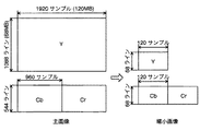
縮小画像生成装置30が生成する縮小画像は、復号化における参照画像に対するエラー補間処理を目的として生成される画像であり、原画像(又は主画像)を水平方向、垂直方向又はその両方で縮小した画像である。例えば、図3に示すように、原画像に対して、輝度信号を水平及び垂直方向のそれぞれに16分の1に縮小し、色差信号を水平及び垂直方向のそれぞれに8分の1に縮小した画像である。縮小処理自体は、サブサンプリングでも、平均化フィルタ処理でもよい。また、原画像の画面内予測処理(画面内予測モード)を16×16画素単位の平均値(DC)に統一することで、予測処理装置14で生成される予測画像の画素値を使用することが可能である。この場合、縮小画像生成装置30は、予測処理装置14から予測画像のマクロブロック毎に1画素のデータを受け取り、縮小画像として出力すれば良い。これにより、縮小画像の輝度信号及び色差信号の1画素が原画像の1マクロブロックに対応する縮小画像が生成される。
The reduced image generated by the reduced
多重化処理装置26には、エントロピー符号化装置24からの符号化映像データ、及び縮小画像生成装置30からの縮小画像データ以外に、図示しないシステム制御装置からのシステムデータが入力する。システムデータは、復号化装置の動作を制御するデータ、例えば、量子化スケール値及び動き補償の動きベクトル等からなる。多重化処理装置26は、これらのデータを多重化し、符号化データとして伝送路又は記録媒体等に出力する。
In addition to the encoded video data from the
MPEG−4 AVCでは、様々なネットワークでの利用が考慮されている。即ち、映像符号化処理を扱うビデオ符号化層(VCL:Video Coding Layer)と伝送・蓄積システムとの間にネットワーク抽象化層(NAL:Network Abstraction Layer)が規定されている。図4に示すように、NALは、NALヘッダとRBSP(Row Byte Sequence Payload)から構成されるNALユニットと呼ばれる単位でパケット化される。NALヘッダによりNALユニットの種類と、参照画像かどうかを識別できるようになっている。NALヘッダに続くRBSPに実際の符号化データが格納される。 In MPEG-4 AVC, utilization in various networks is considered. That is, a network abstraction layer (NAL) is defined between a video coding layer (VCL) that handles video coding processing and a transmission / storage system. As shown in FIG. 4, the NAL is packetized in units called NAL units composed of a NAL header and an RBSP (Row Byte Sequence Payload). The type of NAL unit and whether it is a reference image can be identified by the NAL header. The actual encoded data is stored in the RBSP following the NAL header.
NALユニットの種類又はタイプは、図5に示すように定義されている。シーケンス・パラメータ・セット(SPS:Sequence Parameter Set)は、映像符号化データのシーケンスに関する情報である。ピクチャ・パラメータ・セットPPS(Picture Parameter Set)は、映像符号化データのピクチャに関する情報である。サプリメンタル・エンハンスメント情報(SEI:Supplemental Enhancement Information)は、映像符号化データの復号化には必須ではない付加情報である。主として、映像符号化データ(スライス)、SPS、PPS又はSEI等のNALユニットが使用される。 The type or type of NAL unit is defined as shown in FIG. A sequence parameter set (SPS) is information relating to a sequence of video encoded data. A picture parameter set PPS (Picture Parameter Set) is information relating to a picture of video encoded data. Supplemental enhancement information (SEI) is additional information that is not essential for decoding video-encoded data. Mainly, NAL units such as video encoded data (slice), SPS, PPS, or SEI are used.
これらのNALユニットをピクチャ単位にまとめた単位をアクセス(Access)ユニットと呼ぶ。図6に示すように、アクセスユニットの先頭には、アクセス・ユニット・デリミタ(Access unit delimiter)と呼ばれるNALユニットが位置する。アクセス・ユニット・デリミタは、アクセスユニット内のピクチャタイプを識別する情報を含む。このNALユニットにSPS、PPS及びスライスデータなどの、ピクチャに必要なNALユニット群が続く。 A unit in which these NAL units are grouped into pictures is called an access unit. As shown in FIG. 6, an NAL unit called an access unit delimiter is located at the head of the access unit. The access unit delimiter includes information identifying the picture type in the access unit. This NAL unit is followed by a group of NAL units necessary for the picture, such as SPS, PPS, and slice data.
SEIには、ユーザ定義のシンタクスを使用可能なuser data SEI(ユーザデータSEI)が用意されている。ユーザデータSEIには、user data unregistered SEIと、user data registered by ITU−T Recommendation T.35 SEIが定義されている。ここでは、user data unregistered SEI(ユーザデータ未登録SEI)を利用して、縮小画像を多重化する。 In SEI, user data SEI (user data SEI) that can use user-defined syntax is prepared. The user data SEI includes user data unregistered SEI, user data registered by ITU-T Recommendation T., and so on. 35 SEI is defined. Here, the reduced image is multiplexed using user data unregistered SEI (user data unregistered SEI).
図7は、ユーザデータ未登録SEIのシンタクスを示す。図7におけるシンタクス要素の内、user_data_payload_byte領域に縮小画像を格納できる。ユーザデータ未登録SEIに縮小画像が格納されていることを、uuid_iso_iec_11578領域によりUUIDで識別できるようにしておく。user_data_payload_byte領域に縮小画像を格納するためのエラー補間用データを「esl_picture」と呼び、そのシンタクスの定義を図8に示す。図8で、num_sliceは、格納されている縮小画像のスライス数を示す。top_x、top_yは、主画像のスライスに対応した縮小画像の先頭画素の座標を示し、主画像に対するスライス先頭のマクロブロック座標に対応する。num_pixは縮小画像の画素数を示し、同様に主画像に対するマクロブロック数に対応する。pix_yは、縮小画像の輝度信号Yの画素値であり、pix_cb,pix_crはそれぞれ縮小画像の色差信号Cb,Crの画素値である。このシンタクスからも分かるように、主画像の1画面を複数スライスに分割して符号化した場合においても、任意スライスに対応する縮小画像を格納することが可能となっている。こうすることで、エラー補間用縮小画像のデータ量を抑えたい場合には、重要スライスとする縮小画像のみを格納することも可能である。 FIG. 7 shows the syntax of user data unregistered SEI. Of the syntax elements in FIG. 7, a reduced image can be stored in the user_data_payload_byte area. The fact that the reduced image is stored in the user data unregistered SEI can be identified by the UUID in the uuid_iso_iec_11578 area. Error interpolation data for storing a reduced image in the user_data_payload_byte area is called “esl_picture”, and the definition of the syntax is shown in FIG. In FIG. 8, num_slice indicates the number of slices of the stored reduced image. top_x and top_y indicate the coordinates of the first pixel of the reduced image corresponding to the slice of the main image, and correspond to the macroblock coordinates of the first slice of the main image. num_pix indicates the number of pixels of the reduced image, and similarly corresponds to the number of macroblocks for the main image. pix_y is a pixel value of the luminance signal Y of the reduced image, and pix_cb and pix_cr are pixel values of the color difference signals Cb and Cr of the reduced image, respectively. As can be seen from this syntax, even when one screen of the main image is divided into a plurality of slices and encoded, a reduced image corresponding to an arbitrary slice can be stored. In this way, when it is desired to reduce the data amount of the reduced image for error interpolation, it is also possible to store only the reduced image as the important slice.
例えば、図9に示すように1画面を垂直方向に均等に4分割したスライス構造を持つ画像を想定する。この画像の中心部に位置するスライス1及びスライス2の縮小画像を格納する場合を考えると、num_slice=2となる。スライス1に対応する縮小画像の先頭画素の座標位置は(top_x[0],top_y[0])=(0、17)、画素数は120×17=2040となる。num_pix[0]=2040が格納され、続いてスライス1に対応する縮小画像の画素データが輝度信号Y、色差信号Cb,Crの順で格納される。次に、スライス2に対応する縮小画像の先頭画素の座標位置は(top_x[1],top_y[1])=(0,34)、画素数は同様に2040となる。num_pix[1]=2040が格納され、続いてスライス2に対応する縮小画像の画素データが輝度信号Y,色差信号Cb,Crの順で格納される。尚、図9では、数値は16進数表記で示されている。
For example, as shown in FIG. 9, an image having a slice structure in which one screen is equally divided into four in the vertical direction is assumed. Considering the case where the reduced images of
以上のようにして、ユーザデータ未登録SEIに任意スライスの縮小画像を格納する事が可能となり、これがサクセスユニット内に多重化される。 As described above, a reduced image of an arbitrary slice can be stored in the user data unregistered SEI, and this is multiplexed in the success unit.
こうして縮小画像が多重化された符号化データを受信する映像復号装置側では、esl_pictureを利用したエラー補間処理が可能となる。映像符号化装置と対応する映像復号化装置がネットワークで接続される場合、特に無線伝送では、映像復号化装置側での受信環境により符号化ストリーム内にエラーが発生する場合も少なくない。例えば、図10に示すように、スライス1の3マクロブロック目の符号化データをパースするときに、マクロブロック内のシンタクス要素が規格外の値を示すと、このマクロブロック以降の復号化はほぼ不可能となる。こうした場合、受信したSEIの内、ユーザデータ未登録SEIと、UUIDがesl_pictureを示すSEIとから、esl_pictureシンタクスに従ってスライス1に対応する縮小画像を抽出する。そして、輝度信号Yは、水平・垂直方向共に16倍に拡大し、色差信号Cb,Crは、水平・垂直方向共に8倍に拡大処理する。これにより、復号化できない4マクロブロック目以降のマクロブロックデータを補間することが可能となる。
The video decoding apparatus that receives the encoded data in which the reduced images are multiplexed in this way can perform error interpolation processing using esl_picture. When a video decoding apparatus and a corresponding video decoding apparatus are connected via a network, an error may occur in the encoded stream due to the reception environment on the video decoding apparatus side, particularly in wireless transmission. For example, as shown in FIG. 10, when the encoded data of the third macroblock of
図11及び図12を参照して、こうしたエラーがシーンチェンジ境界のIピクチャで発生した場合のエラー補間処理による再生映像の状態を説明する。図11は、エラーの発生したIピクチャを1つ前のPピクチャで補間する例を示す。図12は、本実施例により、エラーの発生したIピクチャを縮小画像で補間する例を示す。図11に示すように、直前のPピクチャの画素を利用してIピクチャを補間する場合、シーンチェンジ前の画像が、Iピクチャと参照関係にあるフレーム内で影響し、再生画像の乱れが発生する可能性がある。しかし、図12に示すように、本実施例により縮小画像を利用してIピクチャを補間することで、比較的違和感のない再生画像が得られる。 With reference to FIG. 11 and FIG. 12, the state of a reproduced video by error interpolation processing when such an error occurs in an I picture at a scene change boundary will be described. FIG. 11 shows an example in which an errored I picture is interpolated by the previous P picture. FIG. 12 shows an example in which an I picture in which an error has occurred is interpolated with a reduced image according to this embodiment. As shown in FIG. 11, when the I picture is interpolated using the pixels of the immediately preceding P picture, the image before the scene change is affected in the frame having a reference relationship with the I picture, and the reproduction image is disturbed. there's a possibility that. However, as shown in FIG. 12, a reproduced image having a relatively uncomfortable feeling can be obtained by interpolating an I picture using a reduced image according to this embodiment.
以上の説明から容易に理解できるように、本実施例では、シーンチェンジ検出後の、最初の参照画像符号化タイミングで縮小画像を生成し、SEIメッセージとして主画像の符号化データに多重化する。これにより、映像復号化装置側で参照画像にエラーが発生した場合であっても、容易な方法で違和感の少ないエラー補間処理を行うことが可能となる。 As can be easily understood from the above description, in this embodiment, a reduced image is generated at the first reference image encoding timing after the scene change is detected, and is multiplexed as encoded data of the main image as an SEI message. As a result, even when an error occurs in the reference image on the video decoding device side, it is possible to perform error interpolation processing with less discomfort by an easy method.
10:映像入力端子
12:予測方法決定装置
14:予測処理装置
16:シーンチェンジ検出装置
18:メモリ
20:直交変換・量子化装置
22:局所復号化装置
24:エントロピー符号化装置
26:多重化処理装置
28:デブロッキングフィルタ処理装置
30:縮小画像生成装置
10: Video input terminal 12: Prediction method determination device 14: Prediction processing device 16: Scene change detection device 18: Memory 20: Orthogonal transformation / quantization device 22: Local decoding device 24: Entropy coding device 26: Multiplexing processing Device 28: Deblocking filter processing device 30: Reduced image generation device
Claims (5)
前記画面内符号化に係る画面内予測及び前記画面間の予測符号化に係る画面間予測を選択的に行って予測画像を生成する予測処理手段と、
前記映像信号に係る符号化対象画像と前記予測処理手段により生成された前記予測画像との差分を示す残差信号を符号化する符号化手段と、
前記映像信号に係る画像のシーンチェンジを検出するシーンチェンジ検出手段と、
前記シーンチェンジ検出手段によるシーンチェンジの検出後において最初に現れる前記Iピクチャ又は前記Pピクチャから縮小画像を生成する縮小画像生成手段と、
前記シーンチェンジ検出手段によりシーンチェンジが検出されたことに応じて、前記符号化手段から出力される符号化映像データに前記縮小画像を多重化して出力する多重化処理手段
とを具備することを特徴とする映像符号化装置。 Video code that encodes a video signal into encoded data in which an I picture, a P picture, and a B picture are arranged in a predetermined order using intra-picture coding and predictive coding between pictures using a reference picture Device.
Prediction processing means for selectively generating intra-screen prediction related to the intra-screen encoding and inter-screen prediction related to predictive encoding between the screens, and generating a prediction image;
Encoding means for encoding a residual signal indicating a difference between an encoding target image related to the video signal and the prediction image generated by the prediction processing means;
Scene change detection means for detecting a scene change of an image related to the video signal;
A reduced image generation means for generating a reduced image from the I picture or the P-picture appearing on Oite first time after the detection of the scene change by the scene change detecting means,
Multiplex processing means for multiplexing and outputting the reduced image on the encoded video data output from the encoding means in response to a scene change detected by the scene change detection means. A video encoding device.
前記縮小画像生成手段は、前記スライスの単位で前記縮小画像を生成する
ことを特徴とする請求項1に記載の映像符号化装置。 The intra-screen coding and the predictive coding between the screens are determined in units of each slice of a plurality of slices constituting the screen,
The video encoding apparatus according to claim 1, wherein the reduced image generation unit generates the reduced image in units of the slices.
前記符号化映像データの復号化時にエラーが発生した場合に、当該エラーが発生した画像を前記縮小画像によって補間することを特徴とする映像復号化装置。A video decoding apparatus, wherein when an error occurs during decoding of the encoded video data, an image in which the error has occurred is interpolated by the reduced image.
Priority Applications (1)
| Application Number | Priority Date | Filing Date | Title |
|---|---|---|---|
| JP2008141905A JP5147546B2 (en) | 2008-05-30 | 2008-05-30 | Video encoding device and video decoding device |
Applications Claiming Priority (1)
| Application Number | Priority Date | Filing Date | Title |
|---|---|---|---|
| JP2008141905A JP5147546B2 (en) | 2008-05-30 | 2008-05-30 | Video encoding device and video decoding device |
Publications (3)
| Publication Number | Publication Date |
|---|---|
| JP2009290630A JP2009290630A (en) | 2009-12-10 |
| JP2009290630A5 JP2009290630A5 (en) | 2011-07-07 |
| JP5147546B2 true JP5147546B2 (en) | 2013-02-20 |
Family
ID=41459372
Family Applications (1)
| Application Number | Title | Priority Date | Filing Date |
|---|---|---|---|
| JP2008141905A Expired - Fee Related JP5147546B2 (en) | 2008-05-30 | 2008-05-30 | Video encoding device and video decoding device |
Country Status (1)
| Country | Link |
|---|---|
| JP (1) | JP5147546B2 (en) |
Families Citing this family (1)
| Publication number | Priority date | Publication date | Assignee | Title |
|---|---|---|---|---|
| RU2013108079A (en) * | 2010-09-03 | 2014-10-20 | Сони Корпорейшн | DEVICE FOR ENCODING, METHOD FOR ENCODING, DEVICE FOR DECODING AND METHOD FOR DECODING |
Family Cites Families (7)
| Publication number | Priority date | Publication date | Assignee | Title |
|---|---|---|---|---|
| JP3428332B2 (en) * | 1995-12-28 | 2003-07-22 | ソニー株式会社 | Image encoding method and apparatus, and image transmission method |
| JPH1056563A (en) * | 1996-08-09 | 1998-02-24 | Kokusai Electric Co Ltd | Method and equipment for pictorial communication |
| GB2352350B (en) * | 1999-07-19 | 2003-11-05 | Nokia Mobile Phones Ltd | Video coding |
| JP4608953B2 (en) * | 2004-06-07 | 2011-01-12 | ソニー株式会社 | Data recording apparatus, method and program, data reproducing apparatus, method and program, and recording medium |
| EP1732331A1 (en) * | 2005-06-08 | 2006-12-13 | BRITISH TELECOMMUNICATIONS public limited company | Video coding |
| US8369397B2 (en) * | 2005-07-06 | 2013-02-05 | Thomson Licensing | Method and device for coding a video content comprising a sequence of pictures and a logo |
| JP2007110467A (en) * | 2005-10-14 | 2007-04-26 | Mitsubishi Electric Corp | Image recording reproducing device, display method of image data, and image data displaying method of thumbnail image |
-
2008
- 2008-05-30 JP JP2008141905A patent/JP5147546B2/en not_active Expired - Fee Related
Also Published As
| Publication number | Publication date |
|---|---|
| JP2009290630A (en) | 2009-12-10 |
Similar Documents
| Publication | Publication Date | Title |
|---|---|---|
| JP4468800B2 (en) | Random access points in video coding | |
| US9838685B2 (en) | Method and apparatus for efficient slice header processing | |
| KR101538362B1 (en) | Video decoding device, video decoding method, and computer readable storage medium for storing video decoding program | |
| US20140056356A1 (en) | Method and apparatus for efficient signaling of weighted prediction in advanced coding schemes | |
| JP6497423B2 (en) | Video decoding apparatus, video decoding method, and program | |
| JP6345650B2 (en) | Image processing apparatus and image processing method | |
| US10291934B2 (en) | Modified HEVC transform tree syntax | |
| US20160080753A1 (en) | Method and apparatus for processing video signal | |
| CA2491679A1 (en) | Method and system for selecting interpolation filter type in video coding | |
| WO2012096146A1 (en) | Video encoding device, video decoding device, video encoding method, video decoding method, and program | |
| WO2012098845A1 (en) | Image encoding method, image encoding device, image decoding method, and image decoding device | |
| KR20130045783A (en) | Method and apparatus for scalable video coding using intra prediction mode | |
| JP4133346B2 (en) | Intra coding of video data blocks by selection of prediction type | |
| KR20050018948A (en) | Method and system for selecting interpolation filter type in video coding | |
| JP2023553996A (en) | Derivation of offset in inter-component transform coefficient level restoration | |
| JP5147546B2 (en) | Video encoding device and video decoding device | |
| CN116325723A (en) | Cross-component block end-of-block marker coding | |
| JP2024506169A (en) | Joint motion vector differential coding | |
| JP2023543586A (en) | Skip conversion flag encoding | |
| JP5911982B2 (en) | Image decoding method | |
| KR20230015392A (en) | A video encoding/decoding method for signaling a GCI, a computer readable recording medium storing an apparatus and a bitstream | |
| CN117693934A (en) | Luminance and chrominance prediction based on merged chrominance blocks | |
| JP2013017085A (en) | Image encoder and image encoding method | |
| CN116458159A (en) | Skip transform flag coding | |
| CN116998153A (en) | Cross channel prediction based on multiple prediction modes |
Legal Events
| Date | Code | Title | Description |
|---|---|---|---|
| A521 | Written amendment |
Free format text: JAPANESE INTERMEDIATE CODE: A523 Effective date: 20110519 |
|
| A621 | Written request for application examination |
Free format text: JAPANESE INTERMEDIATE CODE: A621 Effective date: 20110519 |
|
| A977 | Report on retrieval |
Free format text: JAPANESE INTERMEDIATE CODE: A971007 Effective date: 20120222 |
|
| A131 | Notification of reasons for refusal |
Free format text: JAPANESE INTERMEDIATE CODE: A131 Effective date: 20120321 |
|
| A521 | Written amendment |
Free format text: JAPANESE INTERMEDIATE CODE: A523 Effective date: 20120514 |
|
| TRDD | Decision of grant or rejection written | ||
| A01 | Written decision to grant a patent or to grant a registration (utility model) |
Free format text: JAPANESE INTERMEDIATE CODE: A01 Effective date: 20121030 |
|
| A61 | First payment of annual fees (during grant procedure) |
Free format text: JAPANESE INTERMEDIATE CODE: A61 Effective date: 20121127 |
|
| R151 | Written notification of patent or utility model registration |
Ref document number: 5147546 Country of ref document: JP Free format text: JAPANESE INTERMEDIATE CODE: R151 |
|
| FPAY | Renewal fee payment (event date is renewal date of database) |
Free format text: PAYMENT UNTIL: 20151207 Year of fee payment: 3 |
|
| RD03 | Notification of appointment of power of attorney |
Free format text: JAPANESE INTERMEDIATE CODE: R3D03 |
|
| LAPS | Cancellation because of no payment of annual fees |