JP5146829B2 - Image forming apparatus - Google Patents
Image forming apparatus Download PDFInfo
- Publication number
- JP5146829B2 JP5146829B2 JP2008265264A JP2008265264A JP5146829B2 JP 5146829 B2 JP5146829 B2 JP 5146829B2 JP 2008265264 A JP2008265264 A JP 2008265264A JP 2008265264 A JP2008265264 A JP 2008265264A JP 5146829 B2 JP5146829 B2 JP 5146829B2
- Authority
- JP
- Japan
- Prior art keywords
- toner
- charging
- transfer
- latent image
- forming apparatus
- Prior art date
- Legal status (The legal status is an assumption and is not a legal conclusion. Google has not performed a legal analysis and makes no representation as to the accuracy of the status listed.)
- Expired - Fee Related
Links
Images


Description
本発明は、複写機、ファクシミリ、プリンタ等の画像形成装置に係り、詳しくは、複数の潜像担持体上に形成したトナー像を重ね合わせてカラー画像を形成する画像形成装置に関するものである。 The present invention relates to an image forming apparatus such as a copying machine, a facsimile machine, or a printer, and more particularly to an image forming apparatus that forms a color image by superimposing toner images formed on a plurality of latent image carriers.
従来、4つの潜像担持体上にイエロー(Y)、シアン(C)、マゼンダ(M)、ブラック(K)のトナー像をそれぞれ形成し、これらを重ね合わせてフルカラー画像を形成する画像形成装置が知られている。この画像形成装置では、高画質化のため形成されるトナー像濃度が一定となるように、各色現像装置に印加する現像バイアスを各色現像装置のバラツキ、耐久性、環境等を考慮して個別に可変制御することが望ましい。 Conventionally, an image forming apparatus that forms yellow (Y), cyan (C), magenta (M), and black (K) toner images on four latent image carriers and forms a full-color image by superimposing them. It has been known. In this image forming apparatus, the developing bias applied to each color developing device is individually considered in consideration of the variation, durability, environment, etc. of each color developing device so that the density of the toner image formed for high image quality is constant. Variable control is desirable.
また、各色現像装置においては、かぶりトナーという問題がある。現像装置では、殆どのトナーは正規帯電極性に帯電する正規帯電トナーであるが、正規帯電極性とは逆極性に帯電してしまう逆帯電トナーも僅かながら発生する。この逆帯電トナーは、本来であれば付着するはずのない潜像担持体の地肌部(帯電部)に付着するいわゆるかぶりという現象を引き起こすものであり、地肌部に付着した逆帯電トナーはかぶりトナーと呼ばれる。このかぶりトナー量は、帯電電位と現像バイアスとのポテンシャル差に大きく依存する。具体的には、帯電電位と現像バイアスのポテンシャル差が大きいほど、逆極性トナーが地肌部に付着してかぶりトナー量は増えてしまう。しかし、かぶりトナー量を少なくするよう、帯電電位と現像バイアスのポテンシャル差を小さくし過ぎると、正規帯電トナーが地肌部に付着して地汚れを引き起こしてしまう。このため、帯電電位と現像バイアスとのポテンシャル差を、かぶりトナー量を少なく、且つ、正規帯電トナーが地肌部に付着しないような最適値に設定にすることが望まれる。すなわち、上記のように可変制御される現像バイアスに対して潜像担持体の帯電電位を可変制御可能な帯電手段が望まれている。しかしながら、帯電電位を可変制御可能な帯電手段は、帯電電位を一定制御する帯電手段に比べコストアップになってしまう。 Further, each color developing device has a problem of fog toner. In the developing device, most of the toner is regular charged toner that is charged to a normal charge polarity, but a small amount of reverse charged toner that is charged to a polarity opposite to the normal charge polarity is also generated. This reversely charged toner causes a phenomenon called “fogging” that adheres to the background portion (charging portion) of the latent image carrier, which should not adhere to the original, and the reversely charged toner attached to the background portion is fogging toner. Called. This amount of fog toner greatly depends on the potential difference between the charging potential and the developing bias. Specifically, the larger the potential difference between the charging potential and the developing bias, the more reverse polarity toner adheres to the background portion, and the amount of fog toner increases. However, if the potential difference between the charging potential and the developing bias is made too small so as to reduce the amount of fog toner, the regular charged toner adheres to the background and causes background staining. For this reason, it is desirable to set the potential difference between the charging potential and the developing bias to an optimal value so that the amount of fog toner is small and regular charged toner does not adhere to the background portion. That is, there is a demand for a charging means that can variably control the charging potential of the latent image carrier with respect to the developing bias that is variably controlled as described above. However, the charging means capable of variably controlling the charging potential is more expensive than the charging means that controls the charging potential at a constant level.
一方、複数の潜像担持体上にトナー像をそれぞれ形成し、これらを重ね合わせてカラー画像を形成する画像形成装置では、コストダウンのために部品の共通化が進められている。その一例として、特許文献1、2には、複数の潜像担持体を帯電させる帯電手段の帯電電源を共通化するものが記載されている。しかしながら、帯電電源を共通化したものでは、複数の潜像担持体の帯電電位を個別に可変制御することはできない。
トナー像を重ね合わせる画像形成装置で、ユーザーの要求する画像品質を調査した結果、ブラック画像は、文字画像が多く鮮鋭性が求められるが、カラー画像は、写真画像が多く鮮鋭性は求められないことがわかった。一般的に、画像の鮮鋭性を上げるためには、トナー粒径を小さくして、より高精細な画像とすることが効果的である。しかしながら、トナー粒径を単純に小さくしただけでは、帯電性を不安定にする微粉率の上昇を招き、上記かぶりトナー量の増大要因となる。 As a result of investigating the image quality requested by the user with an image forming apparatus that superimposes toner images, a black image has many character images and requires sharpness, but a color image has many photographic images and does not require sharpness. I understood it. In general, in order to increase the sharpness of an image, it is effective to reduce the toner particle size to obtain a higher definition image. However, simply reducing the toner particle diameter causes an increase in the fine powder ratio that makes the charging property unstable, and causes an increase in the amount of fog toner.
本発明は、以上の背景に鑑みなされたものであり、その目的とするところは、複数の潜像担持体上に形成したトナー像を重ね合わせる画像形成装置で、高画質化とコストダウンとのバランスのとれた画像形成装置を提供することである。 The present invention has been made in view of the above background, and an object of the present invention is an image forming apparatus that superimposes toner images formed on a plurality of latent image carriers. An object of the present invention is to provide a balanced image forming apparatus.
上記目的を達成するために、請求項1の発明は、自らの表面に潜像を担持する複数の潜像担持体と、該表面をそれぞれ帯電させる複数の帯電手段と、画像情報に基づいて該表面にそれぞれ潜像を書き込む複数の潜像書込手段と、該表面上の潜像にそれぞれトナーを付着させて現像する複数の現像手段と、該表面上に形成されたトナー像を転写体上に転写する転写手段とを備えた画像形成装置において、上記複数の帯電手段として、潜像担持体の帯電電位を一定制御するものと、潜像担持体の帯電電位を可変制御するものとを備え、帯電電位を一定制御する潜像担持体に対応するトナーの体積平均粒径が、帯電電位を可変制御する潜像担持体に対応するトナーの体積平均粒径よりも大きいことを特徴とするものである。
また、請求項2の発明は、自らの表面に潜像を担持する複数の潜像担持体と、該表面をそれぞれ帯電させる複数の帯電手段と、画像情報に基づいて該表面にそれぞれ潜像を書き込む複数の潜像書込手段と、該表面上の潜像にそれぞれトナーを付着させて現像する複数の現像手段と、該表面上に形成されたトナー像を転写体上に転写する転写手段とを備えた画像形成装置において、上記複数の帯電手段として、潜像担持体の帯電電位を一定制御するものと、潜像担持体の帯電電位を可変制御するものとを備え、帯電電位を一定制御する潜像担持体に対応するトナーに含まれる微粉トナーの割合が、帯電電位を可変制御する潜像担持体に対応するトナーに含まれる微粉トナーの割合よりも小さいことを特徴とするものである。
また、請求項3の発明は、請求項1または2の画像形成装置において、ブラックのトナー像を形成する潜像担持体を帯電する帯電手段として帯電電位を可変制御するものを用い、それ以外のトナー像を形成する潜像担持体を帯電する帯電手段として帯電電位を一定制御するものを用いたことを特徴とするものである。
また、請求項4の発明は、請求項3の画像形成装置において、上記帯電電位を一定制御する帯電手段の電源を共通としたことを特徴とするものである。
また、請求項5の発明は、請求項1、2、3または4の何れかの画像形成装置において、上記転写手段による転写工程を経由した後の上記潜像担持体表面に残留しているトナーの量を算出する算出手段を備え、該算出手段は、上記画像情報と、正規極性に帯電した正規帯電トナーに関する転写残予測係数である正規帯電トナー転写残予測係数とに基づいて、該正規帯電トナーの転写残量である正規帯電トナー転写残量を算出し、且つ、少なくとも、正規極性とは逆極性に帯電した逆帯電トナーに関する転写残予測係数である逆帯電トナー転写残予測係数に基づいて、該逆帯電トナーの転写残量である逆帯電トナー転写残量を算出し、該正規帯電トナー転写残量と該逆帯電トナー転写残量との加算結果を、上記転写工程を経由した後の潜像担持体表面に残量しているトナーの量として算出するように構成し、上記帯電電位を一定制御する帯電手段に対応するトナーの逆帯電トナー転写残予測係数と、上記帯電電位を可変制御するトナーの逆帯電トナー転写残予測係数とが異なることを特徴とするものである。
また、請求項6の発明は、請求項5の画像形成装置において、上記帯電電位を一定制御する帯電手段に対応するトナーの逆帯電トナー転写残予測係数が、上記帯電電位を可変制御する帯電手段に対応するトナーの逆帯電トナー転写残予測係数より大きいことを特徴とするものである。
また、請求項7の発明は、請求項5または6の画像形成装置において、上記帯電電位を一定制御する帯電手段に対応するトナーの逆帯電転写残量の算出値の経時における変化幅が、上記帯電電位を可変制御する帯電手段に対応するトナーの逆帯電転写残量の算出値の経時における変化幅よりも大きくなるように、上記逆帯電トナー転写残予測係数を経時で変化させることを特徴とするものである。
また、請求項8の発明は、請求項5、6または7の何れかの画像形成装置において、上記帯電電位を一定制御する帯電手段に対応するトナーの逆帯電転写残量の算出値の環境変化時における変化幅が、上記帯電電位を可変制御する帯電手段に対応するトナーの逆帯電転写残量の算出値の環境変化時における変化幅よりも大きくなるように、上記逆帯電トナー転写残予測係数を環境変化時で変化させることを特徴とするものである。
また、請求項9の発明は、請求項1、2、3、4、5、6、7または8の何れかの画像形成装置において、ブラック、イエロー、シアン、マゼンダの各色のトナー像をそれぞれ形成される潜像担持体を転写体に対して並列に配置し、イエロー、シアン、マゼンダの潜像担持体を該転写体から離間して停止させ、ブラックの潜像担持体のみでトナー像を形成するモノクロモードを有しており、ブラックの潜像担持体を帯電する帯電手段はブラック用の帯電電源を用いて帯電電位を可変制御するものであり、イエロー、シアン、マゼンダのトナー像を形成する潜像担持体を帯電する各帯電手段は共通の帯電電源を用いて帯電電位を一定制御するものであることを特徴とするものである。
In order to achieve the above object, the invention of
According to a second aspect of the present invention, a plurality of latent image carriers that carry a latent image on their surface, a plurality of charging means that respectively charge the surface, and a latent image on the surface based on image information. A plurality of latent image writing means for writing; a plurality of developing means for developing toner by attaching the toner to the latent image on the surface; and a transfer means for transferring the toner image formed on the surface onto the transfer member; In the image forming apparatus, the plurality of charging means include a unit that controls the charging potential of the latent image carrier and a unit that variably controls the charging potential of the latent image carrier, and controls the charging potential constant. The ratio of the fine powder toner contained in the toner corresponding to the latent image carrier is smaller than the percentage of the fine powder toner contained in the toner corresponding to the latent image carrier whose charge potential is variably controlled. .
According to a third aspect of the present invention, in the image forming apparatus of the first or second aspect, the charging means for variably controlling the charging potential is used as a charging means for charging the latent image carrier that forms the black toner image. As a charging means for charging a latent image carrier that forms a toner image, a means for controlling the charging potential to a constant value is used.
According to a fourth aspect of the present invention, in the image forming apparatus of the third aspect, a common power source is used for the charging means for controlling the charging potential at a constant level.
According to a fifth aspect of the present invention, in the image forming apparatus according to any one of the first, second, third, and fourth aspects, the toner remaining on the surface of the latent image carrier after passing through the transfer step by the transfer unit. And calculating means for calculating the amount of the normal charge based on the image information and a normal charge toner transfer residual prediction coefficient that is a transfer residual prediction coefficient relating to the normal charge toner charged to the normal polarity. Based on a reversely charged toner transfer residual prediction coefficient that is a transfer residual prediction coefficient for a reversely charged toner that is charged with a polarity opposite to that of the normal polarity, and that calculates a normally charged toner transfer residual amount that is a toner transfer remaining amount The reverse charge toner transfer remaining amount that is the transfer amount of the reverse charge toner is calculated, and the addition result of the normal charge toner transfer remaining amount and the reverse charge toner transfer remaining amount is obtained after passing through the transfer step. Latent image carrier It is configured to calculate the amount of toner remaining on the surface, and the reversely charged toner transfer residual prediction coefficient of the toner corresponding to the charging means for controlling the charging potential to be constant, and the toner for variably controlling the charging potential. The reversely charged toner transfer residual prediction coefficient is different.
According to a sixth aspect of the present invention, in the image forming apparatus according to the fifth aspect, the charging means for variably controlling the charging potential is a reversely charged toner transfer residual prediction coefficient of toner corresponding to the charging means for controlling the charging potential at a constant level. It is characterized by being larger than the reversely charged toner transfer residual prediction coefficient of the toner corresponding to.
According to a seventh aspect of the present invention, in the image forming apparatus according to the fifth or sixth aspect, a change width with time of a calculated value of the reverse charge transfer remaining amount of the toner corresponding to the charging unit that controls the charging potential to be constant is The reverse charge toner transfer residual prediction coefficient is changed over time so that the calculated value of the reverse charge transfer remaining amount of toner corresponding to the charging means for variably controlling the charging potential is larger than the change width with time. To do.
According to an eighth aspect of the present invention, in the image forming apparatus according to any one of the fifth, sixth, and seventh aspects, an environmental change in a calculated value of a reverse charge transfer remaining amount of toner corresponding to a charging unit that controls the charging potential at a constant level. The reversely charged toner transfer residual prediction coefficient so that the change width at the time becomes larger than the change width at the time of environmental change of the calculated value of the reverse charge transfer remaining amount of the toner corresponding to the charging means for variably controlling the charging potential. It is characterized by changing the time when the environment changes.
According to a ninth aspect of the present invention, in the image forming apparatus according to any one of the first, second, third, fourth, fifth, sixth, seventh, or eighth aspects, a toner image of each color of black, yellow, cyan, and magenta is formed. The latent image carrier to be transferred is arranged in parallel with the transfer member, and the yellow, cyan, and magenta latent image carriers are moved away from the transfer member and stopped to form a toner image only with the black latent image carrier. The charging means for charging the black latent image carrier is a variably controlled charging potential using a black charging power source, and forms yellow, cyan, and magenta toner images. Each charging means for charging the latent image carrier is characterized in that the charging potential is controlled to be constant by using a common charging power source.
請求項1に記載の発明特許事項の全てを備える発明においては、複数の現像手段のうち、鮮鋭性を向上させるため体積平均粒径の小さいトナーを用いるものでは小粒径化に伴う微粉率の上昇により逆帯電トナーが発生しやすい。このため、対応する潜像担持体の帯電手段として帯電電位を可変制御するものを用いて、かぶりトナー量を少なくするように帯電電位と現像バイアスとのポテンシャル差を最適値に設定する。一方、複数の現像手段のうち、鮮鋭性をあまり求められないため体積平均粒径を大きいトナーを用いるものでは、粒径の小さいトナーに比べ逆帯電トナーが発生し難い。このため、対応する潜像担持体の帯電手段として帯電電位を一定制御するものを用いてもかぶりトナー量が多くなる虞は少ない。このように高画質化を図りつつ、複数の帯電手段のうち一部を帯電電位を可変制御するものを用い、それ以外は帯電電位を一定制御するものを用いることにより、画像形成装置のコストダウンを図ることができる。
また、請求項2に記載の発明特許事項の全てを備える発明においては、複数の現像手段のうち、鮮鋭性を向上させるため微粉トナーの割合が大きいトナーを用いるものでは逆帯電トナーが発生しやすい。このため、対応する潜像担持体の帯電手段として帯電電位を可変制御するものを用いて、かぶりトナー量を少なくするように帯電電位と現像バイアスとのポテンシャル差を最適値に設定する。一方、複数の現像手段のうち、鮮鋭性をあまり求められないため微粉トナーの割合が比較的小さいトナーを用いるものでは、微粉トナーの割合が大きいトナーに比べ逆帯電トナーが発生し難い。このため、対応する潜像担持体の帯電手段として帯電電位を一定制御するものを用いてもかぶりトナー量が多くなる虞は少ない。このように高画質化を図りつつ、複数の帯電手段のうち一部を帯電電位を可変制御するものを用い、それ以外は帯電電位を一定制御するものを用いることにより、画像形成装置のコストダウンを図ることができる。
In the invention having all of the patent matters of the invention described in
In the invention including all of the invention patent matters described in
以上、本発明によれば、複数の潜像担持体上に形成したトナー像を重ね合わせる画像形成装置で、高画質化とコストダウンとのバランスのとることができるという優れた効果がある。 As described above, according to the present invention, an image forming apparatus that superimposes toner images formed on a plurality of latent image carriers has an excellent effect of achieving a balance between high image quality and cost reduction.
以下、本発明を適用した画像形成装置の第一の実施形態として、電子写真方式のカラーレーザープリンタ(以下、単にプリンタという)について説明する。
まず、第一の実施形態に係るプリンタの基本的な構成について説明する。図1は、第一の実施形態に係るプリンタを示す概略構成図である。このプリンタは、イエロー(Y),マゼンダ(M),シアン(C),ブラック(K)の各色のトナー像を形成するための4つのプロセスユニット1Y,M,C,Kを備えている。また、光書込ユニット50、給紙カセット51、給紙路53、レジストローラ対54、転写ユニット60、定着装置80、排紙ローラ対55、スタック部56等も備えている。なお、各符号の添字Y,M,C,Kは、それぞれイエロー、マゼンダ、シアン、ブラック用の部材であることを示す。
Hereinafter, an electrophotographic color laser printer (hereinafter simply referred to as a printer) will be described as a first embodiment of an image forming apparatus to which the present invention is applied.
First, the basic configuration of the printer according to the first embodiment will be described. FIG. 1 is a schematic configuration diagram illustrating the printer according to the first embodiment. The printer includes four
潜像書込手段としての光書込ユニット50は、Y,M,C,Kの各色に対応する図示しない4つのレーザーダイオードからなる光源、正六面体のポリゴンミラー、これを回転駆動するためのポリゴンモータ、fθレンズ、レンズ、反射ミラー等を有している。レーザーダイオードから射出されたレーザー光Lは、ポリゴンミラーによって偏向せしめられながら、後述する4つの感光体のうちの何れかに到達する。これにより、4つの感光体の表面がそれぞれ暗中にて光走査される。
The
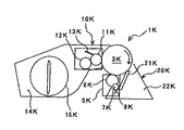
図2は、4つのプロセスユニット1Y,M,C,Kのうち、K用のプロセスユニット1Kを示す拡大構成図である。同図において、プロセスユニット1Kは、感光体3K、これの回りに配設された帯電装置5K、現像装置10K、ドラムクリーニング装置20Kなどを有している。そして、それらを1つのユニットとして共通のケーシング(保持体)に保持してプリンタ本体に対して一体的に着脱するようになっている。
FIG. 2 is an enlarged configuration diagram showing the
感光体3Kは、アルミ等からなるドラム状の素管の周面に有機感光層が被覆されたものであり、図示しない駆動手段によって所定の線速で図中時計回り方向に回転駆動せしめられる。
The
帯電装置5Kは、感光体3Kに接触又は近接しながら回転駆動される帯電ローラ6K、これに接触しながら回転する帯電クリーニングローラ7K、これに接触する帯電クリーニングブレード8K等を有している。そして、後述する電源によって帯電バイアスが印加される帯電ローラ6Kと、感光体3Kとの間に放電を生じせしめることで、感光体3Kの表面をKトナーの正規帯電極性と同極であるマイナス極性に一様帯電せしめる。帯電ローラ6Kには、感光体3Kとの対向位置でKトナーが付着することがあるが、図示しない電源によってクリーニングバイアスが印加される帯電クリーニングローラ7Kに転移する。そして、帯電クリーニングブレード8Kによって帯電クリーニングローラ7Kから掻き取られて、帯電装置5Kのケーシングに設けられたトナー収容部に貯留される。感光体3Kから帯電ローラ6Kに転移するKトナーの量はごく僅かであるため、プロセスユニット1Kの寿命が到来する前に、帯電装置5Kのトナー収容部が満杯になることはない。
The
なお、本プリンタでは、帯電装置5Kとして、帯電ローラ6Kを用いる方式のものを採用しているが、帯電ブラシを用いる方式のものや、スコロトロン方式のものを採用してもよい。
In this printer, the
帯電装置5Kによって一様に帯電せしめられた感光体3Kの表面には、上述した光書込ユニット50による光走査でK用の静電潜像が形成される。そして、静電潜像は現像装置10KによってKトナー像に現像される。
An electrostatic latent image for K is formed on the surface of the
現像装置10Kは、ケーシングの側面に設けられた開口から自らの周面の一部を露出させながら回転駆動される現像ローラ11Kを有している。また、この現像ローラ11Kに当接しながら回転するトナー供給ローラ12K、薄層化ブレード13K、トナー収容部14K、撹拌部材15Kなども有している。
The developing
トナー収容部14K内には、図示しないKトナーが収容されている。このKトナーは、トナー収容部14K内に配設された撹拌部材15Kによって撹拌される。この撹拌部材15Kにより、後述するトナー供給ローラ12Kに向けて送られる。
K toner (not shown) is stored in the
トナー供給ローラ12Kは、芯金と、これの表面に被覆された発泡ウレタン等の発泡体からなるトナー担持層とを有しており、図示しない駆動手段によって現像ローラ11Kとはカウンター方向に回転駆動される。そして、撹拌部材15Kから送られてきたKトナーをトナー担持層の発泡セル内に取り込んだ後、後述する現像ローラ11Kとの当接位置で現像ローラ11Kの表面に供給する。
The
現像ローラ11Kは、芯金と、これの表面に被覆された弾性層とを有しており、図示しない軸受けによって回転自在に支持されながら、図示しない駆動手段によって図中反時計回り方向に回転駆動される。そして、トナー供給ローラ12Kから供給されたKトナーを弾性層の表面に担持する。これによって現像ローラ11Kの表面に形成されたKトナー層は、現像ローラ11Kの回転に伴って、薄層化ブレード13Kと現像ローラ11Kとの当接部に進入する。そして、薄層化ブレード13Kによって薄層化せしめられたり、Kトナー粒子の摩擦帯電が促されたりした後、現像ローラ11Kと感光体3Kとが当接している現像領域に送られる。
The developing
現像ローラ11Kには、図示しない電源によって現像バイアスが印加されている。この現像バイアスは、マイナス極性の直流電圧、あるいは、マイナス極性の直流電圧に交流電圧が重畳された重畳電圧であるが、何れにしても直流電圧は、感光体3Kのマイナス極性の静電潜像よりも大きく、且つ、感光体3Kの地肌部(一様帯電部)よりも小さい値になっている。現像領域では、マイナス極性に帯電しているKトナーが感光体3Kの静電潜像に転移する。これにより、静電潜像がKトナー像に現像される。
A developing bias is applied to the developing
このようにして現像されたKトナー像は、感光体3Kの回転に伴って、感光体3Kと後述する中間転写ベルト61とが当接する1次転写ニップに送られて、ここで中間転写ベルト61のおもて面に1次転写される。
The K toner image developed in this manner is sent to the primary transfer nip where the
なお、本プリンタでは、現像剤として、トナーを主成分とする1成分現像剤を用いる一成分現像方式の現像装置10Kを採用しているが、トナーと磁性キャリアとを主成分とする2成分現像剤を用いる2成分現像方式の現像装置を採用してもよい。
The printer employs a one-component developing
1次転写ニップを通過した感光体3Kの表面には、転写体たる中間転写ベルト61に転写されなかった転写残トナーが付着している。この転写残トナーは、ドラムクリーニング装置20Kによって感光体3Kから除去される。
Untransferred toner that has not been transferred to the
ドラムクリーニング装置20Kは、1次転写ニップを通過した後、上述した帯電装置5Kとの対向位置に進入する前の感光体3K表面に当接しながら感光体3Kから転写残トナーを掻き取る除去手段としてのクリーニングブレード21Kを有している。また、掻き取り後の転写残トナーを収容する廃トナー収容手段としての廃トナー収容部22Kも有している。
The
感光体3Kの表面上の転写残トナーは、ドラムクリーニング装置20Kのクリーニングブレード21Kによって感光体3Kから掻き取られた後、廃トナー収容部22K内に収容される。なお、プロセスユニット1Kは、その内部の各機器の何れかが寿命に到達した時点で新品に交換されるが、製品毎の耐久性のバラツキや、頻出プリント品質などによっては、寿命到来前に廃トナー収容部22Kが満杯エラーとなることがある。このような場合にも、寿命として新たなユニットに交換される。
The transfer residual toner on the surface of the
ドラムクリーニング装置20Kによって転写残トナーがクリーニングされた感光体3Kの表面は、図示しない除電ランプによって除電処理が施された後、帯電装置5Kによって一様帯電せしめられる。
The surface of the
図2を用いて、図1に示した4つのプロセスユニット1Y,M,C,Kのうち、K用のユニットについて説明してきたが、他色用のプロセスユニット1M,C,Kも同様の構成になっているので説明を省略する。
Of the four
先に示した図1において、各色のプロセスユニット1Y,M,C,Kの図中下方には、転写ユニット60が配設されている。この転写ユニット60は、無端状の中間転写61を、複数の張架ローラによって張架しながら、図中反時計回り方向に無端移動せしめる。この複数の張架ローラとは、具体的には、駆動ローラ62、2次転写ローラ63、クリーニングバックアップローラ64、4つの1次転写ローラ65Y,M,C,Kである。転写ユニット60は、これらの他、各ローラを両端部でそれぞれ回転自在に支持する図示しないブラケットや、ベルトループ外側に配設された2次転写ニップローラ66等も有している。
In FIG. 1 described above, a
中間転写ベルト61の材料としては、ポリフッ化ビニリデン、ポリイミド、ポリカーボネート、ポリエチレンテレフタレート等の樹脂材料を例示することができる。これらの樹脂材料をシームレスベルトに成形して用いる。但し、樹脂材料をそのままの状態で使用するのではなく、カーボンブラック等の導電性材料を分散せしめて電気抵抗を調整することが望ましい。また、これらの樹脂材料をシームレスベルト状に成型したものをベルト基体として、それにスプレーやディッピング等の方法によって表面層などを積層してもよい。
Examples of the material of the
駆動ローラ62、2次転写ローラ63、クリーニングバックアップローラ64、4つの1次転写ローラ65Y,M,C,Kは、何れも中間転写ベルト61の裏面(ループ内周面)に接触している。
The drive roller 62, the
4つの1次転写ローラ65Y,M,C,Kは、金属製の芯金にスポンジやゴムの弾性体が被覆されたローラであり、Y,M,C,K用の感光体3Y,M,C,Kに向けて押圧されて、感光体との間に中間転写ベルト61を挟み込むようになっている。これにより、4つの感光体3Y,M,C,Kと中間転写ベルト61のおもて面とがベルト移動方向において所定の長さで接触するY,M,C,K用の4つの1次転写ニップが形成されている。
The four
4つの1次転写ローラ65Y,M,C,Kの芯金には、それぞれ図示しない転写バイアス電源によって定電流制御される転写バイアスが印加されている。これにより、4つの1次転写ローラ65Y,M,C,Kを介して中間転写ベルト61の裏面に転写電荷が付与され、各1次転写ニップにおいて中間転写ベルト61と感光体3Y,M,C,Kとの間に1次転写電界が形成される。この1次転写電界により、感光体3Y,M,C,K上のY,M,C,Kトナー像が、中間転写ベルト61のおもて面に重ね合わせて転写される。そして、これにより、中間転写ベルト61のおもて面に4色重ね合わせトナー像が形成される。
A transfer bias controlled at a constant current by a transfer bias power source (not shown) is applied to the cores of the four
なお、本プリンタにおいては、転写電界を形成するための手段として1次転写ローラ65Y,M,C,Kや後述の2次転写ローラ63を設けているが、ローラに代えて、ブラシやブレード等のものを用いてもよい。また、転写チャージャーなどを用いてもよい。
In this printer,
中間転写ベルト61の周方向における全領域のうち、ベルトループ内側に配設された2次転写ローラ63に対する駆け回し箇所に対しては、ベルトループ外側に配設された2次転写ニップローラ66がベルトおもて面側から当接している。これにより、中間転写ベルト61のおもて面と、2次転写ニップローラ66とが当接する2次転写ニップが形成されている。
Of the entire area in the circumferential direction of the
ベルトループ内側に配設された2次転写ローラ63には、図示しない電源によって定電流制御されるマイナス極性の2次転写バイアスが印加されている。これに対し、ベルトループ外側に配設された2次転写ニップローラ66は接地されている。そして、2次転写ローラ63と2次転写ニップローラ66との間には、マイナス極性のトナーからなる4色重ね合わせトナー像を、2次転写ローラ63側から2次転写ニップローラ66側に向けて静電移動させる2次転写電界が形成されている。
The
中間転写ベルト61のおもて面に形成された4色重ね合わせトナー像は、ベルトの無端移動に伴って、2次転写ニップに進入する。
The four-color superimposed toner image formed on the front surface of the
プリンタ本体の下部には、給紙カセット51が配設されている。この給紙カセット51は、記録紙Pを複数枚重ねた紙束の状態で収容しており、一番上の記録紙Pに給紙コロ51aを押し当てている。そして、所定のタイミングで給紙コロ51aを回転させて、記録紙Pを給紙路53に送り出す。
A paper feed cassette 51 is disposed at the bottom of the printer body. The paper feed cassette 51 stores a plurality of recording papers P in a bundle of sheets, and presses the paper feeding roller 51a against the uppermost recording paper P. Then, the sheet feeding roller 51 a is rotated at a predetermined timing, and the recording sheet P is sent out to the
給紙路53の途中には、レジストローラ対54が配設されており、給紙カセット51から送られてくる記録紙Pをローラ間に挟み込むために両ローラを回転駆動させているが、記録紙Pの先端を挟み込むとすぐに両ローラの回転駆動を停止させる。そして、記録紙Pを後述する2次転写ニップで中間転写ベルト61上の4色重ね合わせトナー像に同期させ得るタイミングを見計らって、記録紙Pを2次転写ニップに向けて送り出す。
In the middle of the
2次転写ニップに挟み込まれた記録紙Pには、上述した2次転写電界やニップ圧の作用により、中間転写ベルト61上の4色重ね合わせトナー像が一括2次転写される。そして、記録紙Pの白色と相まってフルカラートナー像になる。
On the recording paper P sandwiched in the secondary transfer nip, the four-color superimposed toner image on the
4つの1次転写ローラ65Y,M,C,Kのうち、Y,M,C用の3つは、それぞれ、図示しない軸受けを介して図示しない揺動ブラケットに支持されている。この揺動ブラケットは、図示しない回動軸を中心に揺動可能になっている。この揺動により、3つの1次転写ローラ65Y,M,Cが移動して、中間転写ベルト61の張架姿勢が、ベルトをK用の感光体3Kだけに当接させる姿勢になったり、4つの感光体3Y,M,C,Kのそれぞれに当接させる姿勢になったりする。
Of the four
本プリンタは、フルカラー画像をプリントアウトする際には、次のようなプリント動作を行う。即ち、外部の図示しないパーソナルコンピュータ等から送られてくるフルカラー画像データ(画像情報)を受信すると、上述した揺動ブラケット(不図示)の駆動により、中間転写ベルト61に対して4つの感光体3Y,M,C,Kの全てを当接させる姿勢をとらせながら、これら感光体をそれぞれ図中時計回り方向に回転駆動させる。そして、各感光体3Y,M,C,KにY,M,C,Kトナー像を形成し、中間転写ベルト61のおもて面にそれらの重ね合わせによる4色重ね合わせトナー像を形成する。次いで、2次転写ニップで4色重ね合わせトナー像を記録紙Pに一括2次転写した後、記録紙Pを定着装置80に送る。
This printer performs the following printing operation when printing out a full-color image. That is, when full color image data (image information) sent from an external personal computer (not shown) or the like is received, the four photosensitive members 3Y with respect to the
定着装置80は、ハロゲンランプ等の発熱源を内包する定着ローラ81と、加圧ローラ82との当接によって定着ニップを形成しており、2次転写ニップから送られてきた記録紙Pを定着ニップ内に挟み込む。そして、ニップ内での加熱や加圧の作用により、フルカラートナー像を記録紙P面に定着せしめる。このようにして定着処理が施された記録紙Pは、排紙ローラ対55を経由した後、プリンタの筺体内から排出されて筺体上面のスタック部にスタックされる。
The fixing
複数の記録紙Pに連続して画像を形成する連続プリントモードでは、これまで説明してきたプロセスが繰り返されることで、複数の記録紙Pのそれぞれにフルカラー画像が連続的にプリントされていく。 In the continuous print mode in which images are continuously formed on a plurality of recording papers P, a full color image is continuously printed on each of the plurality of recording papers P by repeating the processes described so far.
また、本プリンタで、ユーザーの使用状況を調査した結果、ブラック画像のみを形成するモノクロでの使用割合が多いこともわかった。そこで、本プリンタは、モノクロ画像をプリントアウトするモノクロモードを設け、モノクロモードの際には、中間転写ベルト61に対して感光体3Y,M,Cを離間させて停止し、感光体3Kのみでプリンタ動作をおこなうことにより、Y,M,Cの無駄な使用を避けている。即ち、外部の図示しないパーソナルコンピュータ等から送られてくるモノクロ画像データ(画像情報)を受信すると、上述した揺動ブラケット(不図示)の駆動により、中間転写ベルト61に対して、4つの感光体3Y,M,C,Kのうち、K用の感光体3Kだけを当接させる姿勢をとらせながら、K用の感光体3Kだけを図中時計回り方向に回転駆動させる。すなわち、モノクロ画像の場合には、Y,M,C用の転写ニップでの1次転写が行われないので、それらの転写ニップを形成しないようにするのである。これにより、中間転写ベルト61、K用以外のプロセスユニット1Y,M,C(とりわけ感光体)、その駆動系などに余計な負荷をかけることなく、モノクロ画像をプリントアウトすることができる。
In addition, as a result of investigating the usage situation of users with this printer, it was found that the usage ratio in monochrome, which forms only black images, is large. Therefore, this printer is provided with a monochrome mode for printing out a monochrome image. In the monochrome mode, the photosensitive members 3Y, M, and C are separated from the
K用の感光体3Kや中間転写ベルト61の駆動を開始したら、K用のプロセスユニット1Kにて感光体3K上にKトナー像を形成する。そして、それを中間転写ベルト61上に単独で1次転写しながら、所定のタイミングで記録紙Pをレジストローラ対54から送り出す。次いで、中間転写ベルト61上のKトナー像を2次転写ニップで記録紙Pに2次転写した後、フルカラー画像の形成のときと同じようにして、定着処理等を施す。
When driving of the
以上の基本的な構成を備える本プリンタでは、転写ユニット60が、現像によって感光体3Y,M,C,Kの表面上に得られたY,M,C,Kトナー像を転写体たる中間転写ベルト61に転写する転写手段として機能している。なお、感光体から、中間転写ベルト61を介して記録紙Pにトナー像を転写する方式について説明したが、各感光体から転写体たる記録紙Pに直接的にトナー像を重ね合わせ転写する方式を採用してもよい。
In this printer having the above basic configuration, the
次に、本プリンタの特徴的な構成について説明する。図3は、本プリンタのプロセスユニット1Y,M,C,Kの帯電装置5Y,M,C,Kの電源構成の説明図である。上述のように、各プロセスユニット1Y,M,C,Kは、感光体3Y,M,C,Kを帯電させるための帯電装置5Y,M,C,Kを備えている。本プリンタでは、K用の帯電装置5Kに帯電バイアスを印加するための帯電電源30と、Y,M,C用の帯電装置5Y,M,Cに帯電バイアスを印加するための共通帯電電源31との二つの帯電電源を備える。このように、帯電装置5Y,M,Cの電源を共通化することにより、コストダウンが図れる。一方、図10は、従来の帯電装置5Y,M,C,Kの電源構成の説明図である。図10に示すように、コストダウンのために帯電電源を1つとした場合は、モノクロモード実行時に停止した帯電装置5Y,M,Cにも電圧が印加されることになる。しかし、本プリンタのように電源を2つとすることにより、モノクロモードでK用の帯電装置5Kにのみ電圧を印加することができる。これは、1つの電源でスイッチング回路などを設けてK用の帯電装置5Kにのみ電圧を印加するものに比べ、設計が複雑になりコストアップとなるという不具合を避け、最も安くシンプルな構成である。
Next, a characteristic configuration of the printer will be described. FIG. 3 is an explanatory diagram of the power supply configuration of the
また、本プリンタでは、K用の帯電装置5Kには帯電電位を可変制御するよう電圧を可変供給可能な帯電電源30から帯電バイアスを供給する。また、Y,M,C用の帯電装置5Y,M,Cには帯電電位を一定制御するよう一定の電圧を供給可能な帯電電源31から帯電バイアスを供給する。
Further, in this printer, a charging bias is supplied to the
さらに、本プリンタでは、K用の現像装置10Kでは、体積平均粒径約6〜8.5μmとなる比較的的小粒径のトナーを用いる。これは、経時での変動幅も含む値であり、例えば、初期の体積平均粒径が6μmで、経時での体積平均粒径が8.5μmとなるようなものである。一方、Y,M,C用の現像装置10Y,M,Cには、体積平均粒径約7.5〜10μmとなる、K用よりも粒径の大きいトナーを用いる。これも、経時での変動幅も含む値である。これは、K画像は、文字画像が多く鮮鋭性が求められるため、トナー粒径を小さくしてより高精細な画像を得て高画質化を図るものである。一方、カラー画像は、写真画像が多く鮮鋭性は求められないため、トナー粒径をK用ほど小さくしなくとも十分に高画質な画像が得られる。
Further, in the printer, the developing
図4に、本プリンタに用いられるトナーの体積平均粒径とトナー微粉率との関係を示す。ここで、トナー微粉率は、4μm以下のトナーの個数割合である。図4に示すように、トナーの体積平均粒径を小さくしていくと、トナー帯電性を不安定にさせると推測できるトナー微粉率が高まる。図5に、帯電電位と現像バイアスのポテンシャル差と白画像部トナー付着量(地肌部に付着するかぶりトナー量)との関係をトナー平均粒径毎に示す。図5に示すように、平均粒径が小さいトナーを使用すると地肌部へのかぶりトナー量が増大し、帯電電位と現像バイアスのポテンシャル差が大きくなると、より顕著にかぶりトナー量が増大する。 FIG. 4 shows the relationship between the volume average particle diameter of the toner used in the printer and the toner fine powder ratio. Here, the toner fine powder ratio is the number ratio of toner of 4 μm or less. As shown in FIG. 4, as the volume average particle size of the toner is decreased, the toner fine powder rate that can be estimated to destabilize the toner chargeability increases. FIG. 5 shows the relationship between the potential difference between the charging potential and the developing bias and the white image portion toner adhesion amount (fogging toner amount adhering to the background portion) for each toner average particle diameter. As shown in FIG. 5, when toner having a small average particle diameter is used, the amount of fog toner on the background increases, and when the potential difference between the charging potential and the development bias increases, the amount of fog toner increases more remarkably.
このことから、小粒径のトナーを用いるKに関しては、帯電電位を可変制御することにより、帯電電位と現像バイアスのポテンシャル差を適正値になるようにして、かぶりトナー量の増大を抑制する。具体的には、K用の帯電装置5Kには、濃度調整後に決定される現像バイアスの値に基づき、現像バイアス値に対して−150Vの帯電電位になるよう可変制御する。例えば、現像バイアスが−200Vであれば、K用の感光体1Kの帯電電位を−350Vとなるよう帯電電源30から帯電バイアスを供給する。一方、これよりも粒径の大きいトナーを用いるY,M,Cに関しては、帯電電位を一定制御する。具体的には、Y,M,C用の感光体1Y,M,C用の帯電電位を−500Vとなるよう共通帯電電源31ら帯電バイアスを供給する。なお、Y,M,Cに関しては、トナー微粉率が低く、帯電電位と現像バイアスのポテンシャル差に依らずかぶりトナー量が少ないので、現像バイアスが変化させた場合でも、帯電電位を一定として構わない。このように、高画質化を図りつつ、複数の帯電装置のうちK用は帯電電位を可変制御する帯電電源30を用い、それ以外のY,M,C用は帯電電位を一定制御する共通帯電電源31を用いることにより、コストダウンを図ることができる。なお、本プリンタで現像バイアスの可変幅は、K,Y,M,C用いずれも−100〜−350Vとした。
Therefore, for K using a toner having a small particle diameter, the charging potential is variably controlled so that the potential difference between the charging potential and the developing bias becomes an appropriate value, thereby suppressing the increase in the amount of fog toner. Specifically, the
さらに、かぶりトナー量に直接的に関係する特性値である微粉トナーの割合に基づき帯電電位を可変制御することで、より確実に微粉トナーの割合が大きい色に対してかぶりトナー量の低減効果を得ることができる。例えば、K用の現像装置10Kでは、4μm以下の個数割合である微粉率が15〜30%のトナーを用いる。一方、Y,M,C用の現像装置10Y,M,Cには、微粉率が5〜20%のトナーを用いる。ここで、図6に、帯電電位と現像バイアスのポテンシャル差と白画像部トナー付着量(地肌部に付着するかぶりトナー量)との関係をトナー微粉率毎に示す。図6に示すように、微粉率が増えると地肌部へのかぶりトナー量は増大し、帯電電位と現像バイアスのポテンシャル差が大きくなると、より顕著にかぶりトナー量が増大する。
Furthermore, the charge potential is variably controlled based on the proportion of fine toner, which is a characteristic value directly related to the amount of fog toner, so that the effect of reducing the amount of fog toner can be more reliably applied to colors with a large proportion of fine toner. Can be obtained. For example, in the developing
そこで、微粉率の大きいトナーを用いるKに関しては、帯電電位を可変制御することにより、帯電電位と現像バイアスのポテンシャル差を適正値になるようにして、かぶりトナー量の増大を抑制する。具体的には、K用の帯電装置5Kには、濃度調整後に決定される現像バイアスの値に基づき、現像バイアス値に対して−150Vの帯電電位になるよう可変制御するため、帯電電源30から可変帯電バイアスを供給する。一方、比較的微粉率の大きいトナーを用いるY,M,Cに関しては、帯電電位を−500Vになるよう一定制御する。具体的には、Y,M,C用の感光体1Y,M,C用の帯電電位を−500Vとなるよう一定制御するため、帯電電源31から一定帯電バイアスを供給する。このように、高画質化を図りつつ、複数の帯電装置のうちK用は帯電電位を可変制御する帯電電源30を用い、それ以外のY,M,C用は帯電電位を一定制御する共通帯電電源31を用いることにより、コストダウンを図ることができる。
Therefore, for K using toner with a high fine powder ratio, the charging potential is variably controlled so that the potential difference between the charging potential and the developing bias becomes an appropriate value, thereby suppressing an increase in fog toner amount. Specifically, the
次に、本発明を適用した画像形成装置の第二の実施形態としてのプリンタについて説明する。第二の実施形態のプリンタは、第一の実施形態に係るプリンタの構成に加え、各色プロセスユニット1Y,M,C,Kにおいて、感光体3Y,M,C,Kの転写残トナーを回収して廃トナーとして収容する廃トナー収容部22Y,M,C,Kの満杯検知を、出力画像の画素数の累積的な計数結果に基づいてタイミングを判定する手段を備えている。なお、廃トナー収容部22Y,M,C,Kの満杯検知以外は、第一の実施形態に係るプリンタの構成と同様なので、説明を省略する。
Next, a printer as a second embodiment of an image forming apparatus to which the present invention is applied will be described. In addition to the configuration of the printer according to the first embodiment, the printer of the second embodiment collects the transfer residual toner of the photoreceptors 3Y, M, C, and K in each
第二の実施形態に採用される廃トナー検知を説明する前に、まず、従来の廃トナー検知とその不具合について説明する。従来、感光体上の転写残トナーを除去して廃トナーとして収容する廃トナー収容部の満杯検知を、光学センサー等のトナー検知手段を用いることなく、出力画像の画素数の累積的な計数結果に基づいてタイミングを判定するものが知られている(例えば、特開平2−293868号公報)。出力画像の画素数の累積的な計数結果に基づいてタイミングを判定するものを、第一の実施形態のように、複数の感光体3Y,M,C,K上に形成したトナー像を重ね合わせてカラー画像を得る画像形成装置に採用すると、各感光体3Y,M,C,Kに対応する複数の廃トナー収容部22Y,M,C,Kのトナー検知手段を省略することができるので、特にコストダウンの効果が大きくなる。
Prior to description of waste toner detection employed in the second embodiment, first, conventional waste toner detection and its malfunction will be described. Conventionally, a full count of the number of pixels of an output image is detected without using a toner detection means such as an optical sensor for detecting the fullness of a waste toner storage unit that removes transfer residual toner on a photoreceptor and stores it as waste toner. There is known one that determines timing based on the above (for example, Japanese Patent Laid-Open No. Hei 2-293868). As in the first embodiment, the toner image formed on the plurality of photoconductors 3Y, 3M, 3C, and 3K is overlapped to determine the timing based on the cumulative count result of the number of pixels of the output image. If it is adopted in an image forming apparatus that obtains a color image, the toner detection means of the plurality of waste
しかしながら、従来の出力画像の画素数の累積的な計数結果に基づいてタイミングを判定するものでは、満杯エラーだと判定する前に廃トナー収容部22Y,M,C,Kに満杯エラーが発生する場合があるが、これは、上述のかぶりトナーによるものと考えられる。かぶりトナーの殆どは転写体に転写されずに感光体3Y,M,C,K上に転写残トナーとして残り、感光体3Y,M,C,K上から除去されて廃トナー収容部22Y,M,C,K内に回収されることになる。このようなかぶりによる転写残トナー量が加味されていないと、理論上の転写残トナーの発生量が、実際の発生量を下回ってしまい、転写残トナー量の累積に基づいて満杯エラーだと判定するタイミングよりも前に、実際の満杯エラーが発生してしまう原因になっていた。
However, in the conventional case where the timing is determined based on the cumulative counting result of the number of pixels of the output image, the full error occurs in the waste
そこで、第二の実施形態のプリンタでは、感光体3Y,M,C,K上に正常に付着し得る正規帯電トナーによる転写残トナー量を算出することに加えて、感光体3Y,M,C,K上の地肌部にも付着するかぶりトナーによる転写残トナー量も算出することで、廃トナー収容部22Y,M,C,Kの満杯エラーの到来タイミングをより正確に予測する。
Therefore, in the printer of the second embodiment, in addition to calculating the transfer residual toner amount by the normally charged toner that can normally adhere to the
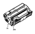
図7は、4つのプロセスユニット1Y,M,C,Kのうち、K用のプロセスユニット1Kを示す拡大斜視図である。プロセスユニット1Kのケーシングの外面には、データ記憶手段としての不揮発メモリ(フラッシュメモリ)を搭載したメモリータグ25Kが固定されている。プロセスユニット1Kがプリンタ本体に装着された状態では、図示しない接点を介して、このメモリータグ25Kとプリンタ本体の図示しないメイン制御部(詳細は後述する)とが導通する。そして、不揮発メモリ内の情報がメイン制御部に読み取られたり、不揮発メモリに対してメイン制御部によって情報が書き込まれたりする。なお、不揮発メモリには、プロセスユニットの保守管理に必要な情報として、ユニットID、製造年月日、使用開始年月日、ユニットリサイクル回数、プリント動作回数、感光体の累積表面移動距離、廃トナー累積量、満杯エラー容量などが記憶されている。メモリータグ25Kの代わりに、ICチップや非接触型ICチップを搭載したプリント基板を採用してもよい。
また、4つのプロセスユニット1Y,M,C,Kのうち、他色用のプロセスユニット1M,C,Kも、図7のK用のユニットと同様の構成になっているので説明を省略する。
FIG. 7 is an enlarged perspective view showing the
Of the four
図8は、本プリンタの電気回路の一部を示すブロック図である。同図において、メイン制御部100は、プリンタ内の各機器の駆動制御を司る制御手段として機能している。同図においては、メイン制御部100に電気接続される機器として、便宜上、光書込制御部150、及び各色のプロセスユニット1Y,M,C,Kだけを示しているが、実際には、これらの他にも様々な機器がメイン制御部100に接続されている。また、各色のプロセスユニット1Y,M,C,Kの構成要素として、便宜上、メモリータグ25Y,M,C,Kだけを示しているが、実際には、これらの他にも、ユニット内の様々な機器(例えばセンサー等)がメイン制御部100に接続されている。
FIG. 8 is a block diagram showing a part of the electric circuit of the printer. In the figure, a
光書込制御部150は、図1に示した光書込ユニット50の駆動を制御するものであり、インターフェース151、RAM(Random Access Memory)などからなる画像情報記憶部152、CPU(Central Processing Unit)153等を有している。そして、プリンタ外部のパーソナルコンピュータ等から送られてくる画像情報をインターフェース151によって取得した後、画像情報記憶部152内に一時記憶する。次いで、取得した画像情報に基づいて、各色の書込用データを生成し、このデータや、メイン制御部100から送られてくる同期信号などに基づいて各色のレーザーダイオードやポリゴンモータの駆動を制御する。
The optical
メイン制御部100は、CPU101、第1RAM102、第2RAM103、第3RAM104、ROM(Read Only Memory)105等を有している。そして、ROM105内に記憶されている制御プログラムに基づいて、各機器を制御したり、各種の演算処理を実行したりする。また、上述したように、プロセスユニット1Y,M,C,Kのメモリータグ25Kに記憶されている各種の情報を読み込んだり、メモリータグ25Kに各種の情報を書き込んだりする。
The
光書込制御部150によって生成された各色の書込用データは、光書込制御部150からメイン制御部100に送られる。メイン制御部100は転写残トナー量算出手段としての機能も有しており、転写残トナー量算出部はそれら書込データに基づいて、プリント1枚毎に、1枚あたりにおける各色(Y,M,C,K)の出力ドット数(出力画素数)を算出し、算出結果に基づいて、1枚あたりにおける各色の転写残トナー量を算出する。
The writing data for each color generated by the optical
より詳しく説明すると、メイン制御部100は転写残トナー量を算出するため、Y,M,C,Kについてそれぞれ、潜像の1ドットに対する現像トナー量予測値K1、正規帯電トナーの残留率予測値K2、感光体の単位表面移動距離あたりにおける逆帯電トナーのトナー付着量予測値K3、逆帯電トナーの残留率予測値K4、逆帯電トナーの1ドット付着量予測値K5などをROM105内に記憶している。
More specifically, since the
現像トナー量予測値K1は、1ドットあたりにおける現像ローラから感光体へのトナー付着量の予測値である。また、正規帯電トナーの残留率予測値K2は、感光体の静電潜像に付着した正規帯電トナー(本例ではマイナス帯電トナー)の1次転写ニップにおける感光体表面上での残留率の予測値であり、この値が100[%]である場合には転写残トナーは全く発生しない。また、感光体の単位表面移動距離あたりにおける逆帯電トナーのトナー付着量予測値K3は、感光体がその回転によって1[mm]表面移動する際に発生する現像ローラから感光体への逆帯電トナーの付着量予測値である。逆帯電トナー(本例ではプラス帯電)の付着は、感光体の潜像部だけでなく地肌部でも発生するので、その量は、潜像と地肌部とを区別せずに、感光体の表面移動距離に基づいて算出することが可能である。また、逆帯電トナーの残留率予測値K4は、感光体に付着した逆帯電トナーの1次転写ニップにおける感光体表面上での残留率の予測値である。また、逆帯電トナーの1ドットトナー付着量予測値K5は、感光体の潜像の1ドットあたりに対する逆帯電トナーの付着量の予測値である。これらの予測値は、プリンタ試験機を用いた予めの実験によって求められたものである。 The development toner amount prediction value K1 is a prediction value of the toner adhesion amount from the development roller to the photosensitive member per dot. Further, the estimated remaining rate K2 of the normally charged toner is a prediction of the remaining rate of the normally charged toner (minus charged toner in this example) attached to the electrostatic latent image on the surface of the photoreceptor at the primary transfer nip. If this value is 100 [%], no transfer residual toner is generated. Further, the toner adhesion amount predicted value K3 of the reversely charged toner per unit surface movement distance of the photoconductor is the reversely charged toner from the developing roller to the photoconductor generated when the photoconductor moves on the surface by 1 [mm] due to its rotation. It is the adhesion amount prediction value. Since the adhesion of the reversely charged toner (in this example, plus charge) occurs not only on the latent image portion of the photoconductor but also on the background portion, the amount of the toner does not distinguish between the latent image and the background portion. It is possible to calculate based on the moving distance. The reverse charge toner residual ratio prediction value K4 is a predicted value of the residual ratio of the reverse charge toner adhering to the photoconductor on the surface of the photoconductor in the primary transfer nip. Also, the 1-dot toner adhesion amount predicted value K5 of the reversely charged toner is a predicted value of the reversely charged toner adhesion amount per dot of the latent image on the photosensitive member. These predicted values are obtained by a prior experiment using a printer testing machine.
感光体の単位表面移動距離あたりにおける逆帯電トナーのトナー付着量予測値K3や、逆帯電トナーの1ドット付着量予測値K5については、次のようにして求めておく。即ち、図1に示した構成のプリンタ試験機を用意する。但し、プリンタ試験機の各色のプロセスユニットは、それぞれドラムクリーニング装置の廃トナー収容部が粘着テープからなる小袋になっている。かかる構成のプリンタ試験機から転写ユニット60を取り外す。そして、各色のプロセスユニットにおいて、一様帯電せしめた感光体に対して光書込を行うことなく、現像装置を空回しする。すると、感光体の全周は地肌部となり、その地肌部に現像装置内のトナーに含まれる逆帯電トナーが付着していく。この逆帯電トナーを上述の小袋内に回収していく。かかる運転を所定時間行った後、ドラムクリーニング装置から小袋を取り外す。そして、クリーニングブレードや感光体に付着している微妙のトナーを粘着テープによって回収した後、小袋及び粘着テープの重量を測定する。次いで、測定値から初期状態の小袋及び粘着テープの重量を減じて回収トナー量を求めた後、それを全運転時間における感光体表面移動距離で除算することで、単位表面移動距離あたりにおける逆帯電トナーのトナー付着量予測値K3を得る。また、このトナー付着量予測値K3を、単位表面移動距離あたりの全ドット数で除算することで、逆帯電トナーの1ドット付着量予測値K5を得る。
The toner adhesion amount predicted value K3 of the reversely charged toner per unit surface movement distance of the photoreceptor and the 1 dot adhesion amount predicted value K5 of the reversely charged toner are obtained as follows. That is, a printer testing machine having the configuration shown in FIG. 1 is prepared. However, in each color process unit of the printer testing machine, the waste toner container of the drum cleaning device is a small bag made of an adhesive tape. The
また、逆帯電トナーの残留率予測値K4については、次のようにして求めておく。即ち、上述のプリンタ試験機に転写ユニット60をセットし、逆帯電トナーのトナー付着量予測値を測定したときと同様の運転を所定時間だけ行う。但し、この際、各色の1次転写ローラ65Y,M,C,Kにそれぞれ1次転写バイアスを印加する。そして、上述の小袋及び粘着テープに回収された転写残トナーの重量を測定した後、測定結果を、予め求めておいた逆帯電トナーのトナー付着量予測値で除算して残留率予測値K4を得る。
Further, the remaining rate prediction value K4 of the reversely charged toner is obtained as follows. That is, the
また、1ドットあたりの現像トナー量予測値K1については、次のようにして求めておく。即ち、上述のプリンタ試験機から転写ユニット60を取り外す。そして、感光体の現像可能領域(現像ローラとの対向領域)に全面ベタのテスト画像を連続的に現像していきながら、そのトナーを上述の小袋内に回収していく運転を所定時間だけ行う。そして、小袋及び粘着テープに回収されたトナー量を測定した後、その結果を運転中に出力した全ドット数で除算して、1ドットあたりの現像トナー量予測値を得る。但し、この現像トナー量予測値K1には、正規帯電トナーによる付着量と、逆帯電トナーによる付着量とが含まれている。本発明においては、両者を区別する必要があるが、測定精度を高める目的から、1ドット単位では正規帯電トナーと逆帯電トナーとを区別しないことにした。よって、1ドットあたりの現像トナー量予測値K1については、正規帯電トナーと逆帯電トナーとの両方を含むものを用いる。そして、かかる現像トナー量予測値K1に基づいて求めたプリンタ1枚あたりの現像トナー量を後に補正して、正規帯電トナーだけに対応する値にする。補正方法については、後述する。
Further, the predicted development toner amount K1 per dot is obtained as follows. That is, the
また、正規帯電トナーの残留率予測値K2については、次のようにして求めておく。即ち、前述の測定において、運転中に出力した全ドット数に対応するトナー回収量には、正規帯電トナーによるものと、逆帯電トナーによるものとが含まれている。そこで、全ドット数に対応するトナー回収量から、全ドット数に対応する逆帯電トナーによる付着量(トナー付着量予測値K3に基づく値)を減じて、正規帯電トナー回収量を得る。次いで、上述のプリンタ試験機に転写ユニット60をセットし、現像トナー量予測値K1を測定したときと同様の運転を所定時間だけ行う。この際、各色の1次転写ローラ65Y,M,C,Kにそれぞれ1次転写バイアスを印加する。そして、上述の小袋及び粘着テープに回収された転写残トナーの重量を測定する。この測定結果にも、正規帯電トナー及び逆帯電トナーの両方が含まれるため、逆帯電トナーによる転写残量(逆帯電トナーの転写残量や残留率予測値K4に基づく値)を測定結果から減じる。そして、その減算結果を、上述の正規帯電トナー回収量で除算して、正規帯電トナーの残留率予測値K4を得る。このようにして得られる正規帯電トナーの残留率予測値K4は、装置構成にもよるが、本発明者らが用いたプリンタ試験機では10[%]程度になった。
Further, the remaining rate prediction value K2 of the normally charged toner is obtained as follows. That is, in the above-described measurement, the amount of toner collected corresponding to the total number of dots output during operation includes those due to regular charged toner and those due to reverse charged toner. Therefore, the amount of toner charged corresponding to the total number of dots is subtracted from the amount of adhesion of the reversely charged toner corresponding to the total number of dots (a value based on the predicted toner adhesion amount K3) to obtain the normal charged toner recovery amount. Next, the
メイン制御部100は、Y,M,C,Kの各色について、上述の書込用データから算出したプリント1枚あたりの出力ドット数に、ROM105内に記憶されている1ドットあたりの現像トナー量予測値K1を乗じて、プリント1枚あたりの現像トナー量Mg1を算出する。上述のように、この算出結果には正規帯電トナーと逆帯電トナーとの両方が含まれているので、補正によって正規帯電トナーだけに対応する値にする。具体的には、ROM内に記憶されている逆帯電トナーの1ドット付着量予測値K5と、プリント1枚あたりの出力ドット数との乗算により、プリント1枚中の画像部における逆帯電トナーの付着量を算出する。そして、算出結果の減算によってプリント1枚あたりの現像トナー量Mg1を補正するのである。
For each color of Y, M, C, and K, the
次いで、メイン制御部100は、補正後の現像トナー量累積値Mg1に、ROM105内に記憶している正規帯電トナーの残留率予測値K2を乗じて、プリント1枚あたりの正規帯電トナーの転写残量M1を算出する。そして、第1RAM102に記憶していたそれまでの正規帯電トナーの転写残量累積値Mrbを、算出結果の加算によって更新する。
Next, the
その後、メイン制御部100は、プリント1枚あたりに要した感光体の表面移動距離と、ROM105に記憶している感光体の単位表面移動距離あたりにおける逆帯電トナーのトナー付着量予測値K3との乗算により、プリント1枚あたりの逆帯電トナーの付着量を算出する。そして、算出結果と、ROM105内に記憶している逆帯電トナーの残留率予測値K4との乗算により、プリント1枚あたりの逆帯電トナーの転写残量M2を得る。更に、第2RAM103内に記憶していた逆帯電トナーの転写残量累積値Mrcを、この転写残量M2の加算によって更新する。
Thereafter, the
このようにして正規帯電トナーや逆帯電トナーの転写残量累積値(Mrb、Mrc)を更新したら、次いで、両者の加算によって廃トナー累積量Mraを算出した後、第3RAM104内に記憶していたそれまでの廃トナー累積量Mraを算出結果と同じ値に更新する。ここで注目すべき点は、従来の画像形成装置が正規帯電トナーの転写残量累積値Mrbだけを廃トナー累積量として算出していたのに対し、本プリンタでは、それと、逆帯電トナーの転写残量累積値Mrcとの合計を、廃トナー累積量Mraとしている点である。かかる構成では、正規帯電トナーの転写残量累積値Mrbだけを廃トナー累積量とする場合に比べて、廃トナー累積量Mraをより正確に求めることができる。
After updating the transfer remaining amount accumulated values (Mrb, Mrc) of the normally charged toner and the reversely charged toner in this way, the waste toner accumulated amount Mra is calculated by adding the two, and then stored in the
なお、正規帯電トナーの転写残量累積値Mrbと、逆帯電トナーの転写残量累積値Mrcとの合計を廃トナー累積量Mraとする代わりに、プリント1枚あたりにおける転写残量を正規帯電トナー、逆帯電トナーの両方について求めたら、それらの合計をそれまでの廃トナー累積量Mraに加算してもよい。 In addition, instead of setting the sum of the transfer remaining amount accumulated value Mrb of the normally charged toner and the transfer remaining amount accumulated value Mrc of the reversely charged toner as the waste toner accumulated amount Mra, the transfer remaining amount per print sheet is set as the normally charged toner. When both of the reversely charged toners are obtained, the total of them may be added to the waste toner cumulative amount Mra so far.
さらに、本プリンタでは、廃トナー累積量Mraをより正確に求めるため、廃トナー累積量Mraの算出において、逆帯電トナーの残留率予測値K4は、K用とY,M,C用とで異なる値を用いる。具体的には、K用の残留率予測値K4は70%とし、Y,M,C用は80%とした。 Further, in this printer, in order to obtain the waste toner cumulative amount Mra more accurately, in the calculation of the waste toner cumulative amount Mra, the remaining rate prediction value K4 of the reversely charged toner is different for K and Y, M, and C. Use the value. Specifically, the residual rate predicted value K4 for K is 70%, and for Y, M, and C is 80%.
これは、K色では、初期の体積平均粒径が約6μmとなる比較的的小粒径のトナーを用い、帯電電位を可変制御して、帯電電位と現像バイアスとのポテンシャルの差を常に−150Vに設定して、逆帯電トナーの付着量を最小におさえている。そこで、K色に関しては上述の逆帯電トナーの残留率予測値K4を求める際に、帯電電位と現像バイアスとのポテンシャルの差を−150Vとして測定を行う。この結果、K色の逆帯電トナーの残留率予測値K4として70%程度を得た。このように、帯電電位を可変制御するK色に関しては、実際の帯電電位と現像バイアスとのポテンシャル差に合わせた逆帯電トナーの残留率予測値K4を用いることにより、転写残量をより正確に予想することができる。これにより、廃トナー収容部22Kの満杯エラーの到来タイミングをより正確に予測でき、さらには、これに合わせた廃トナー収容部22Kの設計が可能になる。
This is because, in the K color, a toner having a relatively small particle diameter with an initial volume average particle diameter of about 6 μm is used, the charging potential is variably controlled, and the potential difference between the charging potential and the developing bias is always − By setting it to 150 V, the amount of reversely charged toner attached is minimized. Accordingly, for the K color, when the above-mentioned residual charge prediction value K4 of the reversely charged toner is obtained, the measurement is performed with the potential difference between the charged potential and the developing bias being −150V. As a result, about 70% was obtained as a predicted remaining rate K4 of the reversely charged toner of K color. As described above, with respect to the K color for variably controlling the charging potential, the remaining amount of the transfer can be more accurately determined by using the remaining charge prediction value K4 of the reversely charged toner that matches the potential difference between the actual charging potential and the developing bias. Can be expected. As a result, the arrival timing of the full error in the
一方、Y,M,C色では、初期の体積平均粒径がK色よりも粒径の大きいトナーを用い、帯電電位を−500Vに一定制御している。また、現像バイアスは−100V〜−350Vの範囲で可変制御される。このため、帯電電位と現像バイアスとのポテンシャルの差は−400V〜−150Vの範囲で変化するが、これに伴い逆帯電トナーの付着量も変化する(図6参照)。ここで、Y,M,C用の廃トナー収容部22Y,M,Cからのトナー溢れのリスクを回避するためには、最も逆帯電トナーの付着量が多くなる、帯電電位と現像バイアスとのポテンシャルの差が−400Vに合わせて、逆帯電トナーの残留率予測値K4を設定する必要がある。そこで、Y,M,C色に関しては上述の逆帯電トナーの残留率予測値K4を求める際に、帯電電位と現像バイアスとのポテンシャルの差を−400Vとして測定を行う。この結果、Y,M,C色の逆帯電トナーの残留率予測値K4として80%程度を得た。このように、帯電電位を一定制御するY,M,C色に関しては、トナー溢れのリスクを回避した安全な設計を可能にすることができる。 On the other hand, for the Y, M, and C colors, toner having an initial volume average particle size larger than that of the K color is used, and the charging potential is constantly controlled to -500V. The developing bias is variably controlled in the range of −100V to −350V. For this reason, the difference in potential between the charging potential and the developing bias changes in the range of −400 V to −150 V, but the amount of the reversely charged toner changes accordingly (see FIG. 6). Here, in order to avoid the risk of toner overflow from the waste toner storage units 22Y, M, and C for Y, M, and C, the amount of reversely charged toner that adheres most increases the charging potential and the developing bias. It is necessary to set the remaining charge prediction value K4 of the reversely charged toner in accordance with the potential difference of −400V. Therefore, for the Y, M, and C colors, the difference between the charged potential and the developing bias is measured as −400 V when the above-described residual charge prediction value K4 of the reversely charged toner is obtained. As a result, about 80% was obtained as the remaining rate prediction value K4 of the Y, M, C color reversely charged toner. As described above, for the Y, M, and C colors for which the charging potential is controlled to be constant, a safe design that avoids the risk of toner overflow can be realized.
さらに、本プリンタでは、プロセスユニット1Y,M,C,Kを使用しており、現像装置内に新たなトナーが補給されるようになっていないため、初期状態において、現像装置内に比較的多量のトナーを収容している。このトナーは、トナー供給ローラに供給される前段階において、トナー収容部に収容されているだけの状態であっても、プリント動作が行われると、撹拌部材によって撹拌され続ける。この撹拌により、トナー収容部内のトナーは、現像装置の累積稼働時間が増えていくにつれて、劣化を進行させていく。そして、トナーの劣化が進行するにつれて、逆帯電トナーの残留率が徐々に高くなっていく(転写率が徐々に低くなっていく)。このため、プロセスユニットの累積稼働時間が増えていくと、ROM105内に記憶されている逆帯電トナーの残留率予測値K4が徐々に適切な値から遠ざかっていく。そして、これにより、廃トナー累積量の算出精度が徐々に低下してしまう。
Furthermore, since this printer uses
そこで、本プリンタにおいては、現像装置の累積稼働時間の増加に伴って、逆帯電トナーの残留率予測値K4を変化させてもよい。具体的には、本プリンタでは、転写残トナー量を算出するメイン制御部100が各色のプロセスユニット1Y,M,C,Kについてそれぞれ、感光体の累積表面移動距離を上述のメモリータグ25に記憶させるようになっている。本プリンタは感光体を現像装置とは別に独立して駆動することがない仕様になっているため、感光体の累積表面移動距離は、現像装置の累積稼働時間と厳密な相関関係にある。そこで、メイン制御部100は、データテーブルをROM105内に記憶している。そして、このデータテーブルに基づいて、メモリータグに記憶されている感光体の累積表面移動距離が大きくなるにつれて、残留率予測値K4を徐々に高くしていく。具体的には、K用の残留率予測値K4は初期で70%とし、経時で80%とする。また、Y,M,C用の残留率予測値K4は初期で80%とし、経時で90%とする。このように、帯電電位を可変制御しているK用では、転写残量を正確に予想することができるため、経時の算出値の変化幅を小さく設定してもよい。一方、帯電電位を一定制御としているY,M,C用では、経時での変化幅の誤差が大きくなるため、逆帯電トナー転写残量の算出値の変化幅を大きく設定する。これにより、経時で転写率低減による転写残トナーの増大が発生したとしても廃トナー溢れのリスクを低減できる。
Therefore, in the present printer, the reversely charged toner residual rate prediction value K4 may be changed as the cumulative operating time of the developing device increases. Specifically, in this printer, the
図9は、本プリンタのメイン制御部100によって実施される廃トナー累積量の算出処理の処理フローを示すフローチャートである。この処理フローは、各色のプロセスユニットについてそれぞれ個別に実施される。また、現像装置の累積稼働時間の増加に伴って、正帯電トナーや、逆帯電トナーの残留率予測値K2、K4を変更できるものである。メイン制御部100は、算出処理を開始すると、まず、1枚プリントジョブが終了するまでフローの進行を待機した後(ステップ1:以下、ステップをSと記す)、メモリータグ内に記憶されている感光体の累積表面移動距離Dを更新する(S2)。次いで、この累積表面移動距離Dに対応する正規帯電トナーの残留率予測値K2や、逆帯電トナーの残留率予測値K4を、ROM105内のデータテーブルから特定する(S3)。そして、出力ドット数等に基づいてプリント1枚あたりの現像トナー量Mg1を算出した後(S4)、1枚あたりの逆帯電トナー付着量の減算によって現像トナー量Mg1を補正する(S5)。その後、現像トナー量Mg1と、正規帯電トナーの残留率予測値K2との乗算により、1枚あたりの正規帯電トナーの転写残量M1を算出した後(S6)、算出結果の加算によって正規帯電トナーの転写残量累積値Mrbを更新する(S7)。
FIG. 9 is a flowchart illustrating a processing flow of a calculation process of the accumulated amount of waste toner performed by the
このようにして転写残量累積値Mrbを更新したら、次に、プリント1枚あたりに要した感光体の表面移動距離D1と、単位表面移動距離あたりにおける逆帯電トナーのトナー付着量予測値K3との乗算により、プリント1枚あたりの逆帯電トナーの付着量Mxを算出する。そして、算出結果と、逆帯電トナーの残留率予測値K4との乗算により、プリント1枚あたりの逆帯電トナーの転写残量M2を得る(S8)。更に、逆帯電トナーの転写残量累積値Mrcを、この転写残量M2の加算によって更新する(S9)。 After the transfer remaining amount accumulated value Mrb is updated in this way, the surface movement distance D1 of the photosensitive member required for one print and the toner adhesion amount prediction value K3 of the reversely charged toner per unit surface movement distance Is applied to calculate the adhesion amount Mx of the reversely charged toner per print. Then, a transfer remaining amount M2 of the reversely charged toner per print is obtained by multiplying the calculation result by the predicted remaining rate K4 of the reversely charged toner (S8). Further, the transfer remaining amount cumulative value Mrc of the reversely charged toner is updated by adding the transfer remaining amount M2 (S9).
最後に、正規帯電トナーの転写残量累積値Mrbと、逆帯電トナーの転写残量累積値Mrcとの加算によって廃トナー累積量Mraを算出し(S10)、算出結果を第3RAM104やメモリータグに書き込む(S11)。
Finally, a waste toner accumulation amount Mra is calculated by adding the transfer remaining amount accumulated value Mrb of the normally charged toner and the transfer remaining amount accumulated value Mrc of the reversely charged toner (S10), and the calculation result is stored in the
また、一般に、湿度や温度が上昇するにつれて、正規帯電トナーや逆帯電トナーの残留率が徐々に高くなっていく(転写率が徐々に低くなっていく)ことが知られている。このため、湿度や温度が変化すると、残留率の適切値もそれに伴って変化する。にもかかわらず、残留率として一定の値のものを用いると、湿度や温度の変化に起因して廃トナー累積量の算出精度が低下してしまう。 Further, it is generally known that as the humidity and temperature rise, the residual rate of regular charged toner and reversely charged toner gradually increases (transfer rate gradually decreases). For this reason, when the humidity and temperature change, the appropriate value of the residual rate also changes accordingly. Nevertheless, if a constant value is used as the residual rate, the calculation accuracy of the accumulated amount of waste toner is lowered due to changes in humidity and temperature.
そこで、図示しない湿度センサーを設け、これの検知結果に基づき、逆帯電トナーの残留率予測値K4を変化させてもよい。具体的には、図示しない湿度センサーの検知結果をメイン制御部100に出力させている。そして、湿度の上昇に伴って、正規帯電トナーや逆帯電トナーの残留率予測値(K2、K4)を徐々に高くしていくようにメイン制御部100を構成している。ここでも、帯電電位を可変制御しているK用では、転写残量を正確に予想することができため、経時の算出値の変化幅を小さく設定してもよい。一方、帯電電位を一定制御としているY,M,C用では、経時での変化幅の誤差が大きくなるため、逆帯電トナー転写残量の算出値の変化幅を大きく設定する。これにより、経時で転写率低減による転写残トナーの増大が発生したとしても廃トナー溢れのリスクを低減できる。
Therefore, a humidity sensor (not shown) may be provided, and based on the detection result, the reversely charged toner residual rate prediction value K4 may be changed. Specifically, the detection result of a humidity sensor (not shown) is output to the
以上のようにして、算出手段として機能しているメイン制御部100は、各色の廃トナー累積量Mraを求めたら、それらと、メモリータグ25Y,M,C,Kに記憶されているドラムクリーニング装置の廃トナー収容部22Y,M,C,Kにおける満杯エラー容量とを比較する。そして、比較結果に基づいて、各色のプロセスユニットにおける廃トナー収容部22Y,M,C,Kについて、満杯エラーになったか否かを判定する。具体的には、算出した廃トナー累積量Mraが満杯エラー容量以上である場合に、満杯エラーであると判定する。そして、満杯エラーが発生した場合には、その旨のメッセージを報知手段としての図示しないディスプレイ等からなる表示部に表示する。音や文字画像の出力など、表示とは異なる方法でメッセージを報知してもよい。
As described above, when the
以上のような一連の制御ルーチンを、プリント1枚毎に各色についてそれぞれ行うことで、廃トナー収容部22Y,M,C,K内のトナーを検知するためのトナー検知センサーを各色のプロセスユニットにそれぞれ設けることなく、廃トナー収容部22Y,M,C,Kの満杯エラーの有無を適切に判断することができる。
A series of control routines as described above are performed for each color for each print, whereby a toner detection sensor for detecting toner in the waste
なお、正規帯電トナーや逆帯電トナーの残留率予測値(K2、K4)をROM105内に記憶させておく代わりに、転写率予測値を記憶させておいてもよい。転写率予測値は、感光体から中間転写ベルト61へのトナーの転写率予測値である。100[%]から転写率予測値を減じれば、残留率予測値になるので、このような計算によって残留率予測値を求めるようにしてもよいのである。
It should be noted that the transfer rate prediction value may be stored instead of storing the remaining rate prediction value (K2, K4) of the regular charge toner or the reverse charge toner in the
また、感光体の表面移動距離と駆動時間とは厳密な相関関係にあるので、感光体の駆動時間は実質的に表面移動距離に相当する。よって、現像トナー量予測値K1や逆帯電トナーのトナー付着量予測値K3を調整すれば、実質的な表面移動距離である駆動時間に基づいて、正規帯電トナーや逆帯電トナーの転写残量を求めることも可能である。 Further, since the surface moving distance of the photoconductor and the driving time are strictly correlated, the driving time of the photoconductor substantially corresponds to the surface moving distance. Therefore, by adjusting the development toner amount prediction value K1 and the reversely charged toner adhesion amount prediction value K3, the transfer remaining amount of the regular charge toner and the reverse charge toner can be determined based on the driving time which is a substantial surface moving distance. It is also possible to ask for it.
また、メイン制御部100は、プリント1枚毎に、メモリータグ内のプリント動作回数を1の加算によって更新したり、メモリータグ内の感光体の累積表面移動距離を所定値の加算によって更新したりする。更に、算出した各色の廃トナー累積量を第3RAM104に記憶するだけでなく、メモリータグ(25Y,M,C,K)にも記憶させる。これにより、交換されたプロセスユニットが途中まで使用された中古品であったとしても、その後の廃トナー累積量をメモリータグ内のデータに基づいて正確に求めることができる。
In addition, the
また、本プリンタでは、各色のプロセスユニット1Y,M,C,Kにそれぞれ廃トナー収容部22Y,M,C,Kを設けているが、各色ユニットのドラムクリーニング装置から廃トナーをユニット外の共通の廃トナー容器に搬送する構成を採用してもよい。この場合、各色の個別の廃トナー累積量を求め、それらの合計を廃トナー容器の満杯エラーの判定に用いればよい。
In this printer, the
以上、第一および第二の実施形態によれば、複数の感光体3Y,M,C,K上に形成したトナー像を重ね合わせてカラー画像を形成するプリンタで、K用は、鮮鋭性を向上させるため体積平均粒径の小さいトナーを用いる場合は小粒径化に伴う微粉率の上昇により逆帯電トナーが発生しやすい。このため、対応する感光体3Kの帯電装置5Kとして帯電電位を可変制御するものを用いて、かぶりトナー量を少なくするように帯電電位と現像バイアスとのポテンシャル差を最適値に設定する。一方、複数の現像手段のうち、Y,M,C用は、鮮鋭性をあまり求められないため体積平均粒径を大きいトナーを用いるので、粒径の小さいトナーに比べ逆帯電トナーが発生し難い。このため、対応する感光体3Y,M,Cの帯電装置5Y,M,Cとして帯電電位を一定制御するものを用いてもかぶりトナー量が多くなる虞は少ない。このように高画質化を図りつつ、複数の帯電手段のうち一部を帯電電位を可変制御するものを用い、それ以外は帯電電位を一定制御するものを用いることにより、画像形成装置のコストダウンを図ることができる。
同様に、微粉トナーの割合が多いトナーを用いるK用は、逆帯電トナーが発生しやすい。このため、対応する感光体3Kの帯電装置5Kとして帯電電位を可変制御するものを用いて、かぶりトナー量を少なくするように帯電電位と現像バイアスとのポテンシャル差を最適値に設定する。一方、複数の現像手段のうち、微粉トナーの割合が多いトナーを用いるY,M,C用は、逆帯電トナーが発生し難い。このため、対応する感光体3Y,M,Cの帯電装置5Y,M,Cとして帯電電位を一定制御するものを用いてもかぶりトナー量が多くなる虞はない。このように、微粒トナーの割合と帯電装置との関係を直接規定することで、より確実に高画質化を図りつつ、コストダウンを図ることができる。
また、K画像は、文字画像が多く鮮鋭性が求められるため、上述のように、トナー粒径を小さいものを用いて、より高精細な画像を得て高画質化を図るものである。一方、Y,M,C画像は、写真画像が多く鮮鋭性は求められないため、トナー粒径をK用ほど小さくしなくとも、十分に高画質な画像が得られる。
また、帯電電位を一定制御するY,M,C用の帯電装置5Y,M,Cの電源として共通帯電電源31を用いることによりコストダウンが図れる。
また、第二の実施形態によれば、感光体3Y,M,C,Kの転写残トナーを回収して廃トナーとして収容する廃トナー収容部22Y,M,C,Kの満杯検知を、感光体3Y,M,C,K上に正常に付着し得る正規帯電トナーによる転写残トナー量を算出することに加えて、感光体3Y,M,C,K上の地肌部にも付着するかぶりトナーによる転写残トナー量も算出することで、廃トナーの満杯エラーの到来タイミングをより正確に予測する。この際、逆帯電トナー量を算出するための残留率予測値K4は、K用とY,M,C用とで異なる値を用いる。K色では、帯電電位を可変制御して、転写残トナー量が最小になるよう、帯電電位と現像バイアスとのポテンシャルの差を制御している。そこで、K色に関しては、実際の帯電電位と現像バイアスとのポテンシャル差に合わせた逆帯電トナーの残留率予測値K4を用いることにより、転写残量をより正確に予想することができる。これにより、廃トナーの満杯エラーの到来タイミングをより正確に予測できる。一方、Y,M,C色では、帯電電位を一定制御しているため、帯電電位と現像バイアスとのポテンシャルの差は変化し、これに伴い逆帯電トナーの付着量も変化する。そこで、最も逆帯電トナーの付着量が多くなる、帯電電位と現像バイアスとのポテンシャルの差に合わせた逆帯電トナーの残留率予測値K4を用いる。これにより、トナー溢れのリスクを回避した安全な設計を可能にすることができる。
具体的には、K色では転写残トナー量が最小になるよう帯電電位を制御した条件で残留率予測値K4を設定し、Y,M,C色では最も逆帯電トナーの付着量が多くなる条件で残留率予測値K4を設定しているため、K色よりY,M,C色のK4が大きい。
また、経時でトナーの劣化が進行するにつれて、逆帯電トナーの残留率が徐々に高くなっていき、逆帯電トナーの残留率予測値K4が徐々に適切な値から遠ざかっていく。よって、経時で残留率予測値K4を変化させる。この際、ここでも、転写残トナー量が最小になるよう制御されるK色では、転写残量を正確に予想することができため、経時の算出値の変化幅を小さく設定してもよい。一方、帯電電位を一定制御としているY,M,C用では、経時での変化幅の誤差が大きくなるため、逆帯電トナー転写残量の算出値の変化幅を大きく設定する。これにより、経時で転写率低減による転写残トナーの増大が発生したとしても廃トナー溢れリスクを低減できる。
また、一般に、湿度や温度が上昇するにつれて、正規帯電トナーや逆帯電トナーの残留率が徐々に高くなっていく。このため、湿度や温度が変化すると、残留率の適切値もそれに伴って変化するので、逆帯電トナーの残留率予測値K4を変化させる。ここでも、転写残トナー量が最小になるよう制御されるK色では、転写残量を正確に予想することができため、経時の算出値の変化幅を小さく設定してもよい。一方、帯電電位を一定制御としているY,M,C用では、経時での変化幅の誤差が大きくなるため、逆帯電トナー転写残量の算出値の変化幅を大きく設定する。これにより、経時で転写率低減による転写残トナーの増大が発生したとしても廃トナー溢れのリスクを低減できる。
また、上記プリンタは、感光体3Y,M,C,Kを中間転写ベルト61に対して並列に配置し、モノクロモードでは、感光体3Y,M,Cを中間転写ベルト61から離間して停止させ、感光体3Kのみでトナー像を形成する。この際、K用の帯電装置5Kは、帯電電源30から電圧を供給され帯電電位を可変制御するものであり、鮮鋭性の良い高画質な画像が得られる。一方、Y,M,C用の帯電装置5Y,M,Cには、別の共通帯電電源31を用いて停止状態にすることにより、モノクロモードで感光体3Y,M,Cの無駄な使用を避けることができる。
As described above, according to the first and second embodiments, a printer for forming a color image by superimposing toner images formed on a plurality of photoconductors 3Y, 3M, 3C, and 3K has sharpness for K. In the case of using a toner having a small volume average particle diameter in order to improve, a reversely charged toner is likely to be generated due to an increase in the fine powder ratio accompanying the reduction in the particle diameter. For this reason, as the
Similarly, reverse charge toner is likely to be generated for K using toner having a high proportion of fine powder toner. For this reason, as the
Further, since the K image has many character images and requires sharpness, as described above, a higher-definition image is obtained by using a toner having a small toner particle size to improve the image quality. On the other hand, since Y, M, and C images are photographic images and do not require sharpness, a sufficiently high-quality image can be obtained even if the toner particle size is not made as small as that for K.
In addition, the cost can be reduced by using the common
In addition, according to the second embodiment, the full detection of the waste
Specifically, the remaining rate prediction value K4 is set under the condition that the charging potential is controlled so that the amount of residual toner after transfer is minimized for the K color, and the adhesion amount of the reversely charged toner is the largest for the Y, M, and C colors. Since the residual rate prediction value K4 is set under the conditions, K4 of Y, M, and C colors is larger than K color.
Further, as the toner deterioration progresses over time, the residual rate of the reversely charged toner gradually increases, and the reversely charged toner residual rate prediction value K4 gradually moves away from an appropriate value. Therefore, the residual rate prediction value K4 is changed over time. At this time, again, in the K color controlled so that the amount of residual toner is minimized, the remaining amount of transfer can be accurately predicted. Therefore, the change width of the calculated value with time may be set small. On the other hand, for Y, M, and C for which the charging potential is controlled at a constant level, the error in the change width with time increases, so the change width of the calculated value of the reversely charged toner transfer remaining amount is set large. As a result, even if the transfer residual toner increases due to the transfer rate reduction with time, the risk of waste toner overflow can be reduced.
In general, as the humidity and temperature rise, the residual rate of regular charged toner and reversely charged toner gradually increases. For this reason, when the humidity or temperature changes, the appropriate value of the residual rate also changes accordingly, and therefore the residual rate prediction value K4 of the reversely charged toner is changed. In this case as well, for the K color that is controlled so that the amount of toner remaining after transfer is minimized, the amount of remaining transfer can be accurately predicted, and the change width of the calculated value over time may be set small. On the other hand, for Y, M, and C for which the charging potential is controlled at a constant level, the error in the change width with time increases, so the change width of the calculated value of the reversely charged toner transfer remaining amount is set large. As a result, even if the transfer residual toner increases due to the transfer rate reduction with time, the risk of waste toner overflow can be reduced.
In the printer, the
1Y,M,C,K プロセスユニット
3Y,M,C,K 感光体
5Y,M,C,K 帯電装置
10Y,M,C,K 現像装置
20Y,M,C,K ドラムクリーニング装置
21Y,M,C,K クリーニングブレード
22Y,M,C,K 廃トナー収容部
30 帯電電源(可変制御)
31 共通帯電電源(一定制御)
60 転写ユニット
61 中間転写ベルト
100 メイン制御部
1Y, M, C, K Process unit 3Y, M, C,
31 Common charging power supply (constant control)
60
Claims (9)
上記複数の帯電手段として、潜像担持体の帯電電位を一定制御するものと、潜像担持体の帯電電位を可変制御するものとを備え、帯電電位を一定制御する潜像担持体に対応するトナーの体積平均粒径が、帯電電位を可変制御する潜像担持体に対応するトナーの体積平均粒径よりも大きいことを特徴とする画像形成装置。 A plurality of latent image carriers that carry a latent image on their surface; a plurality of charging means that respectively charge the surface; and a plurality of latent image writing means that respectively write latent images on the surface based on image information; An image forming apparatus comprising a plurality of developing means for developing toner by attaching each toner to the latent image on the surface, and a transfer means for transferring the toner image formed on the surface onto a transfer body.
The plurality of charging means include one that controls the charging potential of the latent image carrier and one that variably controls the charging potential of the latent image carrier, and corresponds to the latent image carrier that controls the charging potential constantly. An image forming apparatus, wherein a volume average particle diameter of toner is larger than a volume average particle diameter of toner corresponding to a latent image carrier that variably controls a charging potential.
上記複数の帯電手段として、潜像担持体の帯電電位を一定制御するものと、潜像担持体の帯電電位を可変制御するものとを備え、帯電電位を一定制御する潜像担持体に対応するトナーに含まれる微粉トナーの割合が、帯電電位を可変制御する潜像担持体に対応するトナーに含まれる微粉トナーの割合よりも小さいことを特徴とする画像形成装置。 A plurality of latent image carriers that carry a latent image on their surface; a plurality of charging means that respectively charge the surface; and a plurality of latent image writing means that respectively write latent images on the surface based on image information; An image forming apparatus comprising a plurality of developing means for developing toner by attaching each toner to the latent image on the surface, and a transfer means for transferring the toner image formed on the surface onto a transfer body.
The plurality of charging means include one that controls the charging potential of the latent image carrier and one that variably controls the charging potential of the latent image carrier, and corresponds to the latent image carrier that controls the charging potential constantly. An image forming apparatus characterized in that the proportion of fine toner contained in the toner is smaller than the proportion of fine toner contained in the toner corresponding to the latent image carrier that variably controls the charging potential.
Priority Applications (1)
| Application Number | Priority Date | Filing Date | Title |
|---|---|---|---|
| JP2008265264A JP5146829B2 (en) | 2008-10-14 | 2008-10-14 | Image forming apparatus |
Applications Claiming Priority (1)
| Application Number | Priority Date | Filing Date | Title |
|---|---|---|---|
| JP2008265264A JP5146829B2 (en) | 2008-10-14 | 2008-10-14 | Image forming apparatus |
Publications (2)
| Publication Number | Publication Date |
|---|---|
| JP2010096837A JP2010096837A (en) | 2010-04-30 |
| JP5146829B2 true JP5146829B2 (en) | 2013-02-20 |
Family
ID=42258585
Family Applications (1)
| Application Number | Title | Priority Date | Filing Date |
|---|---|---|---|
| JP2008265264A Expired - Fee Related JP5146829B2 (en) | 2008-10-14 | 2008-10-14 | Image forming apparatus |
Country Status (1)
| Country | Link |
|---|---|
| JP (1) | JP5146829B2 (en) |
Families Citing this family (2)
| Publication number | Priority date | Publication date | Assignee | Title |
|---|---|---|---|---|
| JP5327205B2 (en) * | 2010-11-24 | 2013-10-30 | ブラザー工業株式会社 | Image forming apparatus |
| EP2458445B1 (en) | 2010-11-24 | 2017-09-06 | Brother Kogyo Kabushiki Kaisha | Image forming apparatus |
Family Cites Families (2)
| Publication number | Priority date | Publication date | Assignee | Title |
|---|---|---|---|---|
| JP3625427B2 (en) * | 2000-03-08 | 2005-03-02 | キヤノン株式会社 | Image forming apparatus |
| JP2005099240A (en) * | 2003-09-24 | 2005-04-14 | Konica Minolta Business Technologies Inc | Image forming method |
-
2008
- 2008-10-14 JP JP2008265264A patent/JP5146829B2/en not_active Expired - Fee Related
Also Published As
| Publication number | Publication date |
|---|---|
| JP2010096837A (en) | 2010-04-30 |
Similar Documents
| Publication | Publication Date | Title |
|---|---|---|
| JP5353584B2 (en) | Image forming apparatus | |
| JP5102014B2 (en) | Image forming apparatus | |
| JP2007047553A (en) | Image forming apparatus and method therefor | |
| JP2009145488A (en) | Developer carrier refreshing method, image forming apparatus, image forming method, process cartridge, and developing device | |
| JP6091199B2 (en) | Image forming apparatus | |
| JP2009116130A (en) | Image forming apparatus | |
| US10234807B2 (en) | Image forming apparatus | |
| JP4826561B2 (en) | Second image forming apparatus | |
| JP2010085848A (en) | Image forming apparatus | |
| US9042744B2 (en) | Image forming apparatus | |
| JP5146829B2 (en) | Image forming apparatus | |
| JP5587056B2 (en) | Image forming apparatus | |
| JP4948100B2 (en) | Toner consumption prediction amount calculation method, toner consumption prediction amount calculation device, and image forming apparatus | |
| JP2012189688A (en) | Device for determining deterioration of rotation member, fixing device, and image forming device | |
| JP2010117636A (en) | Image forming device | |
| JP5532404B2 (en) | Image forming apparatus | |
| JP2007101755A (en) | Image forming apparatus | |
| JPH10161485A (en) | Image forming device | |
| JP4266944B2 (en) | Image forming apparatus | |
| JP2012108483A (en) | Image forming apparatus | |
| JP5904844B2 (en) | Image forming apparatus | |
| JP2004109798A (en) | Image forming apparatus, cartridge and storage medium | |
| JP2006030490A (en) | Image forming apparatus | |
| JP2007108418A (en) | Image forming apparatus | |
| JP2006195133A (en) | Image forming apparatus |
Legal Events
| Date | Code | Title | Description |
|---|---|---|---|
| A621 | Written request for application examination |
Free format text: JAPANESE INTERMEDIATE CODE: A621 Effective date: 20110905 |
|
| TRDD | Decision of grant or rejection written | ||
| A01 | Written decision to grant a patent or to grant a registration (utility model) |
Free format text: JAPANESE INTERMEDIATE CODE: A01 Effective date: 20121102 |
|
| A977 | Report on retrieval |
Free format text: JAPANESE INTERMEDIATE CODE: A971007 Effective date: 20121107 |
|
| A61 | First payment of annual fees (during grant procedure) |
Free format text: JAPANESE INTERMEDIATE CODE: A61 Effective date: 20121115 |
|
| R151 | Written notification of patent or utility model registration |
Ref document number: 5146829 Country of ref document: JP Free format text: JAPANESE INTERMEDIATE CODE: R151 |
|
| FPAY | Renewal fee payment (event date is renewal date of database) |
Free format text: PAYMENT UNTIL: 20151207 Year of fee payment: 3 |
|
| LAPS | Cancellation because of no payment of annual fees |