JP5146175B2 - Printer printing position control method and printer - Google Patents
Printer printing position control method and printer Download PDFInfo
- Publication number
- JP5146175B2 JP5146175B2 JP2008195874A JP2008195874A JP5146175B2 JP 5146175 B2 JP5146175 B2 JP 5146175B2 JP 2008195874 A JP2008195874 A JP 2008195874A JP 2008195874 A JP2008195874 A JP 2008195874A JP 5146175 B2 JP5146175 B2 JP 5146175B2
- Authority
- JP
- Japan
- Prior art keywords
- paper
- recording
- recording paper
- printing
- Prior art date
- Legal status (The legal status is an assumption and is not a legal conclusion. Google has not performed a legal analysis and makes no representation as to the accuracy of the status listed.)
- Expired - Fee Related
Links
Images


Description
本発明は、複数の給紙経路の一つから供給されるラベル用紙などの記録紙に印刷を行う
プリンタに関し、さらに詳しくは、個体差に起因する各給紙経路の印刷基準位置のバラツ
キによる記録紙幅方向の印刷ズレ、および、印刷幅の誤設定などに起因するはみ出し印刷
を防止可能なプリンタの印刷位置制御方法およびプリンタに関する。
The present invention relates to a printer that performs printing on a recording sheet such as a label sheet supplied from one of a plurality of paper feed paths, and more particularly, recording by variation in the print reference position of each paper feed path due to individual differences. The present invention relates to a printing position control method for a printer and a printer that can prevent printing out due to printing misalignment in the paper width direction and erroneous setting of the printing width.
ラベル用紙に印刷を行うプリンタでは、ラベル用紙を搬送する搬送路上で紙幅センサに
よる検出動作を行ってラベル用紙の台紙部分あるいはラベル部分の紙幅を検出し、検出結
果に基づいてプリンタの各部を制御して印刷を行っている。特許文献1には、イメージセ
ンサヘッドと反射部材をラベル幅よりも幅広に形成してラベルの上下に配置した印刷装置
が記載されており、イメージセンサヘッドから検査光を照射して、反射部材またはラベル
に反射して戻ってきた反射光をイメージセンサヘッドの各光学素子で検出することにより
、幅の異なる種々のラベルを検出できるようになっている。
In a printer that prints on label paper, the paper width sensor detects the paper width of the label paper mount or label part on the transport path that transports the label paper, and controls each part of the printer based on the detection results. Printing.
一方、ロール紙やファンフォールド紙などの異なる種類の記録紙を択一的に使用して印
刷を行うことのできるプリンタが知られている。特許文献2には、紙搬送路に形成した紙
挿入口から、ロール紙から繰り出される記録紙、および、ファンフォールド紙の一方を挿
入して紙搬送路に沿って搬送して印刷することのできるプリンタが記載されている。
異なる種類の記録紙に印刷を行うプリンタにおいて、異なる種類の記録紙に印刷を行う
ために異なる給紙経路を設け、一方の給紙経路に沿って例えばロール紙から繰り出される
記録紙を供給し、他方の給紙経路に沿って例えばファンフォールド紙を供給することが考
えられる。この場合には、ロール紙からの記録紙を供給する給紙経路を規定するロール紙
ガイドと、ファンフォールド紙を供給する給紙経路を規定する記録紙ガイドが別個に配置
される。これらのガイドによって規定される印刷基準位置の間にズレがあると、印刷位置
に供給された記録紙の幅方向の位置にズレが発生する。この結果、たとえば、一方の給紙
経路から供給される記録紙に対して幅方向にズレが生ずることなく印刷を行うことができ
たとしても、他方の給紙経路から供給される記録紙が印刷位置において幅方向にズレが生
じ、印刷位置が幅方向にズレるという不具合が発生する。このような印刷基準位置のズレ
は、各プリンタの個体差に起因して生ずるので調整が困難である。
In a printer that prints on different types of recording paper, a different paper feed path is provided to print on different types of recording paper, and the recording paper fed from, for example, roll paper is supplied along one paper feed path, It is conceivable to supply, for example, fanfold paper along the other paper feed path. In this case, a roll paper guide for defining a paper feed path for supplying recording paper from the roll paper and a recording paper guide for defining a paper feed path for supplying fanfold paper are separately arranged. If there is a deviation between the print reference positions defined by these guides, a deviation occurs in the position in the width direction of the recording paper supplied to the print position. As a result, for example, even if printing can be performed without causing a deviation in the width direction with respect to the recording paper supplied from one paper feeding path, the recording paper supplied from the other paper feeding path is printed. There is a problem that the position shifts in the width direction and the print position shifts in the width direction. Such misalignment of the print reference position is caused by individual differences among the printers and is difficult to adjust.
ここで、印刷基準位置が記録紙幅方向の中心に設定されている中心基準の場合には、記
録紙の幅に応じて左右のガイドをスライドさせて各サイズの記録紙のセット位置を規定し
ている。これに対して、幅方向の一方の端を印刷基準位置としている片側基準を採用する
場合には、基準側のガイドは一般に固定ガイドとされ、他方のガイドをセットする記録紙
幅に応じてスライドさせている。したがって、双方のガイドをスライドさせる中心基準を
採用する場合において、特に、記録紙幅方向のズレが発生しやすい。
Here, if the print reference position is the center reference set at the center in the recording paper width direction, slide the left and right guides according to the width of the recording paper to define the setting position of the recording paper of each size. Yes. On the other hand, when the one-side reference having one end in the width direction as the printing reference position is adopted, the reference-side guide is generally a fixed guide, and the other guide is slid according to the recording paper width to be set. ing. Accordingly, when the center reference for sliding both guides is employed, a shift in the recording paper width direction is particularly likely to occur.
一方、上位のコンピュータなどから供給される印刷データの記録紙幅の指定と、プリン
タにセットされている実際の記録紙の幅との間に食い違いがある場合にも印刷不良が発生
する。特に、印刷データの記録紙幅の指定誤りとして、実際にセットされている記録紙幅
よりも大きな幅が指定されていた場合には、印刷位置において記録紙以外の部位、例えば
プラテンに印刷が行われてしまう。ラベル用紙の場合には、ラベルが貼り付けられている
台紙に印刷が行われてしまう。プラテンに印刷が行われると、後続の記録紙に汚れが生ず
るおそれがある。台紙に印刷されると、台紙表面は剥離剤が塗布されておりインクが定着
しないので、プリンタ排出側の部位、操作者の手や衣類を汚すおそれがある。
On the other hand, when there is a discrepancy between the designation of the recording paper width of the print data supplied from a host computer or the like and the actual recording paper width set in the printer, a printing defect occurs. In particular, when a width larger than the actually set recording paper width is specified as an error in specifying the recording paper width of the print data, printing is performed on a portion other than the recording paper, for example, a platen at the printing position. End up. In the case of a label sheet, printing is performed on the mount on which the label is attached. When printing is performed on the platen, the subsequent recording paper may be smudged. When printing on the mount, since the surface of the mount is coated with a release agent and the ink is not fixed, there is a risk of contaminating the site on the printer discharge side, the operator's hand, and clothing.
本発明の課題は、このような点に鑑みて、複数の給紙経路の一つから供給されるラベル
用紙などの記録紙に印刷を行うに当たり、個体差に起因する各給紙経路の印刷基準位置の
バラツキなどにより生ずる記録紙幅方向の印刷ズレを防止できるようにしたプリンタの印
刷制御方法を提案することにある。
In view of these points, the present invention has an object of printing standards for each paper feed path due to individual differences in printing on recording paper such as label paper supplied from one of a plurality of paper feed paths. It is an object of the present invention to propose a printing control method for a printer that can prevent printing misalignment in the recording paper width direction caused by position variations.
また、本発明の課題は、各給紙経路から供給される記録紙に対して、プラテン、台紙な
どにはみ出し印刷が行われることのないようにしたプリンタの印刷制御方法を提案するこ
とにある。
Another object of the present invention is to propose a printing control method for a printer that prevents the printing paper supplied from each paper feed path from being overprinted on a platen, a mount or the like.
上記の課題を解決するために、本発明は、
第1給紙経路および第2給紙経路の一方から記録紙を印刷位置に供給し、当該印刷位置
において印刷ヘッドを前記記録紙の幅方向に移動させながら当該記録紙に印刷を行うプリ
ンタの印刷位置制御方法であって、
前記第1給紙経路から記録紙が搬送される場合における前記印刷ヘッドによる記録紙幅
方向の印刷基準位置を補正するための第1位置補正値と、前記第2給紙経路から記録紙が
搬送される場合における前記印刷基準位置を補正するための第2位置補正値とを記憶保持
しておき、
前記第1給紙経路から記録紙が供給される場合には、前記第1位置補正値を読み出し当
該第1位置補正値に基づき前記印刷基準位置を補正し、
前記第2給紙経路から記録紙が供給される場合には、前記第2位置補正値を読み出し当
該第1位置補正値に基づき前記印刷基準位置を補正することを特徴としている。
In order to solve the above problems, the present invention provides:
Printing of a printer that supplies recording paper from one of the first paper feeding path and the second paper feeding path to a printing position and prints on the recording paper while moving the print head in the width direction of the recording paper at the printing position A position control method,
The first position correction value for correcting the print reference position in the recording sheet width direction by the print head when the recording sheet is conveyed from the first sheet feeding path, and the recording sheet is conveyed from the second sheet feeding path. And storing a second position correction value for correcting the print reference position in the case of
When recording paper is supplied from the first paper feed path, the first position correction value is read and the print reference position is corrected based on the first position correction value.
When recording paper is supplied from the second paper feed path, the second position correction value is read and the print reference position is corrected based on the first position correction value.
本発明のプリンタの印刷位置制御方法では、例えば、印刷基準位置の補正値を実測によ
り求めて記憶保持するようにしている。この場合には、プリンタの出荷前において実際の
プリンタを駆動して設定されている印刷基準位置を基準として各給紙経路から印刷位置に
供給される記録紙に対して印刷ヘッドにより印刷を行い、幅方向に印刷ズレがある場合に
は、その印刷ズレを解消できるように第1、第2位置補正値を算出して記憶保持すればよ
い。本発明によれば、プリンタの個体差に起因する給紙経路別の幅方向の印刷ズレを防止
でき、いずれの給紙経路を用いて記録紙を供給した場合においても適切な印刷を行うこと
ができる。
In the printer printing position control method of the present invention, for example, a correction value for the printing reference position is obtained by actual measurement and stored. In this case, printing is performed by the print head on the recording paper supplied from each paper feed path to the printing position with reference to the printing reference position set by driving the actual printer before shipping the printer, If there is a print misalignment in the width direction, the first and second position correction values may be calculated and stored so that the print misalignment can be eliminated. According to the present invention, it is possible to prevent printing misalignment in the width direction for each paper feed path due to individual differences between printers, and appropriate printing can be performed when recording paper is supplied using any paper feed path. it can.
ここで、本発明のプリンタの印刷位置制御方法においては、電源投入時に、前記第1給
紙経路から前記記録紙が供給される第1給紙モードおよび前記第2給紙経路から前記記録
紙が供給される第2給紙モードのいずれが設定されているのかを判別し、記憶保持されて
いる前記第1、第2位置補正値のうち、判別された給紙モードに対応する位置補正値を読
み出し、前記印刷ヘッドによる印刷時には、読み出された前記位置補正値を用いて前記印
刷基準位置を補正して補正印刷基準位置を算出することが望ましい。例えば、第1、第2
位置補正値を不揮発性メモリに記憶保持しておき、電源投入時に、これらを読み出して、
作業用の一時記憶メモリに保持して使用すればよい。
Here, according to the printing position control method of the printer of the present invention, when the power is turned on, the recording paper is supplied from the first paper supply path and the recording paper is supplied from the second paper supply path. It is determined which of the supplied second sheet feeding modes is set, and the position correction value corresponding to the determined sheet feeding mode is stored among the first and second position correction values stored and held. At the time of reading and printing by the print head, it is desirable to calculate the corrected printing reference position by correcting the printing reference position using the read position correction value. For example, first, second
The position correction values are stored in nonvolatile memory and read out when the power is turned on.
What is necessary is just to hold | maintain and use in the temporary storage memory for work.
次に、本発明のプリンタの印刷位置制御方法は、
紙幅センサを用いて前記印刷位置に供給される前記記録紙の紙幅を検出し、
印刷データによる印刷幅が前記紙幅よりも広い場合には、印刷データにおける前記紙幅
から外れて印刷されるデータ部分を、印刷されないようにマスク処理を行うことを特徴と
している。
Next, the printing position control method of the printer of the present invention includes:
Detecting a paper width of the recording paper supplied to the printing position using a paper width sensor;
When the print width based on the print data is wider than the paper width, a mask process is performed so that a data portion printed out of the paper width in the print data is not printed.
例えば、印刷データに含まれる記録紙幅指定に誤りがあり、印刷データの印刷幅がセッ
トされている記録紙の紙幅よりも広い場合であっても、記録紙の幅方向に外れた位置に印
刷が行われることがない。よって、印刷位置において記録紙をガイドするためのプラテン
上にインクが付着して汚れてしまうことがない。また、ラベル用紙に印刷を行う場合には
、ラベル以外の部分、例えば台紙がインクで汚れてしまうことがない。
For example, even if there is an error in the recording paper width specification included in the print data and the print data print width is wider than the set recording paper width, printing is performed at a position deviated in the width direction of the recording paper. Never done. Therefore, the ink does not adhere to the platen for guiding the recording paper at the printing position and is not stained. In addition, when printing on label paper, portions other than the label, for example, the mount, do not get stained with ink.
ここで、前記マスク処理に当たっては、前記紙幅センサによる検出誤差を考慮して、検
出された前記紙幅よりも狭い紙幅と前記印刷データによる印刷幅を比較することが望まし
い。
Here, in the mask process, it is preferable to compare a paper width narrower than the detected paper width with a print width based on the print data in consideration of a detection error by the paper width sensor.
また、マスク処理は次のように行うことができる。まず、前記紙幅センサによって、前
記記録紙の第1紙端位置および他方の第2紙端位置を検出する。次に、マスク処理におい
て、前記第1紙端位置および前記第2紙端位置に対して記録紙幅方向の内側に第1寸法だ
け移動した第1内側端位置および第2内側端位置を算出する。前記印刷データの印刷幅を
規定する記録紙幅方向の一方の第1印刷端位置が、前記第1内側端位置よりも外側にある
場合には、前記第1紙端位置から前記第1寸法より大きな第2寸法だけ記録紙幅方向の内
側に移動した位置を算出し、当該位置から前記第1印刷端位置までの範囲に印刷される印
刷データの部分を、印刷されないようにマスクする。同様に、前記印刷データの印刷幅を
規定する記録紙幅方向の他方の第2印刷端位置が、前記第2内側端位置よりも外側にある
場合には、前記第2紙端位置から前記第2寸法だけ記録紙幅方向の内側に移動した位置を
算出し、当該位置から前記第2印刷端位置までの範囲に印刷される印刷データの部分を、
印刷されないようにマスクする。
The mask process can be performed as follows. First, the first paper edge position and the other second paper edge position of the recording paper are detected by the paper width sensor. Next, in the mask process, a first inner end position and a second inner end position that are moved by a first dimension inward in the recording paper width direction with respect to the first paper end position and the second paper end position are calculated. When one first print end position in the recording paper width direction defining the print width of the print data is outside the first inner end position, the first dimension is larger than the first dimension from the first paper end position. A position moved inward in the recording paper width direction by the second dimension is calculated, and a portion of print data printed in a range from the position to the first print end position is masked so as not to be printed. Similarly, when the other second print end position in the recording paper width direction defining the print width of the print data is outside the second inner end position, the second print end position is changed from the second paper end position to the second paper end position. The position moved to the inside in the recording paper width direction by the dimension is calculated, and the portion of the print data printed in the range from the position to the second print end position is
Mask from printing.
このようにすれば、印刷データの印刷幅が検出された記録紙の紙幅よりも広く、その外
側にはみ出して印刷される場合には、はみ出して印刷される部分が印刷されないようにマ
スクが掛けられる。また、その際に、記録紙の端から第2寸法分だけ内側に入った位置ま
でをマスクしているので、はみ出し印刷を確実に回避できる。例えば、第2寸法を、使用
するラベル用紙における台紙の端からラベルの端までの間の寸法よりも大きな値に設定し
ておくことにより、印刷がラベルから外れた台紙の端の部分に行なわれてしまうことを確
実に防止できる。
In this way, when the print width of the print data is wider than the detected recording paper width and the print data is printed outside the print paper, the mask is applied so that the portion that is printed out is not printed. . Further, at this time, the printing is masked from the end of the recording paper to the position inside the second dimension, so that the overprinting can be surely avoided. For example, by setting the second dimension to a value larger than the dimension between the end of the label in the label paper to be used and the end of the label, printing is performed on the end of the mount that is off the label. Can be surely prevented.
次に、前記第1給紙経路から供給される記録紙はロール紙から繰り出される記録紙とす
ることができ、前記第2給紙経路から供給される記録紙はファンフォールド紙とすること
ができる。
Next, the recording paper supplied from the first paper feed path can be a recording paper fed out from a roll paper, and the recording paper supplied from the second paper feed path can be a fanfold paper. .
この場合には、前記第1給紙経路には開閉カバー付きのロール紙収納部に収納したロー
ル紙から繰り出される記録紙を供給し、前記第2給紙経路には手差し口から挿入されるフ
ァンフォールド紙を供給するように構成することができる。この構成を採用した場合には
、前記紙幅センサによる前記記録紙の紙幅検出を、少なくとも、電源投入時、前記開閉カ
バーが閉じたことが検出された時点、前記手差し口に前記ファンフォールド紙が挿入され
たことが検出された時点のいずれかにおいて行なうようにすればよい。これらの事象が発
生する前の段階において、記録紙交換などが行なわれている可能性が高いからである。
In this case, recording paper fed out from the roll paper stored in the roll paper storage unit with an open / close cover is supplied to the first paper supply path, and a fan inserted from the manual feed port to the second paper supply path. It can be configured to supply fold paper. When this configuration is adopted, the paper width detection of the recording paper by the paper width sensor is performed at least when the opening / closing cover is detected to be closed when the power is turned on, and the fanfold paper is inserted into the manual feed slot. It may be performed at any time point when it has been detected. This is because there is a high possibility that the recording paper is exchanged in the stage before these events occur.
また、本発明は次のように適用することができる。 Further, the present invention can be applied as follows.
(適用例1)(Application example 1)
上位機器と接続可能であり、少なくとも第1給紙経路を備え、前記第1給紙経路により記録紙を供給し、印刷ヘッドを記録紙幅方向に移動させながら前記記録紙に印刷を行うプリンタの印刷位置制御方法であって、 Printing of a printer that can be connected to a host device, has at least a first paper feed path, supplies recording paper through the first paper feed path, and prints on the recording paper while moving a print head in the width direction of the recording paper A position control method,
前記第1給紙経路により供給される前記記録紙に対し前記印刷ヘッドの記録紙幅方向の印刷基準位置を補正するための第1位置補正値を記憶しておき、 Storing a first position correction value for correcting a print reference position of the print head in the recording sheet width direction with respect to the recording sheet supplied by the first sheet feeding path;
前記第1位置補正値を読み出して前記印刷基準位置を補正して補正印刷基準位置とし、 Reading out the first position correction value and correcting the print reference position as a corrected print reference position;
前記上位機器から印刷データを受信すると、前記印刷データと前記補正印刷基準位置とに基づき、前記印刷データを印刷するときの印刷幅の記録紙幅方向の一方の端である第1印刷端位置と他方の端である第2印刷端位置を算出し、 When print data is received from the host device, the first print end position which is one end in the recording paper width direction of the print width when printing the print data and the other based on the print data and the corrected print reference position 2nd printing edge position which is the edge of
紙幅検出器を用いて、ホームポジションを基準として、前記第1給紙経路により供給される前記記録紙の一方の端である第1紙端位置および他方の端である第2紙端位置を検出し、 Using a paper width detector, a first paper end position that is one end of the recording paper supplied by the first paper feed path and a second paper end position that is the other end are detected based on the home position. And
前記第1紙端位置および前記第2紙端位置に対して前記記録紙の記録紙幅方向の中央側に向かって第1寸法だけ移動した第1内側端位置および第2内側端位置を算出し、 Calculating a first inner edge position and a second inner edge position which are moved by a first dimension toward the center side in the recording paper width direction of the recording paper with respect to the first paper edge position and the second paper edge position;
前記第1印刷端位置が前記第1内側端位置よりも記録紙幅方向の外側にある場合には、前記第1紙端位置から前記第1寸法より大きな第2寸法だけ前記記録紙の記録紙幅方向の中央側に向かって移動した位置を算出し、当該位置から前記第1印刷端位置までの範囲に印刷されるべき前記印刷データの部分を、印刷しないようにマスク処理し、 When the first printing end position is outside the first inner end position in the recording sheet width direction, the recording sheet width direction of the recording sheet is larger by the second dimension than the first dimension from the first sheet end position. Calculating the position moved toward the center of the image, masking the portion of the print data to be printed in a range from the position to the first print end position so as not to print,
前記第2印刷端位置が前記第2内側端位置よりも記録紙幅方向の外側にある場合には、前記第2紙端位置から前記第2寸法だけ記録紙幅方向の前記記録紙の中央側に向かって移動した位置を算出し、当該位置から前記第2印刷端位置までの範囲に印刷されるべき前記印刷データの部分を、印刷しないようにマスク処理することを特徴とするプリンタの印刷位置制御方法。 When the second print end position is outside the second inner end position in the recording paper width direction, the second print end position is directed from the second paper end position to the center side of the recording paper in the recording paper width direction by the second dimension. A printing position control method for a printer, wherein the position of the print data is calculated, and a portion of the print data to be printed in a range from the position to the second printing end position is masked so as not to be printed .
(適用例2)(Application example 2)
前記プリンタは、第2給紙経路を備え、 The printer includes a second paper feed path,
前記第2給紙経路により供給される前記記録紙に対し前記印刷ヘッドの記録紙幅方向の印刷基準位置を補正するための第2位置補正値を記憶しておき、 Storing a second position correction value for correcting the print reference position of the print head in the recording paper width direction with respect to the recording paper supplied by the second paper feed path;
電源投入時に、前記第1給紙経路から前記記録紙が供給される第1給紙モードおよび前記第2給紙経路から前記記録紙が供給される第2給紙モードのいずれが設定されているのかを判別し、 Either a first paper supply mode in which the recording paper is supplied from the first paper supply path or a second paper supply mode in which the recording paper is supplied from the second paper supply path when the power is turned on is set. To determine whether
前記上位機器から印刷データを受信すると、記憶されている前記第1位置補正値および前記第2位置補正値のうち判別された給紙モードに対応する位置補正値を読み出し、前記印刷基準位置を前記補正印刷基準位置に補正することを特徴とする上述のプリンタの印刷位置制御方法。 When print data is received from the host device, a position correction value corresponding to the determined paper feed mode is read out of the stored first position correction value and second position correction value, and the print reference position is set as the print reference position. The above-described printer printing position control method, wherein the correction printing reference position is corrected.
(適用例3)(Application example 3)
前記マスク処理に当たっては、前記紙幅検出器による検出誤差に基づき、検出された前記紙幅よりも狭い紙幅とすることを特徴とする上述のプリンタの印刷位置制御方法。 In the mask processing, the printing position control method for a printer described above, wherein the paper width is narrower than the detected paper width based on a detection error by the paper width detector.
(適用例4)(Application example 4)
前記記録紙は台紙にラベルが貼付されたものであり、前記第2寸法は、前記台紙の端から前記ラベルの端までの台紙部分の寸法より大きい値とすることを特徴とする上述のプリンタの印刷制御方法。 The above-mentioned printer is characterized in that the recording sheet has a label affixed to a mount, and the second dimension is larger than the dimension of the mount portion from the end of the mount to the end of the label. Print control method.
(適用例5)(Application example 5)
前記第1給紙経路には開閉カバー付きのロール紙収納部に収納したロール紙から繰り出される記録紙が供給され、前記第2給紙経路には手差し口から挿入されるファンフォールド紙が供給されるようになっており、 Recording paper fed from roll paper stored in a roll paper storage unit with an open / close cover is supplied to the first paper supply path, and fanfold paper inserted from a manual feed port is supplied to the second paper supply path. It is supposed to
前記紙幅検出器による前記記録紙の紙幅検出を、少なくとも、前記開閉カバーが閉じたことが検出された時点、および、前記手差し口に前記ファンフォールド紙が挿入されたことが検出された時点のいずれかにおいて行なうことを特徴とする上述のプリンタの印刷位置制御方法。 The paper width detection of the recording paper by the paper width detector is at least either when the opening / closing cover is detected to be closed or when the fanfold paper is detected to be inserted into the manual feed slot. A method for controlling the printing position of the printer as described above.
(適用例6)(Application example 6)
上位機器と接続可能なプリンタであって、 A printer that can be connected to a host device,
記録紙幅方向へ移動しながら記録紙に印刷する印刷ヘッドと、 A print head for printing on recording paper while moving in the recording paper width direction;
前記記録紙を供給する第1給紙経路と、 A first paper feed path for feeding the recording paper;
前記記録紙の紙幅を検出する紙幅検出器と、 A paper width detector for detecting the paper width of the recording paper;
前記第1給紙経路により供給される前記記録紙に対し、前記印刷ヘッドの記録紙幅方向の印刷基準位置を補正するための第1位置補正値を記憶する記憶部と、 A storage unit for storing a first position correction value for correcting a print reference position of the print head in the recording sheet width direction with respect to the recording sheet supplied by the first sheet feeding path;
前記印刷ヘッドによる印刷動作を制御する制御手段と、を備え、 Control means for controlling a printing operation by the print head,
前記制御手段は、 The control means includes
前記第1位置補正値を読み出して前記印刷基準位置を補正して補正印刷基準位置とし、 Reading out the first position correction value and correcting the print reference position as a corrected print reference position;
前記上位機器から印刷データを受信すると、前記印刷データと前記補正印刷基準位置とに基づき、前記印刷データを印刷するときの印刷幅の記録紙幅方向の一方の端である第1印刷端位置と他方の端である第2印刷端位置を算出し、 When print data is received from the host device, the first print end position which is one end in the recording paper width direction of the print width when printing the print data and the other based on the print data and the corrected print reference position 2nd printing edge position which is the edge of
前記紙幅検出器を用いて、ホームポジションを基準として、前記第1給紙経路により供給される前記記録紙の一方の端である第1紙端位置および他方の端である第2紙端位置を検出し、 Using the paper width detector, a first paper end position which is one end of the recording paper supplied by the first paper feed path and a second paper end position which is the other end of the recording paper supplied from the home position are used as a reference. Detect
前記第1紙端位置および前記第2紙端位置に対して前記記録紙の記録紙幅方向の中央側に向かって第1寸法だけ移動した第1内側端位置および第2内側端位置を算出し、 Calculating a first inner edge position and a second inner edge position which are moved by a first dimension toward the center side in the recording paper width direction of the recording paper with respect to the first paper edge position and the second paper edge position;
前記第1印刷端位置が前記第1内側端位置よりも記録紙幅方向の外側にある場合には、前記第1紙端位置から前記第1寸法より大きな第2寸法だけ前記記録紙の記録紙幅方向の中央側に向かって移動した位置を算出し、当該位置から前記第1印刷端位置までの範囲に印刷されるべき前記印刷データの部分を、印刷しないようにマスク処理し、 When the first printing end position is outside the first inner end position in the recording sheet width direction, the recording sheet width direction of the recording sheet is larger by the second dimension than the first dimension from the first sheet end position. Calculating the position moved toward the center of the image, masking the portion of the print data to be printed in a range from the position to the first print end position so as not to print,
前記第2印刷端位置が前記第2内側端位置よりも記録紙幅方向の外側にある場合には、前記第2紙端位置から前記第2寸法だけ記録紙幅方向の前記記録紙の中央側に向かって移動した位置を算出し、当該位置から前記第2印刷端位置までの範囲に印刷されるべき前記印刷データの部分を、印刷しないようにマスク処理することを特徴とするプリンタ。 When the second print end position is outside the second inner end position in the recording paper width direction, the second print end position is directed from the second paper end position to the center side of the recording paper in the recording paper width direction by the second dimension. A printer that calculates the moved position and masks the portion of the print data to be printed in a range from the position to the second print end position so as not to print.
(適用例7)(Application example 7)
第2給紙経路と、前記第1給紙経路から前記記録紙が供給される第1給紙モードおよび前記第2給紙経路から前記記録紙が供給される第2給紙モードのいずれかを設定する設定手段を備え、 One of a second paper feeding path, a first paper feeding mode in which the recording paper is supplied from the first paper feeding path, and a second paper feeding mode in which the recording paper is supplied from the second paper feeding path. With setting means for setting,
前記記憶部は、前記第2給紙経路により供給される前記記録紙に対し前記印刷ヘッドによる記録紙幅方向の印刷基準位置を補正するための第2位置補正値を記憶し、 The storage unit stores a second position correction value for correcting a print reference position in a recording sheet width direction by the print head with respect to the recording sheet supplied by the second sheet feeding path.
前記制御手段は、 The control means includes
電源投入時に、前記設定手段が前記第1給紙モードおよび前記第2給紙モードのいずれが設定されているのかを判別し、 When the power is turned on, the setting means determines which of the first paper feed mode and the second paper feed mode is set,
前記上位機器から印刷データを受信すると、前記記憶部に記憶されている前記第1位置補正値および前記第2位置補正値のうち判別された給紙モードに対応する位置補正値を読み出し、前記印刷基準位置を前記補正印刷基準位置に補正することを特徴とする上述のプリンタ。 When print data is received from the host device, a position correction value corresponding to the determined paper feed mode is read from the first position correction value and the second position correction value stored in the storage unit, and the print The printer described above, wherein a reference position is corrected to the corrected printing reference position.
(適用例8)(Application example 8)
前記制御手段は、 The control means includes
前記マスク処理に当たっては、前記紙幅検出器による検出誤差に基づき、検出された前記紙幅よりも狭い紙幅とすることを特徴とする上述のプリンタ。 In the masking process, the paper width is narrower than the detected paper width based on a detection error by the paper width detector.
(適用例9)(Application example 9)
前記記録紙は台紙にラベルが貼付されたものであり、前記第2寸法は、前記台紙の端から前記ラベルの端までの台紙部分の寸法より大きい値とすることを特徴とする上述のプリンタ。 The above-mentioned printer, wherein the recording paper is a label affixed to a mount, and the second dimension is larger than the dimension of the mount portion from the end of the mount to the end of the label.
(適用例10)(Application example 10)
前記第1給紙経路側に備えられる開閉カバー付きのロール紙収納部と、 A roll paper storage section with an open / close cover provided on the first paper feed path side;
前記開閉カバーの開閉を検出するカバー検出器と、 A cover detector for detecting opening and closing of the opening and closing cover;
前記第2給紙経路側に備えられる手差し口と、 A manual feed opening provided on the second paper feed path side;
前記手差し口に前記ファンフォールド紙が挿入されたことが検出する挿入検出器と、を有し、 An insertion detector that detects that the fanfold paper has been inserted into the manual feed port, and
前記第1給紙経路から供給される記録紙は、前記ロール紙収納部に収納されたロール紙から繰り出される記録紙であり、 The recording paper supplied from the first paper feed path is a recording paper fed out from the roll paper stored in the roll paper storage unit,
前記第2給紙経路から供給される記録紙は、手差し口から挿入される前記ファンフォールド紙であり、 The recording paper supplied from the second paper feed path is the fanfold paper inserted from the manual feed port,
前記紙幅検出器による前記記録紙の紙幅検出を、少なくとも、前記カバー検出器が前記開閉カバーが閉じたことを検出した時点、および、前記挿入検出器が前記手差し口に前記ファンフォールド紙が挿入されたことを検出した時点の、いずれかにおいて行なうことを特徴とする上述のプリンタ。 The paper width detection of the recording paper by the paper width detector is performed at least when the cover detector detects that the opening / closing cover is closed, and the insertion detector inserts the fanfold paper into the manual feed port. The printer as described above, which is performed at any time when it is detected.
本発明のプリンタの印刷位置制御方法、および、当該方法を用いたプリンタでは、印刷
基準位置の補正値を記憶保持するようにしている。例えば、プリンタの出荷前において実
際のプリンタを駆動して設定されている印刷基準位置を基準として各給紙経路から印刷位
置に供給される記録紙に対して印刷ヘッドにより印刷を行い、幅方向に印刷ズレがある場
合には、その印刷ズレを解消できるように第1、第2位置補正値を算出して記憶保持する
ようにしている。したがって、プリンタの個体差に起因する給紙経路別の幅方向の印刷ズ
レを防止でき、いずれの給紙経路を用いて記録紙を供給した場合においても適切な印刷を
行うことができる。
In the printer printing position control method of the present invention and the printer using the method, the correction value of the printing reference position is stored and held. For example, printing is performed by a print head on a recording sheet supplied from each paper feed path to a printing position based on a printing reference position set by driving an actual printer before shipping the printer, If there is a print misalignment, the first and second position correction values are calculated and stored so that the print misalignment can be eliminated. Accordingly, it is possible to prevent printing misalignment in the width direction for each paper feed path due to individual differences between printers, and appropriate printing can be performed even when recording paper is supplied using any paper feed path.
以下に、図面を参照して、本発明を適用したプリンタの実施の形態を説明する。 Embodiments of a printer to which the present invention is applied will be described below with reference to the drawings.
(全体構成)
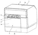
図1は本発明の実施の形態に係るプリンタの外観斜視図であり、図2はその開閉カバー
を全開にした状態の外観斜視図である。プリンタ1は全体としてほぼ直方体形状をしたプ
リンタ本体2と、このプリンタ本体2の前面に取り付けた開閉カバー3とを有している。
プリンタ本体2の外装ケース2aの前面には所定幅の記録紙排出口4が形成されている。
記録紙排出口4の下側には排紙ガイド5が前方に突出しており、当該排紙ガイド5の側方
には開閉レバー6が配置されている。外装ケース2aにおける排紙ガイド5および開閉レ
バー6の下側には、ロール紙出し入れ用の矩形の開口部2bが形成されており、この開口
部2bが開閉カバー3によって封鎖されている。開閉カバー3の開閉は、外装ケース2a
における開口部2bの近傍に配置した開閉センサ2cによって検出可能となっている。
(overall structure)
FIG. 1 is an external perspective view of a printer according to an embodiment of the present invention, and FIG. 2 is an external perspective view of a state in which the opening / closing cover is fully opened. The
A recording paper discharge port 4 having a predetermined width is formed on the front surface of the
A
It can be detected by an open /
開閉レバー6を操作すると開閉カバー3のロックが解除される。排紙ガイド5を前方に
引くと、図2に示すように、開閉カバー3が下端部を中心として前方にほぼ水平となるま
で開く。開閉カバー3が開くと、プリンタ本体2の内部に形成されているロール紙収納部
7が開放状態となる。同時に、印刷位置を規定するための吸引プラテン8が開閉カバー3
と一緒に移動してロール紙収納部7から記録紙排出口4に至る空間が開放状態となり、プ
リンタ前方からロール紙9を簡単に装填できるようになっている。
When the open /
The space from the roll
また、プリンタ1はファンフォールド紙10を使用することが可能になっており、ファ
ンフォールド紙10は、プリンタ本体2の背面部分に形成されている記録紙挿入口11(
図3参照)から、プリンタ本体2の内部に手差し挿入される。なお、図2ではカバーケー
ス3aおよび開閉レバー6を省略してある。
In addition, the
3), the printer is manually inserted into the
図3はプリンタ1の内部の概略構成を示す説明図である。プリンタ1の内部には、プリ
ンタ本体フレーム12における幅方向の中央部分にロール紙収納部7が形成されている。
ロール紙収納部7にはロール紙9がプリンタ幅方向に向いた横置き状態で収納される。ロ
ール紙収納部7の後方には、ロール紙9から繰り出される長尺状の記録紙9aを搬送する
ための繰り出しローラ13が配置されている。
FIG. 3 is an explanatory diagram showing a schematic configuration inside the
The
ロール紙収納部7の上側には、プリンタ本体フレーム12の上端にヘッドユニットフレ
ーム14が水平に取り付けられている。ヘッドユニットフレーム14には、インクジェッ
トヘッド15、このインクジェットヘッド15を搭載しているキャリッジ16、キャリッ
ジ16のプリンタ幅方向への移動をガイドするキャリッジガイド軸17、キャリッジ16
をキャリッジガイド軸17に沿って往復移動させるためのキャリッジモータ18およびタ
イミングベルト19を備えたキャリッジ搬送機構が配置されている。インクジェットヘッ
ド15は、インクノズル面15aが下向きになるようにキャリッジ16に搭載されている
。ヘッドユニットフレーム14の前端位置には固定刃および可動刃からなるオートカッタ
20が配置されている。
A
A carriage transport mechanism including a
インクジェットヘッド15の下側には一定のギャップを開けてプリンタ幅方向に水平に
延びる吸引プラテン8が配置されている。吸引プラテン8は直方体形状をしており、プラ
テン表面8aの所定領域には多数の吸引孔が形成されている。不図示の吸引機構によって
これら吸引孔から空気を吸い込むことにより、プラテン表面8aに記録紙9a、ファンフ
ォールド紙10を吸引しながら搬送でき、これによって、プラテンギャップを一定に保持
することができる。
A
吸引プラテン8の後側には送り出しローラ21がプリンタ幅方向に水平に架け渡されて
おり、送り出しローラ21には所定幅の紙押さえローラ22が所定の押圧力で押し付けら
れている。送り出しローラ21は、プリンタ本体フレーム12に搭載されている紙送りモ
ータ23によって駆動される。吸引プラテン8における前端側の部位には前側紙押さえロ
ーラ24が配置されている。前側紙押さえローラ24は記録紙9aやファンフォールド紙
10の浮き上がりを防止するものであり、記録紙排出口4に送り出される記録紙9a、フ
ァンフォールド紙10の送り出しに連動して連れ回りする。
On the rear side of the
吸引プラテン8の前端には排紙ガイド5が取付けられている。吸引プラテン8の前端に
おけるプリンタ本体フレーム12およびヘッドユニットフレーム14の間の部位は一定幅
の隙間が開いており、この隙間が記録紙排出口4になっている。
A
吸引プラテン8の下側には、ロール紙押さえレバー25が後方に向かって斜め下方に延
びるように取付けられている。ロール紙押さえレバー25はバネ力によって下方に付勢さ
れており、その先端部分に取り付けられているロール紙押さえローラ26が繰り出しロー
ラ13に所定の押圧力で押し付けられている。
A roll
吸引プラテン8の後端には下方に湾曲しているテンションガイド27が取り付けられて
いる。テンションガイド27はバネ力によって上方に付勢されており、テンションガイド
27によって記録紙9aには所定の張力が付与される。
A
テンションガイド27の後方には後側紙押さえローラ28が配置されている。後側紙押
さえローラ28の後方のプリンタ本体フレーム12の部位には、プリンタ本体2の背面側
からファンフォールド紙10を受け入れるための記録紙挿入口11が形成されている。ま
た、プリンタ本体フレーム12の記録紙挿入口11が形成されている部位の外側には、フ
ァンフォールド紙10をこの記録紙挿入口11まで導くための導入路29を備えたファン
フォールド紙ホルダ30が取付けられている。
A rear
ここで、ロール紙収納部7に収納されているロール紙9から繰り出される長尺状の記録
紙9aを搬送する第1給紙経路Aは、繰り出しローラ13およびテンションガイド27の
ニップ部を経由した後に、上方に引き出されてテンションガイド27を経由して前方に湾
曲するように引き出され、しかる後に、送り出しローラ21および紙押さえローラ22の
ニップ位置を経由して、プラテン表面8aに沿ってインクジェットヘッド15による印刷
位置およびオートカッタ20による切断位置および記録紙排出口4を順に経由して水平に
延びている。この第1給紙経路Aに沿って搬送される記録紙9aの幅方向の位置は、ロー
ル紙収納部7の両側に配置されている可動式ガイド7a、7b(図2参照)によって規定
される。すなわち、本例では、ロール紙9の幅に対応させて左右の可動式ガイド7a、7
bをスライドさせて、ロール紙9の位置、したがって、そこから繰り出される記録紙9a
の幅方向の位置を、中央基準によって規定している。
Here, the first paper feed path A for transporting the
b is slid, and the position of the
The position in the width direction is defined by the central reference.
また、導入路29から手差しで挿入されるファンフォールド紙10を搬送する第2給紙
経路Bは、記録紙挿入口11から後側紙押さえローラ28、送り出しローラ21および紙
押さえローラ22のニップ部を経由して水平に引き出された後に、プラテン表面8aに沿
ってインクジェットヘッド15による印刷位置を経由した後に、オートカッタ20による
切断位置および記録紙排出口4を順次に経由して水平に延びている。第1給紙経路Aと第
2給紙経路Bは、送り出しローラ21および紙押さえローラ22のニップ部から下流側の
部分が共通経路となっている。この第2給紙経路Aに沿って搬送されるファンフォールド
紙10の幅方向の位置は、導入路29の両側壁を規定している可動式ガイド29a、29
bによって規定される。すなわち、ファンフォールド紙10の幅に対応させて左右の可動
式ガイド29a、29bをスライドさせて、ファンフォールド紙10の幅方向の位置を、
中央基準によって規定している。
The second paper feed path B for conveying the
defined by b. That is, the left and right
It is defined by the central standard.
次に、記録紙挿入口11にはファンフォールド紙10の有無を検出するための紙挿入検
出器31が配置されている。紙挿入検出器31は記録紙挿入口11においてファンフォー
ルド紙の搬送経路内に突出している検出レバー31aを備えている。記録紙挿入口11に
差し込まれたファンフォールド紙10によって検出レバー31aが押されることによって
、ファンフォールド紙10が挿入されたことを検出する。
Next, a
インクジェットヘッド15が搭載されているキャリッジ16には、例えば反射型フォト
センサからなる紙幅センサ33が搭載されている。紙幅センサ33は、記録紙搬送方向と
は直交する方向に移動しながら、第1給紙経路Aあるいは第2給紙経路Bを介して印刷位
置に供給される記録紙9aあるいはファンフォールド紙10の幅方向の両端位置(第1紙
端位置、第2紙端位置)を検出する。
On the
(制御系)
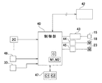
図4はプリンタ1の制御系を示す概略ブロック図である。プリンタ1の制御系は、CP
U、ROM、RAMなどを備えた制御部40を中心に構成されている。制御部40には、
図示しない送受信部を介して、ホスト装置42などの上位機器から印刷データやコマンド
などが供給される。制御部40は、ホスト装置42などからの印刷指令に基づき、ロール
紙9、ファンフォールド紙10を送り出す紙送り動作、キャリッジ16によりインクジェ
ットヘッド15を紙幅方向に往復移動させて印刷を行う印刷動作などを制御する。
(Control system)
FIG. 4 is a schematic block diagram showing a control system of the
The
Print data, commands, and the like are supplied from a host device such as the
制御部40の出力側には、ヘッドドライバ43を介してインクジェットヘッド15が接
続されており、また、モータドライバ44、45を介してキャリッジモータ18、紙送り
モータ23が接続されている。制御部40の入力側には、開閉センサ2cなどのセンサ群
が接続されている。また、エンコーダセンサ46および紙幅センサ33が接続されている
。エンコーダセンサ46はキャリッジ16の移動位置を検出するためのものである。
The
キャリッジ16を紙幅方向に移動させながら、紙幅センサ33により第1、第2給紙経
路A、Bにセットされている記録紙9aあるいはファンフォールド紙10の紙幅の検出が
行なわれる。すなわち、紙幅センサ33の検出出力を所定の閾値と比較することにより、
所定の閾値以上の反射率の変化点を検出し、検出した反射率の変化点の位置をエンコーダ
センサ46の出力に基づいて把握することにより、記録紙9a、ファンフォールド紙10
の幅方向の両側の第1紙端位置P1および第2紙端位置P2を検出する。これら第1、第
2紙端位置は、例えば、キャリッジ16の紙幅方向におけるホームポジションからの距離
として算出され、これらの値に基づき紙幅が算出される。
While moving the
By detecting a change point of the reflectance that is equal to or greater than a predetermined threshold and grasping the position of the detected change point of the reflectance based on the output of the
The first paper edge position P1 and the second paper edge position P2 on both sides in the width direction are detected. These first and second paper edge positions are calculated as distances from the home position in the paper width direction of the
また、制御部40には、予め、インクジェットヘッド15による印刷基準位置を表す紙
幅方向の中央位置がセットされており、この設定中央位置Cに基づき、インクジェットヘ
ッド15による印刷開始位置および印刷終了位置を設定して、印刷を制御する。
In addition, a central position in the paper width direction representing a reference printing position by the
さらに、制御部40には不揮発性メモリからなる記憶部47が接続されている。この記
憶部47には、ロール紙9から繰り出される記録紙9aを搬送する第1給紙経路Aによっ
て規定される記録紙9aの中央位置を補正するための第1位置補正値C1が記憶保持され
ている。換言すると、可動ガイド7a、7bによって規定される紙幅中央位置と、制御部
40にセットされている設定中央位置とのズレ量が、第1位置補正値C1として記憶保持
されている。同様に、記憶部47には、ファンフォールド紙10を搬送する第2給紙経路
Bによって規定されるファンフォールド紙10の中央位置を補正するための第2位置補正
値C2が記憶保持されている。換言すると、可動ガイド29a、29bによって規定され
る紙幅中央位置と設定中央位置とのズレ量が、第2位置補正値C2として記憶保持されて
いる。
Further, a
これらの第1、第2位置補正値C1、C2は、プリンタ1の出荷前の段階において、実
際に記録紙9aおよびファンフォールド紙10を搬送してインクジェットヘッド15によ
って印刷を行い、印刷された部分の中心(設定中央位置)と、各紙幅中央位置とのズレ量
を実測することにより得られたものである。したがって、プリンタ1の個体差に起因する
第1、第2給紙経路A、Bの紙幅方向の位置ズレが反映された値である。
These first and second position correction values C1 and C2 are printed by the
ここで、本例のプリンタ1では、出荷前の段階において、ロール紙9を用いて印刷を行
うロール紙プリンタとして用いるのか、ファンフォールド紙10を用いて印刷を行うプリ
ンタであるのかを択一的に設定するようになっている。ロール紙プリンタとして使用する
場合には、ファンフォールド紙10を挿入するための導入部29などを構成する部品が取
り外され、制御部40にはロール紙モード(第1給紙モード)M1である旨がセットされ
る。ファンフォールド紙10を用いるプリンタとして使用する場合には、ロール紙収納部
7の開閉カバー3を封鎖状態にロックしている不図示のロック機構の解除が不能に設定さ
れ、制御部40にはファンフォールド紙モード(第2給紙モード)M2である旨がセット
される。
Here, in the
(印刷制御動作)
図5ないし図9を参照してプリンタ1の印刷制御動作における主要部分を説明する。ま
ず、図5(a)はプリンタ1の電源投入処理における処理動作を示すフローチャートであ
る。電源投入時には各種の公知の初期化処理と共に、制御部40は、プリンタ1の給紙モ
ードがロール紙モードM1およびファンフォールド紙モードM2のいずれであるのかを確
認する(ステップS1)。ロール紙モードM1がセットされている場合には記憶部47に
記憶保持されている第1位置補正値C1を読み出し、RAM内の作業用記憶領域に保持す
る(ステップS2)。ファンフォールド紙モードM2がセットされている場合には記憶部
47に記憶保持されている第2位置補正値C2を読み出し、RAM内の作業用記憶領域に
保持する(ステップS3)。
(Print control operation)
The main part in the print control operation of the
次に、図5(b)は電源投入時の初期化処理などとして行われる紙幅検出処理を示すフ
ローチャートである。制御部40は、電源投入時、開閉カバー3が閉じされたことを開閉
センサ2cによって検出したとき、紙挿入検出器31によってファンフォールド紙10の
挿入が検出されたとき、などの予め設定した事象が発生した場合に(ステップS11)、
キャリッジ16を駆動してそのホームポジションから紙幅方向の他方の端(アウエイポジ
ション)まで移動させ(ステップS12)、紙幅センサ33を用いて、セットされている
記録紙(記録紙9a、ファンフォールド紙10)の紙幅を検出する(ステップS13)。
これにより、ホームポジションHから、セットされている記録紙のホームポジション側の
第1紙端位置P1およびアウエイポジション側の第2紙端位置P2までのそれぞれの距離
を算出し、これに基づき紙幅を算出する(ステップS14)。
Next, FIG. 5B is a flowchart showing a paper width detection process performed as an initialization process when the power is turned on. When the power is turned on, the
The
Thus, the distances from the home position H to the first paper end position P1 on the home position side and the second paper end position P2 on the away position side of the loaded recording paper are calculated, and the paper width is calculated based on this. Calculate (step S14).
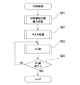
図6は印刷処理動作のフローチャートである。制御部40は、ホスト装置42の側から
印刷データを受信すると印刷処理動作を開始する。まず、印刷開始位置算出処理を行い(
ステップS21)、次に紙幅方向のマスク処理を行い(ステップS22)、しかる後に、
紙送り動作および印刷動作を行い(ステップS23)、印刷終了を検出すると(ステップ
S24)印刷処理を終了する。
FIG. 6 is a flowchart of the print processing operation. The
Step S21), then, a masking process in the paper width direction is performed (Step S22).
The paper feeding operation and the printing operation are performed (step S23), and when the end of printing is detected (step S24), the printing process is terminated.
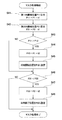
図7(a)は図6の印刷開始位置算出処理(ステップS21)を示すフローチャートで
あり、図7(b)、(c)はその説明図である。印刷開始位置算出処理においては、まず
、設定中央位置Cに、モードM1、M2に応じて読み出された第1位置補正値C1あるい
は第2位置補正値C2を加算して設定中央位置Cを補正する(ステップS31)。これに
より得られた補正設定中央位置Caと、印刷データによって指定されている指定紙幅とに
基づき、印刷開始位置P12(第1印刷端位置)を算出する(ステップS32)。
FIG. 7A is a flowchart showing the print start position calculation process (step S21) in FIG. 6, and FIGS. 7B and 7C are explanatory diagrams thereof. In the print start position calculation process, first, the set center position C is corrected by adding the first position correction value C1 or the second position correction value C2 read according to the modes M1 and M2 to the set center position C. (Step S31). The print start position P12 (first print end position) is calculated based on the correction setting center position Ca obtained in this way and the designated paper width designated by the print data (step S32).
このように印刷開始位置を補正することによって、図7(b)に示すように、個体誤差
に起因して第1給紙経路Aあるいは第2給紙経路Bに発生する紙幅方向のズレを補正して
、記録紙50(記録紙9a、ファンフォールド紙10)の紙幅方向における補正中央位置
Caを基準として所定幅の印刷(図の斜線で示す部分)を行うことが可能になる。このよ
うなズレを補正しない場合には、図7(c)に示すように、実際の印刷開始位置が例えば
ホームポジション側にずれてしまう。記録紙50が長尺状の台紙51に、それよりも狭い
幅のラベル52が貼り付けられているラベル用紙の場合には、ラベル52から横方向に外
れた台紙51の部分に印刷が行われてしまい、プリンタ搬送経路、操作者の手や衣服がイ
ンクで汚れるおそれがある。また、記録紙50から外れた位置に印刷が行われると、記録
紙50の印刷位置を規定しているプラテン表面8aにインクが付着して、後続の記録紙5
0の部分がインクで汚れるなどの不具合が発生する。本例のプリンタ1では紙幅方向のズ
レを補正しているので、このような弊害を回避できる。
By correcting the print start position in this way, as shown in FIG. 7B, the deviation in the paper width direction that occurs in the first paper feed path A or the second paper feed path B due to the individual error is corrected. Thus, it is possible to perform printing (a portion indicated by hatching in the drawing) having a predetermined width with reference to the correction center position Ca in the paper width direction of the recording paper 50 (
Problems such as the 0 portion being stained with ink occur. Since the
図8は印刷位置補正処理の次に行われる紙幅方向のマスク処理(図6のステップS22
)を示すフローチャートであり、図9はその説明図である。まず、検出されてRAMの作
業領域に記憶保持されている記録紙のホームポジション側の第1紙端位置P1および反対
側の第2紙端位置P2に対して記録紙幅方向の内側に第1寸法t1だけ移動した第1内側
端位置P11および第2内側端位置P21を算出する。例えば、ホームポジションHの位
置を基準として、第1紙端位置P1に1mmを加算して第1内側位置P11を算出し(ス
テップS41)、第2紙端位置P2から1mmを減算して第2内側位置P21を算出する
(ステップS42)。
FIG. 8 shows a mask process in the paper width direction that is performed after the print position correction process (step S22 in FIG. 6).
) And FIG. 9 is an explanatory diagram thereof. First, the first dimension inward in the recording paper width direction with respect to the first paper edge position P1 on the home position side and the second paper edge position P2 on the opposite side of the recording paper detected and stored in the work area of the RAM. A first inner end position P11 and a second inner end position P21 moved by t1 are calculated. For example, on the basis of the position of the home position H, 1 mm is added to the first paper edge position P1 to calculate the first inner position P11 (step S41), and 1 mm is subtracted from the second paper edge position P2 to obtain the second The inner position P21 is calculated (step S42).
次に、印刷データから算出した印刷幅を規定する印刷開始位置(第1印刷端位置)P1
2と、第1内側端位置P11を比較し、印刷開始位置P12が第1内側端位置P11と同
一の位置、あるいは、それよりも記録紙幅方向の内側にある場合には当該印刷開始位置P
12を、そのまま印刷開始位置に設定する(ステップS43からNOの流れ)。すなわち
、印刷データの印刷幅が、実際のセットされている記録紙の紙幅以下の場合にはマスク処
理を行わない。
Next, a print start position (first print end position) P1 that defines the print width calculated from the print data
2 is compared with the first inner end position P11, and if the print start position P12 is the same position as the first inner end position P11 or inside the recording paper width direction, the print start position P11 is compared.
12 is set as the printing start position as it is (NO from step S43). That is, the mask process is not performed when the print width of the print data is equal to or smaller than the paper width of the actually set recording paper.
これに対して、印刷開始位置P12が第1内側端位置P11よりも外側にある場合(P
11>P12)には、第1紙端位置P1から第1の寸法(1mm)よりも大きな第2の寸
法だけ記録紙幅方向の内側に移動した位置を印刷開始位置P13と定める(ステップS4
4、S45)。例えば、第1紙端位置P1に3mm加算した位置P13を印刷開始位置と
して定める。
On the other hand, when the print start position P12 is outside the first inner end position P11 (P
11> P12), a position moved from the first paper edge position P1 to the inside in the recording paper width direction by a second dimension larger than the first dimension (1 mm) is defined as a printing start position P13 (step S4).
4, S45). For example, a position P13 obtained by adding 3 mm to the first paper edge position P1 is determined as the print start position.
同様にして、印刷データの印刷幅を規定する印刷終了位置(第2印刷端位置)P22が
第2内側端位P21と同一位置、あるいは、それよりも記録紙幅方向の内側にある場合に
は、指定印刷終了位置P22をそのまま印刷終了位置に設定し(ステップS46からNO
の流れ)、マスク処理は行わない。
Similarly, when the print end position (second print end position) P22 that defines the print width of the print data is at the same position as the second inner end position P21 or inside the recording paper width direction, The designated print end position P22 is set as the print end position as it is (NO from step S46).
), Mask processing is not performed.
これに対して、印刷終了位置P22が第2内側端位置P21よりも外側にある場合(P
21<P22)には、第2紙端位置P2から第2寸法t2(例えば、3mm)だけ記録紙
幅方向の内側に移動した位置P23を算出し、この位置を印刷終了位置に設定する(ステ
ップS47、S48)。
On the other hand, when the print end position P22 is outside the second inner end position P21 (P
21 <P22), a position P23 that is moved inward in the recording paper width direction by the second dimension t2 (for example, 3 mm) from the second paper edge position P2 is calculated, and this position is set as the print end position (step S47). , S48).
このように、印刷データの印刷幅が実際にセットされている記録紙の紙幅以下の場合に
は、マスク処理が行われることなく、印刷データがそのまま印刷される。そうでない場合
には、印刷可能範囲が、印刷データの印刷幅よりも狭い範囲(P13〜P23)に設定さ
れる。
As described above, when the print width of the print data is equal to or smaller than the paper width of the recording paper that is actually set, the print data is printed as it is without performing mask processing. Otherwise, the printable range is set to a range (P13 to P23) narrower than the print width of the print data.
例えば、図9に示すように、ラベル用紙(50)に印刷を行う場合に、印刷データの印
刷幅の印刷開始位置P12および印刷終了位置P22がラベル用紙(50)の紙幅よりも
広い場合には、マスク処理が行われて、印刷される範囲は、印刷開始位置P13から印刷
終了位置P23までの範囲となり、印刷データDのうち両側にはみ出している印刷データ
部分DA、DCは印刷されない。
For example, as shown in FIG. 9, when printing is performed on the label paper (50), if the print start position P12 and the print end position P22 of the print width of the print data are wider than the paper width of the label paper (50). The range to be printed after the mask process is performed is the range from the print start position P13 to the print end position P23, and the print data portions DA and DC protruding from both sides of the print data D are not printed.
このように、印刷データの印刷幅を規定する印刷開始位置および印刷終了位置が、検出
誤差を考慮して設定した第1、第2内側端位置P11、P21よりも外側にある場合には
、検出された第1、第2紙幅位置P1、P2から内側に第1寸法t1より大きな第2寸法
t2(3mm)だけ移動した位置の間が印刷可能な範囲に設定される。したがって、第2
寸法t2を、例えば、使用するラベル用紙(50)における台紙51の端からラベル52
の端までの間の幅寸法よりも大きな値に設定しておくことにより、印刷がラベル52から
外れた台紙51の端の部分に行なわれてしまうことを確実に防止できる。
As described above, when the print start position and the print end position that define the print width of the print data are outside the first and second inner end positions P11 and P21 set in consideration of the detection error, the detection is performed. A printable range is set between the positions moved by the second dimension t2 (3 mm) larger than the first dimension t1 inward from the first and second paper width positions P1 and P2. Therefore, the second
For example, the dimension t2 is changed from the end of the
By setting it to a value larger than the width dimension up to the end of the sheet, it is possible to reliably prevent printing from being performed on the end portion of the
(その他の実施の形態)
上記の実施の形態では、記録紙の幅方向の位置決めを中央基準によって行なっている。
片側基準によって記録紙の幅方向の位置決めを行なうプリンタについても、本発明を同様
に適用できることは勿論である。
(Other embodiments)
In the above embodiment, the recording paper is positioned in the width direction based on the central reference.
Of course, the present invention can be similarly applied to a printer that performs positioning in the width direction of a recording sheet based on one-side reference.
また、上記の実施の形態では、ロール紙およびファンフォールド紙を択一的に使用する
形式のプリンタについて説明したが、これ以外の種類の記録紙に印刷を行うプリンタに対
しても本発明を同様に適用可能である。
Further, in the above-described embodiment, a printer of a type that alternatively uses roll paper and fanfold paper has been described. However, the present invention is similarly applied to a printer that performs printing on other types of recording paper. It is applicable to.
1 プリンタ、2 プリンタ本体、2a 外装ケース、2b 開口部、2c 開閉センサ
、3 開閉カバー、3a カバーケース、4 記録紙排出口、5 排紙ガイド、6 開閉
レバー、7 ロール紙収納部、7a,7b 可動ガイド、8 吸引プラテン、8a プラ
テン表面、9 ロール紙、9a 記録紙、10 ファンフォールド紙、11 記録紙挿入
口、15 インクジェットヘッド、15a インクノズル面、16 キャリッジ、17
キャリッジガイド軸、18 キャリッジモータ、19 タイミングベルト、20 オート
カッタ、21 送り出しローラ、22 紙押さえローラ、23 紙送りモータ、24 前
側紙押さえローラ、25 ロール紙押さえレバー、26 ロール紙押さえローラ、27
テンションガイド、28 後側紙押さえローラ、29 導入路、29a,29b 可動ガ
イド、30 ファンフォールド紙ホルダ、31 紙挿入検出器、33 紙幅センサ、40
制御部、42 ホスト装置、43 ヘッドドライバ、44,45 ドライバ、46 エ
ンコーダセンサ、47 記憶部、P1 第1紙端位置、P2 第2紙端位置、P11 第
1内側端位置、P21 第2内側端位置、P12 指定印刷開始位置(第1指定印刷端位
置)、P22 指定印刷終了位置(第2指定印刷端位置)、P13 印刷開始位置、P2
3 印刷終了位置、t1 第1寸法、t2 第2寸法、H ホームポジション
DESCRIPTION OF
Carriage guide shaft, 18 Carriage motor, 19 Timing belt, 20 Auto cutter, 21 Feeding roller, 22 Paper pressing roller, 23 Paper feeding motor, 24 Front paper pressing roller, 25 Roll paper pressing lever, 26 Roll paper pressing roller, 27
Tension guide, 28 Rear paper pressing roller, 29 Introduction path, 29a, 29b Movable guide, 30 Fanfold paper holder, 31 Paper insertion detector, 33 Paper width sensor, 40
Control unit, 42 Host device, 43 Head driver, 44, 45 driver, 46 Encoder sensor, 47 Storage unit, P1 First paper edge position, P2 Second paper edge position, P11 First inner edge position, P21 Second inner edge Position, P12 designated print start position (first designated print end position), P22 designated print end position (second designated print end position), P13 print start position, P2
3 Print end position, t1 first dimension, t2 second dimension, H home position
Claims (10)
前記第1給紙経路により供給される前記記録紙に対し前記印刷ヘッドの記録紙幅方向の印刷基準位置を補正するための第1位置補正値を記憶しておき、 Storing a first position correction value for correcting a print reference position of the print head in the recording sheet width direction with respect to the recording sheet supplied by the first sheet feeding path;
前記第1位置補正値を読み出して前記印刷基準位置を補正して補正印刷基準位置とし、 Reading out the first position correction value and correcting the print reference position as a corrected print reference position;
前記上位機器から印刷データを受信すると、前記印刷データと前記補正印刷基準位置とに基づき、前記印刷データを印刷するときの印刷幅の記録紙幅方向の一方の端である第1印刷端位置と他方の端である第2印刷端位置を算出し、 When print data is received from the host device, the first print end position which is one end in the recording paper width direction of the print width when printing the print data and the other based on the print data and the corrected print reference position 2nd printing edge position which is the edge of
紙幅検出器を用いて、ホームポジションを基準として、前記第1給紙経路により供給される前記記録紙の一方の端である第1紙端位置および他方の端である第2紙端位置を検出し、 Using a paper width detector, a first paper end position that is one end of the recording paper supplied by the first paper feed path and a second paper end position that is the other end are detected based on the home position. And
前記第1紙端位置および前記第2紙端位置に対して前記記録紙の記録紙幅方向の中央側に向かって第1寸法だけ移動した第1内側端位置および第2内側端位置を算出し、 Calculating a first inner edge position and a second inner edge position which are moved by a first dimension toward the center side in the recording paper width direction of the recording paper with respect to the first paper edge position and the second paper edge position;
前記第1印刷端位置が前記第1内側端位置よりも記録紙幅方向の外側にある場合には、前記第1紙端位置から前記第1寸法より大きな第2寸法だけ前記記録紙の記録紙幅方向の中央側に向かって移動した位置を算出し、当該位置から前記第1印刷端位置までの範囲に印刷されるべき前記印刷データの部分を、印刷しないようにマスク処理し、 When the first printing end position is outside the first inner end position in the recording sheet width direction, the recording sheet width direction of the recording sheet is larger by the second dimension than the first dimension from the first sheet end position. Calculating the position moved toward the center of the image, masking the portion of the print data to be printed in a range from the position to the first print end position so as not to print,
前記第2印刷端位置が前記第2内側端位置よりも記録紙幅方向の外側にある場合には、前記第2紙端位置から前記第2寸法だけ記録紙幅方向の前記記録紙の中央側に向かって移動した位置を算出し、当該位置から前記第2印刷端位置までの範囲に印刷されるべき前記印刷データの部分を、印刷しないようにマスク処理することを特徴とするプリンタの印刷位置制御方法。 When the second print end position is outside the second inner end position in the recording paper width direction, the second print end position is directed from the second paper end position to the center side of the recording paper in the recording paper width direction by the second dimension. A printing position control method for a printer, wherein the position of the print data is calculated, and a portion of the print data to be printed in a range from the position to the second printing end position is masked so as not to be printed .
前記第2給紙経路により供給される前記記録紙に対し前記印刷ヘッドの記録紙幅方向の印刷基準位置を補正するための第2位置補正値を記憶しておき、 Storing a second position correction value for correcting the print reference position of the print head in the recording paper width direction with respect to the recording paper supplied by the second paper feed path;
電源投入時に、前記第1給紙経路から前記記録紙が供給される第1給紙モードおよび前記第2給紙経路から前記記録紙が供給される第2給紙モードのいずれが設定されているのかを判別し、 Either a first paper supply mode in which the recording paper is supplied from the first paper supply path or a second paper supply mode in which the recording paper is supplied from the second paper supply path when the power is turned on is set. To determine whether
前記上位機器から印刷データを受信すると、記憶されている前記第1位置補正値および前記第2位置補正値のうち判別された給紙モードに対応する位置補正値を読み出し、前記印刷基準位置を前記補正印刷基準位置に補正することを特徴とする請求項1に記載のプリンタの印刷位置制御方法。 When print data is received from the host device, a position correction value corresponding to the determined paper feed mode is read out of the stored first position correction value and second position correction value, and the print reference position is set as the print reference position. 2. The printing position control method for a printer according to claim 1, wherein the printing position is corrected to a corrected printing reference position.
前記紙幅検出器による前記記録紙の紙幅検出を、少なくとも、前記開閉カバーが閉じたことが検出された時点、および、前記手差し口に前記ファンフォールド紙が挿入されたことが検出された時点のいずれかにおいて行なうことを特徴とする請求項2ないし4のうちのいずれかの項に記載のプリンタの印刷位置制御方法。 The paper width detection of the recording paper by the paper width detector is at least either when the opening / closing cover is detected to be closed or when the fanfold paper is detected to be inserted into the manual feed slot. 5. The printing position control method for a printer according to claim 2, wherein the printing position control method is performed in the above.
記録紙幅方向へ移動しながら記録紙に印刷する印刷ヘッドと、 A print head for printing on recording paper while moving in the recording paper width direction;
前記記録紙を供給する第1給紙経路と、 A first paper feed path for feeding the recording paper;
前記記録紙の紙幅を検出する紙幅検出器と、 A paper width detector for detecting the paper width of the recording paper;
前記第1給紙経路により供給される前記記録紙に対し、前記印刷ヘッドの記録紙幅方向の印刷基準位置を補正するための第1位置補正値を記憶する記憶部と、 A storage unit for storing a first position correction value for correcting a print reference position of the print head in the recording sheet width direction with respect to the recording sheet supplied by the first sheet feeding path;
前記印刷ヘッドによる印刷動作を制御する制御手段と、を備え、 Control means for controlling a printing operation by the print head,
前記制御手段は、 The control means includes
前記第1位置補正値を読み出して前記印刷基準位置を補正して補正印刷基準位置とし、 Reading out the first position correction value and correcting the print reference position as a corrected print reference position;
前記上位機器から印刷データを受信すると、前記印刷データと前記補正印刷基準位置とに基づき、前記印刷データを印刷するときの印刷幅の記録紙幅方向の一方の端である第1印刷端位置と他方の端である第2印刷端位置を算出し、 When print data is received from the host device, the first print end position which is one end in the recording paper width direction of the print width when printing the print data and the other based on the print data and the corrected print reference position 2nd printing edge position which is the edge of
前記紙幅検出器を用いて、ホームポジションを基準として、前記第1給紙経路により供給される前記記録紙の一方の端である第1紙端位置および他方の端である第2紙端位置を検出し、 Using the paper width detector, a first paper end position which is one end of the recording paper supplied by the first paper feed path and a second paper end position which is the other end of the recording paper supplied from the home position are used as a reference. Detect
前記第1紙端位置および前記第2紙端位置に対して前記記録紙の記録紙幅方向の中央側に向かって第1寸法だけ移動した第1内側端位置および第2内側端位置を算出し、 Calculating a first inner edge position and a second inner edge position which are moved by a first dimension toward the center side in the recording paper width direction of the recording paper with respect to the first paper edge position and the second paper edge position;
前記第1印刷端位置が前記第1内側端位置よりも記録紙幅方向の外側にある場合には、前記第1紙端位置から前記第1寸法より大きな第2寸法だけ前記記録紙の記録紙幅方向の中央側に向かって移動した位置を算出し、当該位置から前記第1印刷端位置までの範囲に印刷されるべき前記印刷データの部分を、印刷しないようにマスク処理し、 When the first printing end position is outside the first inner end position in the recording sheet width direction, the recording sheet width direction of the recording sheet is larger by the second dimension than the first dimension from the first sheet end position. Calculating the position moved toward the center of the image, masking the portion of the print data to be printed in a range from the position to the first print end position so as not to print,
前記第2印刷端位置が前記第2内側端位置よりも記録紙幅方向の外側にある場合には、前記第2紙端位置から前記第2寸法だけ記録紙幅方向の前記記録紙の中央側に向かって移動した位置を算出し、当該位置から前記第2印刷端位置までの範囲に印刷されるべき前記印刷データの部分を、印刷しないようにマスク処理することを特徴とするプリンタ。 When the second print end position is outside the second inner end position in the recording paper width direction, the second print end position is directed from the second paper end position to the center side of the recording paper in the recording paper width direction by the second dimension. A printer that calculates the moved position and masks the portion of the print data to be printed in a range from the position to the second print end position so as not to print.
前記記憶部は、前記第2給紙経路により供給される前記記録紙に対し前記印刷ヘッドによる記録紙幅方向の印刷基準位置を補正するための第2位置補正値を記憶し、 The storage unit stores a second position correction value for correcting a print reference position in a recording sheet width direction by the print head with respect to the recording sheet supplied by the second sheet feeding path.
前記制御手段は、 The control means includes
電源投入時に、前記設定手段が前記第1給紙モードおよび前記第2給紙モードのいずれが設定されているのかを判別し、 When the power is turned on, the setting means determines which of the first paper feed mode and the second paper feed mode is set,
前記上位機器から印刷データを受信すると、前記記憶部に記憶されている前記第1位置補正値および前記第2位置補正値のうち判別された給紙モードに対応する位置補正値を読み出し、前記印刷基準位置を前記補正印刷基準位置に補正することを特徴とする請求項6に記載のプリンタ。 When print data is received from the host device, a position correction value corresponding to the determined paper feed mode is read from the first position correction value and the second position correction value stored in the storage unit, and the print The printer according to claim 6, wherein a reference position is corrected to the corrected printing reference position.
前記マスク処理に当たっては、前記紙幅検出器による検出誤差に基づき、検出された前記紙幅よりも狭い紙幅とすることを特徴とする請求項6または7に記載のプリンタ。 8. The printer according to claim 6, wherein, in the masking process, the paper width is narrower than the detected paper width based on a detection error by the paper width detector. 9.
前記開閉カバーの開閉を検出するカバー検出器と、 A cover detector for detecting opening and closing of the opening and closing cover;
前記第2給紙経路側に備えられる手差し口と、 A manual feed opening provided on the second paper feed path side;
前記手差し口に前記ファンフォールド紙が挿入されたことが検出する挿入検出器と、を有し、 An insertion detector that detects that the fanfold paper has been inserted into the manual feed port, and
前記第1給紙経路から供給される記録紙は、前記ロール紙収納部に収納されたロール紙から繰り出される記録紙であり、 The recording paper supplied from the first paper feed path is a recording paper fed out from the roll paper stored in the roll paper storage unit,
前記第2給紙経路から供給される記録紙は、手差し口から挿入される前記ファンフォールド紙であり、 The recording paper supplied from the second paper feed path is the fanfold paper inserted from the manual feed port,
前記紙幅検出器による前記記録紙の紙幅検出を、少なくとも、前記カバー検出器が前記開閉カバーが閉じたことを検出した時点、および、前記挿入検出器が前記手差し口に前記ファンフォールド紙が挿入されたことを検出した時点の、いずれかにおいて行なうことを特徴とする請求項7ないし9のうちのいずれかの項に記載のプリンタ。 The paper width detection of the recording paper by the paper width detector is performed at least when the cover detector detects that the opening / closing cover is closed, and the insertion detector inserts the fanfold paper into the manual feed port. The printer according to any one of claims 7 to 9, wherein the printer is performed at any time when it is detected.
Priority Applications (1)
| Application Number | Priority Date | Filing Date | Title |
|---|---|---|---|
| JP2008195874A JP5146175B2 (en) | 2008-07-30 | 2008-07-30 | Printer printing position control method and printer |
Applications Claiming Priority (1)
| Application Number | Priority Date | Filing Date | Title |
|---|---|---|---|
| JP2008195874A JP5146175B2 (en) | 2008-07-30 | 2008-07-30 | Printer printing position control method and printer |
Publications (3)
| Publication Number | Publication Date |
|---|---|
| JP2010030187A JP2010030187A (en) | 2010-02-12 |
| JP2010030187A5 JP2010030187A5 (en) | 2011-05-26 |
| JP5146175B2 true JP5146175B2 (en) | 2013-02-20 |
Family
ID=41735270
Family Applications (1)
| Application Number | Title | Priority Date | Filing Date |
|---|---|---|---|
| JP2008195874A Expired - Fee Related JP5146175B2 (en) | 2008-07-30 | 2008-07-30 | Printer printing position control method and printer |
Country Status (1)
| Country | Link |
|---|---|
| JP (1) | JP5146175B2 (en) |
Cited By (1)
| Publication number | Priority date | Publication date | Assignee | Title |
|---|---|---|---|---|
| US11459199B2 (en) | 2018-12-28 | 2022-10-04 | Brother Kogyo Kabushiki Kaisha | Printing apparatus |
Families Citing this family (4)
| Publication number | Priority date | Publication date | Assignee | Title |
|---|---|---|---|---|
| JP6217626B2 (en) * | 2014-12-26 | 2017-10-25 | コニカミノルタ株式会社 | Image forming apparatus |
| JP6469456B2 (en) * | 2015-01-21 | 2019-02-13 | 株式会社沖データ | Image forming apparatus, image forming method, and image forming program |
| JP2018058342A (en) * | 2016-09-29 | 2018-04-12 | 株式会社日立ハイテクファインシステムズ | Printer and printing method |
| JP6624039B2 (en) * | 2016-12-15 | 2019-12-25 | 京セラドキュメントソリューションズ株式会社 | Inkjet recording device |
-
2008
- 2008-07-30 JP JP2008195874A patent/JP5146175B2/en not_active Expired - Fee Related
Cited By (1)
| Publication number | Priority date | Publication date | Assignee | Title |
|---|---|---|---|---|
| US11459199B2 (en) | 2018-12-28 | 2022-10-04 | Brother Kogyo Kabushiki Kaisha | Printing apparatus |
Also Published As
| Publication number | Publication date |
|---|---|
| JP2010030187A (en) | 2010-02-12 |
Similar Documents
| Publication | Publication Date | Title |
|---|---|---|
| JP5562182B2 (en) | Image recording apparatus and control method thereof | |
| JP5146175B2 (en) | Printer printing position control method and printer | |
| US8696084B2 (en) | Method of controlling printing in a printer, and a printer | |
| JP4578253B2 (en) | Recording device | |
| JP4736909B2 (en) | Printer and printer control method | |
| US8646996B2 (en) | Method of setting paper in a printer, and a printer | |
| US8711389B2 (en) | Printing control method and printer for printing on a label | |
| JP4517926B2 (en) | Printer recording paper loading method | |
| JP2003211796A (en) | Image recording medium and image recording apparatus using the same | |
| JP2010030188A (en) | Printing position control method of printer and printer | |
| US20050163552A1 (en) | Printing method and image forming apparatus for performing the same | |
| JP2010030190A (en) | Positioning method of recording paper and printer | |
| JP7298310B2 (en) | PRINTING DEVICE AND METHOD OF CONTROLLING PRINTING DEVICE | |
| JP5609999B2 (en) | Printer reprint control method and printer | |
| JP2010023386A (en) | Method for cutting recording paper in printer and printer | |
| JP2010023387A (en) | Method for cutting recording paper in printer and printer | |
| JP2000037915A (en) | Recorder | |
| JP5556912B2 (en) | Print control method in printer and printer | |
| JP2017088327A (en) | Printer and control method | |
| US20200164667A1 (en) | Printer with cutting head | |
| JP2010030189A (en) | Method for detecting faulty arrangement of recording paper and serial printer | |
| JP2022127044A (en) | Sheet detection device | |
| JP4839916B2 (en) | Image recording device | |
| JP5195134B2 (en) | Recording paper autoloading method and printer | |
| JP2013163330A (en) | Method for correcting warpage of print sheet of printer, and printer |
Legal Events
| Date | Code | Title | Description |
|---|---|---|---|
| A521 | Request for written amendment filed |
Free format text: JAPANESE INTERMEDIATE CODE: A523 Effective date: 20110407 |
|
| A621 | Written request for application examination |
Free format text: JAPANESE INTERMEDIATE CODE: A621 Effective date: 20110407 |
|
| TRDD | Decision of grant or rejection written | ||
| A977 | Report on retrieval |
Free format text: JAPANESE INTERMEDIATE CODE: A971007 Effective date: 20121024 |
|
| A01 | Written decision to grant a patent or to grant a registration (utility model) |
Free format text: JAPANESE INTERMEDIATE CODE: A01 Effective date: 20121030 |
|
| A61 | First payment of annual fees (during grant procedure) |
Free format text: JAPANESE INTERMEDIATE CODE: A61 Effective date: 20121112 |
|
| R150 | Certificate of patent or registration of utility model |
Ref document number: 5146175 Country of ref document: JP Free format text: JAPANESE INTERMEDIATE CODE: R150 Free format text: JAPANESE INTERMEDIATE CODE: R150 |
|
| FPAY | Renewal fee payment (event date is renewal date of database) |
Free format text: PAYMENT UNTIL: 20151207 Year of fee payment: 3 |
|
| S531 | Written request for registration of change of domicile |
Free format text: JAPANESE INTERMEDIATE CODE: R313531 |
|
| R350 | Written notification of registration of transfer |
Free format text: JAPANESE INTERMEDIATE CODE: R350 |
|
| LAPS | Cancellation because of no payment of annual fees |