JP5145390B2 - System and method for scheduling start-up of a combined cycle power generation system - Google Patents
System and method for scheduling start-up of a combined cycle power generation system Download PDFInfo
- Publication number
- JP5145390B2 JP5145390B2 JP2010198420A JP2010198420A JP5145390B2 JP 5145390 B2 JP5145390 B2 JP 5145390B2 JP 2010198420 A JP2010198420 A JP 2010198420A JP 2010198420 A JP2010198420 A JP 2010198420A JP 5145390 B2 JP5145390 B2 JP 5145390B2
- Authority
- JP
- Japan
- Prior art keywords
- time
- period
- startup
- power generation
- forecast
- Prior art date
- Legal status (The legal status is an assumption and is not a legal conclusion. Google has not performed a legal analysis and makes no representation as to the accuracy of the status listed.)
- Active
Links
Images


Classifications
-
- G—PHYSICS
- G05—CONTROLLING; REGULATING
- G05B—CONTROL OR REGULATING SYSTEMS IN GENERAL; FUNCTIONAL ELEMENTS OF SUCH SYSTEMS; MONITORING OR TESTING ARRANGEMENTS FOR SUCH SYSTEMS OR ELEMENTS
- G05B17/00—Systems involving the use of models or simulators of said systems
- G05B17/02—Systems involving the use of models or simulators of said systems electric
-
- Y—GENERAL TAGGING OF NEW TECHNOLOGICAL DEVELOPMENTS; GENERAL TAGGING OF CROSS-SECTIONAL TECHNOLOGIES SPANNING OVER SEVERAL SECTIONS OF THE IPC; TECHNICAL SUBJECTS COVERED BY FORMER USPC CROSS-REFERENCE ART COLLECTIONS [XRACs] AND DIGESTS
- Y02—TECHNOLOGIES OR APPLICATIONS FOR MITIGATION OR ADAPTATION AGAINST CLIMATE CHANGE
- Y02E—REDUCTION OF GREENHOUSE GAS [GHG] EMISSIONS, RELATED TO ENERGY GENERATION, TRANSMISSION OR DISTRIBUTION
- Y02E20/00—Combustion technologies with mitigation potential
- Y02E20/16—Combined cycle power plant [CCPP], or combined cycle gas turbine [CCGT]
Landscapes
- Physics & Mathematics (AREA)
- General Physics & Mathematics (AREA)
- Engineering & Computer Science (AREA)
- Automation & Control Theory (AREA)
- Control Of Turbines (AREA)
- Engine Equipment That Uses Special Cycles (AREA)
- Control Of Eletrric Generators (AREA)
Description
本発明は、全体的に複合サイクル(CC)発電システムに関し、詳細には、CC発電システム(本明細書では「プラント」とも呼ばれる)の始動のスケジューリングに関する。 The present invention relates generally to combined cycle (CC) power generation systems and, in particular, to scheduling startup of a CC power generation system (also referred to herein as a “plant”).
プラントは、通常、電力設備会社により、又は電力設備会社向けに運転され、最終的には中央卸市場又は調整された発電システムオペレータを介して送電される電力を発生する。電力設備会社は、1つ又はそれ以上のCC発電システム及び他の発電システムから電力を生成することができる。 A plant is typically operated by or for a power equipment company and ultimately generates power that is transmitted through a central wholesale market or a regulated power system operator. A power equipment company can generate power from one or more CC power generation systems and other power generation systems.
電力会社に対する電力需要は、時間毎、日付毎、季節毎、及び年毎に変化する傾向がある。これらの顧客からの電力需要は、例えば、予想される天気、顧客による将来の電力要求、電力需要に影響を及ぼす生起予定の事象など、電力需要及び他の情報に関する履歴データに基づいて、系統オペレータにより予報される。系統オペレータは、予報電力需要を発電所のオペレータ(例えば、電力会社)に助言する。電力需要は変化するので、各プラントで電力設備会社により作成されるスケジュールは、多くの場合、例えば前日など、電力が生成される少し前の時間に確定する。スケジュールが確定すると、発電システムのオペレータは、電力需要が発生することをスケジュールが示したときに、給電可能負荷レベルで電力を提供するようCC発電システム(プラント)を起動させるタイミングを決定する。 Electric power demand for electric power companies tends to change every hour, every day, every season, and every year. The power demand from these customers is based on historical data on power demand and other information, such as expected weather, future power demands by customers, and upcoming events that affect power demand. Predicted by. The grid operator advises the power plant operator (eg, the power company) about the predicted power demand. Since the power demand changes, the schedule created by the power equipment company at each plant is often fixed at a time just before power is generated, such as the previous day. When the schedule is fixed, the operator of the power generation system determines the timing for starting the CC power generation system (plant) to provide power at the loadable load level when the schedule indicates that power demand is generated.
プラント起動のタイミングの決定は、複雑で困難なスケジューリング問題を生じる。始動シーケンスは、オフ状態から、プラントが給電可能負荷レベルで電力を生成する状態にする。始動シーケンスは通常、種々のガスタービン、蒸気タービン、ボイラ、及び蒸気を発生する他のシステム、並びにガス及び蒸気タービンにより駆動される発電機を伴う複雑なスケジュールである。プラントが停止すると、ガスタービンには燃料が提供されておらず、蒸気タービンには蒸気が提供されていない。プラントが停止すると、ガスタービン及び蒸気タービンは、最終作動状態から冷却される。プラントが再起動されると、始動シーケンスの始動期間すなわち始動シーケンスを完了するまでの時間は、始動シーケンスが開始されたときの蒸気タービンの温度に大きく依存する。 The determination of plant start-up timing creates a complex and difficult scheduling problem. The start-up sequence changes from the off state to a state in which the plant generates power at a loadable load level. The startup sequence is typically a complex schedule with various gas turbines, steam turbines, boilers, and other systems that generate steam, and generators driven by the gas and steam turbines. When the plant is shut down, no fuel is provided to the gas turbine and no steam is provided to the steam turbine. When the plant is shut down, the gas turbine and the steam turbine are cooled from the final operating state. When the plant is restarted, the start-up period of the start-up sequence, ie the time to complete the start-up sequence, depends largely on the temperature of the steam turbine when the start-up sequence is started.
始動シーケンスの持続時間を正確に算出するツールを有することは、プラントのオペレータに有用となる。オペレータは通常、プラントが何時給電可能負荷レベルで電力の生成に取りかかるかを認識している。正確な始動持続期間が分かると、オペレータは、プラントが電力の生成に取りかかる直前に給電可能負荷に到達するように、可能な最も遅い時間に最少量の燃料を用いてプラントを起動できるようになる。 Having a tool that accurately calculates the duration of the start-up sequence is useful for plant operators. The operator typically knows when the plant will begin generating power at a loadable load level. Knowing the exact start-up duration will allow the operator to start up the plant with the least amount of fuel at the latest possible time so that the plant will reach a loadable load just before the plant begins to generate power .
始動シーケンスを開始するタイミングを決定するには、システムオペレータが該シーケンスに必要な時間長を推定することが必要となる。CC発電システムについての正確な条件ベース始動スケジュールの算出は、始動シーケンスの持続期間を正確に予報することが困難であることに起因して、従来はシステムオペレータにより手動で実施された厄介で複雑な作業となる可能性がある。プラントオペレータは通常、正確な条件ベース始動スケジュールを算出するのではなく、幾つかの始動条件についての始動期間の事前準備のテンプレートを用いて始動スケジュールを予報する。準備始動テンプレートは、推定期間が適用される始動シーケンスの種類の何れよりも予測始動期間が確実に短くならないように、控えめに長い始動期間を予測する。この予測が控えめであるので、始動期間の準備テンプレートは、始動シーケンスの起動時の蒸気ロータの温度など、幅広い初期条件に一般的に適用することができる。準備テンプレートは、ほとんどの実始動期間よりも有意に長い始動期間を提示することができる。 Determining when to start the startup sequence requires the system operator to estimate the length of time required for the sequence. Accurate condition-based start-up schedule calculations for CC power generation systems are cumbersome and complex, conventionally performed manually by system operators due to the difficulty in accurately predicting the duration of the start-up sequence There is a possibility of work. Rather than calculating an accurate condition-based start schedule, the plant operator typically predicts the start schedule using a template of start-up period for several start conditions. The ready start template predicts a conservatively longer start period to ensure that the predicted start period is not shorter than any of the start sequence types to which the estimated period applies. Since this prediction is conservative, the start-up period preparation template can generally be applied to a wide range of initial conditions, such as the temperature of the steam rotor at start-up of the start-up sequence. The preparation template can present a start-up period that is significantly longer than most actual start-up periods.
既存のスケジュールテンプレートを再利用すると、新規の運転日又は時間期間についての新しい始動スケジュールの準備を効率的に処理できるが、スケジュールテンプレートは、任意の所与の日又は時間期間に対する最適な始動シーケンス及び始動期間をもたらさないことが多い。更に、事前準備スケジュールは、スケジュールを適用できる可能な状況の全てに適合するよう様々な発電構成要素が確実に利用可能となる長い時間マージンを組み込む場合がある。これらの長いマージンは、発電構成要素が必要となるまでに最大で数時間の給電可能負荷が利用可能になり、低負荷レベルで非効率的に燃料を無用に燃焼する結果となる。必要とされるよりも早期に給電可能負荷に到達すると、必要な電力を生成するために電力構成要素が適用されるのを待機している間に該構成要素が作動していることに起因して金銭的損失が生じ、最適未満の価格水準で生成電力が販売される結果となる。 Reusing an existing schedule template can efficiently handle the preparation of a new startup schedule for a new operating day or time period, but the schedule template can be optimized for any given day or time period and Often does not result in a start-up period. In addition, the advance schedule may incorporate a long time margin that ensures that the various power generation components are available to fit all of the possible situations where the schedule can be applied. These long margins allow for up to several hours of powerable load before power generation components are required, resulting in inefficient combustion of fuel at low load levels. If the loadable load is reached sooner than needed, it is due to the component operating while waiting for the power component to be applied to generate the required power. This results in a financial loss that results in the electricity generated being sold at a suboptimal price level.
始動持続期間の推定準備に関する問題は、プラントが給電可能電力を生成するようスケジュールされている30分前又はそれ以上前に、給電可能負荷レベルにプラントが到達する可能性があることである。プラントが、電力を供給するようスケジュールされる前に電力を生成する場合には、該プラントは、燃料を消費し、過剰な熱及びエミッションを発生し、比較的低効率で作動する可能性があり、オペレータは、市場価格未満の価格での電力の販売を余儀なくされる可能性がある。十分な需要もなく給電可能負荷でプラントを運転することは望ましいことではない。周期的デューティ要件が増大し、燃料コストが高くなり、競争の激しい規制緩和されたエネルギー市場及び厳しい環境規制は、CC発電システム運転からのより迅速で予測可能な始動シーケンスに対する需要を創出している。
The problem with preparing for start-up duration estimation is that the plant may reach a
CC発電システムを始動させるために簡単且つ正確にスケジュール及び予報を生成する方法及びシステムについての長年にわたる要求がある。この要求が存在する理由は、幾つかの準備始動スケジュールの1つを選択する従来の手動による手法では、発電構成要素(例えば、ガスタービン及び蒸気タービン)が実際に必要とするよりも数時間前に給電可能負荷レベルに達することに起因して非効率的な結果となるためである。更に、発電プラントが電力を生成しようとしている要件により、始動スケジュールを迅速に生成し、発電コストを低減するよう最適化された正確なスケジューリング及び予報ツールに対する必要性が高くなる。 There is a longstanding need for a method and system for generating schedules and forecasts simply and accurately to start a CC power generation system. The reason for this requirement is that the traditional manual approach of selecting one of several preparatory start-up schedules is several hours before the power generation components (eg, gas turbine and steam turbine) actually need it. This is because an inefficient result is caused by reaching a loadable load level. Furthermore, the requirements that power plants are trying to generate power increase the need for accurate scheduling and forecasting tools that are optimized to quickly generate startup schedules and reduce power generation costs.
CC発電システムを始動するのに必要な時間を短縮することは、システム始動時の考慮事項だけではない。発電システムの所有者は、局所的環境規制、エネルギー送給要件、及び現在の燃料及びエネルギー価格に応じた様々な始動対象物を管理している。発電システムオペレータは、エミッション、燃料コスト、又は正味熱消費率を最小限にすることが必要になる場合がある。これらの考慮事項は、始動運転のタイミングに影響を及ぼすことができる。各CC発電システムは、始動スケジュールに影響を及ぼす現場固有要因を有することができる。CC発電システムの様々な始動運転条件についての始動持続期間を正確に予測する始動スケジュールに対する長年にわたる強い要求がある。 Reducing the time required to start the CC power generation system is not only a consideration at system startup. The owners of the power generation system manage various start-ups depending on local environmental regulations, energy delivery requirements, and current fuel and energy prices. A power generation system operator may need to minimize emissions, fuel costs, or net heat consumption. These considerations can affect the timing of start-up operations. Each CC power generation system can have site specific factors that affect the startup schedule. There is a longstanding need for a start schedule that accurately predicts the start duration for various start operating conditions of a CC power generation system.
ガスタービンエンジン、蒸気タービン、並びにユーザ入力デバイス及び出力デバイスを含むコンピュータ制御システムを備えた複合サイクル発電システムの起動期間を予報する方法は、複合サイクル発電システムが給電可能負荷に到達するようになる所望時間を入力する段階と、複合サイクル発電システムの所定運転条件の現在値を収集する段階と、コンピュータ制御システムが、所望時間及び現在値に基づいて予報起動時間を生成するアルゴリズムを実行し、複合サイクル発電システムが、予報起動時間にて起動されたときの所望時間に給電可能負荷であるよう予測されるようにする段階と、コンピュータシステムが、予報起動時間を出力デバイスに出力する段階と、を含む。 A method for predicting the start-up period of a combined cycle power generation system with a gas turbine engine, a steam turbine, and a computer control system including user input and output devices is desired for the combined cycle power generation system to reach a powerable load. Inputting a time; collecting a current value of a predetermined operating condition of the combined cycle power generation system; and a computer control system executing an algorithm for generating a forecast start time based on the desired time and the current value, Allowing the power generation system to be predicted to be a powerable load at a desired time when activated at a forecast activation time, and the computer system outputting the forecast activation time to an output device. .
ガスタービンエンジン、蒸気タービン、及びコンピュータ制御システムを備えた複合サイクル発電システムの起動期間を予報する方法は、発電システムが給電可能負荷に到達するようになる所望時間を入力する段階と、発電システムの所定運転条件の現在値を入力する段階と、コンピュータ制御システムが、発電システム又は同様の発電システムの以前の起動期間に所定運転条件を関連付けるデータベースからデータを取り出す段階と、コンピュータ制御システムが、所望時間、現在値、及び取り出したデータに基づいて予報起動時間を生成するアルゴリズムを実行し、発電システムが、予報起動時間にて起動されたときの所望時間に給電可能負荷に到達するよう予測されるようにする段階と、コンピュータシステムが、予報起動時間を出力デバイスに出力する段階と、を含む。 A method for predicting the start-up period of a combined cycle power generation system comprising a gas turbine engine, a steam turbine, and a computer control system includes inputting a desired time for the power generation system to reach a loadable load, Inputting a current value of a predetermined operating condition; a computer control system retrieving data from a database that associates the predetermined operating condition with a previous startup period of the power generation system or similar power generation system; and An algorithm for generating a forecast start time based on the current value and the retrieved data is executed so that the power generation system is predicted to reach the power supplyable load at a desired time when started at the forecast start time. And the computer system outputs the forecast startup time Comprising the steps of outputting a vise, a.
ガスタービンエンジン、蒸気タービン、並びにユーザ入力部及び表示装置を有する制御システムを備えた複合サイクル発電システムの起動期間を予報する方法は、現在時間での蒸気タービン温度の現在タービン温度を決定する段階と、現在時間から発電システムが予め定義された出力レベルになる目標時間までの期間として給電可能負荷に対する目標時間期間を決定する段階と、現在時間から発電システムの始動シーケンスの起動時間までの期間として予報起動時間期間を選択する段階と、予報起動時間期間及び現在タービン温度に基づいて、予報起動時間の推定タービン起動温度を決定する段階と、推定タービン起動温度を用いて、始動シーケンスの推定時間期間を決定する段階と、予報起動時間期間と始動シーケンスの推定時間期間とを合計して総時間期間を算出する段階と、第1の時間から目標時間までの目標時間期間と総時間期間とを比較する段階と、推定総時間が目標時間期間の所定期間内にあると該比較により判定された場合、予報起動時間期間を用いて始動シーケンスを起動するタイミングを決定する段階と、推定総時間が目標時間期間の所定期間外にあると比較により示された場合、予報起動時間を減分する段階と、当該方法の各段階を繰り返す段階と、を含む。 A method for predicting the start-up period of a combined cycle power generation system with a gas turbine engine, a steam turbine, and a control system having a user input and a display, determines a current turbine temperature of the steam turbine temperature at a current time, and Determining the target time period for the load that can be fed as the period from the current time to the target time at which the power generation system reaches a predefined output level, and forecasting as the period from the current time to the start time of the start sequence of the power generation system Selecting a startup time period; determining an estimated turbine startup temperature for a predicted startup time based on the predicted startup time period and the current turbine temperature; and using the estimated turbine startup temperature to determine an estimated time period for the startup sequence. The stage to determine, the forecast start-up time period and the estimated start-up time period Calculating the total time period, comparing the target time period from the first time to the target time with the total time period, and when the estimated total time is within a predetermined period of the target time period, If determined by comparison, a stage for determining when to start the start sequence using the forecast activation time period, and if the comparison indicates that the estimated total time is outside the predetermined period of the target time period, the forecast activation time Decrementing and repeating the steps of the method.
ガスタービンエンジン(GT)と、少なくとも1つの蒸気タービン(ST)と、グラフィカルユーザインタフェース(GUI)のユーザ入力部及び表示装置を有するコンピュータを含む制御システムとを備えた複合サイクル発電システムの起動時間を予報する方法は、蒸気タービンの少なくとも1つのうちの最新時間に対応する温度を制御システムに入力する段階と、制御システムが、第1の時間から発電システムが給電可能負荷にあるようにスケジュールされる目標時間までの期間として目標時間期間を決定する段階と、制御システムが、第1の時間から発電システムの始動シーケンスの起動までの期間として予報起動時間期間を選択する段階と、予報起動時間期間及び第1の温度に基づいて、コントローラにより予報起動時間で生じる推定タービン温度を決定する段階と、推定タービン温度に基づいて、コントローラにより始動シーケンスの推定時間期間を決定する段階と、コントローラにより、予報起動時間期間と始動シーケンスの推定時間期間とを合計し、第1の時間から始動シーケンスの終わりまでの推定総時間を生成する段階と、コントローラにより、推定総時間及び目標時間期間を比較する段階と、コントローラが、比較の実施時に推定総時間が目標時間期間の所定期間内にあると判定した場合に、予報起動時間を出力する段階と、コントローラが、推定総時間が目標時間期間の所定期間外にあると判定した場合に、予報起動時間を減分する段階と、本方法を繰り返す段階と、を含む。 A start-up time of a combined cycle power generation system comprising a gas turbine engine (GT), at least one steam turbine (ST), and a control system including a computer having a graphical user interface (GUI) user input and a display. The method of forecasting inputs a temperature corresponding to the latest time of at least one of the steam turbines to the control system, and the control system is scheduled so that the power generation system is in a loadable load from the first time. Determining a target time period as a period up to the target time; selecting a forecast start time period as a period from the first time to starting the power generation system start sequence; a forecast start time period; Based on the first temperature, the controller generates an estimate that occurs at the forecast start-up time. Determining a turbine temperature, determining an estimated start sequence time period by a controller based on the estimated turbine temperature, and adding a predicted start time period and an estimated start sequence time period by the controller; Generating an estimated total time from a predetermined time to the end of the start-up sequence, comparing the estimated total time and the target time period by the controller, and determining whether the estimated total time is a predetermined target time period when performing the comparison. Outputting a forecast activation time when it is determined that the period is within the period; and decrementing the forecast activation time when the controller determines that the estimated total time is outside the predetermined period of the target time period; Repeating the method.
ガスタービン及び蒸気タービンを有する複合サイクル発電システムの予報起動期間を生成するコンピュータ制御システムは、複合サイクル発電システムが給電可能負荷に到達するようになる所望時間と、複合サイクル発電システムの所定運転条件の現在値とを受け取るユーザ入力部と、予報起動時間を出力し、複合サイクル発電システムが予報起動時間にて起動されたときの所望時間に給電可能負荷であるよう予測されるようにする出力デバイスと、プロセッサと、電子メモリと、を備え、当該電子メモリが、所望時間及び現在値を示すデータと、発電システム又は同様の発電システムの起動期間に所定運転条件を関連付ける履歴情報を有するデータベースと、所望時間と、現在値と、データベースから取り出されるデータとに基づいて予報起動時間を生成するアルゴリズムと、を記憶している。 A computer control system that generates a forecast start-up period for a combined cycle power generation system having a gas turbine and a steam turbine is provided for a desired time for the combined cycle power generation system to reach a loadable load and for a predetermined operating condition of the combined cycle power generation system. A user input unit that receives the current value, an output device that outputs a forecast activation time, and that is predicted to be a power supplyable load at a desired time when the combined cycle power generation system is activated at the forecast activation time; and A processor and an electronic memory, the electronic memory having data indicating the desired time and current value, a database having history information associating a predetermined operating condition with a start-up period of a power generation system or a similar power generation system, and a desired Forecast based on time, current value and data retrieved from database Stores the algorithm for generating the dynamic time, the.
ガスタービン及び蒸気タービンを含む複合サイクル発電システムの制御システムは、プロセッサと、以前の始動プロセスのデータベース及び将来の始動プロセスの起動時間をスケジュールするコンピュータプログラムを記憶する電子メモリとを備え、プログラムによって、制御システムに対する入力として蒸気タービンの現在温度を入力する段階と、制御システムが、現在時間から発電システムが給電可能負荷になるようスケジュールされる目標時間までの期間として給電可能負荷期間に対する時間期間を決定する段階と、現在時間から発電システムの始動プロセスの起動時間までの期間として予報起動時間期間を選択する段階と、予報起動時間期間及び蒸気タービンの少なくとも1つのうちの現在温度に基づいて、予報起動時間での推定ロータ温度を決定する段階と、推定ロータ温度に基づいて、予報起動時間に開始され、発電システムが予め定義された給電可能負荷に到達したときに終了する期間である始動プロセスの推定時間期間を決定する段階と、予報起動時間期間と始動プロセスの推定時間期間とを合計し、給電可能負荷までの総時間を生成する段階と、給電可能負荷までの総時間と、現在時間から目標時間までの時間期間とを比較する段階と、比較の実施時に給電可能負荷までの総時間が目標時間までの現在時間の所定期間内にあるとコントローラが判定した場合に、始動プロセスを起動するタイミングを決定する段階と、比較時に給電可能負荷までの総時間が目標時間までの現在時間の所定期間外にあるとコントローラが判定した場合に、所定期間だけ予報起動時間を減分する段階と、本方法を繰り返す段階とを含む処理段階をプロセッサに実施させるようにする。 A control system for a combined cycle power generation system including a gas turbine and a steam turbine comprises a processor and an electronic memory storing a computer program that schedules a database of previous startup processes and a startup time of a future startup process, Entering the current temperature of the steam turbine as input to the control system and determining the time period for the loadable load period as the period from the current time to the target time when the power generation system is scheduled to be loadable Selecting a forecast start-up time period as a period from the current time to the start-up time of the power generation system start-up process, and a forecast start-up based on the forecast start-up time period and the current temperature of at least one of the steam turbines Estimated time in time And the estimated time period of the start-up process, which is the period that starts at the forecast start-up time and ends when the power generation system reaches a predefined loadable load based on the estimated rotor temperature And the estimated start-up time period and the estimated start-up time period to generate a total time until the load can be supplied, and the total time until the load can be supplied and the time from the current time to the target time Comparing the period and determining when to start the start process when the controller determines that the total time to the load that can be fed is within a predetermined period of the current time up to the target time when performing the comparison When the controller determines that the total time until the load that can be supplied is outside the predetermined period of the current time until the target time at the time of comparison, the forecast start time for the predetermined period Comprising the steps of decrementing, the processing step including the steps of repeating the method so as to be performed in the processor.
本発明のこれら及び他の特徴、態様、並びに利点は、図面全体を通じて同様の参照符号が同様の要素を示す添付図面を参照しながら以下の詳細な説明を読むと更に理解できるであろう。 These and other features, aspects, and advantages of the present invention will be better understood when the following detailed description is read with reference to the accompanying drawings in which like reference characters indicate like elements throughout the drawings.
複合サイクル発電システム(プラントとも呼ばれる)のオペレータがプラントの始動プロセスの開始を予測しスケジューリングするのを支援するために、ヒューマン・マシン・インターフェース(HMI)が開発されてきた。HMIは、ソフトウェアスーツ、プラントの蒸気タービン構成要素のソフトウェアベースのモデル、並びにプラント及び類似のプラントの始動に関する履歴情報のデータベースとオペレータが対話できるようになるスクリーン画像を生成する一連の対話型コンピュータシステムとして具現化することができる。HMIは、オペレータ入力、センサデータ、発電システムにおける制御システム内の補助アルゴリズム、及び他の入力から、複合サイクル発電システムの給電可能負荷に達するスケジュール及び現在の運転条件に関する情報を収集することができる。HMI生成スクリーン画像は、オペレータが実施可能な選択肢、及び以下のような複合サイクル発電システムに関する情報を提示する。
(i)プラント構成(例えば、1つのガスタービンと1つの蒸気タービン(1X1)、2つのガスタービンと1つの蒸気タービン(2X1)、3つのガスタービンと1つの蒸気タービン(3X1))
(ii)現在の条件(例えば、蒸気タービンのロータ温度)
(iii)プラントからの給電可能負荷が要求されるまでの残り時間
(iv)プラントの最近の始動運転の始動性能履歴
(v)プラントの始動シーケンスを開始する提案スケジュール及び予報
(vi)蒸気ロータ温度を含む、CC発電システムの動作パラメータの最小値、最大値、及び標準偏差などの統計データ履歴
HMIは、プラントの推定始動条件に基づき始動シーケンスを実施するのに必要な時間期間を推定するツールを提供する。HMIツールは、システムにおける蒸気タービンの初期ロータ温度など、既知の始動条件に基づいて始動シーケンスの期間を算出する。既知の始動条件を決定するために、HMIツールは、プラントの始動シーケンスの時間量を推定する計算を実施し、プラントからの電力需要が生じるようスケジュールされたときに給電可能電力レベルに到達させるために、HMIツールが何時始動シーケンスを開始すべきかを予報できるようにする。HMIスクリーンの出力は、プラントオペレータが、通信指令員、系統オペレータ、又は電力業者により要求される起動時間及び燃料消費量などの入力を容易に伝達できるように提示される。HMIコンピュータシステムの技術的作用は、複合サイクル発電システムにおいて、当該システムが開始できる予報起動時間を生成し、例えば電力網に要求電力を提供する予定時間に給電可能負荷に到達させることである。例えば、予報起動時間により、発電システムは、要求電力を提供する予定時間前の3から5分を超えない時間に給電可能負荷に到達できるようになる。
Human machine interfaces (HMI) have been developed to help operators of combined cycle power systems (also called plants) predict and schedule the start of the plant startup process. HMI is a series of interactive computer systems that generate screen images that allow an operator to interact with a software suit, a software-based model of a plant's steam turbine components, and a database of historical information about the startup of the plant and similar plants. Can be embodied as The HMI can collect information about the schedule and current operating conditions to reach the power load of the combined cycle power system from operator input, sensor data, auxiliary algorithms in the control system in the power system, and other inputs. The HMI generation screen image presents options that the operator can implement and information about the combined cycle power generation system as follows.
(I) Plant configuration (eg, one gas turbine and one steam turbine (1X1), two gas turbines and one steam turbine (2X1), three gas turbines and one steam turbine (3X1))
(Ii) Current conditions (eg, steam turbine rotor temperature)
(Iii) Remaining time until a loadable load from the plant is required (iv) Start performance history of the recent start operation of the plant (v) Proposed schedule and forecast for starting the start sequence of the plant (vi) Steam rotor temperature Statistical data history such as minimum, maximum, and standard deviation of operating parameters of CC power generation system including HMI is a tool that estimates the time period required to perform the start-up sequence based on the estimated start-up conditions of the plant provide. The HMI tool calculates the duration of the startup sequence based on known startup conditions, such as the initial rotor temperature of the steam turbine in the system. To determine the known start conditions, the HMI tool performs a calculation that estimates the amount of time for the plant start-up sequence to reach a power supply level that is scheduled when power demand from the plant occurs. In addition, it enables the HMI tool to predict when to start the startup sequence. The output of the HMI screen is presented so that the plant operator can easily communicate inputs such as start-up time and fuel consumption as required by the communications commander, grid operator, or electric utility. The technical action of the HMI computer system is to generate a forecast start time that the system can start in the combined cycle power generation system, for example, to reach a loadable load at a scheduled time to provide the required power to the power grid. For example, the forecast activation time allows the power generation system to reach the power supply load at a time not exceeding 3 to 5 minutes before the scheduled time for providing the required power.
始動シーケンス中のタービンの加熱は、プラントの始動シーケンスに必要な時間を決定する際の支配的要因である。蒸気タービンは、ガスタービン及びCC発電システムの他の構成要素に必要な起動期間と比べて、相対的に長い開始期間を必要とする。蒸気タービンを起動する時間を推定することによって、始動シーケンスの期間を推定することができる。蒸気タービンを起動するのに必要な時間は、始動時間期間にロータ温度を相関付けたルックアップテーブルを用いることなどにより、現在の条件と履歴データとの間の相関関係に基づいて決定又はモデル化することができる。蒸気タービンのモデルはまた、予め定義された入力条件に基づいてタービンの動作条件を正確に予測する数学アルゴリズムのセットとすることができる。蒸気タービンのモデルを使用すると、始動シーケンスの期間は、該始動シーケンスの開始時の蒸気タービンの初期温度に基づいて予測することができる。更に、蒸気ロータのモデルを用いて、将来のタービン温度を予測することができる。 Turbine heating during the startup sequence is a dominant factor in determining the time required for the plant startup sequence. Steam turbines require a relatively long start period compared to the start-up period required for gas turbines and other components of the CC power generation system. By estimating the time to start the steam turbine, the duration of the startup sequence can be estimated. The time required to start the steam turbine is determined or modeled based on the correlation between current conditions and historical data, such as by using a look-up table that correlates rotor temperature during the start time period can do. The model of the steam turbine can also be a set of mathematical algorithms that accurately predict the operating conditions of the turbine based on predefined input conditions. Using a steam turbine model, the duration of the startup sequence can be predicted based on the initial temperature of the steam turbine at the start of the startup sequence. In addition, a steam rotor model can be used to predict future turbine temperatures.
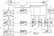
図1は、1つ又はそれ以上のガスタービンエンジン(GT)12、熱回収蒸気発生器(HRSG)14、1つ又はそれ以上の蒸気タービン(ST)16、蒸気凝縮機23、並びに電力会社網20及び電力網に接続された顧客などの電力需要に対して電力を出力する1つ又はそれ以上の発電機18を含む複合サイクル(CC)発電システム(プラント)10の概略図である。
FIG. 1 illustrates one or more gas turbine engines (GT) 12, a heat recovery steam generator (HRSG) 14, one or more steam turbines (ST) 16, a
制御システム22は、蒸気タービンのロータ温度、HRSG及び蒸気タービンへの蒸気入口及び出口圧力、ガス及び蒸気タービンの各々による電力出力、ガスタービンによる燃料流量及び消費量、並びに発電機の出力など、システムの構成要素の動作条件を検知することによりCC発電システムを監視し制御する。制御システムは、CC発電システムの下現在及び履歴上の動作条件に関するデータの取り込み、記憶、及び提供を行う。
The
制御システム22はまた、ガスタービンの各々への燃料流量の調整、ガスタービン及び蒸気タービンにおける起動シーケンスの開始、並びにシステムが給電可能負荷レベルに到達した後の電力供給網への発電機の電力出力の連結など、CC発電システムに対して指令を提供する。例えば、制御システムは、制御システムと対話するシステムオペレータにより入力又は承認された始動シーケンスに従ってCC発電システムを起動する指令を生成することができる。制御システム22は、中央処理ユニット(CPU)、ソフトウェア制御スーツなどのソフトウェアプログラムを格納するコンピュータメモリ、ユーザ表示スクリーン24、キーボードなどのユーザ入力デバイス26、並びにCC発電システムを監視するセンサからのセンサ信号及びシステムに関して生成されたデータを受け取る通信モジュールを有するコンピュータ制御システムとすることができる。
The
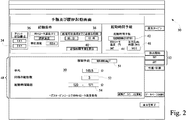
図2は、複合サイクル発電システムの提案された起動時間を算出するための例示的なヒューマン・マシン・インターフェース(HMI)を示すコンピュータ表示スクリーン24のスクリーン画像30である。スクリーン画像30は、プラントの始動シーケンスの推奨起動時間を算出するための情報及び選択可能な選択肢を提供する。スクリーン画像は、選択可能ナビゲーションボタン32を含み、オペレータが、入力デバイス26を用いて、起動期間算出スクリーン30と図3に示すような性能統計スクリーンとを切り替えるよう選択することができる。加えて、ナビゲーションボタン32を用いてプラント構成(1X1及び2X1で表記されたボタンバーを参照)を設定し、起動時間が予報されることになるプラントのプラント構成をコンピュータシステムに入力することができる。
FIG. 2 is a
スクリーン画像30は、システムに入力されて、プラントの始動シーケンスの起動時間を予報するのに使用される初期プラント条件を提示する。初期プラント条件は、プラント構成(手動で入力可能)、蒸気タービンの現在温度36(蒸気タービンのロータ温度を検出する温度センサに基づいて自動的に又は手動で入力することができる)、及びプラントが給電可能負荷レベルに到達するようスケジュールされている目標時間38を含む。
スクリーン画像上に表示されている入力条件34、36及び38が適正であることをオペレータが確認した後、オペレータが算出スクリーンボタン40を作動させることにより、コンピュータシステムは、予報アルゴリズムに入力条件を適用し、プラントの始動シーケンスを開始する予報起動時間を生成するようにする。起動時間予報42は、スクリーン画像30上に表示される。加えて、スクリーン画像は、始動シーケンスの起動時にプラント内の蒸気タービン(例えば、再熱(RH)蒸気タービン)の予期されるロータ温度44を表示し、始動シーケンスが開始された後に残り時間量46(例えば、145.5分)を表示することができる。
After the operator confirms that the
スクリーン画像30はまた、ナビゲーションボタン32により選択され且つロータ温度表示44に示される初期ロータ温度を有する同じ構成で作動している間、始動シーケンスを実行する同じプラント及び同様のプラントの履歴情報を表示することができる。履歴情報48は、蒸気ロータ温度の範囲51などの同様の条件及びプラント構成下でのプラントの始動シーケンスの平均期間の比較起動データ50を含むことができる。範囲51は、始動シーケンスの予報起動42時の推定ロータ温度44に対応するよう自動的に選択することができる。履歴情報はまた、同様の条件下で実施される始動シーケンスの計数の表示、及び同様の条件下で実施される始動シーケンスの時間長の範囲54を含むことができる。
The
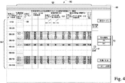
図3は、プラントの履歴始動プロセスに関する統計データを示すスクリーン画像60である。統計を見るために、オペレータは最初に、ボタン34を用いてプラント構成(例えば、1X1又は2X1)を入力し、起動蒸気タービンロータ温度(例えば、600〜700°F)に対応する温度範囲プルダウンメニュー62を選択する。選択された温度範囲は、スクリーン画像30における温度範囲51として用いることができる。或いは、温度範囲51、62は、プラントの始動シーケンスの起動時の蒸気タービンのロータの推定温度を含む範囲としてコンピュータによって自動的に選択することができる。このスクリーンは、起動時間の問題の解決、ベンチマーク、及び最適化を得ようとするプラントエンジニア及び管理者に合わせて調整される。
FIG. 3 is a
温度範囲62及びプラント構成34が選択されると、コンピュータシステムは、プラントによって実施される履歴始動シーケンスの統計チャート64を表示し、ここでは始動は、範囲62内の蒸気ロータ温度で開始される。チャート64は、種々の始動パラメータの始動データを示すように配列することができる。例えば、統計データは、時間(例えば、分)及び消費燃料(例えば、100万イギリス熱単位(MMBTU))の観点で始動データを示すことができる。
Once the
始動データはまた、「プレIPC」から「対負荷IPC」までのチャート64に分けることができる。期間プレIPCは、多くの場合、手動設定に従い、従って、プラントのオペレータにより行われる調整によって変化する。対負荷(給電可能負荷である)IPCからの期間は、自動化される傾向があり、オペレータの手動設定に従わない。チャート64で提示される統計データは、同じプラント構成(1X1又は2X1)及び起動時ロータ温度を有する幾つかの始動プロセスの平均値(EWMA)を表すことができる。提示される統計データは、平均値に加えて、履歴起動についての最小及び最大時間、並びに消費される燃料を含むことができる。加えて、提示される統計データは、本明細書で開示されるような自動予報機構でスケジュールされる(ステージ2)場合と、図9に示すような従来の手動による始動スケジューリング技法でスケジュールされる(ステージ1)、始動プロセスのデータを含むことができる。始動プロセスは、2つ又はそれ以上のステージを含むことができる。本明細書で開示される2つのステージは、図9における例証に過ぎない。
The start-up data can also be divided into a
スクリーン表示60はまた、始動シーケンスの起動時に蒸気タービンロータ温度に相関付けられた始動シーケンスの全期間のような、履歴プラント始動データの種々の構成を示すグラフ68を選択するグラフ選択ボタン66を含むことができる。始動シーケンスの起動時のロータ温度を相関付けるデータは、プレIPCに対する起動時間の期間及び給電可能負荷に対するIPCの期間に関してグラフ化することができる。説明部70は、スクリーン画像60上に提示されるグラフ69及び他のデータのテキスト説明を提供することができる。
The
プラントの始動シーケンスの起動は、先導するガスタービン(GT)が起動される時点として定義することができる。スクリーン画像60はまた、従来の手動による始動スケジューリング技法と比較して、本明細書で開示されるような自動予報機構を用いることによる時間及び燃料の節減の推定値を表示することができる。
Activation of the plant startup sequence can be defined as the time when the leading gas turbine (GT) is activated.
図4は、プラント及び可能な同様のプラントの始動プロセスのデータベース82(図1を参照)のデータベースフィールドを示すスクリーン画像80である。データベースは、始動シーケンスの起動時の蒸気タービンのロータ温度についての種々の温度範囲84のデータフィールドを有することができる。温度範囲84は、図2において参照符号51で示され、図3において参照符号62で示される温度範囲に対応することができる。データフィールドはまた、データベースに提示される各始動シーケンスの起動日;再熱及び高圧蒸気タービンなどのプラント内の蒸気タービンの1つ又はそれ以上についてのロータ温度;起動からIPC、IPCから給電可能負荷の時間期間(例えば、分)並びに始動プロセスの総時間;起動からIPC、IPCから給電可能負荷のエネルギー消費量(MMBTU)並びに始動プロセス中に消費された合計エネルギー;及び始動プロセス中のピークロータ応力に関するデータについての追加フィールド86を含むことができる。加えて、スクリーン表示80は、オペレータが特定の始動プロセスからのデータをデータベースに恒久的に入力可能にするデータ入力フィールド88を含むことができる。
FIG. 4 is a
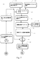
図5及び6は、複合サイクル(CC)発電システムを起動するのに必要な時間期間を予報するアルゴリズム100の例示的なフローチャートを示す。アルゴリズムの起動時には、データ102は、例えば、(i)CC発電システムの構成(例えば、ガスタービン及び蒸気タービンの1X1及び2X1構成)、(ii)蒸気タービンの現在メタル温度(例えば、再熱蒸気タービンのタービンバケットの第1の列のメタル温度)、及び(iii)CC発電システムが給電可能負荷レベルで電力を生成するようになるまでの時間量など、複合サイクル(CC)発電システム(プラント)の初期条件に関して収集される。
FIGS. 5 and 6 show an exemplary flowchart of an
蒸気タービンは、CC発電システムの他の構成要素と比べて加熱速度が遅いので、蒸気タービンのロータ温度は、入力条件として選択することができる。蒸気タービンは、CC発電システムが所期の負荷において給電可能電力を生成する温度まで加熱するのに最も長い時間を必要とする。ステップ102において入力されるこれらの初期条件は、アルゴリズム100を実行するコンピュータシステムのメモリ内に手動で入力することができ、ここでCC発電システムの起動期間についての予報を生成することになる。或いは、初期プラント条件は、CC発電システムを監視するセンサからのデータ収集に基づいて、CC発電システムからの給電可能負荷電力を発電負荷が必要とするときのタイミングスケジュールに関するなど、コンピュータに送られるデータについてコンピュータシステムにより自動的に取得することができる。
Since the steam turbine has a slower heating rate compared to other components of the CC power generation system, the rotor temperature of the steam turbine can be selected as an input condition. Steam turbines require the longest time for the CC power generation system to heat to a temperature that produces power available at the intended load. These initial conditions entered at
予報起動時間は、現在時間から、電力網に負荷を供給するようスケジュールされたときにシステムが給電可能負荷レベルに到達するように、蒸気タービンCC発電システムが起動される時点までの時間である。最初に、ステップ104において、予報起動期間(A)は、プラントが電力網に給電可能負荷を提供するようスケジュールされるまでの残りの期間(D)に等しいように設定される。起動期間(A)の初期設定は、プラントが給電可能負荷に直ちに到達するときの現実的な実起動時間ではない。
The forecast start-up time is the time from the current time until the time when the steam turbine CC power generation system is started so that the system reaches the loadable load level when it is scheduled to supply a load to the power grid. Initially, in
起動期間(A)の初期設定は、プラントが電力負荷レベルを供給するようスケジュールされたときに、プラントが給電可能電力負荷レベルに到達できるようになる実際の起動時間を決定する算出部109を開始するのに使用される。算出部109は、予報起動期間(A)が、時間期間(D)終了時にプラントの給電可能負荷電力レベルへの到達をもたらすことになるかどうかを判定する。残りの期間(D)は、プラントが給電可能負荷電力を提供するようスケジュールされるまでの残りの期間である。予報期間(A)が、時間期間(D)終了時にプラントの給電可能負荷電力レベルへの到達をもたらさない場合、予報時間が調整され、例えば、ステップ111において5分だけ減分される。
The initial setting of the start-up period (A) starts the
算出部109では、プラントが給電可能電力レベルに到達するまでの予報時間期間(A+Z)と、プラントが電力レベルに到達するようスケジュールされるまでの残りの期間(D)との間で比較106を行う。予報時間期間(A+Z)が、残りの期間(D)の所定時間期間106(例えば、5分)内にある場合、起動期間(A)は許容可能であり、アルゴリズム100は、現在時間に付加された起動期間として正確な起動時間を算出する。
The
ステップ110での算出109は、メタル冷却時間期間(M)と後続の始動持続期間との合計として期間(X)を求め、現在時間からプラントが給電可能負荷に到達するまでの期間を推定する。冷却時間期間(M)の間、蒸気タービンは冷却が継続され、蒸気タービンのロータのメタル温度は、現在ロータ温度まで下がる。時間「M」は、蒸気タービンが現在冷却温度まで冷却するのに要する時間数である。
The
始動シーケンスの期間(Z)を推定するために、アルゴリズムは、始動シーケンスが開始されたときに蒸気タービンの推定ロータ温度(Y)112を用いる。始動シーケンスが開始されたときのロータ温度(Y)を推定するために、アルゴリズム100は、現在ロータ温度から始動シーケンスの推定起動時間におけるロータ温度までのロータの冷却によるロータメタル温度低下を求める。
To estimate the duration (Z) of the startup sequence, the algorithm uses the estimated rotor temperature (Y) 112 of the steam turbine when the startup sequence is initiated. To estimate the rotor temperature (Y) when the start sequence is initiated, the
ステップ112において、冷却期間(X)を用いて、起動時間(A)での予測メタル温度(Y)を求める。メタル温度(Y)の決定は、例えば、再熱(RH)蒸気タービン内のタービンブレードの第1の列などの特定のメタル温度を相関付ける、コンピュータメモリ内に記憶されたルックアップテーブルを用いることができる。蒸気タービン/ロータのルックアップテーブル又はモデルは、RH蒸気タービンにおけるロータ冷却時間及び温度に関するプラントの履歴データに基づいて作成することができる。
In
ステップ114では、起動時間(A)として予測メタル温度(Y)に基づいて始動シーケンスの予報時間期間(Z)を求める。始動の時間期間(Z)は、起動時間(A)からCC発電システムが給電可能負荷電力レベルに到達するまでの期間である。予報始動時間期間(Z)は、予報始動時間期間(Z)を始動時間期間の開始である起動時間(A)のメタル温度(Y)に相関付ける、CC発電システムのコンピュータに格納されたルックアップテーブルから求めることができる。始動時間期間(Z)を決定するルックアップテーブルは、同じ構成(例えば、1X1及び2X1)を有する同じ又は同様のCC発電システムに対する前の始動点順からの経験的データに基づいて策定することができる。
In
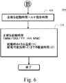
ステップ106において、起動時間(A)が決定され、CC発電システムが給電可能負荷を供給するようスケジュールされたときに時間(D)の所定範囲内にある始動時間期間(A)が得られる。現在時間及び起動までの時間(A)に基づいて、正確な起動時間が決定される。ステップ118において、図2に示すスクリーン画像に提示されることにより、正確な起動時間がシステムオペレータに表示される。加えて、表示は、起動時間、及びCC発電システムが給電可能負荷レベルに到達するまでの時間のメタル温度(Y)を示すことができる。アルゴリズム100により得られる技術的効果は、起動時間、予測メタル温度、及び給電可能負荷までの総時間の生成及び表示である。
In
予報起動時間(A)が、給電可能負荷の予定される時間(D)の所定期間(例えば、5分)内にない場合(ステップ106)、ステップ116において算出109が繰り返される。算出を繰り返す前に、ステップ111において、起動時間(A)は、5分の所定量などを減分される。起動時間(A)の算出の減分及び算出109の繰り返しによって、起動時間(A)は、給電可能負荷を電力網又は他の顧客施設に供給されるようスケジュールされる時間にCC発電システムが到達する結果をもたらす始動手順が得られるまで調整されることになる。
When the predicted activation time (A) is not within a predetermined period (for example, 5 minutes) of the scheduled time (D) of the power supplyable load (for example, 5 minutes) (step 106), the
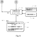
図7及び8は、CC発電システム(プラント)における予報起動時間(A)を決定するアルゴリズム120の例示的なフローチャートである。現在の蒸気ロータ温度124及び初期推定起動時間(A)126は、コンピュータへの入力データとして提供され、プラントのコンピュータのメモリ内に電気的に記憶される蒸気タービンロータモデル128に適用される。蒸気タービンロータモデル128は、再熱(RH)蒸気タービンなど、プラント内の蒸気タービンのロータのメタル冷却率をシミュレートする。モデル128は、蒸気タービン冷却期間中に種々の時間(例えば、5分毎)でのロータメタル温度を相関付けるルックアップテーブルとすることができる。現在ロータ温度及びプラントを起動する推定時間の入力データ124、126に基づいて、コンピュータは、蒸気タービンロータモデルにアクセスし、システムの起動時のロータの予測温度(Y)130を決定する。
7 and 8 are exemplary flowcharts of the
始動シーケンスの起動時の予測ロータ温度(Y)130及びプラント構成(1X1及び2X1)133は、同じプラント又は同様のプラントにおけるプラント起動の履歴起動のデータベース132にアクセスするのに用いる入力である。データベースは、プラント始動運転の起動からプラントが給電可能負荷に到達したときまでの時間期間に関する情報を有する。データベースは、最新の始動手順に関する情報を含むことができる。データベースを格納するコンピュータメモリに十分な記憶容量が不足している場合、古い始動期間に関するデータは、データベースから消去することができる。コンピュータは、データベース132にアクセスすることによって、始動シーケンスの予測始動時間期間(Z)134を生成し、ここで期間(Z)は、プラントの起動から該プラントが給電可能負荷に到達したときまでである。始動期間(Z)は、プラントが同じ構成を有して同様の蒸気タービンロータ温度で起動したときに実施されるプラントの前の始動シーケンスに基づく平均始動シーケンス挙動をベースとすることができる。
Predicted rotor temperature (Y) 130 and plant configuration (1X1 and 2X1) 133 at startup of the startup sequence are inputs used to access the database startup
ステップ136において、予測始動時間期間134が現在推定起動時間に付加され、予報起動時間と始動期間との総和を得る。プラントが給電可能負荷140に到達するよう予報されるまでの総時間は、プラントが給電可能負荷レベルに到達するようスケジュールされた目標時間(D)144と比較142される。
In
推定総時間(T)140と目標時間(D)144との差違が、許容差(α)の予め定義された期間内にある場合、現在推定起動時間(A)140がコンピュータによって関連表示デバイス148に出力され、該表示デバイスは、プラントが起動されて始動期間が始まる予報起動時間122を現在推定起動時間(A)138として月、日、及び年並びに時間及び分で示す。加えて、コンピュータは、始動シーケンスの起動時の蒸気タービンの予測ロータ温度(Y)、及び現在時間からプラントが給電可能電力負荷レベルに到達したときまでの推定総時間(T)を出力することができる。
If the difference between the estimated total time (T) 140 and the target time (D) 144 is within a predefined period of tolerance (α), the current estimated activation time (A) 140 is displayed by the computer in the associated
許容差(α)146の期間は、手動設定され且つプラントが給電可能電力負荷レベルに到達するのに許容可能な目標時間前後の時間期間(例えば、5分から30分)を定める入力とすることができる。 The period of tolerance (α) 146 may be an input that defines a time period (eg, 5 to 30 minutes) that is manually set and before and after a target time that is acceptable for the plant to reach a power loadable power load level. it can.
ステップ142において、目標時間期間(D)144と給電可能負荷(T)140までの現在推定総時間との間の差違が許容差期間146を超える場合には、プラント起動前の現在推定時間が減分(例えば、5分)され、プラント起動前の新しい現在推定時間(A)138を生成する。許容差(α)146の期間は、ステップ152において推定起動時間(A)を減分するのに使用されるのと同じ期間とすることができる。プラント起動前の新しい現在推定時間(A)138を用いて、アルゴリズム120が繰り返されて、プラントが給電可能負荷に到達するまでの新しい推定時間を生成する。プラントが給電可能負荷に到達するまでの総推定時間(T)が、プラントが給電可能負荷にある目標時間(D)の許容差期間内になるまで、現在推定起動時間(A)は順次減分され、アルゴリズムが繰り返されることになる。
In
図9は、複合サイクル発電システムの例示的な始動シーケンスを示すタイムチャートである。図示するように、シーケンスは、発電システムがシャットダウン160したときに始まり、この時点では、システム全体又は少なくともガスタービン(GT)の出力がゼロに低下する。シャットダウン後、高温ガスが蒸気タービン(ST)を通過しないので、STロータ温度は漸次的に低温になる。ロータは、ガスタービンからの高温ガスが蒸気タービンに適用されるときまで連続して冷却され、この時点164で蒸気タービンが回転すなわち「転動」を開始する。STロールポイントの前に、少なくとも先導するガスタービンが起動166される。STロールポイントの後、STロータ温度が、CC発電システムの出力168と共に上昇167し始める。STロータ温度が定常運転レベル170に到達すると、システムは、給電可能負荷レベル172に到達する。
FIG. 9 is a time chart illustrating an exemplary start sequence of the combined cycle power generation system. As shown, the sequence begins when the power generation system shuts down 160, at which point the power of the entire system or at least the gas turbine (GT) drops to zero. Since the hot gas does not pass through the steam turbine (ST) after the shutdown, the ST rotor temperature gradually decreases. The rotor is continuously cooled until hot gas from the gas turbine is applied to the steam turbine, at which point the steam turbine begins to rotate or “roll”. Prior to the ST roll point, at least the leading gas turbine is activated 166. After the ST roll point, the ST rotor temperature begins to rise 167 with the
オペレータは、CC発電システムが給電可能電力を供給するようスケジュールされたときに、システムに給電可能負荷レベルに到達させることを要求している。オペレータは、現在時間、現在時間でのSTロータ温度、並びにシステムが給電可能電力を供給するようスケジュールされるタイミングを認識する。この情報は、HMIツールに入力され、本明細書で開示されるアルゴリズムを適用し、少なくとも先導ガスタービンを起動するタイミング(期間A)を決定する。 The operator is requesting the system to reach a feedable load level when the CC power generation system is scheduled to supply feedable power. The operator recognizes the current time, the ST rotor temperature at the current time, and the timing when the system is scheduled to deliver power. This information is input into the HMI tool and applies the algorithm disclosed herein to determine at least when to start the lead gas turbine (period A).
本発明の特定の特徴のみを本明細書で例示し説明してきたが、当業者であれば、多くの変更形態及び変形が想起されるであろう。従って、添付の請求項は、本発明の真の技術的思想内にあるこのような全ての変更形態及び変形を保護することを意図している点を理解されたい。 While only certain features of the invention have been illustrated and described herein, many modifications and changes will occur to those skilled in the art. Accordingly, it is to be understood that the appended claims are intended to protect all such modifications and variations that fall within the true spirit of the invention.
10 複合サイクル(CC)発電システム
12 ガスタービン(複数)
14 熱回収蒸気発生器
16 蒸気タービン
18 発電機
20 電力会社網
22 制御システム
23 凝縮器
24 表示スクリーン
26 ユーザ入力デバイス
30 図2の算出の起動期間のスクリーン画像
32 ナビゲーションボタン
34 プラント構成
36 ロータ温度
38 プラントが給電可能負荷に到達する目標時間
40 算出ボタン
42 起動時間予報
44 起動時のロータ温度
46 起動までの時間
48 履歴データ
50 比較起動データ
51 ロータ温度範囲
52 同様の起動数
54 同様の始動シーケンスの期間範囲
60 図3のスクリーン表示
62 温度範囲選択
64 始動統計データ
66 入力ボタン
68 始動データのグラフ
70 グラフの説明部
72 推定燃料及び時間節減
80 図4のスクリーン画像
82 データベース(fig.1)
84 温度範囲
86 追加データベースフィールド
88 始動シーケンスのデータを記憶するためのデータ入力フィールド
100 予報起動期間に対するアルゴリズム
102 起動条件に関する初期情報
104 給電可能負荷時間に等しい起動時間
106 予報時間と給電可能出力時の時間との比較
108 正確な起動時間
109 算出(破線ボックス)
110 時間期間X
111 調整起動時間A
112 起動時間時のメタル温度(Y)決定
114 メタル温度(Y)の起動平均時間を決定する
116 算出109の繰り返し
118 起動時間,メタル温度、給電可能負荷までの時間を表示
120 図8及び7のアルゴリズム
122 予報起動時間
124 現在ロータ温度
126 初期推定起動時間(A)
128 蒸気タービンモデル
130 起動(Y)時の予測ロータ温度
132 履歴始動シーケンスのデータベース
133 プラント構成
134 予測始動期間
136 予報期間及び始動期間の合計
138 新しい推定起動時間
140 プラントが給電可能負荷に到達するまでの総時間
142 比較
144 プラントが給電可能負荷に到達する目標時間
146 起動時間の許容差期間
148 表示デバイス
150 予報起動時間
152 予報起動時間の減分
160 システムシャットダウン
162 STロータ温度低下
164 ST転動
166 GT起動
168 出力
170 定常STロータ温度
172 給電可能負荷レベル
10 Combined cycle (CC)
14 Heat
84
110 hour period X
111 Adjustment start-up time A
112 Determination of metal temperature (Y) at start-up
128
Claims (5)
(a)前記蒸気タービンの少なくとも1つのうちの最新時間に対応する温度を制御システムに入力する段階と、
(b)前記制御システムが、前記最新時間から前記発電システムが給電可能負荷にあるようにスケジュールされる目標時間までの期間として目標時間期間を決定する段階と、
(c)前記制御システムが、前記最新時間から前記発電システムの始動シーケンスの起動までの期間として予報起動時間期間を選択する段階と、
(d)前記予報起動時間期間及び前記蒸気タービンの少なくとも1つのうちの最新時間に対応する前記温度に基づいて、前記コントローラにより予報起動時間で生じる推定タービン温度を決定する段階と、
(e)前記推定タービン温度に基づいて、前記コントローラにより前記始動シーケンスの推定時間期間を決定する段階と、
(f)前記コントローラにより、前記予報起動時間期間と前記始動シーケンスの推定時間期間とを合計(136)し、前記最新時間から前記始動シーケンスの終わりまでの推定総時間期間を生成する段階と、
(g)前記コントローラにより、前記推定総時間期間及び前記目標時間期間を比較する段階と、
(h)前記コントローラが、前記比較の実施時に前記推定総時間が前記目標時間期間の所定期間内にあると判定した場合に、前記予報起動時間を出力する段階と、
(i)前記コントローラが、前記推定総時間が前記目標時間期間の所定期間外にあると判定した場合に、前記予報起動時間を減分する段階と、
前記段階(d)から(h)を繰り返す段階と、
を含む方法。 A combined cycle power generation system (GT) including a gas turbine engine (GT) (12), at least one steam turbine (ST) (16), and a controller (22) having a user input (26) and a display (24). 10) a method of predicting the startup time (42) of
(A) inputting a temperature corresponding to the latest time of at least one of the steam turbines into a control system;
(B) the control system determining a target time period as a period from the latest time to a target time scheduled so that the power generation system is in a load capable of being fed;
(C) the control system selecting a forecast activation time period as a period from the latest time to activation of the power generation system start sequence;
(D) determining an estimated turbine temperature occurring at a predicted startup time by the controller based on the temperature corresponding to a current startup time of the predicted startup time period and at least one of the steam turbines ;
(E) determining an estimated time period of the start sequence by the controller based on the estimated turbine temperature;
(F) summing (136) the forecast activation time period and the estimated time period of the start sequence by the controller to generate an estimated total time period from the latest time to the end of the start sequence;
(G) comparing, by the controller, the estimated total time period and the target time period;
(H) outputting the forecast activation time when the controller determines that the estimated total time is within a predetermined period of the target time period when the comparison is performed;
(I) decrementing the forecast activation time when the controller determines that the estimated total time is outside a predetermined period of the target time period;
Repeating steps (d) to (h);
Including methods.
The method of claim 1, wherein step (e) includes accessing (132) a startup sequence history database (82) having a steam turbine rotor temperature data field correlated in time during the startup sequence. Method.
Applications Claiming Priority (2)
| Application Number | Priority Date | Filing Date | Title |
|---|---|---|---|
| US12/565,945 | 2009-09-24 | ||
| US12/565,945 US8195339B2 (en) | 2009-09-24 | 2009-09-24 | System and method for scheduling startup of a combined cycle power generation system |
Publications (3)
| Publication Number | Publication Date |
|---|---|
| JP2011069356A JP2011069356A (en) | 2011-04-07 |
| JP2011069356A5 JP2011069356A5 (en) | 2012-07-19 |
| JP5145390B2 true JP5145390B2 (en) | 2013-02-13 |
Family
ID=43242171
Family Applications (1)
| Application Number | Title | Priority Date | Filing Date |
|---|---|---|---|
| JP2010198420A Active JP5145390B2 (en) | 2009-09-24 | 2010-09-06 | System and method for scheduling start-up of a combined cycle power generation system |
Country Status (4)
| Country | Link |
|---|---|
| US (1) | US8195339B2 (en) |
| EP (1) | EP2312407B1 (en) |
| JP (1) | JP5145390B2 (en) |
| CN (1) | CN102032045B (en) |
Families Citing this family (56)
| Publication number | Priority date | Publication date | Assignee | Title |
|---|---|---|---|---|
| US8321800B2 (en) | 2007-07-26 | 2012-11-27 | Areva T & D, Inc. | Methods for creating dynamic lists from selected areas of a power system of a utility company |
| US8833085B2 (en) * | 2010-01-27 | 2014-09-16 | General Electric Company | System and method for gas turbine startup control |
| US8364512B2 (en) * | 2010-02-01 | 2013-01-29 | Taiwan Semiconductor Manufacturing Company, Ltd. | Methods and systems for dynamic inventory control |
| US9093840B2 (en) * | 2010-07-02 | 2015-07-28 | Alstom Technology Ltd. | System tools for integrating individual load forecasts into a composite load forecast to present a comprehensive synchronized and harmonized load forecast |
| ITMI20102463A1 (en) * | 2010-12-30 | 2012-07-01 | Stamicarbon | METHOD FOR STARTING AND MANAGEMENT OF A COMBINED CYCLE THERMAL PLANT FOR ENERGY PRODUCTION AND ITS PLANT |
| JP5911128B2 (en) * | 2011-11-16 | 2016-04-27 | 三菱日立パワーシステムズ株式会社 | Power supply time calculation system for combined power plant |
| US10409234B2 (en) * | 2011-11-28 | 2019-09-10 | Kyocera Corporation | Power control apparatus, power control system, and power control method |
| US9372478B2 (en) * | 2012-01-04 | 2016-06-21 | General Electric Company | Control system for a power application |
| US9140192B2 (en) * | 2012-01-11 | 2015-09-22 | Alstom Technology Ltd. | Startup method for large steam turbines |
| CN102737351B (en) * | 2012-06-15 | 2015-06-10 | 广东电网公司电力科学研究院 | Multi-target and multi-constraint optimal scheduling method of fuel-steam combined cycle generator set |
| US9043263B2 (en) | 2012-07-24 | 2015-05-26 | General Electric Company | Systems and methods for control reliability operations using TMR |
| US9218233B2 (en) | 2012-07-24 | 2015-12-22 | Paul Venditti | Systems and methods for control reliability operations |
| US9665090B2 (en) | 2012-07-24 | 2017-05-30 | General Electric Company | Systems and methods for rule-based control system reliability |
| CN102880916B (en) * | 2012-09-07 | 2015-10-28 | 华南理工大学 | A kind of combustion gas, the scheduling of Steam Combined Cycle set optimization are improved one's methods |
| US20140123664A1 (en) * | 2012-11-05 | 2014-05-08 | General Electric Company | Systems and Methods for Generating a Predictable Load Upon Completion of a Start Sequence of a Turbine |
| US9201113B2 (en) | 2012-12-17 | 2015-12-01 | General Electric Company | Systems and methods for performing redundancy tests on turbine controls |
| EP2770171A1 (en) * | 2013-02-22 | 2014-08-27 | Alstom Technology Ltd | Method for providing a frequency response for a combined cycle power plant |
| JP6628250B2 (en) * | 2013-03-15 | 2020-01-08 | ユナイテッド テクノロジーズ コーポレイションUnited Technologies Corporation | Control system, method of controlling controlled device, and gas turbine engine |
| JP6037448B2 (en) * | 2013-03-15 | 2016-12-07 | 三菱日立パワーシステムズ株式会社 | Steam turbine power plant |
| US9696697B2 (en) * | 2013-09-04 | 2017-07-04 | General Electric Company | Automatic switching of HMI screens based on process, task, and abnormal deviation in a power plant |
| JP6295062B2 (en) * | 2013-11-07 | 2018-03-14 | 三菱日立パワーシステムズ株式会社 | Steam turbine plant start-up control device |
| JP6319998B2 (en) * | 2013-11-21 | 2018-05-09 | 三菱日立パワーシステムズ株式会社 | Steam turbine plant start-up control device |
| US9404395B2 (en) * | 2013-11-22 | 2016-08-02 | Siemens Aktiengesellschaft | Selective pressure kettle boiler for rotor air cooling applications |
| US9957843B2 (en) | 2013-12-31 | 2018-05-01 | General Electric Company | Methods and systems for enhancing control of power plant generating units |
| US20150184549A1 (en) | 2013-12-31 | 2015-07-02 | General Electric Company | Methods and systems for enhancing control of power plant generating units |
| US10138378B2 (en) | 2014-01-30 | 2018-11-27 | Monolith Materials, Inc. | Plasma gas throat assembly and method |
| US10370539B2 (en) | 2014-01-30 | 2019-08-06 | Monolith Materials, Inc. | System for high temperature chemical processing |
| US11939477B2 (en) | 2014-01-30 | 2024-03-26 | Monolith Materials, Inc. | High temperature heat integration method of making carbon black |
| BR112016017429B1 (en) | 2014-01-31 | 2022-10-04 | Monolith Materials, Inc | PLASMA TORCH |
| JP6290652B2 (en) * | 2014-02-27 | 2018-03-07 | 三菱重工業株式会社 | Power generation system and method for controlling power generation system |
| US10006315B2 (en) * | 2014-03-28 | 2018-06-26 | General Electric Company | System and method for improved control of a combined cycle power plant |
| US9912733B2 (en) | 2014-07-31 | 2018-03-06 | General Electric Company | System and method for maintaining the health of a control system |
| US11987712B2 (en) | 2015-02-03 | 2024-05-21 | Monolith Materials, Inc. | Carbon black generating system |
| EP3253904B1 (en) | 2015-02-03 | 2020-07-01 | Monolith Materials, Inc. | Regenerative cooling method and apparatus |
| JP6404743B2 (en) | 2015-02-24 | 2018-10-17 | 株式会社東芝 | Power generation plan support apparatus and power generation plan support method |
| US10287988B2 (en) * | 2015-03-27 | 2019-05-14 | General Electric Company | Methods and systems for enhancing operation of power plant generating units and systems |
| JP6235517B2 (en) * | 2015-03-27 | 2017-11-22 | ファナック株式会社 | Numerical control device with program presentation function according to the situation |
| JP6523788B2 (en) | 2015-05-22 | 2019-06-05 | 株式会社東芝 | Plant operating apparatus, plant operating method and plant operating program |
| JP6510923B2 (en) * | 2015-07-23 | 2019-05-08 | 三菱日立パワーシステムズ株式会社 | Start control apparatus and start control method for power plant |
| CA3032246C (en) | 2015-07-29 | 2023-12-12 | Monolith Materials, Inc. | Dc plasma torch electrical power design method and apparatus |
| WO2017027385A1 (en) | 2015-08-07 | 2017-02-16 | Monolith Materials, Inc. | Method of making carbon black |
| US20170066923A1 (en) | 2015-09-09 | 2017-03-09 | Monolith Materials, Inc. | Circular few layer graphene |
| CA3034212C (en) | 2015-09-14 | 2023-08-01 | Monolith Materials, Inc. | Carbon black from natural gas |
| ES2983689T3 (en) | 2016-04-29 | 2024-10-24 | Monolith Mat Inc | Torch Stinger Method and Apparatus |
| CN109562347A (en) | 2016-04-29 | 2019-04-02 | 巨石材料公司 | Grain processing technique and the addition of the second heat of equipment |
| US10436057B2 (en) * | 2016-12-23 | 2019-10-08 | Bechtel Infrastructure and Power Corporation | Gas turbine combined cycle for high flexibility |
| US10487750B2 (en) * | 2017-02-27 | 2019-11-26 | General Electric Company | System and method for predicting and enhancing power plant startup time |
| WO2018165483A1 (en) | 2017-03-08 | 2018-09-13 | Monolith Materials, Inc. | Systems and methods of making carbon particles with thermal transfer gas |
| CN115746586A (en) | 2017-04-20 | 2023-03-07 | 巨石材料公司 | Particle system and method |
| EP3425177B1 (en) * | 2017-07-05 | 2020-03-25 | Ansaldo Energia Switzerland AG | A method for starting up a combined cycle power plant |
| MX2020002215A (en) | 2017-08-28 | 2020-08-20 | Monolith Mat Inc | Systems and methods for particle generation. |
| WO2019046324A1 (en) | 2017-08-28 | 2019-03-07 | Monolith Materials, Inc. | PARTICULAR SYSTEMS AND METHODS |
| CA3116989C (en) | 2017-10-24 | 2024-04-02 | Monolith Materials, Inc. | Particle systems and methods |
| JP6833138B2 (en) * | 2018-12-12 | 2021-02-24 | 三菱電機株式会社 | Air conditioning control device and air conditioning control method |
| US11522478B2 (en) | 2021-05-05 | 2022-12-06 | Cummins Power Generation Inc. | Systems and methods for predictive load response |
| CN113449443B (en) * | 2021-09-01 | 2021-11-30 | 深圳百胜扬工业电子商务平台发展有限公司 | Data loading modeling scheduling method and device |
Family Cites Families (25)
| Publication number | Priority date | Publication date | Assignee | Title |
|---|---|---|---|---|
| US4222229A (en) * | 1978-10-18 | 1980-09-16 | Westinghouse Electric Corp. | Multiple turbine electric power plant having a coordinated control system with improved flexibility |
| US5042246A (en) * | 1989-11-06 | 1991-08-27 | General Electric Company | Control system for single shaft combined cycle gas and steam turbine unit |
| US5933345A (en) * | 1996-05-06 | 1999-08-03 | Pavilion Technologies, Inc. | Method and apparatus for dynamic and steady state modeling over a desired path between two end points |
| US6775597B1 (en) * | 1998-05-13 | 2004-08-10 | Siemens Power Transmission & Distribution | Security constrained optimal power flow method |
| JP3977922B2 (en) * | 1998-05-21 | 2007-09-19 | 三菱重工業株式会社 | Determination method of steam turbine start mode |
| JP4301692B2 (en) * | 2000-03-31 | 2009-07-22 | 三菱重工業株式会社 | gas turbine |
| US6370880B1 (en) * | 2000-11-09 | 2002-04-16 | General Electric Company | Fuel gas moisturization control system for start-up, high load operation and shutdown |
| US6795798B2 (en) * | 2001-03-01 | 2004-09-21 | Fisher-Rosemount Systems, Inc. | Remote analysis of process control plant data |
| DE60207048T2 (en) * | 2001-03-01 | 2006-07-13 | Fisher-Rosemount Systems, Inc., Austin | GENERATION AND DISPLAY OF DIRECTORY IN A PROCESSING SYSTEM |
| US7124097B2 (en) * | 2002-01-23 | 2006-10-17 | Xerox Corporation | Method and system for ordering a consumable for a device |
| JP3753113B2 (en) * | 2002-08-23 | 2006-03-08 | 三菱電機株式会社 | Generator control device |
| JP2004116416A (en) * | 2002-09-26 | 2004-04-15 | Toshiba Corp | Operating method of combined cycle power plant |
| US7054706B2 (en) * | 2003-06-30 | 2006-05-30 | Intel Corporation | Managing supply chains with model predictive control |
| US7197485B2 (en) * | 2003-07-16 | 2007-03-27 | United Technologies Corporation | Square root method for computationally efficient model predictive control |
| JP4115958B2 (en) * | 2004-03-26 | 2008-07-09 | 株式会社東芝 | Plant operation schedule optimization method and optimization system |
| JP2006180673A (en) * | 2004-12-24 | 2006-07-06 | Mitsubishi Electric Corp | Generator operation plan creation device |
| US7584024B2 (en) * | 2005-02-08 | 2009-09-01 | Pegasus Technologies, Inc. | Method and apparatus for optimizing operation of a power generating plant using artificial intelligence techniques |
| JP4723884B2 (en) * | 2005-03-16 | 2011-07-13 | 株式会社東芝 | Turbine start control device and start control method thereof |
| US20060282177A1 (en) * | 2005-06-10 | 2006-12-14 | United Technologies Corporation | System and method of applying interior point method for online model predictive control of gas turbine engines |
| US20070017207A1 (en) * | 2005-07-25 | 2007-01-25 | General Electric Company | Combined Cycle Power Plant |
| US20070055392A1 (en) * | 2005-09-06 | 2007-03-08 | D Amato Fernando J | Method and system for model predictive control of a power plant |
| US7571057B2 (en) * | 2005-09-16 | 2009-08-04 | General Electric Company | System and method for monitoring degradation |
| JP2007138856A (en) * | 2005-11-21 | 2007-06-07 | Chugoku Electric Power Co Inc:The | System and method for forecasting starting schedule of steam turbine plant, program for forecasting and record medium storing program |
| US7937928B2 (en) * | 2008-02-29 | 2011-05-10 | General Electric Company | Systems and methods for channeling steam into turbines |
| US8352148B2 (en) * | 2008-05-21 | 2013-01-08 | General Electric Company | System for controlling input profiles of combined cycle power generation system |
-
2009
- 2009-09-24 US US12/565,945 patent/US8195339B2/en active Active
-
2010
- 2010-09-06 JP JP2010198420A patent/JP5145390B2/en active Active
- 2010-09-17 EP EP10177493.3A patent/EP2312407B1/en active Active
- 2010-09-21 CN CN201010500669.9A patent/CN102032045B/en active Active
Also Published As
| Publication number | Publication date |
|---|---|
| CN102032045A (en) | 2011-04-27 |
| EP2312407A3 (en) | 2013-08-21 |
| EP2312407B1 (en) | 2016-12-28 |
| JP2011069356A (en) | 2011-04-07 |
| CN102032045B (en) | 2015-06-17 |
| US20110071692A1 (en) | 2011-03-24 |
| EP2312407A2 (en) | 2011-04-20 |
| US8195339B2 (en) | 2012-06-05 |
Similar Documents
| Publication | Publication Date | Title |
|---|---|---|
| JP5145390B2 (en) | System and method for scheduling start-up of a combined cycle power generation system | |
| US8352148B2 (en) | System for controlling input profiles of combined cycle power generation system | |
| US10527304B2 (en) | Demand response based air conditioning management systems and method | |
| CN101292076B (en) | Method and device for determining service life consumption of individual components of a fossil fuel-fired power station, especially a combined gas and steam turbine power plant | |
| JP6180826B2 (en) | Energy management server, energy management method and program | |
| US7801711B2 (en) | Generated steam estimation method and device for heat recovery steam generator, and maintenance planning support method and system for power generation facility | |
| JP2011048688A (en) | Plant life cycle evaluation device and method | |
| JP6404650B2 (en) | Device operation set value determination device, device operation set value determination method, and device operation set value determination program | |
| US20050027586A1 (en) | Methods and systems for generating a financial report | |
| JP6533952B2 (en) | Apparatus and method for predicting cooling water temperature of heat source equipment operating with cooling water, and program | |
| JP6582755B2 (en) | Method, system, and program for optimizing operation plan of heat source equipment network | |
| CN106950926B (en) | System and method for controlling and monitoring a power generation facility | |
| JP6812169B2 (en) | Planning equipment and planning method for operation of energy demand equipment | |
| EP3366893B1 (en) | System and method for predicting and enhancing power plant startup time | |
| US11636558B2 (en) | Energy management system and energy management method for water supply | |
| EP3121392B1 (en) | Start-up control device and start-up control method for power plant | |
| US20160247074A1 (en) | Power generation planning support apparatus and power generation planning support method | |
| CN103136630B (en) | Method and system for the operation that directs a factory | |
| JP2020003122A (en) | Hot water supply device management control device, and hot water supply device management control program | |
| JP2011169234A (en) | Operation schedule calculation device | |
| JP2005223964A (en) | Cogeneration system operation control system | |
| JP2007138856A (en) | System and method for forecasting starting schedule of steam turbine plant, program for forecasting and record medium storing program | |
| WO2012120555A1 (en) | Solar heat utilization gas turbine system | |
| JP2017028764A (en) | Demand power control apparatus and demand power control method | |
| JP6641854B2 (en) | Method, system, and program for creating device characteristics of a cogeneration system |
Legal Events
| Date | Code | Title | Description |
|---|---|---|---|
| A521 | Request for written amendment filed |
Free format text: JAPANESE INTERMEDIATE CODE: A523 Effective date: 20120528 |
|
| A621 | Written request for application examination |
Free format text: JAPANESE INTERMEDIATE CODE: A621 Effective date: 20120528 |
|
| A871 | Explanation of circumstances concerning accelerated examination |
Free format text: JAPANESE INTERMEDIATE CODE: A871 Effective date: 20120528 |
|
| A975 | Report on accelerated examination |
Free format text: JAPANESE INTERMEDIATE CODE: A971005 Effective date: 20120625 |
|
| A131 | Notification of reasons for refusal |
Free format text: JAPANESE INTERMEDIATE CODE: A131 Effective date: 20120710 |
|
| A521 | Request for written amendment filed |
Free format text: JAPANESE INTERMEDIATE CODE: A523 Effective date: 20121003 |
|
| TRDD | Decision of grant or rejection written | ||
| A01 | Written decision to grant a patent or to grant a registration (utility model) |
Free format text: JAPANESE INTERMEDIATE CODE: A01 Effective date: 20121030 |
|
| A01 | Written decision to grant a patent or to grant a registration (utility model) |
Free format text: JAPANESE INTERMEDIATE CODE: A01 |
|
| A61 | First payment of annual fees (during grant procedure) |
Free format text: JAPANESE INTERMEDIATE CODE: A61 Effective date: 20121126 |
|
| FPAY | Renewal fee payment (event date is renewal date of database) |
Free format text: PAYMENT UNTIL: 20151130 Year of fee payment: 3 |
|
| R150 | Certificate of patent or registration of utility model |
Ref document number: 5145390 Country of ref document: JP Free format text: JAPANESE INTERMEDIATE CODE: R150 |
|
| R250 | Receipt of annual fees |
Free format text: JAPANESE INTERMEDIATE CODE: R250 |
|
| R250 | Receipt of annual fees |
Free format text: JAPANESE INTERMEDIATE CODE: R250 |
|
| R250 | Receipt of annual fees |
Free format text: JAPANESE INTERMEDIATE CODE: R250 |
|
| R250 | Receipt of annual fees |
Free format text: JAPANESE INTERMEDIATE CODE: R250 |
|
| R250 | Receipt of annual fees |
Free format text: JAPANESE INTERMEDIATE CODE: R250 |
|
| R250 | Receipt of annual fees |
Free format text: JAPANESE INTERMEDIATE CODE: R250 |
|
| R250 | Receipt of annual fees |
Free format text: JAPANESE INTERMEDIATE CODE: R250 |
|
| R250 | Receipt of annual fees |
Free format text: JAPANESE INTERMEDIATE CODE: R250 |
|
| S111 | Request for change of ownership or part of ownership |
Free format text: JAPANESE INTERMEDIATE CODE: R313113 |
|
| R350 | Written notification of registration of transfer |
Free format text: JAPANESE INTERMEDIATE CODE: R350 |
|
| R250 | Receipt of annual fees |
Free format text: JAPANESE INTERMEDIATE CODE: R250 |