JP5145292B2 - Air-fuel ratio sensor and air-fuel ratio measurement method - Google Patents
Air-fuel ratio sensor and air-fuel ratio measurement method Download PDFInfo
- Publication number
- JP5145292B2 JP5145292B2 JP2009147248A JP2009147248A JP5145292B2 JP 5145292 B2 JP5145292 B2 JP 5145292B2 JP 2009147248 A JP2009147248 A JP 2009147248A JP 2009147248 A JP2009147248 A JP 2009147248A JP 5145292 B2 JP5145292 B2 JP 5145292B2
- Authority
- JP
- Japan
- Prior art keywords
- potential difference
- fuel ratio
- air
- voltage
- electrode
- Prior art date
- Legal status (The legal status is an assumption and is not a legal conclusion. Google has not performed a legal analysis and makes no representation as to the accuracy of the status listed.)
- Expired - Fee Related
Links
- 239000000446 fuel Substances 0.000 title claims description 69
- 238000000691 measurement method Methods 0.000 title description 4
- 239000007789 gas Substances 0.000 claims description 55
- 238000005086 pumping Methods 0.000 claims description 44
- 230000001590 oxidative effect Effects 0.000 claims description 37
- 239000007784 solid electrolyte Substances 0.000 claims description 33
- MYMOFIZGZYHOMD-UHFFFAOYSA-N Dioxygen Chemical compound O=O MYMOFIZGZYHOMD-UHFFFAOYSA-N 0.000 claims description 25
- 229910001882 dioxygen Inorganic materials 0.000 claims description 25
- 238000009792 diffusion process Methods 0.000 claims description 12
- 238000000034 method Methods 0.000 claims description 9
- 238000001514 detection method Methods 0.000 claims description 4
- 239000001301 oxygen Substances 0.000 description 42
- 229910052760 oxygen Inorganic materials 0.000 description 42
- QVGXLLKOCUKJST-UHFFFAOYSA-N atomic oxygen Chemical compound [O] QVGXLLKOCUKJST-UHFFFAOYSA-N 0.000 description 38
- 229910052739 hydrogen Inorganic materials 0.000 description 10
- UFHFLCQGNIYNRP-UHFFFAOYSA-N Hydrogen Chemical compound [H][H] UFHFLCQGNIYNRP-UHFFFAOYSA-N 0.000 description 9
- 239000001257 hydrogen Substances 0.000 description 9
- 238000005259 measurement Methods 0.000 description 9
- BASFCYQUMIYNBI-UHFFFAOYSA-N platinum Chemical compound [Pt] BASFCYQUMIYNBI-UHFFFAOYSA-N 0.000 description 8
- -1 oxygen ions Chemical class 0.000 description 4
- 229910052697 platinum Inorganic materials 0.000 description 4
- 238000010586 diagram Methods 0.000 description 3
- CURLTUGMZLYLDI-UHFFFAOYSA-N Carbon dioxide Chemical compound O=C=O CURLTUGMZLYLDI-UHFFFAOYSA-N 0.000 description 2
- 229910002076 stabilized zirconia Inorganic materials 0.000 description 2
- 229910002092 carbon dioxide Inorganic materials 0.000 description 1
- 239000001569 carbon dioxide Substances 0.000 description 1
- 239000000919 ceramic Substances 0.000 description 1
- 230000003647 oxidation Effects 0.000 description 1
- 238000007254 oxidation reaction Methods 0.000 description 1
- 230000002093 peripheral effect Effects 0.000 description 1
- 229920006395 saturated elastomer Polymers 0.000 description 1
- 239000000758 substrate Substances 0.000 description 1
- XLYOFNOQVPJJNP-UHFFFAOYSA-N water Chemical compound O XLYOFNOQVPJJNP-UHFFFAOYSA-N 0.000 description 1
Images
Landscapes
- Combined Controls Of Internal Combustion Engines (AREA)
Description
本発明は、空燃比センサ、及び空燃比測定方法に関する。 The present invention relates to an air-fuel ratio sensor and an air-fuel ratio measurement method.
従来、限界電流に基づいて雰囲気中の酸素濃度を測定する限界電流式酸素センサが知られている。この限界電流式酸素センサは、車両の排気ガスが排出される排気通路に配置され、空燃比を検出するための空燃比センサとして用いられることがある(例えば特許文献1参照)。 Conventionally, a limit current type oxygen sensor that measures the oxygen concentration in the atmosphere based on the limit current is known. This limiting current type oxygen sensor is disposed in an exhaust passage through which exhaust gas from a vehicle is discharged, and is sometimes used as an air-fuel ratio sensor for detecting an air-fuel ratio (see, for example, Patent Document 1).
しかし、従来の空燃比センサでは、理想空燃比が15%以上、すなわち余剰酸素が存在する酸化雰囲気において出力電流がリニアに変化するため空燃比の計測が可能であるものの、余剰酸素が存在しない還元雰囲気では出力電流がリニアに変化せず、空燃比の計測が困難となってしまう。 However, in the conventional air-fuel ratio sensor, the ideal air-fuel ratio is 15% or more, that is, the output current changes linearly in an oxidizing atmosphere in which surplus oxygen exists. In an atmosphere, the output current does not change linearly, making it difficult to measure the air-fuel ratio.
本発明はこのような従来の課題を解決するためになされたものであり、その目的とするところは、還元雰囲気における測定制度について向上させることが可能な空燃比センサ、及び空燃比測定方法を提供することにある。 The present invention has been made to solve such conventional problems, and an object of the present invention is to provide an air-fuel ratio sensor and an air-fuel ratio measurement method capable of improving the measurement system in a reducing atmosphere. There is to do.
本発明の空燃比センサは、定電流回路から供給される定電流に応じた濃度の酸素ガスをガス律速体に供給するポンピングセルと、電圧回路から電圧が印加されると共に、前記ポンピングセルによって供給された酸素ガスの濃度と自然拡散により前記ガス律速体に導入されたガスの濃度とに応じた電流を出力可能なセンサセルと、前記センサセルの電極間の電位差を検出する電位差検出手段と、前記電位差検出手段により検出された電位差に応じて、前記電圧回路の電圧値を制御する制御手段と、を備えることを特徴とする。 The air-fuel ratio sensor of the present invention includes a pumping cell that supplies oxygen gas having a concentration corresponding to a constant current supplied from a constant current circuit to a gas rate limiting body, a voltage applied from the voltage circuit, and a supply from the pumping cell. A sensor cell capable of outputting a current according to the concentration of the oxygen gas and the concentration of the gas introduced into the gas rate limiting body by natural diffusion; a potential difference detecting means for detecting a potential difference between the electrodes of the sensor cell; and the potential difference Control means for controlling the voltage value of the voltage circuit according to the potential difference detected by the detection means.
また、本発明の空燃比センサにおいて、前記制御手段は、前記電位差が所定値以上である場合に還元雰囲気であると判断して前記電圧回路の電圧値を還元雰囲気に応じた電圧値とすると共に、前記電位差が所定値未満である場合に酸化雰囲気であると判断して前記電圧回路の電圧値を酸化雰囲気に応じた電圧値とすることが好ましい。 In the air-fuel ratio sensor of the present invention, the control means determines that the atmosphere is a reducing atmosphere when the potential difference is greater than or equal to a predetermined value, and sets the voltage value of the voltage circuit to a voltage value corresponding to the reducing atmosphere. Preferably, when the potential difference is less than a predetermined value, it is determined that the atmosphere is an oxidizing atmosphere, and the voltage value of the voltage circuit is set to a voltage value corresponding to the oxidizing atmosphere.
この空燃比センサによれば、センサセルの電極間の電位差を検出し、検出された電位差に応じて、電圧回路の電圧値を制御する。ここで、本件出願人は、酸化雰囲気におけるセンサセルの電極間電位差と、還元雰囲気におけるセンサセルの電極間電位差が異なることを見出した。すなわち、還元雰囲気において一方の電極の酸素濃度はポンピングセル側から供給される酸素により酸素濃度が高くなるが、他方の電極の酸素濃度は還元雰囲気に曝されて酸素濃度が低くなる。このように、電極間において酸素濃度に差が生じる。これにより、電極間電位差が異なることとなり、酸化雰囲気であるか還元雰囲気であるかを判断でき、これに応じて電圧回路の印加電圧を設定できることとなる。従って、酸化雰囲気においても還元雰囲気においても出力電流がリニアに変化するように電圧回路の印加電圧を設定でき、還元雰囲気における測定制度について向上させることができる。 According to this air-fuel ratio sensor, the potential difference between the electrodes of the sensor cell is detected, and the voltage value of the voltage circuit is controlled according to the detected potential difference. Here, the present applicant has found that the potential difference between the electrodes of the sensor cell in the oxidizing atmosphere is different from the potential difference between the electrodes of the sensor cell in the reducing atmosphere. That is, in the reducing atmosphere, the oxygen concentration of one electrode is increased by the oxygen supplied from the pumping cell side, but the oxygen concentration of the other electrode is exposed to the reducing atmosphere and the oxygen concentration is lowered. Thus, there is a difference in oxygen concentration between the electrodes. As a result, the potential difference between the electrodes is different, and it can be determined whether the atmosphere is an oxidizing atmosphere or a reducing atmosphere, and the applied voltage of the voltage circuit can be set accordingly. Therefore, the voltage applied to the voltage circuit can be set so that the output current changes linearly in both the oxidizing atmosphere and the reducing atmosphere, and the measurement system in the reducing atmosphere can be improved.
また、本発明の空燃比センサにおいて、前記電位差検出手段は、前記電圧回路からの印加電圧の遮断時において前記センサセルの電極間の電位差を検出することが好ましい。 In the air-fuel ratio sensor of the present invention, it is preferable that the potential difference detecting means detects a potential difference between the electrodes of the sensor cell when an applied voltage from the voltage circuit is cut off.
この空燃比センサによれば、電位差検出手段は、電圧回路からの印加電圧の遮断時においてセンサセルの電極間の電位差を検出する。このため、電位差検出にあたり印加電圧が電位差に合算してしまい、正確な電位差を検出できなくなってしまう事態を防止することができる。 According to this air-fuel ratio sensor, the potential difference detecting means detects the potential difference between the electrodes of the sensor cell when the applied voltage from the voltage circuit is cut off. For this reason, it is possible to prevent a situation in which the applied voltage is added to the potential difference in detecting the potential difference and an accurate potential difference cannot be detected.
また、本発明の空燃比センサにおいて、前記ポンピングセルは、前記ガス律速体側から順に第1電極と、ポンピングセル側固体電解質と、第2電極とを順次積層させた積層構造からなることが好ましい。 In the air-fuel ratio sensor of the present invention, it is preferable that the pumping cell has a laminated structure in which a first electrode, a pumping cell-side solid electrolyte, and a second electrode are sequentially laminated in order from the gas rate controlling body side.
この空燃比センサによれば、ポンピングセルは、ガス律速体側から順に第1電極と、ポンピングセル側固体電解質と、第2電極とを順次積層させた積層構造からなるため、簡素の構成により空燃比センサを製造等することができる。 According to this air-fuel ratio sensor, the pumping cell has a laminated structure in which the first electrode, the pumping cell-side solid electrolyte, and the second electrode are sequentially laminated in order from the gas rate controlling body side. A sensor can be manufactured.
また、本発明の空燃比センサにおいて、前記センサセルは、前記ガス律速体側から順に第3電極と、センサセル側固体電解質と、第4電極とを順次積層させた積層構造からなることが好ましい。 In the air-fuel ratio sensor of the present invention, it is preferable that the sensor cell has a laminated structure in which a third electrode, a sensor cell-side solid electrolyte, and a fourth electrode are sequentially laminated in order from the gas rate-limiting body side.
この空燃比センサによれば、センサセルは、ガス律速体側から順に第3電極と、センサセル側固体電解質と、第4電極とを順次積層させた積層構造からなるため、簡素の構成により空燃比センサを製造等することができる。 According to this air-fuel ratio sensor, the sensor cell has a laminated structure in which the third electrode, the sensor cell-side solid electrolyte, and the fourth electrode are sequentially laminated in order from the gas rate-limiting body side. It can be manufactured.
また、本発明の空燃比測定方法は、定電流回路から供給される定電流に応じた濃度の酸素ガスをガス律速体に供給するポンピングセルと、電圧回路から電圧が印加されると共に、前記ポンピングセルによって供給された酸素ガスの濃度と前記ガス律速体の自然拡散によりガス律速体に導入されたガスの濃度とに応じた電流を出力可能なセンサセルと、を備えた空燃比センサの空燃比測定方法であって、前記センサセルの電極間の電位差を検出する電位差検出工程と、前記電位差検出工程において検出された電位差に応じて、前記電圧回路の電圧値を制御する制御工程と、を有することを特徴とする。 Further, the air-fuel ratio measuring method of the present invention includes a pumping cell that supplies oxygen gas having a concentration corresponding to a constant current supplied from a constant current circuit to a gas rate limiting body, a voltage is applied from a voltage circuit, and the pumping An air-fuel ratio measurement of an air-fuel ratio sensor comprising: a sensor cell capable of outputting a current according to the concentration of oxygen gas supplied by the cell and the concentration of gas introduced into the gas rate-limiting body by natural diffusion of the gas rate-limiting body A potential difference detecting step for detecting a potential difference between the electrodes of the sensor cell; and a control step for controlling a voltage value of the voltage circuit according to the potential difference detected in the potential difference detecting step. Features.
この空燃比測定方法によれば、センサセルの電極間の電位差を検出し、検出された電位差に応じて、電圧回路の電圧値を制御する。ここで、本件出願人は、酸化雰囲気におけるセンサセルの電極間電位差と、還元雰囲気におけるセンサセルの電極間電位差が異なることを見出した。すなわち、還元雰囲気において一方の電極の酸素濃度はポンピングセル側から供給される酸素により酸素濃度が高くなるが、他方の電極の酸素濃度は還元雰囲気に曝されて酸素濃度が低くなる。このように、電極間において酸素濃度に差が生じる。これにより、電極間電位差が異なることとなり、酸化雰囲気であるか還元雰囲気であるかを判断でき、これに応じて電圧回路の印加電圧を設定できることとなる。従って、酸化雰囲気においても還元雰囲気においても出力電流がリニアに変化するように電圧回路の印加電圧を設定でき、還元雰囲気における測定制度について向上させることができる。 According to this air-fuel ratio measuring method, the potential difference between the electrodes of the sensor cell is detected, and the voltage value of the voltage circuit is controlled according to the detected potential difference. Here, the present applicant has found that the potential difference between the electrodes of the sensor cell in the oxidizing atmosphere is different from the potential difference between the electrodes of the sensor cell in the reducing atmosphere. That is, in the reducing atmosphere, the oxygen concentration of one electrode is increased by the oxygen supplied from the pumping cell side, but the oxygen concentration of the other electrode is exposed to the reducing atmosphere and the oxygen concentration is lowered. Thus, there is a difference in oxygen concentration between the electrodes. As a result, the potential difference between the electrodes is different, and it can be determined whether the atmosphere is an oxidizing atmosphere or a reducing atmosphere, and the applied voltage of the voltage circuit can be set accordingly. Therefore, the voltage applied to the voltage circuit can be set so that the output current changes linearly in both the oxidizing atmosphere and the reducing atmosphere, and the measurement system in the reducing atmosphere can be improved.
本発明によれば、還元雰囲気における測定制度について向上させることができる。 According to the present invention, it is possible to improve the measurement system in a reducing atmosphere.
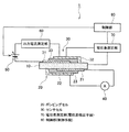
以下、本発明の好適な実施形態を図面に基づいて説明する。図1は、本発明の実施形態に係る空燃比センサの構成図である。図1に示す空燃比センサ1は、車両の排気ガスが排出される排気通路に配置され、空燃比を検出するためのものである。
DESCRIPTION OF EXEMPLARY EMBODIMENTS Hereinafter, preferred embodiments of the invention will be described with reference to the drawings. FIG. 1 is a configuration diagram of an air-fuel ratio sensor according to an embodiment of the present invention. An air-
この空燃比センサ1は、ガス律速体10と、ポンピングセル20と、センサセル30と、定電流回路40と、電圧回路50と、出力電流測定部60と、電位差測定部(電位差検出手段)70と、制御部(制御手段)80とを備えている。
The air-
ガス律速体10は、例えば多孔質セラミック基板からなり、拡散律速された酸素ガスをセンサセル30側に供給するものとして機能する。
The gas
ポンピングセル20は、酸素ガスをガス律速体10に供給するものであって、ガス律速体10側から順に、第1電極21と、固体電解質(ポンピングセル側固体電解質)23と、第2電極22とを積層した積層構造となっている。詳細に第1電極21は、白金などからなる例えば平板状の部材であって、ガス律速体10の一面側に設けられている。固体電解質23は、安定化ジルコニアからなる部材であって、図1に示すように例えば断面略L字状に形成されている。この固体電解質23は、第1電極21の一部を覆うと共にL字の先端側がガス律速体10に接するように配置されている。第2電極22は、第1電極21と同様に白金などからなり、例えば断面略L字状に形成されている。この第2電極22は、固体電解質23の一部を覆うと共にL字の先端側がガス律速体10に接するように配置されている。
The
なお、各電極21,22及び固体電解質23は、図1に示した形状に限るものではない。例えば、第2電極22及び固体電解質23がすべて平板状であってもよいし、第1電極21が断面L字状であってもよい。また、各電極21,22及び固体電解質23は、他の形状であってもよい。加えて、各電極21,22及び固体電解質23を平面視した形状は、各電極21,22の配索の関係などから種々の形状を採用可能である。
In addition, each
センサセル30は、ガス濃度に応じた電流を発生させるものであって、ガス律速体10側から順に、第3電極31と、固体電解質(センサセル側固体電解質)33と、第4電極32とを積層した積層構造となっている。詳細に第3電極31は、白金などからなる例えば平板状の部材であって、ガス律速体10の他面側に設けられている。固体電解質33は、安定化ジルコニアからなる部材であって、図1に示すように例えば断面略L字状に形成されている。この固体電解質33は、第3電極31の一部を覆うと共にL字の先端側がガス律速体10に接するように配置されている。第4電極32は、第3電極31と同様に白金などからなり、例えば断面略L字状に形成されている。この第4電極32は、固体電解質33の一部を覆うと共にL字の先端側がガス律速体10に接するように配置されている。
The
なお、各電極21,22及び固体電解質23は、図1に示した形状に限るものではない。例えば、第2電極22及び固体電解質23がすべて平板状であってもよいし、第1電極21が断面L字状であってもよい。また、各電極21,22及び固体電解質23は、他の形状であってもよい。加えて、各電極21,22及び固体電解質23を平面視した形状は、各電極21,22の配索の関係などから種々の形状を採用可能である。
In addition, each
定電流回路40は、ポンピングセル20に定電流を供給するものである。この定電流回路40は、第1電極21が陰極で第2電極22が陽極となるように接続される。また、定電流回路40の接続により、ポンピングセル20は、定電流に応じた濃度の酸素ガスをガス律速体10に供給することとなる。
The constant
電圧回路50は、センサセル30に電圧を印加するものである。また、センサセル30と電圧回路50との間には、出力電流測定部60が直列接続されている。出力電流測定部60は、センサセル30の電極31,32間に流れる電流の値を測定するものである。
The
電位差測定部70は、センサセル30の電極31,32間の電位差を検出するものである。制御部80は、空燃比センサ1の周囲雰囲気が酸化雰囲気(余剰酸素が存在する雰囲気)であるか還元雰囲気(酸素がゼロ又はほぼゼロの雰囲気)であるかに応じて、電圧回路50の電圧値を制御するものである。周囲雰囲気が酸化雰囲気であるか還元雰囲気であるかについては、電位差測定部70により検出された電位差に応じて判断される。
The potential
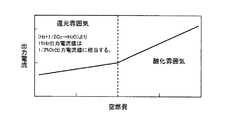
次に、本実施形態に係る空燃比センサ1の基本動作を説明する。まず、定電流回路40はポンピングセル20に定電流を供給する。これにより、ポンピングセル20は、第2電極22において酸素ガスO2、水蒸気H2O、及び炭酸ガスCO2を下記式により分解する。
O2+4e−→2O2−
2H2O+2e−→2H2+O2−
CO2+4e−→C+2O2−
また、分解された酸素イオンは固体電解質23へ汲み取られ、固体電解質23中を伝導し、第1電極21に達する。そして、酸素イオンは、第1電極21において電子を放出し、酸素ガスとなってガス律速体10に導入される。
Next, the basic operation of the air-
O 2 + 4e − → 2O 2−
2H 2 O + 2e − → 2H 2 + O 2−
CO 2 + 4e − → C + 2O 2−
The decomposed oxygen ions are taken up by the
また、図1に示すように、ガス律速体10の側面などは電極21,31等が載置されておらず排気通路を流れる排ガスに曝されるため、ガス律速体10には自然拡散により排ガスが導入される。ここで、空燃比センサ1の周囲雰囲気が酸化雰囲気である場合、排ガス中の酸素が自然拡散によりガス律速体10に導入される。
Further, as shown in FIG. 1, since the
このため、センサセル30の第3電極31には、ポンピングセル20から送られてきた酸素ガスと自然拡散により導入された酸素ガスとが到達することとなる。そして、酸素ガスは第3電極31において電子を受け取って酸素イオンとなり、酸素イオンは、固体電解質33中を伝導し、第4電極32において電子を放出して酸素ガスとなる。特に、センサセル30では電極31,32において電子の授受があるため、電流が流れることとなる。また、流れる電流の値は、電圧回路50の電圧値が高くなると初期的には電圧値の上昇にあわせて高くなっていくが、ある電圧値以上となると電流値は上昇せずに飽和状態となる。これを限界電流という。
For this reason, the oxygen gas sent from the pumping
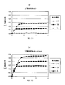
図2は、酸化雰囲気における限界電流を示すグラフであり、(a)はポンピングセル20に定電流を供給しない場合の限界電流を示し、(b)はポンピングセル20に定電流を供給した場合の限界電流を示している。
FIG. 2 is a graph showing the limit current in an oxidizing atmosphere, where (a) shows the limit current when a constant current is not supplied to the pumping
ポンピングセル20に定電流を供給しない場合、自然拡散のみによってガス律速体10に酸素ガスが導入されることとなる。この場合、図2(a)に示すように、酸素濃度が21%のときの限界電流は約0.28mAとなる。また、酸素濃度が10%であるとき、限界電流は約0.13mAとなり、酸素濃度が1%であるとき、限界電流は約0.01mAとなる。
When no constant current is supplied to the pumping
一方、ポンピングセル20に0.5mAの定電流を供給した場合、ポンピングセル20及び自然拡散の双方によって酸素ガスが導入されることとなる。この場合、図2(b)に示すように、酸素濃度が21%のときの限界電流は約0.55mAとなる。また、酸素濃度が10%である場合、限界電流は約0.42mAとなり、酸素濃度が1%である場合、限界電流は約0.27mAとなる。
On the other hand, when a constant current of 0.5 mA is supplied to the pumping
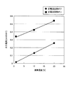
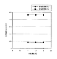
図3は、酸化雰囲気において電圧回路50による印加電圧が0.8Vのときの限界電流を示すグラフである。図3に示すように、酸化雰囲気において限界電流の値は酸素濃度にあわせてリニアに変化している。すなわち、限界電流の値は酸素濃度が高まるに従って、高くなる傾向にある。これにより、空燃比センサ1は、周囲雰囲気の酸素濃度を求めることができる。そして、酸素濃度から空燃比についても求めることが可能となる。
FIG. 3 is a graph showing the limit current when the voltage applied by the
ところで、図1に示す空燃比センサ1の周囲雰囲気が還元雰囲気である場合、ガス律速体10には、自然拡散により排ガス中の未燃ガス(HC、CO、H2)が導入される。
Meanwhile, when the ambient atmosphere of the air-
このため、ガス律速体10においてポンピングセル20から供給された酸素ガスは、未燃ガスと反応して消費されてしまう。このため、還元雰囲気では、図2及び図3に示した特性とは異なった特性が得られてしまう。
For this reason, the oxygen gas supplied from the pumping
図4は、還元雰囲気における電流を示すグラフであり、(a)はポンピングセル20に定電流を供給しない場合の電流を示し、(b)はポンピングセル20に定電流を供給した場合の電流を示している。
FIG. 4 is a graph showing the current in a reducing atmosphere, where (a) shows the current when a constant current is not supplied to the pumping
ポンピングセル20に定電流を供給しない場合、すなわちガス律速体10に酸素ガスが供給されず、自然拡散によって未燃ガスが導入されることとなる。この場合、図4(a)に示すように、限界電流が得られなくなってしまう。具体的に説明すると、水素濃度1%〜2%のいずれの場合においても、電流値が飽和する限界電流が存在しない。そして、電流値は、電圧回路50の印加電圧が約1Vあたりで急激に上昇してしまう。
When no constant current is supplied to the pumping
また、ポンピングセル20に0.5mAの定電流を供給した場合であっても、図4(b)に示すように限界電流が得られなくなってしまう。具体的には水素濃度が1%〜2%のいずれの場合においても、電流値は電圧回路50の印加電圧の上昇にあわせて緩やかに上昇してしまい、限界電流が得られなくなってしまう。
Further, even when a constant current of 0.5 mA is supplied to the pumping
図5は、還元雰囲気において電圧回路50による印加電圧が0.4Vのときの電流を示すグラフである。図5に示すように、還元雰囲気において電流の値は水素濃度にあわせてリニアに変化しない。このため、空燃比センサ1は、周囲雰囲気の水素濃度を求めることができず、空燃比についても求めることができない。
FIG. 5 is a graph showing the current when the voltage applied by the
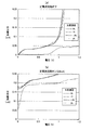
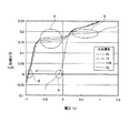
しかし、本件出願人は、還元雰囲気においても限界電流と同様の特性を示す領域が存在することを見出した。図6は、酸化雰囲気及び還元雰囲気における電流値を示すグラフである。なお、図6に示す数値等は空燃費センサ1の素子温度が650℃のときに得られたものを示している。
However, the present applicant has found that there is a region that exhibits the same characteristics as the limiting current even in a reducing atmosphere. FIG. 6 is a graph showing current values in an oxidizing atmosphere and a reducing atmosphere. Note that the numerical values and the like shown in FIG. 6 indicate those obtained when the element temperature of the air-
図6に示すように、水素濃度が1%〜2%の場合、符号aで示す箇所、すなわち電圧回路50の印加電圧が−0.7V〜0Vの箇所では、水素濃度に応じて電流値が異なっている。従って、還元雰囲気においては、電圧回路50の印加電圧を−0.7V〜0Vとすることにより、水素濃度に応じた電流値を得ることができ、水素濃度を測定できることとなる。
As shown in FIG. 6, when the hydrogen concentration is 1% to 2%, the current value varies depending on the hydrogen concentration at the location indicated by the symbol a, that is, at the location where the applied voltage of the
これに対して酸化雰囲気では、符号bで示す箇所、すなわち電圧回路50の印加電圧が0.3V〜1.0Vの箇所において、酸素濃度に応じて電流値が異なることとなる。このため、本実施形態に係る空燃比センサ1では、酸化雰囲気である場合には電圧回路50の印加電圧を例えば0.4V〜0.8V程度とし、還元雰囲気である場合には電圧回路50の印加電圧を例えば−0.7V〜−0.3V程度とする。これにより、出力電流測定部60は、酸化雰囲気と還元雰囲気との双方において、ガス濃度に応じた電流を得ることができる。
On the other hand, in the oxidizing atmosphere, the current value varies depending on the oxygen concentration at the location indicated by symbol b, that is, at the location where the applied voltage of the
また、本件出願人は、図6の符号c,dに示すように、酸化雰囲気と還元雰囲気とでは第3電極31と第4電極32との電位差に相違があることを見出した。すなわち、符号cに示すように、酸化雰囲気では電極31,32間の電位差が約0.2V程度であるが、還元雰囲気では電位差が約0.9Vまで上昇することを見出した。
Further, the present applicant has found that there is a difference in the potential difference between the
本実施形態に係る空燃比センサ1は、この電位差に基づいて、周囲雰囲気が酸化雰囲気であるか還元雰囲気であるかを判断して、電圧回路50の印加電圧を変更することとなる。
The air-
具体的に電位差は以下のようにして求めることができる。まず、第3電極31の電位E1は、
E1=E0+(RT/4F)In(pO2〔1〕)
なる式によって表わすことができる。
Specifically, the potential difference can be obtained as follows. First, the potential E1 of the
E1 = E0 + (RT / 4F) In (pO 2 [1])
It can be expressed by the following formula.
また、第4電極32の電位E2は、
E2=E0+(RT/4F)In(pO2〔2〕)
なる式によって表わすことができる。
The potential E2 of the
E2 = E0 + (RT / 4F) In (pO 2 [2])
It can be expressed by the following formula.
ここで、E0は起電力であり、Rは気体定数であり、Fはファラデー定数である。また、pO2〔1〕は第3電極31における酸素濃度であり、pO2〔2〕は第4電極32における酸素濃度である。
Here, E0 is an electromotive force, R is a gas constant, and F is a Faraday constant. Further, pO 2 [1] is the oxygen concentration in the
そして、電位差Eは、上記式から、
E=E1−E2=(RT/4F)In(pO2〔1〕/pO2〔2〕)
で表わすことができる。この式から明らかなように、電位差は両電極31,32の酸素濃度によって変化するといえる。
And the potential difference E is obtained from the above formula.
E = E1-E2 = (RT / 4F) In (pO 2 [1] / pO 2 [2])
It can be expressed as As is apparent from this equation, it can be said that the potential difference changes depending on the oxygen concentrations of both
そして、両電極31,32の酸素濃度は還元雰囲気において差が大きくなる。まず、空燃比センサ1においてポンピングセル20に定電流を供給した場合、ガス律速体10に酸素ガスが供給される。この酸素ガスは、還元雰囲気において一部消費されるが、残り一部の酸素ガスは第3電極31に到達する。これに対して、第4電極32は還元雰囲気に曝されており、酸素ガスが殆ど存在しない雰囲気となっている。これにより、(pO2〔1〕/pO2〔2〕)の分母が小さくなり、全体として電位差が大きくなる。
And the oxygen concentration of both the
よって、本実施形態に係る空燃比センサ1において制御部80は、電位差測定部70により測定された電位差が所定値(例えば0.5V)以上である場合に、還元雰囲気であると判断する。そして、制御部80は、電圧回路50の電圧を還元雰囲気に応じた電圧値(例えば図6において示した−0.7V〜−0.4Vであって具体的には−0.5V)とする。
Therefore, in the air-
また、制御部80は、電位差測定部70により測定された電位差が所定値(例えば0.5V)未満である場合に、酸化雰囲気であると判断する。そして、制御部80は、電圧回路50の電圧を酸化雰囲気に応じた電圧値(例えば図6において示した0.4V〜0.8Vであって具体的には0.5V)とする。
In addition, the
以上により、本実施形態に係る空燃比センサ1では還元雰囲気において水素濃度に応じた電流値を取得できると共に、酸化雰囲気においては酸素濃度に応じた電流値を取得することができる。なお、図6に示す例では素子温度が650℃であったが、素子温度が変化すると上記した電圧値についても変化することとなる。
As described above, the air-
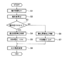
図7は、本実施形態に係る空燃比センサ1により空燃比測定方法を示すフローチャートである。まず、空燃比センサ1及びその周辺回路に電源電圧が供給されると、定電流回路40はポンピングセル20に対して定電流を供給する。そして、図7に示すフローチャートが実行される。
FIG. 7 is a flowchart showing an air-fuel ratio measuring method by the air-
まず、制御部80は、電圧回路50をオフとする(S1)。その後電位差測定
は、第3電極31と第4電極32との電位差を測定する(S2)。なお、ステップS1において電源回路50をオフする理由は、電位差測定時に電圧回路50の電圧が重畳して正確な電位差を検出できなくなってしまう事態を防止するためである。
First, the
次に、制御部80は、ステップS2において測定した電位差が0.5V以上であるかを判断する(S3)。電位差が0.5V以上であると判断した場合(S3:YES)、制御部80は還元雰囲気であると判断して(S4)、電圧回路50の印加電圧を−0.5Vとする(S5)。そして、処理はステップS8に移行する。
Next, the
一方、電位差が0.5V以上でないと判断した場合(S3:NO)、制御部80は酸化雰囲気であると判断して(S6)、電圧回路50の印加電圧を0.5Vとする(S7)。そして、処理はステップS8に移行する。
On the other hand, when it is determined that the potential difference is not 0.5 V or more (S3: NO), the
ステップS8において出力電流測定部60は出力電流を測定する。そして、図7に示す処理は終了する。なお、出力電流の測定後、出力電流の値に基づいて所定の演算部が空燃比を演算することとなる。
In step S8, the output
図8は、本実施形態に係る空燃比センサ1による空燃比と出力電流との相関を示す特性図である。図8に示すように、酸化雰囲気及び還元雰囲気の双方において、出力電流は空燃比に応じてリニアに変化していることがわかる。これにより、本実施形態に係る空燃比センサ1は、酸化雰囲気のみならず還元雰囲気においても測定精度の向上が図れることとなる。
FIG. 8 is a characteristic diagram showing the correlation between the air-fuel ratio and the output current by the air-
このようにして、本実施形態に係る空燃比センサ1及び空燃比測定方法によれば、センサセル30の電極31,32間の電位差を検出し、検出された電位差に応じて、電圧回路50の電圧値を制御する。ここで、本件出願人は、酸化雰囲気におけるセンサセル30の電極間電位差と、還元雰囲気におけるセンサセル30の電極間電位差が異なることを見出した。すなわち、還元雰囲気において一方の電極31の酸素濃度はポンピングセル20側から供給される酸素により酸素濃度が高くなるが、他方の電極32の酸素濃度は還元雰囲気に曝されて酸素濃度が低くなる。このように、電極31,32間において酸素濃度に差が生じる。これにより、電極間電位差が異なることとなり、酸化雰囲気であるか還元雰囲気であるかを判断でき、これに応じて電圧回路50の印加電圧を設定できることとなる。従って、酸化雰囲気においても還元雰囲気においても出力電流がリニアに変化するように電圧回路50の印加電圧を設定でき、還元雰囲気における測定制度について向上させることができる。
Thus, according to the air-
また、電位差測定部70は、電圧回路50からの印加電圧の遮断時においてセンサセル30の電極31,32間の電位差を検出する。このため、電位差検出にあたり印加電圧が電位差に合算してしまい、正確な電位差を検出できなくなってしまう事態を防止することができる。
The potential
また、ポンピングセル20は、ガス律速体10側から順に第1電極21と、固体電解質23と、第2電極22とを順次積層させた積層構造からなるため、簡素の構成により空燃比センサ1を製造等することができる。
The pumping
また、センサセル30は、ガス律速体10側から順に第3電極31と、固体電解質33と、第4電極32とを順次積層させた積層構造からなるため、簡素の構成により空燃比センサ1を製造等することができる。
The
以上、実施形態に基づき本発明を説明したが、本発明は上記実施形態に限られるものではなく、本発明の趣旨を逸脱しない範囲で、変更を加えてもよい。例えば、本実施形態に係る空燃比センサ1において、制御部80は、電位差に基づいて酸化雰囲気であるか還元雰囲気であるかを判断し、判断結果に基づいて電圧回路50の印加電圧を調整しているが、制御部80の構成はこれに限られるものではない。すなわち、制御部80は、酸化雰囲気であるか還元雰囲気であるかを判断する機能を有しておらず、電位差に基づいて電圧回路50の電圧値を調整するアナログ回路等であってもよい。
As described above, the present invention has been described based on the embodiment, but the present invention is not limited to the above embodiment, and may be modified without departing from the gist of the present invention. For example, in the air-
1…空燃比センサ
10…ガス律速体
20…ポンピングセル
21…第1電極
22…第2電極
23…固体電解質(ポンピングセル側固体電解質)
30…センサセル
31…第3電極
32…第4電極
33…固体電解質(センサセル側固体電解質)
40…定電流回路
50…電圧回路
60…出力電流測定部
70…電位差測定部(電位差検出手段)
80…制御部(制御手段)
DESCRIPTION OF
30 ...
40 ... constant
80... Control unit (control means)
Claims (6)
電圧回路から電圧が印加されると共に、前記ポンピングセルによって供給された酸素ガスの濃度と自然拡散により前記ガス律速体に導入されたガスの濃度とに応じた電流を出力可能なセンサセルと、
前記センサセルの電極間の電位差を検出する電位差検出手段と、
前記電位差検出手段により検出された電位差に応じて、前記電圧回路の電圧値を制御する制御手段と、
を備えることを特徴とする空燃比センサ。 A pumping cell for supplying oxygen gas having a concentration corresponding to a constant current supplied from a constant current circuit to a gas rate limiting body;
A sensor cell capable of outputting a current in accordance with the concentration of oxygen gas supplied by the pumping cell and the concentration of gas introduced into the gas rate limiting body by natural diffusion while applying a voltage from a voltage circuit;
A potential difference detecting means for detecting a potential difference between the electrodes of the sensor cell;
Control means for controlling the voltage value of the voltage circuit according to the potential difference detected by the potential difference detection means;
An air-fuel ratio sensor comprising:
ことを特徴とする請求項1に記載の空燃比センサ。 The control means determines that the atmosphere is a reducing atmosphere when the potential difference is equal to or greater than a predetermined value, and sets the voltage value of the voltage circuit according to the reducing atmosphere, and the potential difference is less than a predetermined value. 2. The air-fuel ratio sensor according to claim 1, wherein the air-fuel ratio sensor is determined to be an oxidizing atmosphere and the voltage value of the voltage circuit is set to a voltage value corresponding to the oxidizing atmosphere.
ことを特徴とする請求項1又は請求項2のいずれかに記載の空燃比センサ。 The air-fuel ratio sensor according to claim 1, wherein the potential difference detection unit detects a potential difference between the electrodes of the sensor cell when an applied voltage from the voltage circuit is cut off.
ことを特徴とする請求項1から請求項3のいずれか1項に記載の空燃比センサ。 The pumping cell has a stacked structure in which a first electrode, a pumping cell-side solid electrolyte, and a second electrode are sequentially stacked in order from the gas rate-limiting body side. The air-fuel ratio sensor according to claim 1.
ことを特徴とする請求項1から請求項4のいずれか1項に記載の空燃比センサ。 5. The sensor cell according to claim 1, wherein the sensor cell has a stacked structure in which a third electrode, a sensor cell-side solid electrolyte, and a fourth electrode are sequentially stacked from the gas rate-limiting body side. The air-fuel ratio sensor according to item.
前記センサセルの電極間の電位差を検出する電位差検出工程と、
前記電位差検出工程において検出された電位差に応じて、前記電圧回路の電圧値を制御する制御工程と、
を有することを特徴とする空燃比測定方法。 A pumping cell for supplying oxygen gas having a concentration according to a constant current supplied from a constant current circuit to the gas rate limiting body, a voltage is applied from the voltage circuit, and the concentration of oxygen gas supplied by the pumping cell An air-fuel ratio measuring method for an air-fuel ratio sensor, comprising: a sensor cell capable of outputting a current according to the concentration of gas introduced into the gas rate-limiting body by natural diffusion of the gas-rate-limiting body,
A potential difference detecting step of detecting a potential difference between the electrodes of the sensor cell;
A control step of controlling the voltage value of the voltage circuit according to the potential difference detected in the potential difference detection step;
An air-fuel ratio measuring method comprising:
Priority Applications (1)
| Application Number | Priority Date | Filing Date | Title |
|---|---|---|---|
| JP2009147248A JP5145292B2 (en) | 2009-06-22 | 2009-06-22 | Air-fuel ratio sensor and air-fuel ratio measurement method |
Applications Claiming Priority (1)
| Application Number | Priority Date | Filing Date | Title |
|---|---|---|---|
| JP2009147248A JP5145292B2 (en) | 2009-06-22 | 2009-06-22 | Air-fuel ratio sensor and air-fuel ratio measurement method |
Publications (2)
| Publication Number | Publication Date |
|---|---|
| JP2011002403A JP2011002403A (en) | 2011-01-06 |
| JP5145292B2 true JP5145292B2 (en) | 2013-02-13 |
Family
ID=43560459
Family Applications (1)
| Application Number | Title | Priority Date | Filing Date |
|---|---|---|---|
| JP2009147248A Expired - Fee Related JP5145292B2 (en) | 2009-06-22 | 2009-06-22 | Air-fuel ratio sensor and air-fuel ratio measurement method |
Country Status (1)
| Country | Link |
|---|---|
| JP (1) | JP5145292B2 (en) |
Families Citing this family (3)
| Publication number | Priority date | Publication date | Assignee | Title |
|---|---|---|---|---|
| JP5399303B2 (en) * | 2010-03-23 | 2014-01-29 | 矢崎エナジーシステム株式会社 | Air-fuel ratio detection device |
| JP6952578B2 (en) * | 2017-11-02 | 2021-10-20 | 株式会社東芝 | Oxygen concentration measuring device and oxygen concentration measuring method |
| CN110043379B (en) * | 2019-05-10 | 2024-08-16 | 重庆潍柴发动机有限公司 | Gas control device, system, method and controller |
Family Cites Families (8)
| Publication number | Priority date | Publication date | Assignee | Title |
|---|---|---|---|---|
| JPH0682417A (en) * | 1992-09-03 | 1994-03-22 | Unisia Jecs Corp | Air-fuel ratio sensor |
| JP3326899B2 (en) * | 1993-08-12 | 2002-09-24 | 株式会社豊田中央研究所 | Thin film air-fuel ratio sensor |
| DE4447033C2 (en) * | 1994-12-28 | 1998-04-30 | Bosch Gmbh Robert | Sensor for determining the oxygen content in gas mixtures |
| JP2000206083A (en) * | 1999-01-18 | 2000-07-28 | Ngk Spark Plug Co Ltd | Gas detector and air-fuel ratio measuring method |
| JP2001059833A (en) * | 1999-08-23 | 2001-03-06 | Hitachi Ltd | Exhaust gas concentration detector |
| DE10156248C1 (en) * | 2001-11-15 | 2003-06-18 | Bosch Gmbh Robert | Gas sensor for measuring concentration of component in gas mixture e.g. oxygen in exhaust gas of internal combustion engine, comprises solid electrolyte, diffusion barrier and electrodes |
| JP2007101201A (en) * | 2005-09-30 | 2007-04-19 | Yazaki Corp | Air-fuel ratio sensor and air-fuel ratio detection device |
| JP4989540B2 (en) * | 2008-03-31 | 2012-08-01 | 矢崎総業株式会社 | Air-fuel ratio detection device |
-
2009
- 2009-06-22 JP JP2009147248A patent/JP5145292B2/en not_active Expired - Fee Related
Also Published As
| Publication number | Publication date |
|---|---|
| JP2011002403A (en) | 2011-01-06 |
Similar Documents
| Publication | Publication Date | Title |
|---|---|---|
| JP6469464B2 (en) | Gas sensor | |
| EP2107365B1 (en) | NOx sensor | |
| JP5074358B2 (en) | Gas sensor control device and nitrogen oxide concentration detection method | |
| US11293893B2 (en) | Gas sensor and gas concentration measurement method | |
| EP2406622B1 (en) | Oxygen sensor controller and oxygen sensor control method | |
| JPH1038845A (en) | Nitrogen oxides measuring method | |
| JP2015031604A (en) | Gas sensor | |
| JP2016138775A (en) | Gas sensor | |
| US20130180854A1 (en) | Correction coefficient setting method of gas concentration detection apparatus, gas concentration detection apparatus and gas sensor | |
| US20140332378A1 (en) | Hydrocarbon gas sensor | |
| JP2001155752A (en) | Fuel cell controller | |
| JP5145292B2 (en) | Air-fuel ratio sensor and air-fuel ratio measurement method | |
| ITMI20080293A1 (en) | PROCEDURE FOR OPERATING AN LAMBDA PROBE | |
| US9599598B2 (en) | SOx gas sensor and method of measuring concentration of SOx gas | |
| KR102687211B1 (en) | hydrogen concentration sensor | |
| JP2000009685A (en) | Hydrogen gas sensor, fuel cell system, and method for measuring hydrogen gas concentration | |
| JP4989540B2 (en) | Air-fuel ratio detection device | |
| JP2005121666A (en) | Nox sensor | |
| WO2024075397A1 (en) | Gas sensor and concentration measurement method by means of gas sensor | |
| JP2011033506A (en) | Redox determining sensor, oxygen sensor, redox determining method and method for measuring oxygen concentration of oxygen sensor | |
| JP5103877B2 (en) | Fuel cell system | |
| JP2019056673A (en) | Sensor control device | |
| JP5399303B2 (en) | Air-fuel ratio detection device | |
| JP3882656B2 (en) | Gas concentration measuring method and gas concentration sensor | |
| JP2006071429A (en) | Gas concentration detecting apparatus |
Legal Events
| Date | Code | Title | Description |
|---|---|---|---|
| A621 | Written request for application examination |
Free format text: JAPANESE INTERMEDIATE CODE: A621 Effective date: 20120507 |
|
| A711 | Notification of change in applicant |
Free format text: JAPANESE INTERMEDIATE CODE: A712 Effective date: 20120926 |
|
| RD03 | Notification of appointment of power of attorney |
Free format text: JAPANESE INTERMEDIATE CODE: A7423 Effective date: 20120927 |
|
| RD04 | Notification of resignation of power of attorney |
Free format text: JAPANESE INTERMEDIATE CODE: A7424 Effective date: 20121005 |
|
| A977 | Report on retrieval |
Free format text: JAPANESE INTERMEDIATE CODE: A971007 Effective date: 20121030 |
|
| TRDD | Decision of grant or rejection written | ||
| A01 | Written decision to grant a patent or to grant a registration (utility model) |
Free format text: JAPANESE INTERMEDIATE CODE: A01 Effective date: 20121106 |
|
| A01 | Written decision to grant a patent or to grant a registration (utility model) |
Free format text: JAPANESE INTERMEDIATE CODE: A01 |
|
| A61 | First payment of annual fees (during grant procedure) |
Free format text: JAPANESE INTERMEDIATE CODE: A61 Effective date: 20121126 |
|
| FPAY | Renewal fee payment (event date is renewal date of database) |
Free format text: PAYMENT UNTIL: 20151130 Year of fee payment: 3 |
|
| R150 | Certificate of patent or registration of utility model |
Ref document number: 5145292 Country of ref document: JP Free format text: JAPANESE INTERMEDIATE CODE: R150 Free format text: JAPANESE INTERMEDIATE CODE: R150 |
|
| R250 | Receipt of annual fees |
Free format text: JAPANESE INTERMEDIATE CODE: R250 |
|
| R250 | Receipt of annual fees |
Free format text: JAPANESE INTERMEDIATE CODE: R250 |
|
| R250 | Receipt of annual fees |
Free format text: JAPANESE INTERMEDIATE CODE: R250 |
|
| R250 | Receipt of annual fees |
Free format text: JAPANESE INTERMEDIATE CODE: R250 |
|
| R250 | Receipt of annual fees |
Free format text: JAPANESE INTERMEDIATE CODE: R250 |
|
| R250 | Receipt of annual fees |
Free format text: JAPANESE INTERMEDIATE CODE: R250 |
|
| R250 | Receipt of annual fees |
Free format text: JAPANESE INTERMEDIATE CODE: R250 |
|
| LAPS | Cancellation because of no payment of annual fees |