JP5144807B2 - Optical wavelength converter and coherent light source using the same - Google Patents
Optical wavelength converter and coherent light source using the same Download PDFInfo
- Publication number
- JP5144807B2 JP5144807B2 JP2011512168A JP2011512168A JP5144807B2 JP 5144807 B2 JP5144807 B2 JP 5144807B2 JP 2011512168 A JP2011512168 A JP 2011512168A JP 2011512168 A JP2011512168 A JP 2011512168A JP 5144807 B2 JP5144807 B2 JP 5144807B2
- Authority
- JP
- Japan
- Prior art keywords
- wavelength
- cavity
- servo control
- coherent light
- pump beam
- Prior art date
- Legal status (The legal status is an assumption and is not a legal conclusion. Google has not performed a legal analysis and makes no representation as to the accuracy of the status listed.)
- Expired - Fee Related
Links
Images


Classifications
-
- G—PHYSICS
- G02—OPTICS
- G02F—OPTICAL DEVICES OR ARRANGEMENTS FOR THE CONTROL OF LIGHT BY MODIFICATION OF THE OPTICAL PROPERTIES OF THE MEDIA OF THE ELEMENTS INVOLVED THEREIN; NON-LINEAR OPTICS; FREQUENCY-CHANGING OF LIGHT; OPTICAL LOGIC ELEMENTS; OPTICAL ANALOGUE/DIGITAL CONVERTERS
- G02F1/00—Devices or arrangements for the control of the intensity, colour, phase, polarisation or direction of light arriving from an independent light source, e.g. switching, gating or modulating; Non-linear optics
- G02F1/35—Non-linear optics
- G02F1/3501—Constructional details or arrangements of non-linear optical devices, e.g. shape of non-linear crystals
-
- G—PHYSICS
- G02—OPTICS
- G02F—OPTICAL DEVICES OR ARRANGEMENTS FOR THE CONTROL OF LIGHT BY MODIFICATION OF THE OPTICAL PROPERTIES OF THE MEDIA OF THE ELEMENTS INVOLVED THEREIN; NON-LINEAR OPTICS; FREQUENCY-CHANGING OF LIGHT; OPTICAL LOGIC ELEMENTS; OPTICAL ANALOGUE/DIGITAL CONVERTERS
- G02F1/00—Devices or arrangements for the control of the intensity, colour, phase, polarisation or direction of light arriving from an independent light source, e.g. switching, gating or modulating; Non-linear optics
- G02F1/35—Non-linear optics
- G02F1/353—Frequency conversion, i.e. wherein a light beam is generated with frequency components different from those of the incident light beams
-
- G—PHYSICS
- G02—OPTICS
- G02F—OPTICAL DEVICES OR ARRANGEMENTS FOR THE CONTROL OF LIGHT BY MODIFICATION OF THE OPTICAL PROPERTIES OF THE MEDIA OF THE ELEMENTS INVOLVED THEREIN; NON-LINEAR OPTICS; FREQUENCY-CHANGING OF LIGHT; OPTICAL LOGIC ELEMENTS; OPTICAL ANALOGUE/DIGITAL CONVERTERS
- G02F2203/00—Function characteristic
- G02F2203/15—Function characteristic involving resonance effects, e.g. resonantly enhanced interaction
Abstract
Description
本発明は、光波長変換装置およびそのような装置を用いたコヒーレント光源に関する。 The present invention relates to an optical wavelength converter and a coherent light source using such an apparatus.
種々のレーザ源のなかでも、固体および半導体レーザ源は、エネルギー効率、簡潔性、ロバスト性、コンパクト性、およびコストの点で、極めて好都合な特性を呈している。結果として、レーザの中でも、産業において最も一般的に使用されている。 Of the various laser sources, solid and semiconductor laser sources exhibit very advantageous properties in terms of energy efficiency, simplicity, robustness, compactness, and cost. As a result, among lasers, it is most commonly used in industry.
しかしながら、そのようなレーザ源の多くは、近赤外または可視スペクトルの赤色部分においてしか発光しない。より短い波長(例えば、可視スペクトルの黄色、緑色、または青色範囲、あるいは紫外)での動作のためには、伝統的に、イオンまたは色素レーザなどの装置に頼ることが必要であった。特に、色素レーザは、いくつかの欠点(色素の毒性、動作の不安定性、使用の困難性)を呈しており、結果として最近は使用されなくなってきている。 However, many such laser sources emit only in the near infrared or red portion of the visible spectrum. Traditionally, it has been necessary to rely on equipment such as ion or dye lasers for operation at shorter wavelengths (eg, yellow, green, or blue range of the visible spectrum, or ultraviolet). In particular, dye lasers exhibit several drawbacks (dye toxicity, operational instability, difficulty in use) and as a result have not been used recently.
直接的に可視または紫外において発光するレーザ源の欠点を軽減するために、非線形の光学的効果に基づく全固体のシステムが開発されている。そのようなシステムにおいては、固体レーザ源によって生成される赤外のレーザビーム(「ポンプ」ビームと称される)の周波数が、非線形結晶との相互作用によって2倍にされる(第2高調波の生成(SHG))。変形例においては、2つの別個のポンプビームが、そのような非線形結晶において組み合わせられ、入射ビームの周波数の和に等しい周波数の第3のビームが生成される(和周波数の生成(SFG))。 To alleviate the disadvantages of laser sources that emit directly in the visible or ultraviolet, all-solid systems based on nonlinear optical effects have been developed. In such a system, the frequency of an infrared laser beam (referred to as a “pump” beam) generated by a solid state laser source is doubled by interaction with a nonlinear crystal (second harmonic). Production (SHG)). In a variant, two separate pump beams are combined in such a nonlinear crystal to produce a third beam with a frequency equal to the sum of the frequencies of the incident beams (Generation of Sum Frequency (SFG)).
そのような波長変換システム(または、そのような波長変換システムと同等の方法)の弱点は、それらの効率が多くの場合に低いことにある。 A weakness of such wavelength conversion systems (or methods equivalent to such wavelength conversion systems) is that their efficiency is often low.
最も単純な波長変換の技法は、自由に伝播するポンプビームの軌道に非線形結晶を配置することからなる。実際には、この技法では、入射する光電場の強度が不十分であるため、少なくとも連続波の条件下での変換効率が低すぎる。 The simplest wavelength conversion technique consists of placing a nonlinear crystal in the orbit of a freely propagating pump beam. In practice, this technique has inadequate intensity of the incident photoelectric field, so that the conversion efficiency is at least too low under continuous wave conditions.
変換効率を改善するために、非線形結晶を、ポンプビームと共振する光キャビティの内部に配置することが知られており、光キャビティにおいて、光の強度が、連続波の条件下でも極めて高いレベルに達することができる。 In order to improve the conversion efficiency, it is known to place a nonlinear crystal inside the optical cavity that resonates with the pump beam, where the light intensity is at a very high level even under continuous wave conditions. Can reach.
第2高調波の生成システムにおいては、使用される光キャビティを、赤外レーザ源の共振器形成部分によって構成することが可能である。この可能性が、Coherent社によって、同社の「Verdi」(商標)という製品系列のレーザにおいて、成功裏に使用されている。しかしながら、この技術は、実現および一般化が困難である。 In the second harmonic generation system, the optical cavity used can be constituted by the resonator forming part of the infrared laser source. This possibility has been successfully used by Coherent in its "Verdi" (TM) product line of lasers. However, this technique is difficult to implement and generalize.
使用において汎用性の高い代案は、非線形結晶を、エキザルテーションキャビティ(exaltation cavity)と称される外部の共振器に配置することからなる。能動式または受動式の安定化システムが、変換効率を最適にすべく、キャビティをポンプレーザビームとの共振状態に保つように機能し、これにより変換効率が50%に達することができ、50%を超えることさえ可能である。例として、以下の刊行物を参照することができる。 A highly versatile alternative in use consists of placing the nonlinear crystal in an external resonator called an exhalation cavity. An active or passive stabilization system functions to keep the cavity in resonance with the pump laser beam to optimize the conversion efficiency, which allows the conversion efficiency to reach 50%, 50% It is even possible to exceed. By way of example, reference can be made to the following publications:
・J.D.Vance、C.Y.She、およびH.Moosmuller、「Continuous−wave,all solid−state,single−frequency 400mW source at 589nm based on doubly resonant sum−frequency mixing in a monolithic lithium niobate resonator」、App.Opt.37、4891〜4896頁、1998年(残余のキャビティ内吸収によって引き起こされる熱光学的効果による受動的な安定化、40%を超える効率)。 ・ J. D. Vance, C.I. Y. She, and H.C. Moosmuller, “Continuous-wave, all solid-state, single-frequency 400 mW source at 589 nm based on doubly the number of quasi Opt. 37, 4891-4896, 1998 (passive stabilization due to thermo-optic effects caused by residual intracavity absorption, efficiencies above 40%).
このような受動的なサーボ制御が、共振のフリンジにおいて最大限に不安定であり、結晶における熱拡散によって通過帯が1キロヘルツ程度に限られることに、注意すべきである。A.Douillet、J.J.Zondy、A.Yelisseyev、S.Lobanov、L.Isaenkoによる論文「Stability and frequency tuning of thermally−loaded cw AgGaS2 optical parametric oscillators」、J.Opt.Soc.Am.B 16、1481〜1498頁(1999年)を参照されたい。 It should be noted that such passive servo control is maximally unstable at the resonant fringes and the passband is limited to about 1 kilohertz due to thermal diffusion in the crystal. A. Douillet, J.M. J. et al. Zondy, A.M. Yelisseyev, S .; Lobanov, L.M. Isaenko's paper “Stability and frequency tuning of thermal-loaded cw AgGaS 2 optical parametric oscillators”, J. Am. Opt. Soc. Am. B 16, 1481-1498 (1999).
・Joshua C.Bienfang、Craig A.Denman、Brent W.Grime、Paul D.Hillman、Gerald T.Moore、およびJohn M.Telle、「20W of continuous−wave sodium D2 resonance radiation from sum−frequency generation with injection−lockedlasers」、Opt.Lett.28、2219〜2221頁、2003年(能動的な安定化、55%を超える効率)。 ・ Joshua C. Bienfang, Craig A. Denman, Brent W. Grime, Paul D.C. Hillman, Gerald T. Moore, and John M. Telle, "20W of continuous-wave sodium D 2 resonance radiation from sum-frequency generation with injection-lockedlasers ", Opt. Lett. 28, 2219-2221, 2003 (active stabilization, efficiencies above 55%).
・文献US7035297。
E.Jurdikらによる論文「Performance optimizationof an external enhancement resonator foroptical second−harmonic generation」、J.Opt.Soc.Am.B 19、1660〜1667頁、2002年が、第2高調波の生成のためのエンハンスメントキャビティの最適化を検討しており、53%の変換効率が観察されている。
-Document US7035297.
E. Jurdik et al., “Performance optimization of an external enhancement resonant second-harmonic generation”, J. Am. Opt. Soc. Am. B 19, pp. 1660-1667, 2002 discusses optimization of enhancement cavities for second harmonic generation and a conversion efficiency of 53% has been observed.
大部分の環境においては、キャビティの周波数が、キャビティの入り口カプラによって反射されるポンプレーザの一部分またはミラーのうちの1つを透過するキャビティ内パワーの小さな一部分のいずれかから生成される誤差信号を入力として受け取るサーボ制御ループによって、能動的な方法で安定化される。第2の代案は、キャビティがサーボ制御されていないときに検出器の飽和を回避するために、「黒色背景」における動作を可能にする。最も幅広く使用されている安定化の技法は、以下である。 In most environments, the frequency of the cavity produces an error signal generated from either a portion of the pump laser reflected by the cavity entrance coupler or a small portion of the intracavity power that is transmitted through one of the mirrors. It is stabilized in an active way by a servo control loop that receives as input. The second alternative allows operation in a “black background” to avoid detector saturation when the cavity is not servo controlled. The most widely used stabilization technique is:
・Pound−Drever−Hall法:Eric D.Blackによる論文「An introduction to Pound−Drever−Hall laser frequency stabilization」、Am.J.Phys.69、79〜87頁、2001年を参照。 Pound-Drever-Hall method: Eric D. Black's paper “An introduction to Pound-Drever-Hall laser frequency stabilization”, Am. J. et al. Phys. 69, 79-87, 2001.
・「AM−FM」法。キャビティの長さを共振の近傍において圧電セラミックによって軽く変調させ(振幅変調、すなわち「AM」をもたらし)、同時検出によって信号を復調して、共振フリンジの導関数に比例する誤差信号を生成することからなる技法。あるいは、レーザの周波数に変調を加えてもよい(周波数変調、すなわち「FM」)。 ・ "AM-FM" method. Lightly modulate the cavity length near the resonance with a piezoceramic (resulting in amplitude modulation, or “AM”), and demodulate the signal with simultaneous detection to produce an error signal proportional to the derivative of the resonant fringe A technique consisting of Alternatively, the laser frequency may be modulated (frequency modulation, or “FM”).
・Hansch−Couillaud法:T.W.HanschおよびB.Couillaudの「Laser frequency stabilization by polarization spectroscopy on a reflecting reference cavity」、Opt.Commun.35、441(1980年)を参照。 Hansch-Couilleud method: T.W. W. Hansch and B.H. Couillaud, “Laser frequency stabilization by polarization spectroscopic on a reflecting reference cavity”, Opt. Commun. 35, 441 (1980).
いわゆる「チルトロッキング」または「意図的ミスアライメント」法など、他の技法も提案されている。D.A.Shaddokらによる論文「Frequency locking a laser to an optical cavity using spatial mode interference」、Opt.Lett.24、1499(1999年)を参照されたい。 Other techniques have also been proposed, such as so-called “tilt locking” or “intentional misalignment” methods. D. A. Shaddok et al., “Frequency locking a laser to an optical cavity using spatial mode interference,” Opt. Lett. 24, 1499 (1999).
典型的には、2つの波長調節機構が使用される。一方が「高速チャネル」であり、高速であるがダイナミックレンジが狭く、ほぼ白色のスペクトルを有する高周波の変動(機械的および音響的な振動、レーザの周波数および振幅の雑音、・・・)を補正し、他方が「低速チャネル」であり、より低速であるがダイナミックレンジがより広く、低い周波数または極めて低い周波数の変動(例えば、熱ドリフトなどの長期のドリフト、・・・)を補正する。反射または透過のいずれかにてキャビティから導出される誤差信号が、増幅され、次いで積分され(比例−積分(PI)サーボ制御)、おそらくは微分され(比例−積分−微分(PID)サーボ制御)、次いで上述の調節機構を制御するために使用される。 Typically, two wavelength tuning mechanisms are used. One is a “high-speed channel” that corrects high-frequency fluctuations (mechanical and acoustic vibrations, laser frequency and amplitude noise,...) With high speed but narrow dynamic range and almost white spectrum. However, the other is a “slow channel” that is slower but has a wider dynamic range and corrects for low or very low frequency fluctuations (eg, long-term drift such as thermal drift,...). The error signal derived from the cavity in either reflection or transmission is amplified and then integrated (proportional-integral (PI) servo control) and possibly differentiated (proportional-integral-derivative (PID) servo control). It is then used to control the adjustment mechanism described above.
2つの別々のポンプビームが使用される場合(周波数和の生成)、キャビティが、弱い方のビームに合わせて調節された状態に保たれる一方で、より強い方のポンプレーザの放射波長が、キャビティの共振周波数へとさらにサーボ制御される(上述の文献US7035297参照)。 If two separate pump beams are used (frequency sum generation), the cavity is kept tuned for the weaker beam while the emission wavelength of the stronger pump laser is The servo is further controlled to the resonance frequency of the cavity (see the above-mentioned document US7035297).
本発明は、能動的に安定化される外部キャビティを有している形式の光波長変換システムの効率の改善を追求する。 The present invention seeks to improve the efficiency of optical wavelength conversion systems of the type having an external cavity that is actively stabilized.
光キャビティを能動的に安定化させるための一般的な技法は、波長変換結晶の存在によって引き起こされる非線形な影響を考慮していない。しかしながら、本発明者らは、結晶における非線形な動態が、波長変換が最大の効率で生じる共振状態の付近でキャビティの内部に蓄えられるパワーを減少させることによって、上述のサーボ制御の仕組みを大いに妨げるという事実に気が付いた。そして、本発明者らは、とりわけこの影響が十分な方法では考慮されていないという事実ゆえに、従来技術において公知のシステムの変換効率が制約されていることを発見した。 The general technique for actively stabilizing the optical cavity does not take into account the non-linear effects caused by the presence of the wavelength converting crystal. However, we find that nonlinear dynamics in the crystal greatly hinder the servo control mechanism described above by reducing the power stored inside the cavity near the resonant state where wavelength conversion occurs with maximum efficiency. I noticed the fact. The inventors have then found that the conversion efficiency of systems known in the prior art is limited, in particular due to the fact that this effect is not taken into account in a sufficient way.
本発明は、従来技術のこの欠点の改善を可能にし、90%にもなりうる変換効率の達成を可能にする。 The present invention makes it possible to remedy this drawback of the prior art and to achieve conversion efficiencies that can be as high as 90%.
より正確には、本発明は、第1のポンプビームと称される第1の波長の第1のコヒーレント光ビームを少なくとも入力として受け取り、出口ビームと称される前記第1の波長とは異なる波長の少なくとも1つのコヒーレント光ビームを放射するように構成されており、光キャビティと、前記光キャビティの内部に配置され、前記第1のポンプビームと相互作用して前記出口ビームを生成するために適している光学的に非線形な媒体と、前記光キャビティの共振モードを前記第1の波長にサーボ制御するためのサーボ制御システムと、を備える波長変換用の光学装置であって、前記サーボ制御システムが、前記第1の波長において前記キャビティに蓄えられたエネルギーを表わす第1の信号および前記キャビティによって放射される前記出口ビームのパワーを表わす第2の信号を入力として受け取って、前記光キャビティの共振波長をサーボ制御するためのサーボ制御信号を出力するように構成されていることを特徴とする光学装置を提供する。 More precisely, the present invention receives as input at least a first coherent light beam of a first wavelength, referred to as a first pump beam, and a wavelength different from the first wavelength, referred to as an exit beam. Is configured to emit at least one coherent light beam, and is disposed within the optical cavity and suitable for interacting with the first pump beam to generate the exit beam. An optically nonlinear medium, and a servo control system for servo-controlling the resonance mode of the optical cavity to the first wavelength, wherein the servo control system comprises: A first signal representative of energy stored in the cavity at the first wavelength and the exit beam radiated by the cavity. Receiving a second signal representative of the power of the beam as the input, provides an optical apparatus characterized by being configured to the resonance wavelength of the optical cavity and outputs a servo control signal for servo control.
特に、前記サーボ制御システムを、前記第1の信号および第2の信号の線形結合から誤差信号を生成するように構成することが可能である。 In particular, the servo control system can be configured to generate an error signal from a linear combination of the first signal and the second signal.
前記サーボ制御システムは、Pound−Drever−Hall方式、AM−FM方式、「チルトロッキング」または意図的ミスアライメント方式、およびHansch−Couillaud方式に基づくサーボ制御の仕組みに基づくことが可能である。 The servo control system may be based on a servo control mechanism based on the Pound-Drever-Hall method, AM-FM method, “tilt locking” or intentional misalignment method, and the Hansch-Coillaud method.
さらに、本発明の装置を、第2のポンプビームと称される前記第1の波長とは異なる第2の波長の第2のコヒーレント光ビームを入力として受け取るように構成することが可能であり、前記光学的に非線形な媒体が、前記第1のポンプビームおよび第2のポンプビームと相互作用して、和または差の周波数の前記出口ビームを生成することができる。 Furthermore, the apparatus of the present invention can be configured to receive as input a second coherent light beam of a second wavelength different from the first wavelength, referred to as a second pump beam, The optically non-linear medium can interact with the first and second pump beams to produce the exit beam at a sum or difference frequency.
さらに本発明は、上述のような光波長変換装置と、前記第1のポンプビームを生成するためのレーザ源とを備えているコヒーレント光源を提供する。 Furthermore, the present invention provides a coherent light source comprising the optical wavelength conversion device as described above and a laser source for generating the first pump beam.
所望により、本発明は、典型的には前記第1のポンプビームのパワーよりも大きいパワーを呈する前記第2のポンプビームを生成するための第2のレーザ源をさらに備えてもよい。 If desired, the present invention may further comprise a second laser source for generating the second pump beam that typically exhibits a power greater than the power of the first pump beam.
そのような状況において、本発明の光源は、前記第2のポンプビームの波長を前記キャビティの共振波長にサーボ制御するための第2のサーボ制御システムをさらに備えることが可能である。好都合には、前記第2のサーボ制御システムを、前記出口ビームの光パワーを最大にするような方法で前記第2のポンプビームの波長をサーボ制御するように構成することが可能である。 In such a situation, the light source of the present invention may further include a second servo control system for servo-controlling the wavelength of the second pump beam to the resonance wavelength of the cavity. Conveniently, the second servo control system can be configured to servo control the wavelength of the second pump beam in such a way as to maximize the optical power of the exit beam.
本発明の特定の実施形態においては、前記第2のレーザ源が、2つの波長調節機構を呈することができ、すなわち「高速」な第1の機構と、該第1の機構に比べてより狭い通過帯およびより広いダイナミックレンジを呈する「低速」な第2の機構とを呈することができ、前記第2のサーボ制御システムが、前記出口ビームのパワーが第1のしきい値を下回って低下したときに、前記低速な波長調節機構を阻止および再初期化して、前記高速な機構だけをサーボ制御に使用し、前記出口ビームのパワーが前記第1のしきい値よりも高い第2のしきい値を超えるとき、前記低速な機構による制御を再開させるように構成される。 In a particular embodiment of the invention, the second laser source can present two wavelength tuning mechanisms, ie a “fast” first mechanism and a narrower one compared to the first mechanism. A second mechanism that exhibits a passband and a wider dynamic range, and the second servo control system reduces the power of the exit beam below a first threshold. Sometimes, blocking and re-initializing the slow wavelength tuning mechanism, using only the fast mechanism for servo control, and a second threshold where the power of the exit beam is higher than the first threshold. When the value is exceeded, the control by the low speed mechanism is resumed.
所望により、本発明の光源は、前記第1のポンプビームの波長を外部の基準へとサーボ制御するための第3のサーボ制御システムをさらに備えてもよい。 If desired, the light source of the present invention may further comprise a third servo control system for servo-controlling the wavelength of the first pump beam to an external reference.
本発明の他の特徴、詳細、および利点は、あくまでも例として提示される添付図面を参照しつつ行われる以下の説明を検討することによって、明らかになる。 Other features, details, and advantages of the present invention will become apparent upon review of the following description made with reference to the accompanying drawings, which are presented by way of example only.
図1のコヒーレント光源は、光学システムおよび3つのサーボ制御ループを備えている。図中、光ビームの経路が、実線によって表わされており、電気信号の経路が、破線によって表わされている。 The coherent light source of FIG. 1 includes an optical system and three servo control loops. In the figure, the path of the light beam is represented by a solid line, and the path of the electrical signal is represented by a broken line.
光学システムは、それぞれ波長λ1およびλ2の2つのポンプビームを放射する2つのポンプレーザL1およびL2を備えている。例として、ポンプレーザL1およびL2は、単一縦横モード(TEM00)で連続的に発振する2つのネオジムドープしたイットリウム・アルミニウム・ガーネット(Nd:YAG)レーザであってよい。第1のポンプレーザの波長λ1は、1319.2ナノメートル(nm)であってよく、第2のポンプレーザの波長λ2は、1064.6nmであってよい。 The optical system comprises two pump lasers L1 and L2 that emit two pump beams of wavelengths λ 1 and λ 2 , respectively. As an example, the pump lasers L1 and L2 may be two neodymium-doped yttrium aluminum garnet (Nd: YAG) lasers that oscillate continuously in a single longitudinal and transverse mode (TEM 00 ). The wavelength λ 1 of the first pump laser may be 1319.2 nanometers (nm), and the wavelength λ 2 of the second pump laser may be 1064.6 nm.
2つのポンプレーザは、少なくともナノメートル程度のスペクトル範囲にわたって波長を調節することが可能である。典型的には、各々のレーザが、2つの波長調節機構を有している。すなわち、その一方が「高速チャネル」を構成し、高速であるがダイナミックレンジが限られており、他方が「低速チャネル」を構成し、より低速であるがより広いダイナミックレンジ「低速チャネル」を有する。 The two pump lasers can be tuned over a spectral range of at least nanometers. Each laser typically has two wavelength tuning mechanisms. That is, one of them constitutes a “fast channel” and is fast but has a limited dynamic range, and the other constitutes a “slow channel” and has a slower but wider dynamic range “slow channel”. .
以下では、第1のポンプレーザL1の放射強度が、第2のレーザL2の放射強度よりも低いと考える。すなわち、第1のレーザが、和周波数の光源の放射強度を制限する。従来からの方法で、非線形変換効率が、光源によって出力される光子束と第1のポンプレーザの光子束の比として定義される。 In the following, it is considered that the radiation intensity of the first pump laser L1 is lower than the radiation intensity of the second laser L2. That is, the first laser limits the radiation intensity of the sum frequency light source. Conventionally, the nonlinear conversion efficiency is defined as the ratio of the photon flux output by the light source to the photon flux of the first pump laser.
これらの2つのポンプビームが、ダイクロイックミラーMCによって組み合わせられ、非線形結晶CNLが配置されている共振器CE(「エキザルテーションキャビティ」)へと入射される。図中、2つのポンプビームの軌跡が、判別可能にするために互いに離れた平行線によって表わされているが、実際には、両方のビームは、結晶の内部で相互作用できるように重なり合っている。 These two pump beams are combined by a dichroic mirror MC and incident on a resonator CE (“excitation cavity”) in which a nonlinear crystal CNL is arranged. In the figure, the trajectories of the two pump beams are represented by parallel lines that are separated from each other in order to be distinguishable, but in practice both beams overlap so that they can interact inside the crystal. Yes.
キャビティCEは、4つのミラーM1、M2、M3、およびM4によって構成された「蝶ネクタイ」状の一方向性のリングキャビティである。第1のミラーM1は、入り口カプラとして機能するように波長λ1およびλ2において半透過性であり、典型的には、これらの波長における反射率が、正確な値はポンプビームの公称の強度の関数として決まる(上述のE.Jurdikらによる文献を参照)が、95%〜99%の範囲にある。他の3つのミラーM2、M3、およびM4は、通常は99.5%を上回る極めて高い反射率を呈する。第4のミラーM4は、非線形結晶において生成される出力ビームの波長(λs)において透過性であり、したがって出口カプラとして機能する。キャビティCEの共振の波長を、第2のミラーM2が取り付けられた圧電アクチュエータTPZによってキャビティCEの長さを変更することで、調節することが可能である。2つの圧電アクチュエータ(一方が高速であるが比較的ダイナミックレンジが小さく、他方がより低速であるがより広いダイナミックレンジを有する)を、同じミラーまたは2つの別々のミラーを制御すべく有することが好ましい。 The cavity CE is a “bow tie” -shaped unidirectional ring cavity constituted by four mirrors M1, M2, M3 and M4. The first mirror M1 is translucent at wavelengths λ 1 and λ 2 to function as an entrance coupler, and typically the reflectivity at these wavelengths is an accurate value that is the nominal intensity of the pump beam. (See the literature by E. Jurdik et al. Above) is in the range of 95% to 99%. The other three mirrors M2, M3, and M4 exhibit very high reflectivity, typically above 99.5%. The fourth mirror M4 is transmissive at the wavelength (λ s ) of the output beam generated in the nonlinear crystal and thus functions as an exit coupler. The wavelength of resonance of the cavity CE can be adjusted by changing the length of the cavity CE by the piezoelectric actuator TPZ to which the second mirror M2 is attached. It is preferable to have two piezoelectric actuators (one fast but relatively small dynamic range and the other slower but wider dynamic range) to control the same mirror or two separate mirrors .
非線形結晶CNLは、従来技術において公知の任意の種類であってよく、光源の動作波長へと適合させることができる。例えば、周期的に分極したKTP(KTiOPO4)であってよい。例えば熱電モジュールを用いた結晶の温度の調節が、所望の波長における位相の調節(より正確には、周期的に分極した材料における擬似的な位相の調節)を得るように機能する。 The nonlinear crystal CNL can be of any type known in the prior art and can be adapted to the operating wavelength of the light source. For example, it may be periodically poled KTP (KTiOPO 4 ). For example, adjusting the temperature of the crystal using a thermoelectric module functions to obtain a phase adjustment at the desired wavelength (more precisely, a pseudo phase adjustment in a periodically polarized material).
非線形のKTP結晶は、2つのポンプビームの最大の焦点に一致するように配置される。 A non-linear KTP crystal is placed to coincide with the maximum focus of the two pump beams.
結晶CNLでの2つのポンプビームの混合が、コヒーレント過程が関係しているため、ポンプビームの周波数の和に等しい周波数にあって、同じ空間および時間コヒーレンス特性を有している出口ビームを生み出す。この例では、出口波長が582.9nmであり、したがって可視スペクトルの黄色部分に位置している。 The mixing of the two pump beams in the crystalline CNL results in an exit beam that is at a frequency equal to the sum of the pump beam frequencies and has the same spatial and temporal coherence characteristics because of the coherent process involved. In this example, the exit wavelength is 582.9 nm and is therefore located in the yellow part of the visible spectrum.
効率的な波長変換を得るために、キャビティCEにおけるポンプビームの強度を最大にすることが必要である。これを行うために、公知の方法で、キャビティが、弱い方のレーザ源L1の放射波長へとサーボ制御され、この理由で、弱い方のレーザ源L1は「マスター」レーザと称される。サーボ制御は、ミラーM2のアクチュエータTPZを制御する第1のサーボ制御ループBA1によって実行される。その後、第2のポンプレーザL2、すなわち「スレーブ」レーザが、第2のサーボ制御ループBA2によってキャビティの波長にサーボ制御される。この制御の構造そのものは、公知である。例えば、上述の文献US7035297を参照されたい。 In order to obtain efficient wavelength conversion, it is necessary to maximize the intensity of the pump beam in the cavity CE. To do this, the cavity is servo-controlled in a known manner to the emission wavelength of the weaker laser source L1, and for this reason the weaker laser source L1 is referred to as the “master” laser. The servo control is executed by a first servo control loop BA1 that controls the actuator TPZ of the mirror M2. Thereafter, the second pump laser L2, or “slave” laser, is servo controlled to the wavelength of the cavity by a second servo control loop BA2. This control structure itself is known. For example, see the above-mentioned document US7035297.
所望により、「マスター」レーザL1を、光源からの出口における波長を安定させるために、第3のサーボ制御ループBA3によって外部の分光基準RSへとさらにサーボ制御してもよい。 If desired, the “master” laser L1 may be further servo-controlled to an external spectral reference RS by a third servo control loop BA3 in order to stabilize the wavelength at the exit from the light source.
従来技術において公知の波長変換システムにおいては、エキザルテーションキャビティCEをマスターレーザL1へとサーボ制御するための第1のサーボ制御ループBA1が、キャビティの入り口カプラ(ミラーM1)によって反射させられる第1のポンプビームの一部分を検出することによって生成される誤差信号をゼロに近く保つような方法で設計されている。変形例においては、キャビティ内に収容され、このキャビティの残りのミラーのうちの1つを通って漏れ出る第1のポンプビームの波長のパワーの一部分を利用することが可能である。この第2の選択肢が、図1に示されている。ミラーM3を通ってキャビティから漏れ出る光が、波長λ1の成分を分離するためにダイクロイックミラーF0によってフィルタ処理され、波長λ1の成分がセンサ(光検出器)PD1によって検出される。 In a wavelength conversion system known in the prior art, a first servo control loop BA1 for servo-controlling the extraction cavity CE to the master laser L1 is reflected by a cavity entrance coupler (mirror M1). It is designed in such a way as to keep the error signal generated by detecting a part of the pump beam close to zero. In a variant, it is possible to make use of a fraction of the power at the wavelength of the first pump beam housed in a cavity and leaking through one of the remaining mirrors of this cavity. This second option is shown in FIG. Light leaked from the cavity through the mirror M3 is filtered by a dichroic mirror F0 to separate wavelength lambda 1 of the component, the component of the wavelength lambda 1 is detected by a sensor (optical detector) PD1.
図2Aでは、破線の曲線I’M3(λ1)が、キャビティから「漏れ」る波長λ1の放射の強度が、非線形結晶CNLが存在しないキャビティC3の共振周波数νcにどのように依存するのかを示している。この曲線は、ローレンツ型を有しており、νc=ν1(ここでν1は、第1のポンプビームの周波数)に極めて明確なピークを呈している。周波数の調節が、キャビティとレーザL1との間で実行されるとき、波長λ1のキャビティに蓄えられるエネルギーが最大になり、結果として漏れの強度も最大になる。 In FIG. 2A, the dashed curve I ′ M3 (λ 1 ) shows how the intensity of the radiation of wavelength λ 1 “leaking” from the cavity depends on the resonant frequency ν c of the cavity C3 where there is no nonlinear crystal CNL. Is shown. This curve has a Lorentzian shape and exhibits a very clear peak at ν c = ν 1 (where ν 1 is the frequency of the first pump beam). Regulation of frequency, when executed between the cavity and the laser L1, the maximum stored energy is transferred to the wavelength lambda 1 of the cavity, the intensity of leakage as a result also becomes maximum.
このようにして、キャビティCEを、理論的には、I’M3(λ1)の値を最大にすることによってサーボ制御することが可能である。 In this way, the cavity CE can theoretically be servo-controlled by maximizing the value of I ′ M3 (λ 1 ).
実際には、信号I’M3(λ1)をサーボ制御ループによって上述のように使用することが、その最大点を中心とする対称な形状ゆえに、不可能であることが従来技術から知られている。したがって、I’M3(λ1)のνcに対する導関数に比例する誤差信号を生成する技法が提案されている。最も広く知られた方法は、Pound−Drever−Hall法である。この技法によれば、第1のポンプビームが、高周波で動作する発振器OLによって制御されるポッケルスセルMPによって位相変調され、その後、検出器PD1からの信号が、発振器OLによって生成される高周波信号との混合によってコヒーレントに復調させられ(高周波ミキサMX)、最後に、ミキサMXによって出力される信号がフィルタ処理(フィルタF1)され、必要とされる誤差信号がもたらされる。Pound−Drever−Hall法の基礎をなす理論は、上述のEric D.Blackによる論文に詳しく記載されている。 In practice, it is known from the prior art that the signal I ′ M3 (λ 1 ) cannot be used as described above by the servo control loop because of its symmetrical shape about its maximum point. Yes. Therefore, techniques have been proposed for generating an error signal that is proportional to the derivative of I ′ M3 (λ 1 ) with respect to ν c . The most widely known method is the Pound-Drever-Hall method. According to this technique, the first pump beam is phase-modulated by a Pockels cell MP controlled by an oscillator OL operating at high frequencies, after which the signal from the detector PD1 is combined with the high-frequency signal generated by the oscillator OL. Are coherently demodulated (high frequency mixer MX) and finally the signal output by the mixer MX is filtered (filter F 1 ) to provide the required error signal. The theory underlying the Pound-Drever-Hall method is described by Eric D., supra. It is described in detail in a paper by Black.
実際には、非線形結晶CNLが、周波数変換ゆえにキャビティCEに損失を持ち込む。これらの損失は、変換効率が高くなるほど増加し、したがってキャビティの調節状態が満足されるときに最大になる。さらに図2Aを参照すると、実線の曲線I’M3(λ1)が、極めて効率的な波長変換が存在する場合に、キャビティCEから「漏れ」る波長λ1の放射の強度について、キャビティCEの共振周波数νcの関数としての依存性を示している。非線形変換によって持ち込まれる損失が、I’M3(λ1)に「穴を掘って」いることを、見て取ることができる。本発明者らは、この事実を考慮し、このような条件下において光検出器PD1からの信号にPound−Drever−Hall法(あるいは、任意の同等な方法)を適用することによって得られる誤差信号が、もはやキャビティのサーボ制御に適していないと推論した。 In practice, the nonlinear crystal CNL introduces a loss in the cavity CE due to frequency conversion. These losses increase with higher conversion efficiency and are therefore maximized when the cavity conditioning is satisfied. Still referring to FIG. 2A, the solid curve I ′ M3 (λ 1 ) shows the intensity of radiation at wavelength λ 1 that “leaks” from cavity CE in the presence of very efficient wavelength conversion. The dependence of the resonance frequency ν c as a function is shown. It can be seen that the loss introduced by the non-linear transformation is “drilling” in I ′ M3 (λ 1 ). In view of this fact, the present inventors consider an error signal obtained by applying the Pound-Drever-Hall method (or any equivalent method) to the signal from the photodetector PD1 under such conditions. However, it was inferred that it was no longer suitable for cavity servo control.
本発明は、これまで認識されていなかったこの従来技術の問題に対する技術的解決策を提供する。 The present invention provides a technical solution to this prior art problem that was not previously recognized.
本発明によれば、サーボ制御ループBA1の誤差信号が、キャビティから漏れ出る第1のポンプビームの一部分のみから生成されるのではなく、和周波数においてこのキャビティによって放射される光パワーも考慮して生成される。これを行うために、ビームスプリッタLP2が、光源からの出口ビームの経路に配置され、このビームの一部分を第2の光検出器PD2へと照射する。 According to the invention, the error signal of the servo control loop BA1 is not generated from only a part of the first pump beam leaking out of the cavity, but also taking into account the optical power emitted by this cavity at the sum frequency. Generated. In order to do this, a beam splitter LP2 is arranged in the path of the exit beam from the light source and irradiates a part of this beam onto the second photodetector PD2.
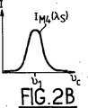
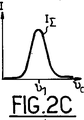
図2Bでは、曲線IM4(λs)が、波長λsにおいて放射されるパワーが、キャビティCEの共振周波数νcにどのように依存するのかを示している。この曲線は、調節状態νc=ν1に中心を有する極めて明確なピークを呈している。本発明の基礎となる考え方は、曲線IM4(λs)のピークを、非線形変換によって曲線IM3(λ1)の曲線のピークに掘られた穴を「埋める」ために使用することにある。図2Cでは、曲線IΣが、信号IM4(λs)およびIM3(λ1)を(適切な係数によって重み付けした後で)足すことによって得られる信号を表わしている。 In FIG. 2B, the curve I M4 (λ s ) shows how the power radiated at the wavelength λ s depends on the resonance frequency ν c of the cavity CE. This curve exhibits a very clear peak centered on the adjusted state ν c = ν 1 . The idea underlying the present invention is to use the peak of the curve I M4 (λ s ) to “fill” the hole dug into the peak of the curve I M3 (λ 1 ) by a non-linear transformation. . In FIG. 2C, the curve I Σ represents the signal obtained by adding the signals I M4 (λ s ) and I M3 (λ 1 ) (after weighting with appropriate coefficients).
具体的には、本発明の光源においては、第1の光検出器PD1によって生成される信号s1および第2の光検出器PD2によって生成される信号s2が、係数a1およびa2によって重み付けされ、次いで和ノードΣにおいて足し合わせられる。次いで、ノードΣからの和信号ssが、コヒーレントな方法で復調されるべく、ミキサMXへと入力としてもたらされ、低域通過フィルタ(図示せず)によってフィルタ処理される。このようにして得られた誤差信号seが、ループフィルタF1へと入力され、圧電アクチュエータTPZを制御するサーボ制御信号saが生成される。 Specifically, in the light source of the present invention, the signal s 2 generated by the first signal s 1 and the second is produced by the light detector PD1 of the photodetector PD2 is, the coefficients a 1 and a 2 Weighted and then summed at sum node Σ. The sum signal s s from node Σ is then provided as an input to mixer MX to be demodulated in a coherent manner and is filtered by a low pass filter (not shown). The error signal s e thus obtained is input to the loop filter F 1 and a servo control signal s a for controlling the piezoelectric actuator TPZ is generated.
和周波数の生成がコヒーレント現象であり、ポンプビームの位相変調が和ビームλ2においても見られるため、Pound−Drever−Hall法を信号ssへと適用可能であることに気付くことが興味深い。 It is interesting to note that the Pound-Drever-Hall method can be applied to the signal s s because the generation of the sum frequency is a coherent phenomenon and the phase modulation of the pump beam is also seen in the sum beam λ 2 .
第1の制御ループの動作を、Pound−Drever−Hall法に関して上述した。しかしながら、従来技術において公知の他のサーボ制御技法(特に、Hansch−Couillaud法)も、使用することが可能である。いずれにせよ、原理は、第1のポンプビームの波長においてキャビティに蓄えられたエネルギーを表わす第1の信号と、和周波数においてキャビティ内に生成される光パワーを表わす第2の信号との線形結合から、誤差信号を生成することにある。 The operation of the first control loop has been described above with respect to the Pound-Dever-Hall method. However, other servo control techniques known in the prior art (especially the Hansch-Couloulou method) can also be used. In any case, the principle is a linear combination of a first signal representing the energy stored in the cavity at the wavelength of the first pump beam and a second signal representing the optical power produced in the cavity at the sum frequency. From this, an error signal is generated.
Pound−Drever−Hall式の技法が使用される場合、一般的には、第1のポンプレーザのスペクトルへと持ち込まれる側波帯が、キャビティが調節されたときにキャビティの(常に有限の幅である)共振帯の範囲内に位置するように、(1MHz程度の)比較的低い位相変調周波数νLOを使用することが好都合である。しかしながら、この条件は必須ではない。 When the Pound-Drever-Hall technique is used, the sidebands introduced into the spectrum of the first pump laser are generally limited to the cavity (always with a finite width when the cavity is adjusted). It is advantageous to use a relatively low phase modulation frequency ν LO (on the order of 1 MHz) so that it lies within the resonance band. However, this condition is not essential.
キャビティCEの「スレーブ」レーザL2の第2のサーボ制御ループBA2は、従来技術において公知の任意の種類であってよく、特にPound−Drever−Hall式の技法(第1のサーボ制御ループによって使用される周波数変調とは異なる周波数変調による)に基づくことができる。しかしながら、図面が難しくならないように、第2のループにおいて使用されるポッケルスセル、高周波発振器、およびミキサ/復調器は、図示しない。したがって、図には、非線形変換の効率を最大にするような方法で第2のポンプ光源L2を制御する制御信号を生成するために、第2の光検出器PD2からの信号s2の取得およびループフィルタF2による信号のフィルタ処理だけを示す。 The second servo control loop BA2 of the “slave” laser L2 of the cavity CE may be of any kind known in the prior art, in particular the Pound-Drever-Hall type technique (used by the first servo control loop). Based on a different frequency modulation). However, the Pockels cell, high frequency oscillator, and mixer / demodulator used in the second loop are not shown so that the drawing is not difficult. Thus, the figure shows the acquisition of the signal s 2 from the second photodetector PD2 and the generation of a control signal for controlling the second pump light source L2 in such a way as to maximize the efficiency of the non-linear conversion. Only signal filtering by the loop filter F2 is shown.
しかしながら、本発明者らは、極めて効率的な波長変換が、第2のサーボ制御ループの動作にも困難を生じさせることに気が付いた。 However, the inventors have realized that extremely efficient wavelength conversion also creates difficulties for the operation of the second servo control loop.
キャビティの共振幅は、キャビティの損失に依存する。残念ながら、波長変換によって持ち込まれる損失は、比例的に、スレーブレーザよりもマスターレーザ(より弱い)においてはるかに大きい。したがって、第2のサーボ制御ループは、第1のループよりも「脆弱」であるが、それでも第1のループを追跡しなければならない。したがって、一時的な外乱(振動、電源の不安定、・・・)の結果として共振条件に大きすぎる相違が生じる場合に、スレーブレーザL2のサーボ制御信号が飽和する恐れが存在する。 The resonant width of the cavity depends on the cavity loss. Unfortunately, the loss introduced by wavelength conversion is proportionally much greater in the master laser (weaker) than in the slave laser. Thus, the second servo control loop is “weaker” than the first loop, but must still track the first loop. Therefore, there is a possibility that the servo control signal of the slave laser L2 is saturated when the resonance condition is too large as a result of temporary disturbance (vibration, power supply instability,...).
この欠点を軽減するために、本発明は、レーザL2の2つの波長調節機構(比較的高速であるがダイナミックレンジが限られている第1の機構と、より低速であるがより広いダイナミックレンジを呈する第2の機構)の存在を利用することを提案する。 To alleviate this drawback, the present invention provides two wavelength adjustment mechanisms for the laser L2 (a first mechanism that is relatively fast but has a limited dynamic range, and a slower but wider dynamic range). We propose to use the existence of a second mechanism).
通常は、サーボ制御は、両方の機構(「高速」および「低速」)に同時に作用することによって実行される。しかしながら、和周波数の出口パワーが第1のしきい値を下回って低下するときには、ループが、制御信号の飽和を避けるべく、前記低速機構をブロックし、再初期化するために、サンプルホールド回路を使用する。ループがPID方式である場合には、ループが開かれ、ループに含まれる積分器が、短絡させることによってゼロへとリセットされる。対照的に、高速サーボ制御機構の制御は、好ましくは比例の方法のみにて続けられる。出力ビームのパワーが第2のしきい値(前記第1のしきいよりも大きい)を超えて再び増加すると、レーザL2の低速サーボ制御機構が再開される。 Normally, servo control is performed by acting on both mechanisms (“high speed” and “low speed”) simultaneously. However, when the sum frequency exit power falls below the first threshold, the loop may use a sample and hold circuit to block and reinitialize the low speed mechanism to avoid saturation of the control signal. use. If the loop is PID, the loop is opened and the integrator contained in the loop is reset to zero by shorting. In contrast, control of the high speed servo control mechanism is preferably continued only in a proportional manner. When the power of the output beam increases again above a second threshold (greater than the first threshold), the low speed servo control mechanism of laser L2 is resumed.
マスターレーザL1の放射波長を安定させる任意の第3のサーボ制御ループBA3については、特に述べるべきことはない。任意の第3のサーボ制御ループBA3は、図1が難しくならないように簡略化した様相(スペクトル基準RS、ビームスプリッタLP1、およびループフィルタF3)にて図示されている。 The optional third servo control loop BA3 that stabilizes the emission wavelength of the master laser L1 should not be mentioned in particular. The optional third servo control loop BA3 is illustrated in a simplified form (spectral reference RS, beam splitter LP1, and loop filter F3) so that FIG. 1 does not become difficult.
本発明を、特定の例を参照して上述したが、多数の変形例が可能である。 Although the present invention has been described above with reference to specific examples, many variations are possible.
特に、それらの変形例は、以下に関係することが可能である。
・ポンプレーザの種類(特に、固体または半導体レーザであってよい)。
・ポンプおよび光源の放射波長。
・第1のループのサーボ制御の方式。従来技術において公知の任意の方式(Hansch−Couillaud法、意図的ミスアライメント)が、本発明の実現に適すると考えられる。
・波長変換に使用される非線形媒体。
In particular, these variants can relate to:
• The type of pump laser (especially it may be a solid or semiconductor laser).
• Radiation wavelength of pump and light source.
・ First loop servo control method. Any scheme known in the prior art (Hansch-Couillaud method, intentional misalignment) is considered suitable for the realization of the present invention.
-Non-linear media used for wavelength conversion.
さらに、以上においては、非変性の周波数和の状況のみを検討したが、本発明は、二次の(あるいは、さらに高次の)高調波の生成(単一ポンプレーザが使用され、差周波数が生成される)またはパラメトリック増幅など、他の非線形の周波数変換効果を使用することも可能である。 Furthermore, in the above, only the situation of the non-denatured frequency sum has been considered, but the present invention generates a second-order (or higher-order) harmonic (a single pump laser is used and the difference frequency is It is also possible to use other non-linear frequency conversion effects, such as generated) or parametric amplification.
Claims (11)
・光キャビティ(CE)と、
・前記光キャビティの内部に配置され、前記第1のポンプビームと相互作用して前記出口ビームを生成するために適している光学的に非線形な媒体(CNL)と、
・前記光キャビティの共振モードを前記第1の波長にサーボ制御するためのサーボ制御システム(BA1)と、
を備える波長変換用の光学装置であって、
前記サーボ制御システムが、前記第1の波長において前記キャビティに蓄えられたエネルギーを表わす第1の信号(s1)および前記キャビティによって放射される前記出口ビームのパワーを表わす第2の信号(s2)を入力として受け取って、前記光キャビティの共振波長をサーボ制御するためのサーボ制御信号(sa)を出力するように構成されていることを特徴とする光学装置。A first coherent light beam of a first wavelength (λ 1 ) called a first pump beam is received as at least an input of a wavelength (λ s ) different from the first wavelength called an exit beam. Configured to emit at least one coherent light beam;
・ Optical cavity (CE),
An optically nonlinear medium (CNL) disposed within the optical cavity and suitable for interacting with the first pump beam to produce the exit beam;
A servo control system (BA1) for servo-controlling the resonant mode of the optical cavity to the first wavelength;
An optical device for wavelength conversion comprising:
A first signal (s 1 ) representing the energy stored in the cavity at the first wavelength and a second signal (s 2) representing the power of the exit beam emitted by the cavity. ) As an input and output a servo control signal (s a ) for servo-controlling the resonance wavelength of the optical cavity.
・Pound−Drever−Hall方式と、
・AM−FM方式と、
・「チルトロッキング」または意図的ミスアライメント方式と、
・およびHansch−Couillaud方式と、
に基づくサーボ制御の仕組みに基づいている請求項1または2に記載の光学装置。The servo control system (BA1)
・ Pound-Drever-Hall method,
・ AM-FM method
・ "Tilt locking" or intentional misalignment method,
・ And Hansch-Coulouloud method,
The optical device according to claim 1, which is based on a servo control mechanism based on the above.
前記第1のポンプビームを生成するための第1のレーザ源(L1)と、
前記第2のポンプビームを生成するための第2のレーザ源(L2)と、
を備えるコヒーレント光源。An optical wavelength converter according to claim 4,
A first laser source (L1) for generating the first pump beam;
A second laser source (L2) for generating the second pump beam;
A coherent light source.
前記第2のサーボ制御システムが、前記出口ビームのパワーが第1のしきい値を下回って低下したときに、前記低速な波長調節機構を阻止および再初期化して、前記高速な機構だけをサーボ制御に使用し、前記出口ビームのパワーが前記第1のしきい値よりも高い第2のしきい値を超えるとき、前記低速な機構による制御を再開させるように構成されている請求項6〜9のいずれかに記載のコヒーレント光源。The second laser source presents two wavelength tuning mechanisms: a “fast” first mechanism and a “slow” exhibiting a narrower passband and a wider dynamic range than the first mechanism. And the second mechanism,
The second servo control system blocks and re-initializes the slow wavelength tuning mechanism when the power of the exit beam drops below a first threshold, and servos only the fast mechanism. 7. Used for control, and configured to resume control by the slow mechanism when the power of the exit beam exceeds a second threshold value that is higher than the first threshold value. The coherent light source according to any one of 9.
Applications Claiming Priority (3)
| Application Number | Priority Date | Filing Date | Title |
|---|---|---|---|
| FR0803153A FR2932285B1 (en) | 2008-06-06 | 2008-06-06 | OPTICAL WAVE LENGTH CONVERTING DEVICE, AND COHERENT LIGHT SOURCE USING SUCH A DIPOSITIVE |
| FR0803153 | 2008-06-06 | ||
| PCT/FR2009/000635 WO2009147317A1 (en) | 2008-06-06 | 2009-06-02 | Optical wavelength conversion device, and coherent light source using same |
Publications (2)
| Publication Number | Publication Date |
|---|---|
| JP2011522296A JP2011522296A (en) | 2011-07-28 |
| JP5144807B2 true JP5144807B2 (en) | 2013-02-13 |
Family
ID=40289431
Family Applications (1)
| Application Number | Title | Priority Date | Filing Date |
|---|---|---|---|
| JP2011512168A Expired - Fee Related JP5144807B2 (en) | 2008-06-06 | 2009-06-02 | Optical wavelength converter and coherent light source using the same |
Country Status (6)
| Country | Link |
|---|---|
| US (1) | US8717665B2 (en) |
| EP (1) | EP2291711B1 (en) |
| JP (1) | JP5144807B2 (en) |
| AT (1) | ATE555416T1 (en) |
| FR (1) | FR2932285B1 (en) |
| WO (1) | WO2009147317A1 (en) |
Families Citing this family (6)
| Publication number | Priority date | Publication date | Assignee | Title |
|---|---|---|---|---|
| WO2015093210A1 (en) * | 2013-12-20 | 2015-06-25 | ソニー株式会社 | Light source device and method for converting wavelength |
| JP6508059B2 (en) * | 2013-12-24 | 2019-05-08 | ソニー株式会社 | Control device, control method, and program |
| JP6444489B2 (en) * | 2015-03-06 | 2018-12-26 | ギガフォトン株式会社 | Solid-state laser system and laser apparatus for exposure apparatus |
| US10378006B2 (en) | 2017-04-19 | 2019-08-13 | The Florida International University Board Of Trustees | Near-infrared ray exposure system for biological studies |
| GB2563005B (en) * | 2017-05-23 | 2021-04-21 | M Squared Lasers Ltd | Nonlinear crystal |
| IT201800007429A1 (en) * | 2018-07-23 | 2020-01-23 | METHOD AND APPARATUS TO MAINTAIN THE CONDITION OF SIMULTANEOUS RESONANCE OF TWO DISTINCT ELECTROMAGNETIC FIELDS IN A CAVITY |
Family Cites Families (11)
| Publication number | Priority date | Publication date | Assignee | Title |
|---|---|---|---|---|
| JPH07254744A (en) * | 1994-03-15 | 1995-10-03 | Sony Corp | Laser light generator |
| US6005878A (en) * | 1997-02-19 | 1999-12-21 | Academia Sinica | Efficient frequency conversion apparatus for use with multimode solid-state lasers |
| US6404786B1 (en) * | 1997-08-25 | 2002-06-11 | Sony Corporation | Laser beam generating apparatus |
| JP3885511B2 (en) * | 2001-04-11 | 2007-02-21 | ソニー株式会社 | Laser light generating apparatus and method |
| JP3885529B2 (en) * | 2001-08-06 | 2007-02-21 | ソニー株式会社 | Laser light generator |
| US7110426B2 (en) * | 2001-08-06 | 2006-09-19 | Sony Corporation | Laser beam generating apparatus |
| US6751010B1 (en) * | 2003-04-23 | 2004-06-15 | Itt Manufacturing Enterprises, Inc. | Low finesse, tri-etalon, optical parametric oscillator |
| JP4365135B2 (en) * | 2003-05-26 | 2009-11-18 | 株式会社島津製作所 | Solid state laser equipment |
| US7035297B1 (en) * | 2004-01-30 | 2006-04-25 | The United States Of America As Represented By The Secretary Of The Air Force | Continuous wave sodium beacon excitation source |
| JP2005327839A (en) * | 2004-05-13 | 2005-11-24 | Miyachi Technos Corp | Method and apparatus for generating harmonic laser |
| DE102005015497B4 (en) * | 2005-03-31 | 2008-10-16 | Nlg-New Laser Generation Gmbh | Stabilization of cascaded optical resonators |
-
2008
- 2008-06-06 FR FR0803153A patent/FR2932285B1/en not_active Expired - Fee Related
-
2009
- 2009-06-02 US US12/996,496 patent/US8717665B2/en not_active Expired - Fee Related
- 2009-06-02 AT AT09757693T patent/ATE555416T1/en active
- 2009-06-02 WO PCT/FR2009/000635 patent/WO2009147317A1/en active Application Filing
- 2009-06-02 EP EP09757693A patent/EP2291711B1/en not_active Not-in-force
- 2009-06-02 JP JP2011512168A patent/JP5144807B2/en not_active Expired - Fee Related
Also Published As
| Publication number | Publication date |
|---|---|
| ATE555416T1 (en) | 2012-05-15 |
| EP2291711A1 (en) | 2011-03-09 |
| FR2932285A1 (en) | 2009-12-11 |
| WO2009147317A1 (en) | 2009-12-10 |
| US20110267681A1 (en) | 2011-11-03 |
| EP2291711B1 (en) | 2012-04-25 |
| JP2011522296A (en) | 2011-07-28 |
| FR2932285B1 (en) | 2010-06-11 |
| US8717665B2 (en) | 2014-05-06 |
Similar Documents
| Publication | Publication Date | Title |
|---|---|---|
| KR100283829B1 (en) | Optical device, laser light source and method of manufacturing laser device and optical device | |
| US5796761A (en) | High efficiency solid state raman laser system | |
| JP5144807B2 (en) | Optical wavelength converter and coherent light source using the same | |
| US5027360A (en) | High power continuous wave injection-locked solid state laser | |
| JP3885511B2 (en) | Laser light generating apparatus and method | |
| US6724788B1 (en) | Method and device for generating radiation with stabilized frequency | |
| KR20080088440A (en) | Laser light generating apparatus | |
| US6285691B1 (en) | Laser light generating method and apparatus | |
| US9690165B2 (en) | Generator of at least three coherent laser beams in the infrared and visible domain | |
| US20060176916A1 (en) | Laser resonator and frequency-converted laser | |
| JP2010534355A (en) | Intensity modulation in wavelength-converted optical packages | |
| JP3931235B2 (en) | Reciprocating optical modulator | |
| JP3351212B2 (en) | Pulse light source | |
| JP3884404B2 (en) | Laser equipment | |
| JP4945934B2 (en) | Optical system, inspection device, processing device and measuring device | |
| JP3971342B2 (en) | Laser light source and laser projection apparatus | |
| JP3884402B2 (en) | Laser equipment | |
| JP3884405B2 (en) | Laser equipment | |
| JP2000261101A (en) | Wavelength converting device | |
| JP3884403B2 (en) | Laser equipment | |
| JP4226851B2 (en) | Nonlinear optical crystal element and coherent light generator | |
| JP4156644B2 (en) | Laser equipment | |
| Han et al. | Efficient frequency doubling at 776 nm in a ring cavity | |
| JP3884401B2 (en) | Laser light source and optical disk apparatus | |
| Knight et al. | Frequency doubling of a fibre-amplified 1083 nm DBR laser |
Legal Events
| Date | Code | Title | Description |
|---|---|---|---|
| A621 | Written request for application examination |
Free format text: JAPANESE INTERMEDIATE CODE: A621 Effective date: 20120515 |
|
| A977 | Report on retrieval |
Free format text: JAPANESE INTERMEDIATE CODE: A971007 Effective date: 20121023 |
|
| TRDD | Decision of grant or rejection written | ||
| A01 | Written decision to grant a patent or to grant a registration (utility model) |
Free format text: JAPANESE INTERMEDIATE CODE: A01 Effective date: 20121030 |
|
| A01 | Written decision to grant a patent or to grant a registration (utility model) |
Free format text: JAPANESE INTERMEDIATE CODE: A01 |
|
| A61 | First payment of annual fees (during grant procedure) |
Free format text: JAPANESE INTERMEDIATE CODE: A61 Effective date: 20121122 |
|
| FPAY | Renewal fee payment (event date is renewal date of database) |
Free format text: PAYMENT UNTIL: 20151130 Year of fee payment: 3 |
|
| R150 | Certificate of patent or registration of utility model |
Ref document number: 5144807 Country of ref document: JP Free format text: JAPANESE INTERMEDIATE CODE: R150 Free format text: JAPANESE INTERMEDIATE CODE: R150 |
|
| R250 | Receipt of annual fees |
Free format text: JAPANESE INTERMEDIATE CODE: R250 |
|
| R250 | Receipt of annual fees |
Free format text: JAPANESE INTERMEDIATE CODE: R250 |
|
| R250 | Receipt of annual fees |
Free format text: JAPANESE INTERMEDIATE CODE: R250 |
|
| R250 | Receipt of annual fees |
Free format text: JAPANESE INTERMEDIATE CODE: R250 |
|
| R250 | Receipt of annual fees |
Free format text: JAPANESE INTERMEDIATE CODE: R250 |
|
| LAPS | Cancellation because of no payment of annual fees |