JP5138931B2 - Double layer roll boots - Google Patents
Double layer roll boots Download PDFInfo
- Publication number
- JP5138931B2 JP5138931B2 JP2006526172A JP2006526172A JP5138931B2 JP 5138931 B2 JP5138931 B2 JP 5138931B2 JP 2006526172 A JP2006526172 A JP 2006526172A JP 2006526172 A JP2006526172 A JP 2006526172A JP 5138931 B2 JP5138931 B2 JP 5138931B2
- Authority
- JP
- Japan
- Prior art keywords
- boot seal
- layer
- inner layer
- boot
- outer layer
- Prior art date
- Legal status (The legal status is an assumption and is not a legal conclusion. Google has not performed a legal analysis and makes no representation as to the accuracy of the status listed.)
- Expired - Fee Related
Links
Images


Classifications
-
- F—MECHANICAL ENGINEERING; LIGHTING; HEATING; WEAPONS; BLASTING
- F16—ENGINEERING ELEMENTS AND UNITS; GENERAL MEASURES FOR PRODUCING AND MAINTAINING EFFECTIVE FUNCTIONING OF MACHINES OR INSTALLATIONS; THERMAL INSULATION IN GENERAL
- F16J—PISTONS; CYLINDERS; SEALINGS
- F16J3/00—Diaphragms; Bellows; Bellows pistons
- F16J3/04—Bellows
- F16J3/041—Non-metallic bellows
-
- F—MECHANICAL ENGINEERING; LIGHTING; HEATING; WEAPONS; BLASTING
- F16—ENGINEERING ELEMENTS AND UNITS; GENERAL MEASURES FOR PRODUCING AND MAINTAINING EFFECTIVE FUNCTIONING OF MACHINES OR INSTALLATIONS; THERMAL INSULATION IN GENERAL
- F16D—COUPLINGS FOR TRANSMITTING ROTATION; CLUTCHES; BRAKES
- F16D3/00—Yielding couplings, i.e. with means permitting movement between the connected parts during the drive
- F16D3/84—Shrouds, e.g. casings, covers; Sealing means specially adapted therefor
- F16D3/843—Shrouds, e.g. casings, covers; Sealing means specially adapted therefor enclosed covers
- F16D3/845—Shrouds, e.g. casings, covers; Sealing means specially adapted therefor enclosed covers allowing relative movement of joint parts due to the flexing of the cover
-
- F—MECHANICAL ENGINEERING; LIGHTING; HEATING; WEAPONS; BLASTING
- F16—ENGINEERING ELEMENTS AND UNITS; GENERAL MEASURES FOR PRODUCING AND MAINTAINING EFFECTIVE FUNCTIONING OF MACHINES OR INSTALLATIONS; THERMAL INSULATION IN GENERAL
- F16J—PISTONS; CYLINDERS; SEALINGS
- F16J3/00—Diaphragms; Bellows; Bellows pistons
- F16J3/04—Bellows
- F16J3/041—Non-metallic bellows
- F16J3/042—Fastening details
-
- F—MECHANICAL ENGINEERING; LIGHTING; HEATING; WEAPONS; BLASTING
- F16—ENGINEERING ELEMENTS AND UNITS; GENERAL MEASURES FOR PRODUCING AND MAINTAINING EFFECTIVE FUNCTIONING OF MACHINES OR INSTALLATIONS; THERMAL INSULATION IN GENERAL
- F16J—PISTONS; CYLINDERS; SEALINGS
- F16J3/00—Diaphragms; Bellows; Bellows pistons
- F16J3/04—Bellows
- F16J3/041—Non-metallic bellows
- F16J3/043—Non-metallic bellows with particular means for limiting wear
Description
本発明は、エラストマーシールに関し、より具体的にはジョイントをシールするためのブーツシールに関する。 The present invention relates to elastomer seals, and more particularly to boot seals for sealing joints.
エラストマーブーツは主として、互いに連接することができかつより具体的には同時に回転する2つの部品をシールするために使用される。これらの部品は、ジョイントを構成する。典型的な用途は、等速及びユバーサル形式のジョイントをシールすることに関連する。この目的のために、一般的により小さい直径を有する円筒形部分を備えたブーツが、第1のジョイント構成部品に結合されたシャフト上に差込まれ、またより大きい直径を有する環状部分が、直接に又は中間要素を介して第2のジョイント構成部品に接続される。最初に述べた円筒形部分と、より大きい直径を有する環状部分との間には、壁が延びている。壁は、ロールブーツの場合には円環体の半分の形状を有し、また折曲げ状ブーツの場合にはベローズ形状を有する。2つのジョイント構成部品が互いに連接運動を行うと、壁の曲率半径は山形の内側で減少し、山形の外側で増大する。ジョイントが連接状態で回転するとき、ロールブーツ壁の湾曲の変化は円周全体にわたって移動し、その結果、ブーツ壁の各点は、完全な360度回転の間に湾曲最大値と湾曲最小値を通過してブーツ壁の屈曲を引き起こすようになる。屈曲はまた、ブーツの各回転において重力及び遠心力によっても発生する。 Elastomeric boots are primarily used to seal two parts that can be articulated together and more specifically rotate simultaneously. These parts constitute a joint. Typical applications relate to sealing constant velocity and universal joints. For this purpose, a boot with a cylindrical part, generally having a smaller diameter, is plugged onto a shaft coupled to the first joint component and an annular part having a larger diameter is directly Or via an intermediate element to the second joint component. A wall extends between the cylindrical portion first mentioned and the annular portion having a larger diameter. The wall has the shape of a half of a torus in the case of roll boots and the bellows shape in the case of bent boots. As the two joint components articulate with each other, the radius of curvature of the wall decreases inside the chevron and increases outside the chevron. When the joint rotates in an articulated state, the change in roll boot wall curvature moves around the entire circumference, so that each point on the boot wall has its maximum and minimum curve values during a full 360 degree rotation. Pass through and cause the boot wall to bend. Bending also occurs due to gravity and centrifugal forces at each rotation of the boot.
ブーツは内側屈曲作用を受け、それによりブーツの温度の上昇が生じる。この温度上昇により、ブーツ材料は化学的及び熱的攻撃の増大に曝され、ブーツの劣化が加速される。また温度の上昇によって、外部及び内部流体環境にブーツシールが曝されることによって生じる化学反応が増大し、ブーツ壁の材料を加速度的に劣化させる。 The boot undergoes an inward bending action, which causes an increase in boot temperature. This temperature increase exposes the boot material to increased chemical and thermal attack and accelerates boot degradation. Also, the increased temperature increases the chemical reaction that occurs when the boot seal is exposed to the external and internal fluid environment, causing accelerated degradation of the boot wall material.
ブーツ壁の材料はまた、外部及び内部壁面における流体接触のために劣化する。ブーツの外面は、大気条件に接触しかつ曝されて、材料が風化、化学的劣化、その他の形態の劣化の作用を受ける。ブーツの内面は、ジョイントグリースに接触しかつ曝されて、化学的及び他の形態の劣化を受ける。両方の環境に適した材料を選択することにより、ブーツ壁の劣化を最小にすることができる。 The boot wall material also degrades due to fluid contact at the outer and inner walls. The outer surface of the boot is exposed to and exposed to atmospheric conditions and the material is subject to weathering, chemical degradation, and other forms of degradation. The inner surface of the boot contacts and is exposed to joint grease and undergoes chemical and other forms of degradation. By selecting materials suitable for both environments, boot wall degradation can be minimized.
また、ブーツの極度の屈曲により、材料は応力を受ける。ブーツが応力が掛かっていない状態にある場合、フィルム保護層は、ゴムのような状態で材料上に留まることになる。フィルム層がない状態では、材料は、オゾン及び酸素のような成分への環境露出により引き起こされる化学反応やエラストマー結合破壊によってより攻撃されやすくなる。結合破壊の1つの形態は、切断として知られる現象に至る。切断は、材料結合がポリマー鎖に沿って破壊されるような劣化の形態であり、シールの効果のないブーツにする引裂き型の現象を生じる。他の有害な現象は、特定の環境露出に対して材料が不適切に選択された場合に発生し、機械的強度やシール有効性の低下をもたらす Also, the material is stressed by extreme bending of the boot. When the boot is in an unstressed state, the film protective layer will remain on the material in a rubbery state. In the absence of a film layer, the material is more susceptible to attack by chemical reactions and elastomer bond breakage caused by environmental exposure to components such as ozone and oxygen. One form of bond breaking leads to a phenomenon known as cleavage. Cutting is a form of degradation in which material bonds are broken along the polymer chain, resulting in a tear-type phenomenon that results in a boot with no sealing effect. Other detrimental phenomena occur when materials are improperly selected for specific environmental exposures, resulting in reduced mechanical strength and seal effectiveness
ブーツ構造は一般的に、単一材料によるものである。材料は、その用途において最良の機械的特性を得ながら外部及び内部の環境露出からの最良の保護を与えるように選択される。外部又は内部環境のいずれかにより適した材料を選択することによって、材料の一方の面はその環境からの最適な保護が劣ったままむき出しにしておかれる。別の選択は、外部及び内部環境の両方に対してある程度耐性がある材料を選択することである。しかしながら、これは、ブーツの両面を攻撃及び劣化に対してむき出しのままにするので、理想的なものではない。 The boot structure is generally a single material. The material is selected to provide the best protection from external and internal environmental exposure while obtaining the best mechanical properties for the application. By selecting a material that is more suitable for either the external or internal environment, one side of the material is exposed with less optimal protection from that environment. Another option is to select a material that is somewhat resistant to both the external and internal environment. However, this is not ideal because it leaves both sides of the boot exposed to attack and degradation.
両面が連続的又は間欠的に異なる流体に曝される場合に、ブーツ壁の外面及び内面を劣化から保護する方法を入手することは有益であると言える。 It would be beneficial to have a method for protecting the outer and inner surfaces of the boot wall from degradation when both surfaces are exposed to different fluids either continuously or intermittently.
本発明は、異なるエラストマー材料で製造された外部壁を有するブーツシールを提供する。外層材料はオゾンのような外部流体に対して耐性があり、また内層材料はグリースのような内部流体に対して耐性がある。この発明で記載したエラストマー材料には、高分子弾性体である材料が考えられる。異なるエラストマー材料は、異なるエラストマー化学物質群、同一のエラストマー化学物質群又はあらゆる繊維強化エラストマー群或いはそれらのあらゆる組合せとすることができる。エラストマー群は、熱可塑性エラストマー、ゴム、その他のゴム状均等物を含むことができる。 The present invention provides a boot seal having an outer wall made of different elastomeric materials. The outer layer material is resistant to an external fluid such as ozone, and the inner layer material is resistant to an internal fluid such as grease. The elastomer material described in this invention can be a material that is a polymer elastic body. The different elastomeric materials can be different elastomeric chemical groups, the same elastomeric chemical group or any fiber reinforced elastomer group or any combination thereof. The group of elastomers can include thermoplastic elastomers, rubber, and other rubbery equivalents.
本発明の1つの実施態様は、その各々が異なっている2つの層を備えたブーツシールである。ブーツシールは、第1の端部と、第2の端部と、第1の端部及び第2の端部間に延びる本体とを有する。本体は、耐環境性材料で作られた外層と耐グリース性材料で作られた内層とを有する。 One embodiment of the present invention is a boot seal with two layers, each of which is different. The boot seal has a first end, a second end, and a body extending between the first end and the second end. The body has an outer layer made of an environment resistant material and an inner layer made of a grease resistant material.
本発明の別の実施態様は、異なるエラストマー材料で作られた内層と外層を有する射出成形ブーツシールを含むジョイントシールを提供する。各層は、それが曝される流体環境との適合性がある。このことにより、化学、環境、温度露出によって生じる劣化が殆どない状態でブーツシールのより長い寿命が得られることになる。 Another embodiment of the present invention provides a joint seal including an injection molded boot seal having an inner layer and an outer layer made of different elastomeric materials. Each layer is compatible with the fluid environment to which it is exposed. This results in a longer boot seal life with little degradation caused by chemical, environmental or temperature exposure.
さらに、射出成形によって二重層を有するブーツシールを製造する方法を提供する。1つの例では、ブーツシールはデュアル射出成形される。本発明によるブーツシールを射出成形するための別の実施態様では、環境適合性及び耐食特性を有するエラストマーで外層の射出成形を行う。次に、内層が、外層上に射出成形される。内層は、グリースとの適合性がありかつグリースに対して耐食性があるエラストマー材料を含む。デュアル射出成形することによって、2つの環境との材料適合性を有するブーツ壁が形成される。射出成形を使用することの付随的な利点は、この方式でブーツシールを製造するときに、寸法安定性と材料ボンディングが最適な状態で生じることである。 Further provided is a method of manufacturing a boot seal having a double layer by injection molding. In one example, the boot seal is dual injection molded. In another embodiment for injection molding a boot seal according to the present invention, the outer layer is injection molded with an elastomer having environmental compatibility and corrosion resistance. Next, the inner layer is injection molded onto the outer layer. The inner layer includes an elastomeric material that is compatible with the grease and is corrosion resistant to the grease. Dual injection molding forms a boot wall that is material compatible with the two environments. An additional advantage of using injection molding is that dimensional stability and material bonding occur optimally when manufacturing boot seals in this manner.
本発明の他の利点及び特徴もまた、以下の詳細な説明及び特許請求の範囲を読むことにより、また添付図面を参照することにより明らかになるであろう。 Other advantages and features of the present invention will become apparent upon reading the following detailed description and claims, and upon reference to the accompanying drawings.
次に、本発明をさらに完全に理解するために、添付図面により詳細に示しかつ本発明の例として下記に説明した実施形態を参照されたい。 For a more complete understanding of the present invention, reference is now made to the embodiments illustrated in more detail in the accompanying drawings and described below as examples of the present invention.
図において、同一の参照符号は同様の要素を示す。図において、図示した二重層ブーツシールは、ジョイント構成部品が互いに対して移動するようなあらゆるジョイント形式の構成をシールすることができる。典型的なジョイントには、ジョイント部品が周期的ベースで互い対して移動するようになっている等速ユニバーサルジョイント又は他の同様のジョイントが含まれる。本発明のブーツシールは定速ユニバーサルジョイントをシールするための方法及び装置に関して説明するが、本発明は、他の屈曲シャフトシールに適用しかつ利用することもできる。以下の説明においては、幾つかの構成の実施形態において様々なパラメータ及び構成部品を説明している。これら特定のパラメータ及び構成部品は、例として示すものであり、限定することを意味するものではない。 In the figures, identical reference numerals indicate similar elements. In the figure, the illustrated double layer boot seal can seal any joint type configuration such that the joint components move relative to each other. Typical joints include constant velocity universal joints or other similar joints in which the joint components are adapted to move relative to each other on a periodic basis. Although the boot seal of the present invention will be described with respect to a method and apparatus for sealing a constant speed universal joint, the present invention can also be applied and utilized with other bent shaft seals. In the following description, various parameters and components are described in several configuration embodiments. These specific parameters and components are shown by way of example and are not meant to be limiting.
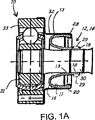
図1Aは、例示的なジョイント組立体における本発明の1つの実施形態による二重層ロールブーツの長手方向断面図を示す。ブーツシール12は、ブーツシール壁13を含む。この例のブーツシール12は、エラストマーで成形されたロールブーツ14である。本発明の実施形態によると、ブーツシール12は、内層15と外層17とを有する状態で形成される。ロールブーツは、ジョイント10をシールした状態で示す。ロールブーツ14は、第1の端部18においてクランプ29によってジョイント10のシャフト30に固定され、また第2の端部20においてクリンプ部分28によってカバー32に固定される。シャフト30は、ジョイント10の内側ジョイント部品31に結合される。カバー32は、ジョイント10の外側ジョイント部品33に結合される。内側ジョイント部品31は、ボールケージ内に保持された複数のトルク伝達ボールによって外側ジョイント部品33に連結される。従って、ロールブーツ14は、第1の端部18を第2の端部20に接続して、ジョイント10をシールするブーツシール壁13を有する。図示するようなこのジョイント10の実施形態は、等速ジョイントである。勿論、本発明によるロールブーツはまた、他の等速ジョイント構成やユニバーサルジョイント構成をシールするのに使用することもできる。
FIG. 1A shows a longitudinal cross-sectional view of a dual layer roll boot according to one embodiment of the present invention in an exemplary joint assembly. The boot seal 12 includes a
図1Bは、例示的なジョイント組立体における本発明の別の実施形態による二重層折曲げ状ブーツの長手方向断面図を示す。ブーツシール12は、ブーツシール壁13を含む。この例におけるブーツシール12は、エラストマーで成形された折曲げ状ブーツ16である。本発明の実施形態によると、ブーツシール12は、内層15と外層17とを有する状態で形成される。折曲げ状ブーツは、ジョイント10をシールした状態で示す。折曲げ状ブーツ16は、第1の端部18においてクランプ29によってジョイント10のシャフト30に固定され、また第2の端部20においてクランプ28によってカバー32に固定される。シャフト30はジョイント10の内側ジョイント31に結合される。カバー32はジョイント10の外側ジョイント33に結合される。内側ジョイント31は、ボールケージ内に保持された複数のトルク伝動ボールによって外側ジョイント33に連結される。従って、折曲げ状ブーツ16は、第1の端部18を第2の端部20に接続してジョイント10をシールするブーツシール壁13を有する。図示するようなこのジョイント10の実施形態は、等速ジョイントである。勿論、本発明によるブーツシールはまた、他の等速ジョイント構成及びユニバーサルジョイント構成をシールするのに使用することもできる。
FIG. 1B shows a longitudinal cross-sectional view of a double-layer folded boot according to another embodiment of the present invention in an exemplary joint assembly. The boot seal 12 includes a
ロールブーツであれ折曲げ状ブーツであれ、ブーツシールは、クランピング、クリンピング又は他のシール方法によってジョイントに取付けられる。ブーツシールは、ジョイント全体を覆ってシールを形成し、このシールが、外部の大気からシールすることによってジョイントを環境から保護し、またジョイント内にグリースをシールする。ブーツシール壁は、2つの流体適合層15、17を備え、各層15、17の材料が、動作する環境における劣化に対して耐性があるので、より長い寿命を有する。従って、殆どのケースにおいて、内層15は耐グリース性の層であり、また外層17は耐オゾン性の層である。ブーツシール壁の各層15、17の材料は、グリース及びオゾン露出を含む最も不利な環境からの保護を強化するように選択される。さらに、材料層の一方又は両方は、本発明によって強度特性、温度特性、摩耗特性を付加するように選択することができる。材料層の選択規準はまた、2つ又はそれ以上の層を有するブーツシールの性能を高めることになる他の特性を含むこともできる。
Whether it is a roll boot or a folded boot, the boot seal is attached to the joint by clamping, crimping or other sealing methods. The boot seal covers the entire joint to form a seal that protects the joint from the environment by sealing from the outside atmosphere and seals grease in the joint. The boot seal wall comprises two fluid
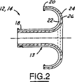
図2は、図1Aに類似した二重層ロールブーツ14のより詳細な長手方向断面図を示す。ロールブーツ14は、ブーツシール壁13によって接続された第1の端部18と第2の端部20とを有する。第1の端部18は、クランプを受けるための環状溝を含んでいる。第2の端部20は、クリンプで固定するための環状リブを含む。ブーツシール壁13は、エラストマー材料で作られた2つ又はそれ以上の層を含む。この例では、ブーツシール壁13は、外層22と内層24とを含む。外層22及び内層24は、ボンディング領域26で接している。ボンディング領域26は、各材料間の接合面又はボンディング面を表している。ボンディング領域26は、内層24及び外層22を互いに結合する接着接合面、ボンデッド接合面、粘着接合面或いは別の従順な材料とすることができる。ボンディング領域26はまた、ブーツシールの付加的特性保護及び耐久性を達成するために、例えば耐グリース性及びオゾン性の層に加えて高い強度保護を達成するために層内部において多層とすることもできる。織った又は撚ったプラスチック又はファブリック材料で、ボンディング領域26を構成することができる。
FIG. 2 shows a more detailed longitudinal cross-sectional view of a dual layer roll boot 14 similar to FIG. 1A. The roll boot 14 has a
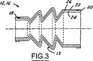
図3は、図1Bに類似した二重層折曲げ状ブーツのより詳細な長手方向断面図を示す。折曲げ状ブーツ16は、ブーツシール壁13によって接続された第1の端部18と第2の端部20とを有する。第1の端部18は、クランプ又はクリンプで固定するための環状溝又は環状リブを含む。第2の端部20は、クランプ又はクリンプで固定するための環状溝又は環状リブを含む。ブーツシール壁13は、エラストマー材料で作られた2つ又はそれ以上の層を含む。ブーツシール壁13は、外層22と内層24とを含む。外層22及び内層24は、ボンディング領域26で接している。ボンディング領域26は、各材料間の接合面又はボンディング面を表している。ボンディング領域26は、内層24及び外層22を互いに結合する接着接合面、ボンデッド接合面、粘着接合面或いは別の従順な材料とすることができる。ボンディング領域26はまた、ブーツシールの付加的特性保護及び耐久性を達成するために、例えば耐グリース性及びオゾン性の層に加えて高い強度保護を達成するために層内部において多層とすることもできる。織った又は撚ったプラスチック又はファブリック材料で、ボンディング領域26を構成することができる。別の実施形態では、ボンディング領域26は、外層22と内層24間に、かみ合った従順層を含むことができる。従順層は、異なる層22、24の材料と適合性がある織った又は撚ったプラスチック又は他のファブリック材料のものとすることができる。
FIG. 3 shows a more detailed longitudinal cross-sectional view of a double-layer folded boot similar to FIG. 1B. The foldable boot 16 has a
折曲げ状ブーツであれロールブーツであれ、ブーツシールの成形は、当業者には公知の射出成形、ブロー成形又はその他の方法によっている。以下の例に示す実施形態は、デュアル射出成形される。プロセスは、第1の材料を射出成形する段階と次に第2の材料を射出成形する段階とを含む。このプロセスは、同時に又は連続して行うことができる。それぞれ、第1の材料は内層か又は外層とし、また第2の材料は外層か又は内層とする。2つの層の材料は、射出成形プロセスの間にボンディングされかつ硬化される。内層用の材料は、水素化ニトリルゴム(HNBR)のようなグリース適合性材料の群から選択することができる。外層用の材料は、エチレンプロピレンジエンゴム(EPDM)、クロロピレンゴム(CR)又はフロロシリコンゴム(FQM)のような耐環境性又はオゾン性材料の群から選択することができる。内層又は外層材料は、あらゆる組合せのエラストマー材料から選択することができる。2つの層はさらに、内層としての強化繊維を備えたHNBRのような1つの層と外層としての繊維強化HNBRとを有するように、同一の材料群から選択することができる。さらに、ブーツシール壁性能は、ブーツシールの内層及び外層として選択したあらゆる材料の組合せで高めることができる。内層及び外層の材料は、様々な環境に対する耐性を強化しながら適合性を高めるように選択しなければならない。例えば、選択規準は、グリースを有する内部環境とオゾンを有する外部環境とに対して保護することを含むことができる。勿論、特定の選択規準は、検討中の特別のブーツシール用途に応じて変わることになる。他の選択規準は、耐摩耗性、耐化学物質性、耐可視又は不可視(UV、IR)光線性などを含むことができる。 Whether it is a fold boot or a roll boot, the boot seal is formed by injection molding, blow molding or other methods known to those skilled in the art. The embodiments shown in the examples below are dual injection molded. The process includes injection molding a first material and then injection molding a second material. This process can be performed simultaneously or sequentially. In each case, the first material is the inner layer or the outer layer, and the second material is the outer layer or the inner layer. The two layers of material are bonded and cured during the injection molding process. The material for the inner layer can be selected from the group of grease compatible materials such as hydrogenated nitrile rubber (HNBR). The material for the outer layer can be selected from the group of environmentally resistant or ozone materials such as ethylene propylene diene rubber (EPDM), chloropyrene rubber (CR) or fluorosilicone rubber (FQM). The inner or outer layer material can be selected from any combination of elastomeric materials. The two layers can further be selected from the same material group to have one layer, such as HNBR with reinforcing fibers as the inner layer, and fiber reinforced HNBR as the outer layer. Furthermore, the boot seal wall performance can be enhanced with any combination of materials selected as the inner and outer layers of the boot seal. The inner and outer layer materials must be selected to enhance compatibility while enhancing resistance to various environments. For example, the selection criteria can include protecting against an internal environment having grease and an external environment having ozone. Of course, the particular selection criteria will vary depending on the particular boot seal application under consideration. Other selection criteria may include abrasion resistance, chemical resistance, visible or invisible (UV, IR) light resistance, and the like.
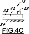
図4A、図4B及び図4Cは、本発明によるジョイント接続端部におけるブーツシール壁の様々な実施形態の部分的な長手方向断面図を示す。内層24及び外層22を有するブーツシール壁13は、図1Aに示すようにクランプ28又はクリンプ接続部を使用して、それぞれ第1の端部18又は第2の端部20においてシャフト30又はジョイント10のハウジング32に接続される。3つの断面図の各々は、内層24及び外層22の積層構成を表す。
4A, 4B and 4C show partial longitudinal cross-sectional views of various embodiments of boot seal walls at the joint connection end according to the present invention. A
図4Aは、内層24が外部環境に露出せず、外層22によって完全に覆われていることを示す。つまり、外層22は、内層24の端部領域を覆って延びる。従って、外層22は、局所的にクランプ28の領域においてのみ内層24と同じ環境を受けることになる。
FIG. 4A shows that the
図4Bは、外層22が外部環境にのみに曝され、内層24が内部環境に曝されるような材料層を示す。このケースでは、内層24の端部領域は、外層22の実質的に端部において終端するようにテーパが付いている。図4Cは、内層24の端部領域が外部環境に曝されるが、外層22は内部環境に曝されないような材料層を示す。
FIG. 4B shows a material layer in which the
内層24及び外層22の成形は、厚さを均一にすることができ或いは厚さを不均一なものとすることができる。各層はまた、異なる厚さとすることができる。本発明の実施形態では、ブーツシールは、均一な厚さのものであり、ボンディング領域においてボンディングされる2つの層22、24は、図4Aに示すように各層22、24が内部及び外部流体に最小限度曝されるようなボンディング領域26の周りでクランプ28されるか又はクリンプされることになる。
The molding of the
本発明を幾つかの実施形態に関して説明してきたが、本発明はこれらの実施形態に限定されるものではないことを理解されたい。例えば、検討中の特定の用途についての強度又は摩耗要件を満たすために、3つ又はそれ以上の層を必要としてもよい。従って、本発明は、特許請求の範囲の技術思想及び技術的範囲内に含むことができる全ての変形、改良及び均等物を保護するものである。 Although the invention has been described with respect to several embodiments, it should be understood that the invention is not limited to these embodiments. For example, three or more layers may be required to meet strength or wear requirements for the particular application under consideration. Accordingly, the present invention is intended to protect all modifications, improvements, and equivalents that can be included within the spirit and scope of the appended claims.
10 ジョイント、12 ブーツシール、13 ブーツシール壁、14 ロールブーツ、15、24 内層、17、22 外層、26 ボンディング領域、18 第1の端部、20 第2の端部、28 クリンプ部分、29 クランプ、30 シャフト、31 内側ジョイント部品、32 カバー、33 外側ジョイント部品 10 Joint, 12 Boot seal, 13 Boot seal wall, 14 Roll boot, 15, 24 Inner layer, 17, 22 Outer layer, 26 Bonding area, 18 First end, 20 Second end, 28 Crimp part, 29 Clamp , 30 Shaft, 31 Inner joint part, 32 Cover, 33 Outer joint part
Claims (16)
第2の端部と、
前記第1の端部及び第2の端部間に延び、かつ各々が異なる材料を含むグリースに対して耐性のある内層とオゾンに対して耐性のある外層とを備えるブーツシール壁と、
から成るブーツシールであって、
前記ブーツシール内層は、前記第1と第2の両端部に露出された端部領域を有し、前記外層は前記端部領域が外部環境に露出されないよう、前記内層の周囲にあり、前記内層の端部領域は前記外層の端部において終端するようにテーパが付き、そして、前記内外層はテーパ領域でクランプされていることを特徴とするブーツシール。A first end;
A second end;
A boot seal wall comprising an inner layer that extends between the first and second ends and that is resistant to grease, each containing a different material, and an outer layer that is resistant to ozone;
A boot seal comprising:
The boot seal inner layer has a first and end region which is exposed at the second end portions, said outer layer so that the end region is not exposed to the external environment, located in the periphery of the inner layer, the inner layer A boot seal characterized in that the end region is tapered to terminate at the end of the outer layer, and the inner and outer layers are clamped in the tapered region .
第2のジョイント部品に接続される第2の端部と、
前記第1の端部及び第2の端部間に延び、かつ各々が異なる材料を含グリースに対して耐性のある内層とオゾンに対して耐性のある外層とを備えるブーツシール壁と、
から成るジョイントをシールするためのブーツシールであって、
前記ブーツシール内層は、前記第1と第2の両端部に露出された端部領域を有し、前記外層は前記端部領域が外部環境に露出されないよう、前記内層の周囲にあり、前記内層の端部領域は前記外層の端部において終端するようにテーパが付き、そして、前記内外層はテーパ領域でクランプされていることを特徴とするジョイントをシールするためのブーツシール。A first end connected to the first joint component;
A second end connected to the second joint part;
A boot seal wall comprising an inner layer extending between the first end and the second end, each of which is made of a different material and resistant to grease, and an outer layer resistant to ozone;
A boot seal for sealing a joint comprising:
The boot seal inner layer has a first and end region which is exposed at the second end portions, said outer layer so that the end region is not exposed to the external environment, located in the periphery of the inner layer, the inner layer A boot seal for sealing a joint, characterized in that the end region of the taper is tapered to terminate at the end of the outer layer, and the inner and outer layers are clamped in the tapered region .
Applications Claiming Priority (3)
| Application Number | Priority Date | Filing Date | Title |
|---|---|---|---|
| US10/656,991 | 2003-09-05 | ||
| US10/656,991 US6942223B2 (en) | 2003-09-05 | 2003-09-05 | Dual layer roll boot |
| PCT/US2004/028514 WO2005026590A1 (en) | 2003-09-05 | 2004-09-02 | Dual layer roll boot |
Publications (3)
| Publication Number | Publication Date |
|---|---|
| JP2007504419A JP2007504419A (en) | 2007-03-01 |
| JP2007504419A5 JP2007504419A5 (en) | 2007-10-04 |
| JP5138931B2 true JP5138931B2 (en) | 2013-02-06 |
Family
ID=34226474
Family Applications (1)
| Application Number | Title | Priority Date | Filing Date |
|---|---|---|---|
| JP2006526172A Expired - Fee Related JP5138931B2 (en) | 2003-09-05 | 2004-09-02 | Double layer roll boots |
Country Status (5)
| Country | Link |
|---|---|
| US (1) | US6942223B2 (en) |
| JP (1) | JP5138931B2 (en) |
| CN (1) | CN100538098C (en) |
| DE (1) | DE112004001519B4 (en) |
| WO (1) | WO2005026590A1 (en) |
Families Citing this family (19)
| Publication number | Priority date | Publication date | Assignee | Title |
|---|---|---|---|---|
| US8220127B2 (en) * | 2004-03-10 | 2012-07-17 | Ashwood River Pty Ltd | Replacement of steering rack boots |
| US20050129890A1 (en) * | 2004-08-05 | 2005-06-16 | Wang Shen-Ling A. | Automotive driveline components manufactured of hydrogenated nitrile butadiene rubber material |
| EP1970586B1 (en) * | 2005-12-22 | 2011-11-30 | NTN Corporation | Joint assembly and vehicle-use bearing unit, and axle module provided with them |
| US20100044965A1 (en) * | 2006-05-01 | 2010-02-25 | Eddie York-Shin Lou | Laminated Multiple-layered split boot |
| US8136816B1 (en) * | 2006-05-01 | 2012-03-20 | Eddie York-Shin Lou | Laminated multiple-layered split boot |
| US7395582B2 (en) | 2006-07-12 | 2008-07-08 | Honda Motor Company, Ltd. | Article retention band |
| US7913705B2 (en) * | 2007-02-07 | 2011-03-29 | Tbw Industries, Inc. | Cleaning cup system for chemical mechanical planarization apparatus |
| DE102007036981A1 (en) * | 2007-08-06 | 2009-02-12 | Zumtobel Lighting Gmbh | Waterproof luminaire |
| US20090058012A1 (en) * | 2007-08-31 | 2009-03-05 | Trent Edward Walters | Seal for a rotating laser transmitter |
| US8088015B2 (en) | 2007-11-01 | 2012-01-03 | Gkn Driveline North America, Inc. | Self-repairing boot for a constant velocity joint |
| CN101910662B (en) * | 2007-11-23 | 2015-08-05 | Gkn传动系统股份有限公司 | Shaft assembly |
| US8640815B2 (en) | 2011-02-10 | 2014-02-04 | Honda Motor Company, Ltd. | Boot assembly |
| JP5313284B2 (en) | 2011-03-28 | 2013-10-09 | 豊田合成株式会社 | Boot seal for variable compression ratio engine |
| US20140221109A1 (en) * | 2011-09-21 | 2014-08-07 | Gkn Driveline North America, Inc. | External rolling diaphragm overmoulded high speed constant velocity joint boot |
| JP6121125B2 (en) * | 2012-09-28 | 2017-04-26 | ニッタ株式会社 | Joint boots |
| DE102016201046A1 (en) | 2016-01-26 | 2017-07-27 | Zf Friedrichshafen Ag | Ball joint for a vehicle, in particular for an off-road vehicle |
| JP2020512515A (en) * | 2017-03-31 | 2020-04-23 | デーナ、オータモウティヴ、システィムズ、グループ、エルエルシー | Constant velocity joint assembly |
| DE102017217633A1 (en) * | 2017-10-04 | 2019-04-04 | Volkswagen Aktiengesellschaft | Method for producing a damping element, in particular for the steering system of a motor vehicle or damping element, in particular for the steering system of a motor vehicle or steering system of a motor vehicle |
| WO2020092746A1 (en) * | 2018-10-31 | 2020-05-07 | National Oilwell DHT, L.P. | Apparatus, systems, and methods for a reinforced seal element for joints on a drilling tool |
Family Cites Families (24)
| Publication number | Priority date | Publication date | Assignee | Title |
|---|---|---|---|---|
| US1922431A (en) * | 1929-06-29 | 1933-08-15 | Inland Mfg Co | Flexible boot for universal joints |
| US3213764A (en) * | 1963-11-27 | 1965-10-26 | Bendix Corp | Damped bellows construction |
| US3381987A (en) * | 1965-06-04 | 1968-05-07 | Ford Motor Co | Double wall seal for articulated joints |
| BR8201276A (en) | 1981-03-20 | 1983-01-18 | Gates Rubber Co | CORRUGATED FLEXIBLE PROTECTOR CONJUGATED TEMPLATE TO PRODUCE PAIRS OF PROTECTORS |
| DE3506751A1 (en) * | 1984-02-29 | 1985-08-29 | John Deks Australia Pty. Ltd., Bayswater, Victoria | DEVICE FOR SEALING A PIPELINE GRID |
| JPS60227060A (en) * | 1984-04-26 | 1985-11-12 | Toyoda Gosei Co Ltd | Dustboot for equi-speed joint |
| JPS61256024A (en) | 1985-05-08 | 1986-11-13 | Toyoda Gosei Co Ltd | Boot for mechanical shaft coupling |
| JPS61266876A (en) * | 1985-05-20 | 1986-11-26 | Toyoda Gosei Co Ltd | Resin dust boot |
| EP0342061B1 (en) | 1988-05-13 | 1995-11-02 | Canon Kabushiki Kaisha | Projection exposure apparatus |
| EP0347061B1 (en) * | 1988-05-31 | 1992-07-15 | Keeper Co. Ltd | Flexible boot |
| JPH0650690Y2 (en) * | 1988-05-31 | 1994-12-21 | キーパー株式会社 | Flexible boots |
| DE4037482A1 (en) * | 1990-11-24 | 1992-05-27 | Freudenberg Carl Fa | BELLOWS FROM THERMOPLASTIC ELASTOMER |
| US5145191A (en) * | 1991-04-10 | 1992-09-08 | International Sales & Engineering, Inc. | Heat-resistant protective cover for a drive axle joint seal |
| JPH05230314A (en) * | 1992-02-18 | 1993-09-07 | Nippon Zeon Co Ltd | Rubber composition |
| CA2153009C (en) * | 1994-07-07 | 2007-05-08 | Gary D. Grabaum | Constant velocity joint boot and method of making the same |
| JPH08109966A (en) * | 1994-10-13 | 1996-04-30 | Nok Corp | Boot |
| JP3725919B2 (en) * | 1995-09-26 | 2005-12-14 | キーパー株式会社 | Resin CVJ boots |
| JPH10115326A (en) * | 1996-10-11 | 1998-05-06 | Toyota Motor Corp | Flexible boot |
| US6386551B1 (en) * | 1997-03-05 | 2002-05-14 | Trw Inc. | Plastic sleeve and method of manufacturing the same |
| US6033608A (en) * | 1998-03-11 | 2000-03-07 | Milliken & Company | Method for making foam rubber tree bark-configured articles having manmade textiles backings |
| US6083109A (en) * | 1998-03-12 | 2000-07-04 | Federal-Mogul World Wide, Inc. | Unitized seal for telescopic shaft |
| EP1101982B1 (en) * | 1998-08-04 | 2007-01-10 | Nok Corporation | Split boots and method of connecting the boots, depositing agent, and heating body |
| DE19920257A1 (en) * | 1999-05-03 | 2000-11-09 | Basf Ag | Thermoplastic elastomer composition |
| JP2003049944A (en) * | 2001-08-08 | 2003-02-21 | Nitto Kogyo Co Ltd | Boot for universal joint and universal joint with the boot mounted thereon |
-
2003
- 2003-09-05 US US10/656,991 patent/US6942223B2/en not_active Expired - Fee Related
-
2004
- 2004-09-02 WO PCT/US2004/028514 patent/WO2005026590A1/en active Application Filing
- 2004-09-02 DE DE112004001519.7T patent/DE112004001519B4/en not_active Expired - Fee Related
- 2004-09-02 CN CNB2004800255024A patent/CN100538098C/en not_active Expired - Fee Related
- 2004-09-02 JP JP2006526172A patent/JP5138931B2/en not_active Expired - Fee Related
Also Published As
| Publication number | Publication date |
|---|---|
| CN100538098C (en) | 2009-09-09 |
| DE112004001519T5 (en) | 2006-10-05 |
| DE112004001519B4 (en) | 2017-01-26 |
| US6942223B2 (en) | 2005-09-13 |
| JP2007504419A (en) | 2007-03-01 |
| US20050051973A1 (en) | 2005-03-10 |
| CN1846090A (en) | 2006-10-11 |
| WO2005026590A1 (en) | 2005-03-24 |
Similar Documents
| Publication | Publication Date | Title |
|---|---|---|
| JP5138931B2 (en) | Double layer roll boots | |
| JP2003113858A (en) | Boot for constant velocity universal joint | |
| JP2008248962A (en) | Boot for constant-velocity universal joint | |
| JP3719177B2 (en) | Resin joint boots | |
| JP2007211927A (en) | Boots for constant velocity universal joint | |
| JP5081626B2 (en) | Automotive driveline components made from silicon materials | |
| US8052536B2 (en) | Boot for universal joint | |
| JP4657897B2 (en) | Seal structure | |
| JP2008309223A (en) | Boot for tripod type constant velocity universal joint | |
| JP2008002642A (en) | Shaft coupling boot | |
| JP2009228727A (en) | Dust preventing device for joint | |
| JP2009501308A (en) | Constant velocity joint boot with integral rotating diaphragm | |
| JP2007057071A (en) | Boot for constant speed universal joint | |
| CN218440632U (en) | Oil seal structure | |
| JP2001003950A (en) | Constant velocity joint boot | |
| JP2007155003A (en) | Constant velocity universal joint boot | |
| JP2009228728A (en) | Dust preventing device for joint | |
| JP5183960B2 (en) | Constant velocity universal boots | |
| RU2281423C2 (en) | Thermoplastic protecting jacket for pivot | |
| US20080258408A1 (en) | Boot for constant-velocity universal joint and fixing structure for the same | |
| JPH11303885A (en) | Boot for universal joint | |
| JP2003207055A (en) | Joint boot | |
| CA2249916A1 (en) | Polytetrafluoroethylene and elastomer seal | |
| JP2006214575A (en) | Joint boot | |
| JP2007211928A (en) | Attaching structure of boot for constant velocity universal joint |
Legal Events
| Date | Code | Title | Description |
|---|---|---|---|
| A521 | Written amendment |
Free format text: JAPANESE INTERMEDIATE CODE: A523 Effective date: 20070807 |
|
| A621 | Written request for application examination |
Free format text: JAPANESE INTERMEDIATE CODE: A621 Effective date: 20070807 |
|
| A977 | Report on retrieval |
Free format text: JAPANESE INTERMEDIATE CODE: A971007 Effective date: 20100526 |
|
| A131 | Notification of reasons for refusal |
Free format text: JAPANESE INTERMEDIATE CODE: A131 Effective date: 20100622 |
|
| A521 | Written amendment |
Free format text: JAPANESE INTERMEDIATE CODE: A523 Effective date: 20100820 |
|
| A02 | Decision of refusal |
Free format text: JAPANESE INTERMEDIATE CODE: A02 Effective date: 20110315 |
|
| A521 | Written amendment |
Free format text: JAPANESE INTERMEDIATE CODE: A523 Effective date: 20110706 |
|
| A911 | Transfer to examiner for re-examination before appeal (zenchi) |
Free format text: JAPANESE INTERMEDIATE CODE: A911 Effective date: 20110711 |
|
| A912 | Re-examination (zenchi) completed and case transferred to appeal board |
Free format text: JAPANESE INTERMEDIATE CODE: A912 Effective date: 20110729 |
|
| A521 | Written amendment |
Free format text: JAPANESE INTERMEDIATE CODE: A523 Effective date: 20120510 |
|
| A01 | Written decision to grant a patent or to grant a registration (utility model) |
Free format text: JAPANESE INTERMEDIATE CODE: A01 |
|
| A61 | First payment of annual fees (during grant procedure) |
Free format text: JAPANESE INTERMEDIATE CODE: A61 Effective date: 20121115 |
|
| R150 | Certificate of patent or registration of utility model |
Free format text: JAPANESE INTERMEDIATE CODE: R150 |
|
| FPAY | Renewal fee payment (event date is renewal date of database) |
Free format text: PAYMENT UNTIL: 20151122 Year of fee payment: 3 |
|
| R250 | Receipt of annual fees |
Free format text: JAPANESE INTERMEDIATE CODE: R250 |
|
| R250 | Receipt of annual fees |
Free format text: JAPANESE INTERMEDIATE CODE: R250 |
|
| LAPS | Cancellation because of no payment of annual fees |