JP5138530B2 - Fault management method in storage capacity virtualization technology - Google Patents
Fault management method in storage capacity virtualization technology Download PDFInfo
- Publication number
- JP5138530B2 JP5138530B2 JP2008261391A JP2008261391A JP5138530B2 JP 5138530 B2 JP5138530 B2 JP 5138530B2 JP 2008261391 A JP2008261391 A JP 2008261391A JP 2008261391 A JP2008261391 A JP 2008261391A JP 5138530 B2 JP5138530 B2 JP 5138530B2
- Authority
- JP
- Japan
- Prior art keywords
- pool
- volume
- storage system
- virtual
- vol
- Prior art date
- Legal status (The legal status is an assumption and is not a legal conclusion. Google has not performed a legal analysis and makes no representation as to the accuracy of the status listed.)
- Expired - Fee Related
Links
Images


Classifications
-
- G—PHYSICS
- G06—COMPUTING; CALCULATING OR COUNTING
- G06F—ELECTRIC DIGITAL DATA PROCESSING
- G06F3/00—Input arrangements for transferring data to be processed into a form capable of being handled by the computer; Output arrangements for transferring data from processing unit to output unit, e.g. interface arrangements
- G06F3/06—Digital input from, or digital output to, record carriers, e.g. RAID, emulated record carriers or networked record carriers
- G06F3/0601—Interfaces specially adapted for storage systems
- G06F3/0628—Interfaces specially adapted for storage systems making use of a particular technique
- G06F3/0662—Virtualisation aspects
- G06F3/0665—Virtualisation aspects at area level, e.g. provisioning of virtual or logical volumes
-
- G—PHYSICS
- G06—COMPUTING; CALCULATING OR COUNTING
- G06F—ELECTRIC DIGITAL DATA PROCESSING
- G06F11/00—Error detection; Error correction; Monitoring
- G06F11/07—Responding to the occurrence of a fault, e.g. fault tolerance
- G06F11/16—Error detection or correction of the data by redundancy in hardware
- G06F11/20—Error detection or correction of the data by redundancy in hardware using active fault-masking, e.g. by switching out faulty elements or by switching in spare elements
- G06F11/2053—Error detection or correction of the data by redundancy in hardware using active fault-masking, e.g. by switching out faulty elements or by switching in spare elements where persistent mass storage functionality or persistent mass storage control functionality is redundant
- G06F11/2056—Error detection or correction of the data by redundancy in hardware using active fault-masking, e.g. by switching out faulty elements or by switching in spare elements where persistent mass storage functionality or persistent mass storage control functionality is redundant by mirroring
- G06F11/2069—Management of state, configuration or failover
-
- G—PHYSICS
- G06—COMPUTING; CALCULATING OR COUNTING
- G06F—ELECTRIC DIGITAL DATA PROCESSING
- G06F3/00—Input arrangements for transferring data to be processed into a form capable of being handled by the computer; Output arrangements for transferring data from processing unit to output unit, e.g. interface arrangements
- G06F3/06—Digital input from, or digital output to, record carriers, e.g. RAID, emulated record carriers or networked record carriers
- G06F3/0601—Interfaces specially adapted for storage systems
- G06F3/0602—Interfaces specially adapted for storage systems specifically adapted to achieve a particular effect
- G06F3/0608—Saving storage space on storage systems
-
- G—PHYSICS
- G06—COMPUTING; CALCULATING OR COUNTING
- G06F—ELECTRIC DIGITAL DATA PROCESSING
- G06F3/00—Input arrangements for transferring data to be processed into a form capable of being handled by the computer; Output arrangements for transferring data from processing unit to output unit, e.g. interface arrangements
- G06F3/06—Digital input from, or digital output to, record carriers, e.g. RAID, emulated record carriers or networked record carriers
- G06F3/0601—Interfaces specially adapted for storage systems
- G06F3/0602—Interfaces specially adapted for storage systems specifically adapted to achieve a particular effect
- G06F3/0614—Improving the reliability of storage systems
- G06F3/0617—Improving the reliability of storage systems in relation to availability
-
- G—PHYSICS
- G06—COMPUTING; CALCULATING OR COUNTING
- G06F—ELECTRIC DIGITAL DATA PROCESSING
- G06F3/00—Input arrangements for transferring data to be processed into a form capable of being handled by the computer; Output arrangements for transferring data from processing unit to output unit, e.g. interface arrangements
- G06F3/06—Digital input from, or digital output to, record carriers, e.g. RAID, emulated record carriers or networked record carriers
- G06F3/0601—Interfaces specially adapted for storage systems
- G06F3/0668—Interfaces specially adapted for storage systems adopting a particular infrastructure
- G06F3/067—Distributed or networked storage systems, e.g. storage area networks [SAN], network attached storage [NAS]
-
- G—PHYSICS
- G06—COMPUTING; CALCULATING OR COUNTING
- G06F—ELECTRIC DIGITAL DATA PROCESSING
- G06F11/00—Error detection; Error correction; Monitoring
- G06F11/07—Responding to the occurrence of a fault, e.g. fault tolerance
- G06F11/16—Error detection or correction of the data by redundancy in hardware
- G06F11/20—Error detection or correction of the data by redundancy in hardware using active fault-masking, e.g. by switching out faulty elements or by switching in spare elements
- G06F11/2053—Error detection or correction of the data by redundancy in hardware using active fault-masking, e.g. by switching out faulty elements or by switching in spare elements where persistent mass storage functionality or persistent mass storage control functionality is redundant
- G06F11/2056—Error detection or correction of the data by redundancy in hardware using active fault-masking, e.g. by switching out faulty elements or by switching in spare elements where persistent mass storage functionality or persistent mass storage control functionality is redundant by mirroring
- G06F11/2071—Error detection or correction of the data by redundancy in hardware using active fault-masking, e.g. by switching out faulty elements or by switching in spare elements where persistent mass storage functionality or persistent mass storage control functionality is redundant by mirroring using a plurality of controllers
- G06F11/2076—Synchronous techniques
-
- G—PHYSICS
- G06—COMPUTING; CALCULATING OR COUNTING
- G06F—ELECTRIC DIGITAL DATA PROCESSING
- G06F11/00—Error detection; Error correction; Monitoring
- G06F11/07—Responding to the occurrence of a fault, e.g. fault tolerance
- G06F11/16—Error detection or correction of the data by redundancy in hardware
- G06F11/20—Error detection or correction of the data by redundancy in hardware using active fault-masking, e.g. by switching out faulty elements or by switching in spare elements
- G06F11/2053—Error detection or correction of the data by redundancy in hardware using active fault-masking, e.g. by switching out faulty elements or by switching in spare elements where persistent mass storage functionality or persistent mass storage control functionality is redundant
- G06F11/2056—Error detection or correction of the data by redundancy in hardware using active fault-masking, e.g. by switching out faulty elements or by switching in spare elements where persistent mass storage functionality or persistent mass storage control functionality is redundant by mirroring
- G06F11/2082—Data synchronisation
-
- G—PHYSICS
- G06—COMPUTING; CALCULATING OR COUNTING
- G06F—ELECTRIC DIGITAL DATA PROCESSING
- G06F11/00—Error detection; Error correction; Monitoring
- G06F11/07—Responding to the occurrence of a fault, e.g. fault tolerance
- G06F11/16—Error detection or correction of the data by redundancy in hardware
- G06F11/20—Error detection or correction of the data by redundancy in hardware using active fault-masking, e.g. by switching out faulty elements or by switching in spare elements
- G06F11/2053—Error detection or correction of the data by redundancy in hardware using active fault-masking, e.g. by switching out faulty elements or by switching in spare elements where persistent mass storage functionality or persistent mass storage control functionality is redundant
- G06F11/2056—Error detection or correction of the data by redundancy in hardware using active fault-masking, e.g. by switching out faulty elements or by switching in spare elements where persistent mass storage functionality or persistent mass storage control functionality is redundant by mirroring
- G06F11/2087—Error detection or correction of the data by redundancy in hardware using active fault-masking, e.g. by switching out faulty elements or by switching in spare elements where persistent mass storage functionality or persistent mass storage control functionality is redundant by mirroring with a common controller
Landscapes
- Engineering & Computer Science (AREA)
- Theoretical Computer Science (AREA)
- Physics & Mathematics (AREA)
- General Engineering & Computer Science (AREA)
- General Physics & Mathematics (AREA)
- Human Computer Interaction (AREA)
- Quality & Reliability (AREA)
- Information Retrieval, Db Structures And Fs Structures Therefor (AREA)
Description
本発明は、ストレージシステム及び計算機システムの容量仮想化技術に関する。 The present invention relates to a capacity virtualization technology for a storage system and a computer system.
計算機の普及に伴って、扱うデータの規模が年々増加してきている。ストレージ装置は、大規模なデータを安全にかつ効率的に保持する装置であって、計算機と通信回線で接続され、ボリューム(データの入れ物)を提供する。ボリュームは利用状況に応じた動的な容量変更が基本的にできないため、システム構築時にボリューム容量を余裕を持って割当てる必要があり容量リソースが有効に活用されない、という課題があった。 With the spread of computers, the scale of data handled is increasing year by year. A storage device is a device that holds large-scale data safely and efficiently, and is connected to a computer through a communication line to provide a volume (data container). Since the volume cannot basically be changed dynamically according to the usage status, there is a problem that it is necessary to allocate the volume capacity with a margin when the system is constructed, and the capacity resource is not effectively used.
これに対し、容量仮想化(Thin Provisioning)技術は、ホストに対して仮想的な容量を持つボリューム(仮想VOL)を提供し、一方ストレージ側には実際に書込みがあったデータのみに容量を割当てることでボリューム容量を効率良く活用する技術である。データの書込み先には、複数のボリューム(プールボリューム:以下、「Pool VOL」と記載する。)から構成した容量境界のない大容量のプールを用いる。仮想VOLはプールから、プールはPool VOLから、さらにPool VOLは物理デバイス(アレイグループ)から提供されるため、下位の構成要素に障害があって閉塞するとそれより上位の構成要素は基本的にすべて利用不可となる。 On the other hand, capacity provisioning (Thin Provisioning) technology provides a virtual volume (virtual VOL) to the host, while the storage side allocates capacity only to the data that was actually written. This is a technology that makes efficient use of volume capacity. As a data write destination, a large-capacity pool without a capacity boundary composed of a plurality of volumes (pool volume: hereinafter referred to as “Pool VOL”) is used. Virtual VOL is provided from the pool, pool is provided from the Pool VOL, and Pool VOL is provided from the physical device (array group), so if the lower component is faulty and blocked, all the upper components are basically all It becomes unavailable.
このため、特許文献1では、容量仮想化における前記構成要素の構成を保持しておくことで、構成要素の閉塞時に関連する閉塞部位を特定し正しく閉塞する技術を示した。 For this reason, Japanese Patent Application Laid-Open No. H10-228561 has shown a technique for identifying and properly closing a blockage site related to blockage of a component by maintaining the configuration of the component in capacity virtualization.
大量のデータを扱う企業を中心に、ストレージ装置は業務継続に必須のインフラとなっており、突発的な事故や災害等さらにはコンピュータウィルスやアプリケーションエラー等によって、ボリュームやデータが破壊され利用不可となることは、業務に深刻な影響を与えかねない。このため、通常はストレージが提供するコピー制御機能を用いてデータの複製(レプリカやバックアップ)を作成する。単一ストレージ内での複製をローカルコピー、ストレージ間での複製をリモートコピーと呼ぶ。コピー制御機能では、正ボリューム(P−VOL)から副ボリューム(副VOL)にデータを同期させる。正ボリュームと副ボリュームの対をコピーペアと呼び、コピーペアはデータを常に同期させるPair(同期)状態と、データを同期しないSuspend状態を持つ。また、コピー制御機能を用いて前記コピーペアの状態をPaid状態からSuspend状態に変更すること(Split)、またその逆をすること(Resync)が可能である。正ボリュームのデータに論理障害等が発生した場合、リストア(Restore/Reverse Resync)を行うことで正ボリュームのデータを副ボリュームに保存されたデータに戻すことができる。 The storage system is an essential infrastructure for business continuity, mainly for companies that handle large amounts of data. Volumes and data are destroyed due to sudden accidents, disasters, computer viruses, application errors, etc. This can have a serious impact on operations. For this reason, a copy of data (replica or backup) is usually created using a copy control function provided by the storage. A copy within a single storage is called a local copy, and a copy between storages is called a remote copy. In the copy control function, data is synchronized from the primary volume (P-VOL) to the secondary volume (secondary VOL). A pair of a primary volume and a secondary volume is called a copy pair, and the copy pair has a Pair (synchronization) state in which data is always synchronized and a Suspend state in which data is not synchronized. Further, it is possible to change the copy pair status from the Paid status to the Suspend status using the copy control function (Split) and vice versa (Resync). When a logical failure or the like occurs in the data of the primary volume, the data of the primary volume can be restored to the data stored in the secondary volume by performing a restore (Restore / Reverse Resync).
前記容量仮想化技術において仮想ボリュームのレプリカを作成すると、コピー元の主ボリュームが持つ仮想的な容量を副ボリューム側では実容量として確保する必要あり、ストレージの記憶容量を有効に利用できない。 When a replica of a virtual volume is created by the capacity virtualization technique, it is necessary to secure the virtual capacity of the copy source main volume as the actual capacity on the secondary volume side, and the storage capacity of the storage cannot be used effectively.
このため特許文献2では、副ボリュームを仮想ボリュームとし、コピー先でも容量化仮想化機能を適用することで、実容量を使用している(実記憶領域が割り当てられている)データについてのみ、コピー元からコピーする技術を示した。
For this reason, in
ストレージ容量の効率活用という点では、ストレージ装置内に外部のストレージ装置(外部ストレージ)のボリューム(外部VOL)をマッピングすることで、ストレージ装置が提供するボリューム容量を拡張する外部接続機能(外接)がある。外接では、内部にマッピングされた外部VOLは基本的に内部のボリュームと同様元々ストレージ装置が持つリソースや機能を適用可能である。
特許文献2では、仮想VOLの複製を容量効率良く実現するため、容量仮想化技術を用いてコピー先でもプールを構成する。これにはコピー元と同じ構成のプールが必要で、プールを維持するためのキャッシュや制御プロセスのリソースを確保しなければならない。
In
また、物理デバイスあるいはPool VOLの閉塞から復旧する際、仮想VOLの切替えが必要である。仮想VOLの切替えには、障害検出から閉塞処理、さらにはホスト計算機と連動したボリューム切り替え処理が必要で、操作あるいは事前設定が煩雑であることと、迅速な復旧ができないといった課題があった。 Also, when recovering from a physical device or Pool VOL blockage, it is necessary to switch the virtual VOL. Switching between virtual VOLs requires failure detection, blockage processing, and volume switching processing in conjunction with the host computer, and there are problems such as complicated operation or pre-setting and quick recovery.
本発明では、仮想VOLの複製を別の仮想VOLとプールの構成セットで行うのではなく、プールを構成するPool VOL毎にコピーペアを形成することで行う。物理デバイスが閉塞した際、プールを構成するPool VOLを閉塞したPool VOLから副VOLに切替える。この際、Pool VOLと仮想VOLの対応付けテーブルの登録内容でPool VOLを副VOLに書換え、容量仮想化機能に適用する。 In the present invention, the virtual VOL is replicated by forming a copy pair for each Pool VOL that configures the pool, rather than by using another virtual VOL and a pool configuration set. When the physical device is blocked, the Pool VOL that configures the pool is switched from the Pooled VOL to the secondary VOL. At this time, the Pool VOL is rewritten to the secondary VOL with the registered contents of the association table of the Pool VOL and the virtual VOL, and applied to the capacity virtualization function.
本発明によれば、仮想VOLの複製を容量効率良く実現するための方式として、従来技術(特許文献2)と比較しコピー先にプールが不要なため、プールを維持するためのキャッシュや制御プロセスのリソースがいらない。また、物理デバイスあるいはPool VOLの閉塞から復旧する際、仮想VOLの切替えが不要なため、ストレージ装置内で完結した迅速な復旧が可能となる。 According to the present invention, a cache and control process for maintaining a pool is not necessary as a method for realizing virtual VOL replication in a capacity efficient manner because a pool is not required at the copy destination as compared with the prior art (Patent Document 2). I don't need the resources. In addition, when recovering from a physical device or Pool VOL blockage, it is not necessary to switch the virtual VOL, so that it is possible to quickly complete the storage device.
以下、図面を参照しながら本発明の実施の形態について詳細に説明する。尚、これにより本発明が限定されるものではない。 Hereinafter, embodiments of the present invention will be described in detail with reference to the drawings. Note that the present invention is not limited thereby.
本実施例では単一のストレージ装置内でPool VOL閉塞とそれに伴うプール閉塞が生じた際に副VOLを用いて復旧する方式について例示する。 In this embodiment, a method of recovering by using a secondary VOL when a Pool VOL blockage and a pool blockage associated therewith occur in a single storage device will be described.
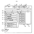
図1は本発明の一実施形態であるストレージシステム(計算機を含む)のブロック図である。ホスト計算機2201及び2202は、パーソナルコンピュータ、ワークステーション、メインフレーム等の計算機である。ホスト計算機2201及び2202では、データベースなど様々な業務や用途に応じたアプリケーションプログラムが実行される。なお、ストレージネットワーク3001を介してストレージ装置1001に接続するホスト計算機は何台であっても良い。また、ホスト計算機2201及び2202は、情報処理に係る入出力に必要なコマンド及びデータをストレージ装置1001と通信し、データの変更に関してはライト要求を行う。以降ホスト計算機2202はホスト計算機2201と等価であるため、明示することを省略する。
FIG. 1 is a block diagram of a storage system (including a computer) according to an embodiment of the present invention. Host
ストレージ装置1001は、ストレージネットワーク3001を介して送信されるコマンドやデータを受信し、所定の処理を行い、ホスト計算機2201に対して所定の応答を実行する。内部に格納されたデータは、ホスト計算機2201が認識可能な論理ボリューム(ここでは仮想VOL1401)を単位として参照や変更が可能となる。仮想VOL1401は容量仮想化機能を用いてプール1301から提供される。
The
Pool VOLはアレイグループ1101から生成された論理ボリュームであって、一つ以上のPool VOL(1201、1202、1203、…)から単一のデータ容量空間としてプール1301を構成する。また、論理ボリューム(Pool VOL1201)はストレージ装置1001が提供するコピー制御機能によって、別の論理ボリューム(副VOL 1251)に複製することができる。ここでPool VOL1201と副VOL 1251の対をコピーペア1701と呼び、コピー制御機能によって状態をPair(同期)あるいはSuspend(停止)に変更できる。これは他のPool VOLと副VOL間についても同様である。仮想VOL1401は業務に利用するため、ホスト計算機2201上で稼動するファイルシステム上にホストVOL 2401としてマウントされる。
The Pool VOL is a logical volume generated from the
管理サーバ2001は管理ネットワーク3501を通して、ストレージ装置1001の構成・保守・性能等の管理を行うための計算機である。構成設定部2101が実行され、管理者が設定した構成をストレージ装置1001に適用する。構成設定部2024自体はストレージ装置1001内部の機能として提供してもよい。また、ストレージネットワーク3001に管理サーバ2001を接続することで、管理ネットワーク3501を利用しない(例えばIn Bandのみの管理)構成とすることもできる。
The
ホスト計算機2201,2301ではホスト管理部が実行され、ホスト計算機上で稼動するアプリケーションの制御や情報取得を行うとともに、ストレージ装置1001が提供する論理ボリュームの利用状況を確認することができる。さらに、管理サーバ2001の構成設定部2111と管理ネットワークを通じて通信することで連携した処理が可能である。
In the
図2は本発明の一実施形態であるストレージ装置1001内の構成を示すブロック図である。アレイグループ1101は1つ以上の単位で物理ディスク提供ユニット1101内に格納され、電力を供給される構成とできる。ホスト計算機2201からの仮想VOL1401へのデータ参照或いは書き込み要求は、業務ポート1011或いは1012を介してコントローラ1051が受付ける。ホスト計算機2201からの前記要求に対し容量仮想化部1531は仮想ボリューム1401とプール1301とPool VOL1201の関連を元に適切なアレイグループ1101上の物理ボリュームへデータを格納(Write)あるいは読出し(Read)する。この際、内部の高速なキャッシュ1071を利用してI/Oを高速に行うことがある。
FIG. 2 is a block diagram showing a configuration within the
図3は本発明の一実施形態である管理サーバ2001の構成を示すブロック図である。管理サーバ2001は管理ネットワーク3501と管理ポート2011を介して接続される。管理サーバ2001で提供する管理機能である管理部2102はメモリ2101上にロードされ、プロセッサ2021によって実行制御される。管理操作はキーボードやマウス等のインタフェースである入力部2041によって受付け、操作結果やストレージシステムの状況をディスプレイやメールサーバ等である出力部2031から出力する。
FIG. 3 is a block diagram showing the configuration of the
構成管理テーブル(以下、「TBL」と記載する。)5101及びバックアップカタログ管理TBLは、管理サーバ2001内の二次記憶装置(ハードディスク等)からメモリ2101に適宜ロードされ、構成設定部2111から利用される。前記テーブルの格納先としては、管理サーバ2001内だけでなく、ストレージ装置1001のメモリ1501としても良い。
The configuration management table (hereinafter referred to as “TBL”) 5101 and the backup catalog management TBL are appropriately loaded from the secondary storage device (hard disk or the like) in the
図4に容量仮想化管理TBL5001の詳細を一実施例として示す。本テーブルには、各プール毎にプール1301が仮想VOL1403に提供するデータ領域(セグメント)の割当て状況を保持する。ここでセグメントはチャンクあるいはページと呼ばれることがある。プールが提供するセグメントの情報としてセグメントの識別子5021、セグメントを提供しているPool VOLの識別子5031、セグメントの提供対象となる仮想VOLの識別子5061等が格納される。
FIG. 4 shows details of the capacity
図5に構成管理TBL5101の詳細を一実施例として示す。構成管理TBL5101は、プール1301と仮想VOL1401の対応関係を保持する構成管理TBL(a)5101と、プール1301とPool VOL1201、副VOL1251の対応関係を保持する構成管理TBL(b)5201の2つのテーブルからなる。
FIG. 5 shows details of the
構成管理TBL(a)5101では、各プール毎にプール1301を利用する仮想VOL1403及び仮想VOL1403を利用するホスト計算機2202、さらに仮想VOL1403がホスト上のボリュームとしてマウントされたホストVOL5142、ホストVOL5142を利用するアプリケーション5143が定義される。ホストVOL5142とアプリケーション5143の構成情報については、ホスト計算機2201のホスト管理部2301が保持する場合、本テーブル上は不要である。なお、仮想VOL1403とホストVOL2401との関係はホストVOLが持つターゲットIDやLUN ID等から対応付け可能である。
In the configuration management TBL (a) 5101, the
図6にバックアップカタログ管理TBL5301の詳細を一実施例として示す。バックアップカタログ管理TBL5301には、プール1301単位でプールをバックアップ(Split)した時刻をSplit時刻5311として格納する。その他は構成管理TBL5101と同様、プール1301と仮想VOL1401の対応関係を保持するバックアップカタログ管理TBL(a)5301と、プール1301とPool VOL1201、副VOL1251の対応関係を保持するバックアップカタログ管理TBL(b)5401の2つのテーブルからなる。
FIG. 6 shows details of the backup
プール1301の可用性を維持するためには、プール1301に構成変更があった場合、複製する側の構成も合わせて変更する必要がある。図7に、プール1301あるいはプール1301のPool VOL1201に追加があった場合、追加されたPool VOL1201に対し副VOL1251をコピーペアとして対応付ける設定を行うフローを示す。管理ツール等から前記追加指示があると、管理サーバ2001上の構成設定部2111は設定実行処理を行う(ステップS4002)。
In order to maintain the availability of the
あらかじめプール1301が自動複製の対象か否かを構成管理TBL5101等に定義しておく。この定義に従い、前記追加指示があったプール1301が自動複製の対象である場合(ステップS4003)、登録されたPool VOL1201と同容量の副VOL1251を前記Pool VOL1201のコピーペア1701として設定する(ステップS4004)。同容量の副VOL1251がない場合、アレイグループ1101から生成する。
It is defined in advance in the
一方、容量仮想化機能として、プール1301の実容量が不足した場合、構成管理部1521がプール1301にPool VOL1201を追加する自動拡張がある。プール1301が前記自動拡張機能の対象となっている場合、プール容量が事前に設定されている閾値(実容量の使用率)を超えると、Pool VOL1201をプール1301に追加し(ステップS4105)、構成設定部2111に通知する。構成設定部2111は通知を受けると前記4003の処理に入る。この際、4003以降の処理を構成管理部1521自体が継続して実行しても良い。
On the other hand, as a capacity virtualization function, there is an automatic extension in which the
図8に、プール1301を構成しているボリューム閉塞からプール1301を復旧するためのフローを示す。アレイグループ1101あるいは論理VOL(Pool VOL1201)に障害が発生し閉塞すると障害検知部1551が検知し、閉塞箇所をプール復旧制御部1541に通知する。プール復旧制御部1541は、閉塞箇所がPool VOL1201でかつ副VOL1251とコピーペア1701を組んでいるかを構成管理TBL5101から判定する。前記組んでいる場合、Pool VOL1201を利用しているプール1301を閉塞させ、ホスト計算機2201からPool VOL1201へのWriteキャッシュを適用を停止させる。
FIG. 8 shows a flow for recovering the
次に、コピーペア1701の解除(またはSplit)をコピー制御部に対して指示する。プール1301から閉塞したPool VOL1201を外し、副VOL1251を登録するために、容量仮想化管理TBL5001のPool VOL識別子5031について前記閉塞したPool VOL1201が登録されている箇所を前記副VOL1251で置き換え、容量仮想化部1521で適用する。最後に新しくPool VOLとしてプールに登録した前記副VOL1251に対しWriteキャッシュを適用し、プール閉塞を解除する。
Next, the copy control unit is instructed to cancel (or split) the
図9にプール1301を構成しているボリューム閉塞からプール1301を復旧する際にホスト計算機2201のアプリケーションを静止化するフローを示す。障害検知部1551とプール復旧制御部1541の処理は図8と同じため、図9では一部割愛した。プール復旧制御部1541が構成管理部1521に論理VOL(1)の閉塞通知を通知すると、構成管理部1521は論理VOL(1)を使用するプール1301と仮想VOL1401を特定し(ステップS4253)、ホスト計算機2201と通信し、ホスト管理部2301に仮想VOL1401を利用するアプリケーションの静止化を指示する。該当するアプリケーションは構成管理TBL(a)5101から特定できる。ホスト管理部2301は該アプリケーションに対し静止化命令を発行し、完了後、構成管理部に対し完了イベントを発行する。
FIG. 9 shows a flow for quiescing the application of the
一方、プール復旧制御部1541はプール閉塞を解除する(ステップS4219)と、構成管理部1521に対しプール閉塞解除イベントを送信する。構成管理部1521はプール閉塞解除イベントを受信する(ステップS4256)と、ホスト管理部に静止化解除を指示し(ステップS4258)、完了イベントを受信して終了する。
On the other hand, when the pool
以下、仮想VOLが保持するデータにウィルスなどで論理障害が発生した場合、Pool VOL1201の副VOL1251を用いて復旧する方式について説明する。本方式はプールを構成する全てのPool VOL1201で副VOL1251を用いたコピーペア1701構成とすることで、論理障害時に副VOLからPool VOL1201にデータをリストア(Reverse Resync)することで、過去バックアップした時点の仮想VOLのデータをプール単位で戻すことができる。
In the following, a method for recovering data using a
図10にプール1301をバックアップするフローを示す。本フローは図1の構成において、コピーペア1701がペア状態(データが同期している)であることを前提とする。まずバックアップするプール1301あるいは仮想VOL1401が管理ツール等で指定される。構成設定部2111は、該プール1301についてプールを構成するPool VOL1201とコピーペア1701を構成管理TBL5101から特定する。仮想VOL1401が指定された場合は、あらかじめ構成管理TBL5101から対象となるプール1301を特定しておく。
FIG. 10 shows a flow for backing up the
次にプール1301を利用する仮想VOL1401について、これを利用するホスト計算機2301上のアプリケーションの静止化を実行する。静止化については図9のフロー説明を参照。静止化完了後、Writeキャッシュが残っている場合、Pool VOL1201に適用する。その後、コピー制御部に対し、上記で特定したコピーペア1701のSplit(データ同期解除)を指示する(ステップS4304)。コピーペア1701がSuspend状態になった後、容量仮想化部1531に対し容量仮想化TBL5001にバックアップ時点でのセグメントの割当て状態を追加登録するよう指示する(ステップS4305)。
Next, for the
その際、図4のSplit時刻5071を設定する。容量仮想化TBL5001の更新完了後、静止化したアプリケーションの静止化解除を実行する(詳細は図9のフロー説明を参照)。構成設定部2111はプール1301を使っている仮想VOL一覧とSplit時刻をバックアップカタログ管理TBL5301に登録し、終了する。
At that time, the
図11に、図10の処理でバックアップしたプール1301のデータを復旧(リストア)するフローを示す。まず、バックアップカタログ管理TBL5301からリストアしたい時刻のカタログが指定され、リストアが指示される。構成管理部2111はバックアップカタログ管理TBL5301から該プールを使用している仮想VOL1401と仮想VOL1401をマップしているホスト計算機2201を特定し、削除等によって現時点で存在しない仮想VOL1401があれば該プールから作成する(ステップS4403)。次にプール1301を構成するPool VOL1201及びそのコピーペア1701をバックアップカタログ管理TBL5301から特定する。該ホスト計算機2201のホスト管理部2301に対し、カタログに記載ある仮想VOL1401を使用しているアプリケーションの静止化を指示する(ステップS4405)。
FIG. 11 shows a flow for restoring (restoring) the data in the
静止化完了後、容量仮想化TBL5001において該プール1301を該時刻にSplitした管理情報を特定し、容量仮想化部1531に対し、前記管理情報の適用を指示する。前記管理情報適用後、コピー制御部1511に対し、上記で特定したコピーペア1701のリストア(Reverse Resync)の実行を指示する。最後に上記で静止化したアプリケーションの静止化解除をホスト管理部2301に対し指示し(ステップS4408)、完了後終了する。
After the completion of the staticization, the management information that splits the
本実施例では外部のストレージを接続する構成において、コントローラとなるストレージ装置内でPool VOL閉塞とそれに伴うプール閉塞が生じた際に外部VOLを用いて復旧する方式について例示する。 In this embodiment, in a configuration in which an external storage is connected, a method of recovering by using an external VOL when a Pool VOL blockage and a pool block associated therewith occur in a storage apparatus as a controller will be exemplified.
図12は本発明の一実施形態であるストレージシステム(計算機を含む)のブロック図である。ホスト計算機、ストレージ装置、管理サーバ、管理ネットワーク、ストレージネットワークについての基本的な説明は、図1と同じであるため割愛する。図1との違いは、ストレージ装置A1002の外部接続機能を用いて、ストレージ装置B1003の外部VOL1281をストレージ装置A1002内の副VOL1263として対応付けている点にある。外部接続機能を適用するためにストレージ装置A1002とストレージ装置B1003はそれぞれ外部接続ポート1016と業務ポート1013を介した通信路で物理的に接続される。外部VOL1151はストレージ装置B内のアレイグループ1151から生成される。管理サーバ2001内の構成は図3と同様のため、説明を割愛する。
FIG. 12 is a block diagram of a storage system (including a computer) according to an embodiment of the present invention. The basic description of the host computer, storage device, management server, management network, and storage network is the same as in FIG. The difference from FIG. 1 is that the
図13、図14はそれぞれ本発明の一実施形態であるストレージ装置A1002およびストレージ装置B1003内の構成を示すブロック図である。ポート、コントローラ、アレイグループ、メモリ、キャッシュ等基本的な説明は、図2と同じであるため割愛する。図13と図2との違いは、ストレージ装置Bと接続するための外部接続ポート1016があることと、外部接続機能を制御するためのプログラムとしてマイクロプログラミング部1505に外部接続制御部1561が含まれる点である。図14と図2との違いは、マイクロプログラミング部1505に構成管理部1522のみを含む点である。
FIGS. 13 and 14 are block diagrams showing configurations in the
図15に構成管理TBL(b)5202の詳細を一実施例として示す。基本的な構成について図5の構成管理TBL(b)5201と同様のため説明を割愛する。図5と図15の違いは外部ストレージ(図12の構成においてはストレージB1003)の識別子5262と外部VOL1281の識別子5272を含む点である。
FIG. 15 shows details of the configuration management TBL (b) 5202 as an example. The basic configuration is the same as that of the configuration management TBL (b) 5201 in FIG. The difference between FIG. 5 and FIG. 15 is that an
本実施例の構成においても、プール1301の可用性を維持するためには、プール1301に構成変更があった場合、複製する側の構成も合わせて変更する必要がある。図16に、プール1301あるいはプール1301のPool VOL1201に追加があった場合、追加されたPool VOL1201に対し副VOL1251をコピーペアとして対応付ける設定を行うフローを示す。図7と同じ処理について説明を割愛する。
Also in the configuration of this embodiment, in order to maintain the availability of the
本実施例では副VOL1251は外部VOL1281をマッピングする構成のため、コピーペア設定時には外部VOL1281を対応づける設定が必要となる。構成設定部2111の処理4503で該プールが自動複製の対象である場合、構成設定部2111は追加されたPool VOLと同容量の外部VOLがストレージ装置B上にありパス設定されているかを判定する。
In this embodiment, since the
Yesの場合、ストレージ装置Aの構成管理部1521に対し、外部VOL1281をストレージ装置A1002上の論理VOLとして登録し、前記論理VOLを追加されたPool VOL1201の副VOL1251としてコピーペア1701を形成するよう指示する(ステップS4506)。Noの場合、ストレージ装置B1003上の構成管理部1522に対し、追加されたPool VOL1201と同容量の外部VOLをストレージ装置B1003上に作成し、パスを設定するよう指示し、完了後前記4506の処理に進む。
In the case of Yes, the
プール1301を構成しているボリューム閉塞からプール1301を復旧するためのフローについては、実施例1の図8、図9と同様の処理となるため説明を割愛する。
The flow for restoring the
本実施例では外部のストレージを接続する構成において、コントローラとなるストレージ装置が全閉塞した場合、外部のストレージを用いて復旧(リカバリ)する方式について例示する。 In the present embodiment, in a configuration in which an external storage is connected, a method of recovering (recovering) using an external storage when a storage device serving as a controller is completely blocked will be described.
図17は本発明の一実施形態であるストレージシステム(計算機を含む)のブロック図である。本図において、ストレージ装置A1002とストレージ装置C1004の内部構造は図12におけるストレージ装置A1002とストレージ装置B1003とそれぞれ同一であるため省略する。また、ホスト計算機、管理サーバ、管理ネットワーク、ストレージネットワークについての基本的な説明についても、図12と同様割愛する。ホスト計算機2201には、ホスト管理部2301に加え、ストレージ装置内のボリュームとの経路を切替えを行うパス管理部2311と、ストレージ装置自体の障害を検知し対処を行う障害管理部2321が含まれる。
FIG. 17 is a block diagram of a storage system (including a computer) according to an embodiment of the present invention. In this figure, the internal structures of the
図18は本発明の一実施形態であるストレージ装置C1004内の構成を示すブロック図である。ポート、コントローラ、アレイグループ、メモリ、キャッシュ等基本的な説明は、図2と同じであるため割愛する。図18と図2との違いは、障害検知部1551及び構成管理TBL(b)5202を図18が含まない点である。
FIG. 18 is a block diagram showing a configuration within the storage apparatus C1004 according to an embodiment of the present invention. The basic description of ports, controllers, array groups, memories, caches, etc. is the same as in FIG. The difference between FIG. 18 and FIG. 2 is that FIG. 18 does not include the
図19は本発明の一実施形態であるストレージ装置A1002の閉塞後に、ストレージ装置C1004側にボリュームの引き継ぎを行う構成を示すブロック図である。ストレージA1002閉塞前は、図12とほぼ同様の構成となる。本実施例との違いは図19で示す容量仮想化管理TBL5001の扱いである。
FIG. 19 is a block diagram showing a configuration for taking over a volume to the
本実施例ではストレージ装置A1002閉塞後、ストレージ装置C1004側でストレージ装置A1002と同様の構成を再現する必要があるため、セグメントの対応付けと構成情報が格納された容量仮想化管理TBL5001の複製をストレージ装置C1004側に持つ必要がある(容量仮想化管理TBL5002)。この実現にはストレージ装置が持つ同期型(Synchronized)のリモートコピー機能を用いても良い。ストレージ装置A1002が閉塞するとホスト計算機2201が閉塞を検知し、ストレージ装置C1004に対し引継ぎを指示する。ストレージ装置C1004は容量仮想化管理TBL5002を使ってストレージ装置A1002と同じ構成のプール1302及び仮想VOL1402を構成する。ストレージ装置C1004の構成完了後、ホスト計算機2201はホストVOL2401の接続先パスをストレージ装置C1004に切替えることで復旧が完了する。本処理フローの詳細について以降で説明する。
In this embodiment, after the storage apparatus A1002 is blocked, it is necessary to reproduce the same configuration as the storage apparatus A1002 on the storage apparatus C1004 side. Therefore, a copy of the capacity virtualization management TBL5001 storing the segment association and configuration information is stored in the storage apparatus A1002. It is necessary to have the device C1004 side (capacity virtualization management TBL5002). To realize this, a synchronous remote copy function of the storage apparatus may be used. When the
図20にストレージ装置A1002が閉塞した際にボリュームのパス切替えを行うフローを、図21にストレージ装置C1004がストレージ装置A1002の構成を引き継ぐための設定フローを示す。図20でホスト計算機2201の障害管理部2321はストレージ装置A1002の閉塞イベントを検知し閉塞と判定した場合、ストレージ装置Cのプール復旧制御部1541に通知する(ステップS4605)。閉塞判定では、ネットワークパーティション問題を考慮し、例えばストレージ装置A1002の管理ポート1015とストレージ装置C1004の管理ポート1015両方から閉塞のイベントを受信した場合に閉塞と見なす(ステップS4603)。
FIG. 20 shows a flow for switching the volume path when the storage apparatus A1002 is blocked, and FIG. 21 shows a setting flow for the storage apparatus C1004 to take over the configuration of the storage apparatus A1002. In FIG. 20, when the
障害管理部2321はその後ストレージ装置C1004のリカバリ完了待ちを行い(ステップS4607)、プール復旧制御部1541からリカバリ完了イベントを受信すると、パス管理部2311に対し、ホストVOL2401のパスをストレージ装置C1004上の仮想VOL1402に切替えるよう指示し、完了後処理を終了する。図21でストレージ装置C1004のプール復旧制御部1541は、障害管理部2321からストレージ装置A1002の閉塞通知を受ける(ステップS4606)ことで処理を開始する。
The
まずストレージ装置A1002のPool VOL1201の副VOL1261として割当てられた外部VOL1281の有無を構成管理TBL(b)5202を用いて判定し、存在しない場合処理を終了する。存在する場合、該当する外部VOL1281のパス設定を解除し(ステップS4703)、容量仮想化管理TBL5002の書換えを行う。この書換えに先立ち必要なら容量仮想化管理TBL5002を複製するためのコピー構成を解除する。書換えはテーブルのリストの内、外部VOL1281を副VOL1261として持つPool VOL1201をPool VOL識別子5031として記載している箇所を外部VOL1281で上書きすることで行う。
First, the presence / absence of the
この際、外部VOL1281とPool VOL1201の関係は構成管理TBL(b)5202から取得する(ステップS4704)。書換え後、プール復旧制御部1541は構成管理TBL(a)5101を用いてプール1302及び仮想VOL1402構築、さらにはホスト計算機2201までのパス設定を行うよう構成管理部1521に指示する(ステップS4705)。設定完了後、容量仮想化管理TBL5002を適用するように容量仮想化部1531に指示する(ステップS4706)。適用完後、障害管理部2321に対しリカバリ完了を通知し(ステップS4707)、処理を完了する。
At this time, the relationship between the
本実施例の別形態となる実施方式について以下説明する。本実施方式は基本的な構成は図17、図19と同じであるが、ストレージ装置A1002は副VOL1261を持たず、直接ストレージ装置C1004の外部VOL1281を外部接続機能を用いてPool VOL1201にマッピングする点が異なる。
An implementation method which is another embodiment of the present embodiment will be described below. The basic configuration of this embodiment is the same as that shown in FIGS. 17 and 19, but the
ストレージ装置A1002閉塞時の処理フローも基本的には図20、図21と同じであるが、図21のステップ4702がPool VOL1201に割当てられた外部VOLの存在可否の判定であるのと、ステップ4704がPool VOL1201の登録を対応する外部VOL1281で置き換える点が異なる。以上から本実施方式においても、コントローラとなるストレージ装置の全閉塞から、外部のストレージを用いた復旧が可能である。
The processing flow when the
1000 ストレージ装置
1001 ストレージ装置
1002 ストレージ装置A
1003 ストレージ装置B
1004 ストレージ装置C
1011 業務ポート
1012 業務ポート
1013 業務ポート
1015 管理ポート
1016 外部接続ポート
1051 コントローラ
1071 キャッシュ
1081 電源
1101 アレイグループ
1102 アレイグループ
1151 アレイグループ
1201 Pool VOL
1202 Pool VOL
1203 Pool VOL
1251,1252,1253 副VOL
1261,1262,1263 副VOL
1281,1282,1283 外部VOL
1301 プール
1401 仮想VOL
1403 仮想VOL
1501 メモリ
1505 マイクロプログラミング部
1511 コピー制御部
1521 構成管理部
1522 構成管理部
1531 容量仮想化部
1541 プール復旧制御部
1551 障害検知部
1561 外部接続制御部
2000 計算機
2001 管理サーバ
2011 管理ポート
2021 プロセッサ
2031 出力部
2041 入力部
2101 メモリ
2102 管理部、
2111 構成設定部
2201 ホスト計算機
2202 ホスト計算機
2301 ホスト管理部
2401 ホストVol
3000 ネットワーク
3001 ストレージネットワーク
3501 管理ネットワーク
4000 処理シーケンス
5000 管理テーブル
5001 容量仮想化管理TBL
5011 プール
5021 セグメント
5031 Pool VOL
5041 開始LBA
5051 セグメントサイズ
5061 仮想VOL
5071 Split時刻
5101 構成管理TBL(a)
5111 プール
5121 仮想VOL
5131 容量(byte)
5141 ホスト計算機
5142 ホストVOL
5143 アプリケーション
5201 構成管理TBL(b)
5211 プール
5221 Pool VOL
5231 容量(byte)
5241 副VOL
5251 コピーペア
5301 バックアップカタログ管理TBL(a)
5311 Split時刻
5321 プール
5331 仮想VOL
5341 容量(byte)
5351 ホスト計算機
5361 ホストVOL
5371 アプリケーション
5401 バックアップカタログ管理TBL(b)
5411 Split時刻
5421 プール
5431 Pool VOL
5441 容量(byte)
5451 副VOL
5461 コピーペア
1000
1003 Storage device B
1004 Storage device C
1011
1202 Pool VOL
1203 Pool VOL
1251, 1252, 1253 Secondary VOL
1261, 1262, 1263 Secondary VOL
1281, 1282, 1283 External VOL
1301
1403 Virtual VOL
1501
2111
3000
5011
5041 Starting LBA
5051
5071
5111
5131 capacity
5141
5143
5211 Pool 5221 Pool VOL
5231 capacity
5241 Secondary VOL
5251
5311
5341 capacity
5351
5371
5411 Split Time 5421
5441 capacity
5451 Secondary VOL
5461 copy pairs
Claims (13)
前記仮想ボリュームを提供するプールと、
前記プールを構成する論理ボリュームであるプールボリュームと、
前記プールから前記仮想ボリュームが使用する記憶領域のみを前記仮想ボリュームに割り当てる容量仮想化処理部と、
前記容量仮想化処理部に利用され、前記仮想ボリュームが使用する記憶領域とプールボリュームの対応関係を保持する仮想化対応マップと、
前記プールボリュームが持つデータの複製を保持する副ボリュームと、
前記プールボリュームの障害によって前記プールが利用不可となった場合、前記仮想化対応マップについて前記利用不可となったプールボリュームを前記プールボリュームの複製を持つ副ボリュームで置換え、前記容量仮想化処理部で適用することで前記プールを利用可能とするプール復旧処理部と、
を含むことを特徴とするストレージシステム。 A virtual volume with virtual storage capacity;
A pool providing the virtual volume;
A pool volume which is a logical volume constituting the pool;
A capacity virtualization processing unit that allocates only the storage area used by the virtual volume from the pool to the virtual volume;
A virtualization correspondence map that is used in the capacity virtualization processing unit and holds a correspondence relationship between a storage area used by the virtual volume and a pool volume;
A secondary volume that holds a copy of the data of the pool volume;
When the pool becomes unavailable due to a failure of the pool volume, the unavailable pool volume in the virtualization correspondence map is replaced with a secondary volume having a copy of the pool volume, and the capacity virtualization processing unit A pool restoration processing unit that makes the pool available by applying;
A storage system comprising:
前記プールボリュームが前記プールに新たに追加された場合、前記プールボリュームと同じ容量を持つ論理ボリュームを前記プールボリュームの副ボリュームとして設定する構成設定部と、
を含むことを特徴とするストレージシステム。 The storage system according to claim 1,
A configuration setting unit that sets a logical volume having the same capacity as the pool volume as a secondary volume of the pool volume when the pool volume is newly added to the pool;
A storage system comprising:
前記プールに対し前記プールを特徴付ける特性の定義情報と、
前記定義情報に応じて副ボリュームを選択するための選択基準情報と、
を含み、
前記構成設定部は、前記プールボリュームが前記プールに新たに追加された場合、前記定義情報と前記選択基準情報から設定対象とする副ボリュームを選択すること、
を特徴とするストレージシステム。 The storage system according to claim 2, wherein
Definition information of characteristics that characterize the pool with respect to the pool;
Selection criteria information for selecting a secondary volume according to the definition information;
Including
The configuration setting unit, when the pool volume is newly added to the pool, to select a secondary volume to be set from the definition information and the selection criterion information;
A storage system characterized by
前記論理ボリュームに対し物理的に記憶領域を割り当てる物理デバイスと、
前記プールの特性を保持するプール特性情報と、
を含み、
前記構成設定部は、前記プールボリュームが前記プールに新たに追加された場合、前記プールに対応する前記プール特性情報が自動複製対象でないことを示すものについては前記プールボリュームに副ボリュームを設定しないこと、
を特徴とするストレージシステム。 The storage system according to claim 2, wherein
A physical device that physically allocates a storage area to the logical volume;
Pool property information holding the properties of the pool;
Including
When the pool volume is newly added to the pool, the configuration setting unit does not set a secondary volume for the pool volume for the pool characteristic information corresponding to the pool indicating that it is not an automatic replication target. ,
A storage system characterized by
前記ストレージシステムにネットワークを介して接続され前記仮想ボリュームを利用するホスト計算機と、
前記仮想ボリュームと前記仮想ボリュームを利用する前記ホスト計算機との対応関係を保持するホストボリューム対応情報と、
前記プールボリュームの障害から復旧した後、前記プールボリュームから提供される仮想ボリュームを利用するホスト計算機を前記ホストボリューム対応情報から特定し、前記ホスト計算機に通知を行うことを特徴とする前記プール復旧処理部と、
前記ホスト計算機内の前記仮想ボリュームが復旧した場合に、仮想ボリュームと前記仮想ボリュームを利用するプログラムの対応関係を保持する仮想ボリューム利用プログラム情報と、
前記プール復旧処理部から前記通知を受けた後、前記仮想ボリューム利用プログラム情報を参照し前記プログラムに指示を行うホスト復旧処理部と、
を含むことを特徴とするストレージシステム。 The storage system according to claim 1,
A host computer connected to the storage system via a network and using the virtual volume;
Host volume correspondence information that holds the correspondence between the virtual volume and the host computer that uses the virtual volume;
After recovering from a failure of the pool volume, the pool recovery processing is characterized in that a host computer that uses a virtual volume provided from the pool volume is identified from the host volume correspondence information and notified to the host computer. And
When the virtual volume in the host computer is restored, virtual volume use program information that holds the correspondence between the virtual volume and the program that uses the virtual volume;
After receiving the notification from the pool recovery processing unit, a host recovery processing unit that refers to the virtual volume utilization program information and instructs the program;
A storage system comprising:
前記ホスト計算機からのデータ書き込みに対し、前記仮想ボリュームに書き込む前に一時的にデータを保存しておく記憶領域であるストレージキャッシュと、
前記ストレージキャッシュから前記仮想ボリュームにデータを書き込む制御を行い、前記プール復旧制御部からプール利用不可の通知を受けるとその間前記仮想ボリュームへのデータの書き込みを停止するデータ書き込み制御部と、
を含み、
前記プール復旧制御部は、前記プールボリュームの障害によって前記プールが利用不可となった際、利用不可開始時と復旧時それぞれについてデータ書き込み制御部に対して通知を行うこと、
を特徴とするストレージシステム。 The storage system according to claim 1,
For data writing from the host computer, a storage cache that is a storage area for temporarily storing data before writing to the virtual volume;
A data write control unit that performs control to write data from the storage cache to the virtual volume, and stops writing data to the virtual volume during the period when receiving a pool unavailable notification from the pool recovery control unit;
Including
The pool recovery control unit, when the pool becomes unusable due to a failure of the pool volume, to notify the data write control unit about the unusable start time and the recovery time,
A storage system characterized by
前記プール復旧制御部は、前記プールが復旧し利用可能となった後、新たなプールボリュームに対し、同じ容量を持つ論理ボリュームを前記プールボリュームの副ボリュームとして設定すること、
を特徴とするストレージシステム。 The storage system according to claim 1,
The pool recovery control unit sets a logical volume having the same capacity as a secondary volume of the pool volume for a new pool volume after the pool is recovered and usable.
A storage system characterized by
前記ストレージシステムに接続され、前記ストレージシステムを管理する管理計算機と、
前記プールと前記プールボリューム及び、副ボリュームの対応関係を保持するプール構成情報と、
前記プールの格納データのバックアップが格納されている副ボリュームの構成を保持したプールバックアップ情報と、
前記管理計算機からのバックアップ指示を受け、前記プールのバックアップを実行する際に、前記仮想化対応マップの複製を保存し、前記プール構成情報を元に前記プールを構成する全てのプールボリュームの副ボリュームへのデータ更新を停止させ、前記プールバックアップ情報を登録するバックアップ取得処理部と、
前記管理計算機からのリストア指示を受け、前記プールを復元する際に、前記プールバックアップ情報から副ボリュームを特定し、プールボリュームを前記副ボリュームで置換えるととともに、前記仮想化対応マップを前記保存しておいたものに置き換え、前記容量仮想化処理部で適用することでプールを利用可能とするプール復旧処理部と、
を含むことを特徴とするストレージシステム。 The storage system according to claim 1,
A management computer connected to the storage system and managing the storage system;
Pool configuration information that holds the correspondence relationship between the pool, the pool volume, and the secondary volume;
Pool backup information that holds the configuration of the secondary volume that stores the backup of the pool storage data, and
When the backup of the pool is executed in response to a backup instruction from the management computer, a copy of the virtualization correspondence map is saved, and secondary volumes of all pool volumes constituting the pool based on the pool configuration information A backup acquisition processing unit for stopping the data update to and registering the pool backup information;
When restoring the pool in response to a restore instruction from the management computer, the secondary volume is specified from the pool backup information, the pool volume is replaced with the secondary volume, and the virtualization correspondence map is stored. A pool recovery processing unit that can use the pool by replacing it with the one that has been set, and applying the capacity virtualization processing unit;
A storage system comprising:
前記第1のストレージシステムは、
仮想的な記憶容量を持つ仮想ボリュームと、
前記仮想ボリュームを提供するプールと、
前記プールを構成する論理ボリュームであるプールボリュームと、
前記プールから前記仮想ボリュームが使用する記憶領域のみを前記仮想ボリュームに割り当てる容量仮想化処理部と、
前記容量仮想化処理部に利用され、前記仮想ボリュームが使用する記憶領域とプールボリュームの対応関係を保持する仮想化対応マップと、
前記第1のストレージシステムからは外部のボリュームとなる前記第2のストレージシステムの論理ボリュームを前記第1のストレージシステム上の論理ボリュームとして対応付けることで、前記第1のストレージシステムから利用可能とする外部接続処理部と、
前記外部のボリュームに対応付けられた前記第1のストレージシステムの論理ボリュームを副ボリュームとして前記プールボリュームが持つデータの複製を保持するプールボリューム複製制御部と、
前記プールボリュームの障害によって前記プールが利用不可となった場合、前記仮想化対応マップについて前記利用不可となったプールボリュームを前記プールボリュームの複製を持つ副ボリュームで置換え、前記容量仮想化処理部で適用することで前記プールを利用可能とするプール復旧処理部と、
を含むことを特徴とする計算機システム。 A first storage system and a second storage system connected to the first storage system via a network;
The first storage system is
A virtual volume with virtual storage capacity;
A pool providing the virtual volume;
A pool volume which is a logical volume constituting the pool;
A capacity virtualization processing unit that allocates only the storage area used by the virtual volume from the pool to the virtual volume;
A virtualization correspondence map that is used in the capacity virtualization processing unit and holds a correspondence relationship between a storage area used by the virtual volume and a pool volume;
An external that can be used from the first storage system by associating the logical volume of the second storage system, which is an external volume from the first storage system, with the logical volume on the first storage system. A connection processing unit;
A pool volume duplication control unit that holds a duplication of data held by the pool volume using the logical volume of the first storage system associated with the external volume as a secondary volume;
When the pool becomes unavailable due to a failure of the pool volume, the unavailable pool volume in the virtualization correspondence map is replaced with a secondary volume having a copy of the pool volume, and the capacity virtualization processing unit A pool restoration processing unit that makes the pool available by applying;
A computer system characterized by including:
前記プールボリュームが前記プールに新たに追加された場合、前記第2のストレージシステムにおいて前記プールボリュームと同じ容量を持つ外部のボリュームを検索して特定し、存在しない場合には、外部のボリュームを新たに生成する第2の構成設定部と、
前記特定されあるいは新たに生成された前記外部のボリュームを前記第1のストレージシステムに対応付け、前記プールボリュームの副ボリュームとして設定する第1の構成設定部と、
を含むことを特徴とする計算機システム。 The computer system according to claim 9, wherein
When the pool volume is newly added to the pool, an external volume having the same capacity as the pool volume is searched and specified in the second storage system. A second configuration setting unit to generate,
A first configuration setting unit that associates the specified or newly created external volume with the first storage system and sets the secondary volume as a secondary volume of the pool volume;
A computer system characterized by including:
前記第2の構成設定部は、前記外部のボリュームを前記第1のストレージシステムに対応付ける際に、前記第2のストレージシステムが持つポート識別子と前記第1のストレージシステムが持つ外部接続用のポート識別子に対しパスを設定すること、を特徴とする計算機システム。 The computer system according to claim 10,
When the second configuration setting unit associates the external volume with the first storage system, the port identifier possessed by the second storage system and the port identifier for external connection possessed by the first storage system A computer system characterized by setting a path for
前記第1の構成設定部は、前記プールの使用可能な残り容量が既定の閾値を超過した場合、前記プールに追加可能なプールボリュームを検索して特定し、存在しない場合には新たに生成した上で、前記プールに追加登録すること、を特徴とする計算機システム。 The computer system according to claim 10,
The first configuration setting unit searches for and specifies a pool volume that can be added to the pool when the available remaining capacity of the pool exceeds a predetermined threshold, and newly generates a pool volume that does not exist. A computer system characterized by additionally registering in the pool.
前記第1のストレージシステムは、
仮想的な記憶容量を持つ仮想ボリュームと、
前記仮想ボリュームを提供するプールと、
前記プールを構成する論理ボリュームであるプールボリュームと、
前記プールから前記仮想ボリュームが使用する記憶領域のみを前記仮想ボリュームに割り当てる容量仮想化処理部と、
前記容量仮想化処理部に利用され、前記仮想ボリュームが使用する記憶領域とプールボリュームの対応関係を保持する仮想化対応マップと、
前記第1のストレージシステムからは外部のボリュームとなる前記第2のストレージシステムの論理ボリュームを前記第1のストレージシステム上の論理ボリュームとして対応付けることで、前記第1のストレージシステムから利用可能とする外部接続処理部と、
前記外部のボリュームに対応付けられた前記第1のストレージシステムの論理ボリュームを副ボリュームとして前記プールボリュームが持つデータの複製を保持するプールボリューム複製制御部とを含み、
前記仮想化対応マップは、前記第1のストレージシステムと前記第2のストレージシステムの遠隔コピー制御部によって前記第1のストレージシステムから前記第2のストレージシステムに複製され、
前記第2のストレージステムは、前記第1のストレージシステムが障害によって利用不可となった場合、前記外部のボリュームを前記プールボリュームとして前記複製された仮想化対応マップを用い、前記第2のストレージシステム上に第1のストレージシステムと同じ構成のプール及び仮想ボリュームを作成し、前記ホスト計算機に通知するプール復旧処理部とを含み、
前記ホスト計算機は、前記プール復旧処理部からの通知を受け、前記第1のストレージシステム上の仮想ボリュームとの接続関係を前記第2のストレージシステム上の仮想ボリュームに切替えるパス切り替え設定部と、
を含むことを特徴とする計算機システム。
A host computer, a first storage system connected to the host computer via a network, and a second storage system connected to the host computer and the first storage system via a network,
The first storage system is
A virtual volume with virtual storage capacity;
A pool providing the virtual volume;
A pool volume which is a logical volume constituting the pool;
A capacity virtualization processing unit that allocates only the storage area used by the virtual volume from the pool to the virtual volume;
A virtualization correspondence map that is used in the capacity virtualization processing unit and holds a correspondence relationship between a storage area used by the virtual volume and a pool volume;
An external that can be used from the first storage system by associating the logical volume of the second storage system, which is an external volume from the first storage system, with the logical volume on the first storage system. A connection processing unit;
A pool volume duplication control unit that holds a duplication of data held by the pool volume using the logical volume of the first storage system associated with the external volume as a secondary volume,
The virtualization correspondence map is replicated from the first storage system to the second storage system by the remote copy control unit of the first storage system and the second storage system,
When the first storage system becomes unavailable due to a failure, the second storage system uses the replicated virtualization correspondence map with the external volume as the pool volume, and the second storage system A pool recovery unit that creates a pool and a virtual volume having the same configuration as the first storage system and notifies the host computer;
The host computer receives a notification from the pool recovery processing unit, and a path switching setting unit that switches the connection relationship with the virtual volume on the first storage system to the virtual volume on the second storage system;
A computer system characterized by including:
Priority Applications (2)
| Application Number | Priority Date | Filing Date | Title |
|---|---|---|---|
| JP2008261391A JP5138530B2 (en) | 2008-10-08 | 2008-10-08 | Fault management method in storage capacity virtualization technology |
| US12/339,309 US8140790B2 (en) | 2008-10-08 | 2008-12-19 | Failure management method in thin provisioning technology for storage |
Applications Claiming Priority (1)
| Application Number | Priority Date | Filing Date | Title |
|---|---|---|---|
| JP2008261391A JP5138530B2 (en) | 2008-10-08 | 2008-10-08 | Fault management method in storage capacity virtualization technology |
Publications (2)
| Publication Number | Publication Date |
|---|---|
| JP2010092259A JP2010092259A (en) | 2010-04-22 |
| JP5138530B2 true JP5138530B2 (en) | 2013-02-06 |
Family
ID=42076715
Family Applications (1)
| Application Number | Title | Priority Date | Filing Date |
|---|---|---|---|
| JP2008261391A Expired - Fee Related JP5138530B2 (en) | 2008-10-08 | 2008-10-08 | Fault management method in storage capacity virtualization technology |
Country Status (2)
| Country | Link |
|---|---|
| US (1) | US8140790B2 (en) |
| JP (1) | JP5138530B2 (en) |
Families Citing this family (20)
| Publication number | Priority date | Publication date | Assignee | Title |
|---|---|---|---|---|
| JP2008146574A (en) * | 2006-12-13 | 2008-06-26 | Hitachi Ltd | Storage controller and storage control method |
| US8397046B2 (en) * | 2009-03-26 | 2013-03-12 | Hitachi, Ltd. | Method and apparatus for deploying virtual hard disk to storage system |
| US8504797B2 (en) * | 2009-06-02 | 2013-08-06 | Hitachi, Ltd. | Method and apparatus for managing thin provisioning volume by using file storage system |
| US9953035B1 (en) * | 2009-10-30 | 2018-04-24 | Veritas Technologies Llc | Systems and methods for efficiently backing up data in thin-provisioned environments |
| WO2011135636A1 (en) * | 2010-04-30 | 2011-11-03 | 株式会社日立製作所 | Computer system and method for controlling same |
| JP5470594B2 (en) * | 2010-09-16 | 2014-04-16 | 株式会社日立製作所 | Computer system and storage volume management method |
| CN102063383B (en) * | 2010-12-22 | 2013-01-23 | 深圳市创新科信息技术有限公司 | Method for recording mapping relation between logical extents (LE) and physical extents (PE) |
| US8706859B2 (en) * | 2011-03-29 | 2014-04-22 | Hitachi, Ltd. | Method and apparatus of data center file system |
| JP5704331B2 (en) * | 2011-03-31 | 2015-04-22 | 日本電気株式会社 | Backup management device, backup method, and program |
| US8788877B2 (en) * | 2011-08-03 | 2014-07-22 | International Business Machines Corporation | Acquiring a storage system into copy services management software |
| US9519531B2 (en) * | 2012-11-27 | 2016-12-13 | Samsung Electronics Co., Ltd. | Memory devices and memory systems having the same |
| US9146853B2 (en) | 2013-03-28 | 2015-09-29 | Microsoft Technology Licensing, Llc | Managing capacity of a thinly provisioned storage system |
| WO2014155673A1 (en) * | 2013-03-29 | 2014-10-02 | 株式会社日立製作所 | Test environment management device and test environment building method |
| US9256629B1 (en) * | 2013-06-28 | 2016-02-09 | Emc Corporation | File system snapshots over thinly provisioned volume file in mapped mode |
| US9256614B1 (en) * | 2013-06-28 | 2016-02-09 | Emc Corporation | File system snapshots over fully provisioned volume file in direct mode |
| CN105094685B (en) | 2014-04-29 | 2018-02-06 | 国际商业机器公司 | The method and apparatus for carrying out storing control |
| US9785575B2 (en) | 2014-12-30 | 2017-10-10 | International Business Machines Corporation | Optimizing thin provisioning in a data storage system through selective use of multiple grain sizes |
| JP6668733B2 (en) | 2015-12-15 | 2020-03-18 | 富士通株式会社 | Control device, management device, storage system, control program, management program, control method, and management method |
| CN108108120B (en) * | 2016-11-25 | 2021-03-09 | 上海川源信息科技有限公司 | Data storage system and data storage method thereof |
| JP7337872B2 (en) * | 2021-03-30 | 2023-09-04 | 株式会社日立製作所 | Composite storage system and its control method |
Family Cites Families (14)
| Publication number | Priority date | Publication date | Assignee | Title |
|---|---|---|---|---|
| US5673382A (en) * | 1996-05-30 | 1997-09-30 | International Business Machines Corporation | Automated management of off-site storage volumes for disaster recovery |
| US6442663B1 (en) * | 1998-06-19 | 2002-08-27 | Board Of Supervisors Of Louisiana University And Agricultural And Mechanical College | Data collection and restoration for homogeneous or heterogeneous process migration |
| US6823442B1 (en) * | 2003-05-12 | 2004-11-23 | 3Pardata, Inc. | Method of managing virtual volumes in a utility storage server system |
| JP2006127028A (en) * | 2004-10-27 | 2006-05-18 | Hitachi Ltd | Memory system and storage controller |
| JP4699808B2 (en) * | 2005-06-02 | 2011-06-15 | 株式会社日立製作所 | Storage system and configuration change method |
| JP4945118B2 (en) * | 2005-11-14 | 2012-06-06 | 株式会社日立製作所 | Computer system that efficiently uses storage capacity |
| JP2007286806A (en) * | 2006-04-14 | 2007-11-01 | Hitachi Ltd | Storage system and data storage method |
| JP5057366B2 (en) * | 2006-10-30 | 2012-10-24 | 株式会社日立製作所 | Information system and information system data transfer method |
| JP2008181416A (en) * | 2007-01-25 | 2008-08-07 | Hitachi Ltd | Storage system and data management method |
| US7631155B1 (en) * | 2007-06-30 | 2009-12-08 | Emc Corporation | Thin provisioning of a file system and an iSCSI LUN through a common mechanism |
| JP2009093316A (en) * | 2007-10-05 | 2009-04-30 | Hitachi Ltd | Storage system and virtualization method |
| JP4961319B2 (en) * | 2007-10-11 | 2012-06-27 | 株式会社日立製作所 | A storage system that dynamically allocates real areas to virtual areas in virtual volumes |
| US20100011368A1 (en) * | 2008-07-09 | 2010-01-14 | Hiroshi Arakawa | Methods, systems and programs for partitioned storage resources and services in dynamically reorganized storage platforms |
| US8347059B2 (en) * | 2008-08-15 | 2013-01-01 | International Business Machines Corporation | Management of recycling bin for thinly-provisioned logical volumes |
-
2008
- 2008-10-08 JP JP2008261391A patent/JP5138530B2/en not_active Expired - Fee Related
- 2008-12-19 US US12/339,309 patent/US8140790B2/en not_active Expired - Fee Related
Also Published As
| Publication number | Publication date |
|---|---|
| JP2010092259A (en) | 2010-04-22 |
| US8140790B2 (en) | 2012-03-20 |
| US20100088485A1 (en) | 2010-04-08 |
Similar Documents
| Publication | Publication Date | Title |
|---|---|---|
| JP5138530B2 (en) | Fault management method in storage capacity virtualization technology | |
| US9460028B1 (en) | Non-disruptive and minimally disruptive data migration in active-active clusters | |
| US9400611B1 (en) | Data migration in cluster environment using host copy and changed block tracking | |
| US9122410B2 (en) | Storage system comprising function for changing data storage mode using logical volume pair | |
| US8892840B2 (en) | Computer system and data migration method | |
| US7558916B2 (en) | Storage system, data processing method and storage apparatus | |
| US8204858B2 (en) | Snapshot reset method and apparatus | |
| US9927980B1 (en) | Accessing point in time versions of a logical device in connection with I/O operations | |
| EP1837767B1 (en) | Storage system and data management method | |
| US8627028B2 (en) | Method of constructing replication environment and storage system | |
| US20060047926A1 (en) | Managing multiple snapshot copies of data | |
| US8719523B2 (en) | Maintaining multiple target copies | |
| JP2004252686A (en) | Information processing system | |
| US20110061049A1 (en) | Storage system, and remote copy control method therefor | |
| JP2007226347A (en) | Computer system, management device for computer system, and data recovery management method | |
| US20120260051A1 (en) | Computer system, management system and data management method | |
| US20180267713A1 (en) | Method and apparatus for defining storage infrastructure | |
| US9063892B1 (en) | Managing restore operations using data less writes | |
| US10698627B2 (en) | Storage system and storage control method | |
| JP6227771B2 (en) | System and method for managing logical volumes | |
| JP7142052B2 (en) | How to protect your data in the hybrid cloud | |
| JP2021033782A (en) | Remote copy system | |
| US20090094426A1 (en) | Storage system | |
| JP2007179552A (en) | Information processing system |
Legal Events
| Date | Code | Title | Description |
|---|---|---|---|
| A621 | Written request for application examination |
Free format text: JAPANESE INTERMEDIATE CODE: A621 Effective date: 20101105 |
|
| A977 | Report on retrieval |
Free format text: JAPANESE INTERMEDIATE CODE: A971007 Effective date: 20120510 |
|
| A131 | Notification of reasons for refusal |
Free format text: JAPANESE INTERMEDIATE CODE: A131 Effective date: 20120626 |
|
| A521 | Written amendment |
Free format text: JAPANESE INTERMEDIATE CODE: A523 Effective date: 20120808 |
|
| A131 | Notification of reasons for refusal |
Free format text: JAPANESE INTERMEDIATE CODE: A131 Effective date: 20120911 |
|
| A521 | Written amendment |
Free format text: JAPANESE INTERMEDIATE CODE: A523 Effective date: 20121026 |
|
| TRDD | Decision of grant or rejection written | ||
| A01 | Written decision to grant a patent or to grant a registration (utility model) |
Free format text: JAPANESE INTERMEDIATE CODE: A01 Effective date: 20121113 |
|
| A01 | Written decision to grant a patent or to grant a registration (utility model) |
Free format text: JAPANESE INTERMEDIATE CODE: A01 |
|
| A61 | First payment of annual fees (during grant procedure) |
Free format text: JAPANESE INTERMEDIATE CODE: A61 Effective date: 20121114 |
|
| R150 | Certificate of patent or registration of utility model |
Free format text: JAPANESE INTERMEDIATE CODE: R150 |
|
| FPAY | Renewal fee payment (event date is renewal date of database) |
Free format text: PAYMENT UNTIL: 20151122 Year of fee payment: 3 |
|
| LAPS | Cancellation because of no payment of annual fees |