JP5138303B2 - Method for adjusting elution of therapeutic agent - Google Patents
Method for adjusting elution of therapeutic agent Download PDFInfo
- Publication number
- JP5138303B2 JP5138303B2 JP2007193386A JP2007193386A JP5138303B2 JP 5138303 B2 JP5138303 B2 JP 5138303B2 JP 2007193386 A JP2007193386 A JP 2007193386A JP 2007193386 A JP2007193386 A JP 2007193386A JP 5138303 B2 JP5138303 B2 JP 5138303B2
- Authority
- JP
- Japan
- Prior art keywords
- rapamycin
- stent
- coating
- drug
- drugs
- Prior art date
- Legal status (The legal status is an assumption and is not a legal conclusion. Google has not performed a legal analysis and makes no representation as to the accuracy of the status listed.)
- Active
Links
Images


Classifications
-
- A—HUMAN NECESSITIES
- A61—MEDICAL OR VETERINARY SCIENCE; HYGIENE
- A61L—METHODS OR APPARATUS FOR STERILISING MATERIALS OR OBJECTS IN GENERAL; DISINFECTION, STERILISATION OR DEODORISATION OF AIR; CHEMICAL ASPECTS OF BANDAGES, DRESSINGS, ABSORBENT PADS OR SURGICAL ARTICLES; MATERIALS FOR BANDAGES, DRESSINGS, ABSORBENT PADS OR SURGICAL ARTICLES
- A61L31/00—Materials for other surgical articles, e.g. stents, stent-grafts, shunts, surgical drapes, guide wires, materials for adhesion prevention, occluding devices, surgical gloves, tissue fixation devices
- A61L31/08—Materials for coatings
- A61L31/10—Macromolecular materials
-
- A—HUMAN NECESSITIES
- A61—MEDICAL OR VETERINARY SCIENCE; HYGIENE
- A61L—METHODS OR APPARATUS FOR STERILISING MATERIALS OR OBJECTS IN GENERAL; DISINFECTION, STERILISATION OR DEODORISATION OF AIR; CHEMICAL ASPECTS OF BANDAGES, DRESSINGS, ABSORBENT PADS OR SURGICAL ARTICLES; MATERIALS FOR BANDAGES, DRESSINGS, ABSORBENT PADS OR SURGICAL ARTICLES
- A61L31/00—Materials for other surgical articles, e.g. stents, stent-grafts, shunts, surgical drapes, guide wires, materials for adhesion prevention, occluding devices, surgical gloves, tissue fixation devices
- A61L31/14—Materials characterised by their function or physical properties, e.g. injectable or lubricating compositions, shape-memory materials, surface modified materials
- A61L31/16—Biologically active materials, e.g. therapeutic substances
-
- A—HUMAN NECESSITIES
- A61—MEDICAL OR VETERINARY SCIENCE; HYGIENE
- A61F—FILTERS IMPLANTABLE INTO BLOOD VESSELS; PROSTHESES; DEVICES PROVIDING PATENCY TO, OR PREVENTING COLLAPSING OF, TUBULAR STRUCTURES OF THE BODY, e.g. STENTS; ORTHOPAEDIC, NURSING OR CONTRACEPTIVE DEVICES; FOMENTATION; TREATMENT OR PROTECTION OF EYES OR EARS; BANDAGES, DRESSINGS OR ABSORBENT PADS; FIRST-AID KITS
- A61F2/00—Filters implantable into blood vessels; Prostheses, i.e. artificial substitutes or replacements for parts of the body; Appliances for connecting them with the body; Devices providing patency to, or preventing collapsing of, tubular structures of the body, e.g. stents
- A61F2/02—Prostheses implantable into the body
- A61F2/04—Hollow or tubular parts of organs, e.g. bladders, tracheae, bronchi or bile ducts
- A61F2/06—Blood vessels
- A61F2/07—Stent-grafts
-
- A—HUMAN NECESSITIES
- A61—MEDICAL OR VETERINARY SCIENCE; HYGIENE
- A61F—FILTERS IMPLANTABLE INTO BLOOD VESSELS; PROSTHESES; DEVICES PROVIDING PATENCY TO, OR PREVENTING COLLAPSING OF, TUBULAR STRUCTURES OF THE BODY, e.g. STENTS; ORTHOPAEDIC, NURSING OR CONTRACEPTIVE DEVICES; FOMENTATION; TREATMENT OR PROTECTION OF EYES OR EARS; BANDAGES, DRESSINGS OR ABSORBENT PADS; FIRST-AID KITS
- A61F2/00—Filters implantable into blood vessels; Prostheses, i.e. artificial substitutes or replacements for parts of the body; Appliances for connecting them with the body; Devices providing patency to, or preventing collapsing of, tubular structures of the body, e.g. stents
- A61F2/82—Devices providing patency to, or preventing collapsing of, tubular structures of the body, e.g. stents
- A61F2/86—Stents in a form characterised by the wire-like elements; Stents in the form characterised by a net-like or mesh-like structure
- A61F2/90—Stents in a form characterised by the wire-like elements; Stents in the form characterised by a net-like or mesh-like structure characterised by a net-like or mesh-like structure
- A61F2/91—Stents in a form characterised by the wire-like elements; Stents in the form characterised by a net-like or mesh-like structure characterised by a net-like or mesh-like structure made from perforated sheet material or tubes, e.g. perforated by laser cuts or etched holes
-
- A—HUMAN NECESSITIES
- A61—MEDICAL OR VETERINARY SCIENCE; HYGIENE
- A61F—FILTERS IMPLANTABLE INTO BLOOD VESSELS; PROSTHESES; DEVICES PROVIDING PATENCY TO, OR PREVENTING COLLAPSING OF, TUBULAR STRUCTURES OF THE BODY, e.g. STENTS; ORTHOPAEDIC, NURSING OR CONTRACEPTIVE DEVICES; FOMENTATION; TREATMENT OR PROTECTION OF EYES OR EARS; BANDAGES, DRESSINGS OR ABSORBENT PADS; FIRST-AID KITS
- A61F2/00—Filters implantable into blood vessels; Prostheses, i.e. artificial substitutes or replacements for parts of the body; Appliances for connecting them with the body; Devices providing patency to, or preventing collapsing of, tubular structures of the body, e.g. stents
- A61F2/95—Instruments specially adapted for placement or removal of stents or stent-grafts
- A61F2/954—Instruments specially adapted for placement or removal of stents or stent-grafts for placing stents or stent-grafts in a bifurcation
-
- A—HUMAN NECESSITIES
- A61—MEDICAL OR VETERINARY SCIENCE; HYGIENE
- A61F—FILTERS IMPLANTABLE INTO BLOOD VESSELS; PROSTHESES; DEVICES PROVIDING PATENCY TO, OR PREVENTING COLLAPSING OF, TUBULAR STRUCTURES OF THE BODY, e.g. STENTS; ORTHOPAEDIC, NURSING OR CONTRACEPTIVE DEVICES; FOMENTATION; TREATMENT OR PROTECTION OF EYES OR EARS; BANDAGES, DRESSINGS OR ABSORBENT PADS; FIRST-AID KITS
- A61F2/00—Filters implantable into blood vessels; Prostheses, i.e. artificial substitutes or replacements for parts of the body; Appliances for connecting them with the body; Devices providing patency to, or preventing collapsing of, tubular structures of the body, e.g. stents
- A61F2/02—Prostheses implantable into the body
- A61F2/04—Hollow or tubular parts of organs, e.g. bladders, tracheae, bronchi or bile ducts
- A61F2/06—Blood vessels
- A61F2002/065—Y-shaped blood vessels
-
- A—HUMAN NECESSITIES
- A61—MEDICAL OR VETERINARY SCIENCE; HYGIENE
- A61F—FILTERS IMPLANTABLE INTO BLOOD VESSELS; PROSTHESES; DEVICES PROVIDING PATENCY TO, OR PREVENTING COLLAPSING OF, TUBULAR STRUCTURES OF THE BODY, e.g. STENTS; ORTHOPAEDIC, NURSING OR CONTRACEPTIVE DEVICES; FOMENTATION; TREATMENT OR PROTECTION OF EYES OR EARS; BANDAGES, DRESSINGS OR ABSORBENT PADS; FIRST-AID KITS
- A61F2/00—Filters implantable into blood vessels; Prostheses, i.e. artificial substitutes or replacements for parts of the body; Appliances for connecting them with the body; Devices providing patency to, or preventing collapsing of, tubular structures of the body, e.g. stents
- A61F2/02—Prostheses implantable into the body
- A61F2/04—Hollow or tubular parts of organs, e.g. bladders, tracheae, bronchi or bile ducts
- A61F2/06—Blood vessels
- A61F2/07—Stent-grafts
- A61F2002/075—Stent-grafts the stent being loosely attached to the graft material, e.g. by stitching
-
- A—HUMAN NECESSITIES
- A61—MEDICAL OR VETERINARY SCIENCE; HYGIENE
- A61L—METHODS OR APPARATUS FOR STERILISING MATERIALS OR OBJECTS IN GENERAL; DISINFECTION, STERILISATION OR DEODORISATION OF AIR; CHEMICAL ASPECTS OF BANDAGES, DRESSINGS, ABSORBENT PADS OR SURGICAL ARTICLES; MATERIALS FOR BANDAGES, DRESSINGS, ABSORBENT PADS OR SURGICAL ARTICLES
- A61L2300/00—Biologically active materials used in bandages, wound dressings, absorbent pads or medical devices
- A61L2300/40—Biologically active materials used in bandages, wound dressings, absorbent pads or medical devices characterised by a specific therapeutic activity or mode of action
- A61L2300/416—Anti-neoplastic or anti-proliferative or anti-restenosis or anti-angiogenic agents, e.g. paclitaxel, sirolimus
-
- A—HUMAN NECESSITIES
- A61—MEDICAL OR VETERINARY SCIENCE; HYGIENE
- A61L—METHODS OR APPARATUS FOR STERILISING MATERIALS OR OBJECTS IN GENERAL; DISINFECTION, STERILISATION OR DEODORISATION OF AIR; CHEMICAL ASPECTS OF BANDAGES, DRESSINGS, ABSORBENT PADS OR SURGICAL ARTICLES; MATERIALS FOR BANDAGES, DRESSINGS, ABSORBENT PADS OR SURGICAL ARTICLES
- A61L2300/00—Biologically active materials used in bandages, wound dressings, absorbent pads or medical devices
- A61L2300/60—Biologically active materials used in bandages, wound dressings, absorbent pads or medical devices characterised by a special physical form
- A61L2300/606—Coatings
Abstract
Description
〔発明の背景〕
〔発明の分野〕
本発明は、脈管の疾患の予防および治療のための、薬物/薬物の組み合わせ物の局所的投与に関連しており、特に、傷害により引き起こされる脈管の疾患の予防および治療のための、薬物/薬物の組み合わせ物の局所送達のための内腔内医療装置と、当該内腔内医療装置において薬物/薬物の組み合わせ物を保持すると共に、その医療装置に対する損傷を予防するための方法および装置、に関連している。また、本発明は、疾患を治療して予防し、生体への医療装置の導入に対する生物学的な生体反応を最小限にするか実質的に無くすために、薬物、薬剤および/または配合物(compounds)が固定されている、ステント、グラフト、吻合装置、脈管周囲ラップ、縫合糸、およびステープル、を含む医療装置、にも関連している。加えて、上記の薬物、薬剤および/または配合物は、治癒および内皮化(endothelialization)を助長するために、利用できる。また、本発明は、植え込み可能な医療装置からの、薬物、薬剤および/または配合物の溶出速度を調整するための被膜、にも関連している。また、本発明は、溶出の調整および治療剤の安定性を増すために、医療装置を被覆するための方法、にも関連している。また、本発明は、脈管の疾患を治療するための薬物ならびにそれらの薬物の液体調合物の、限局的送達(regional delivery)のための、薬物および薬物送達システム、にも関連している。また、本発明は、不安定プラークおよびその他の脈管の疾患を治療するために、薬物、薬剤および/または配合物が固定されている医療装置、にも関連している。
BACKGROUND OF THE INVENTION
(Field of the Invention)
The present invention relates to the local administration of a drug / drug combination for the prevention and treatment of vascular diseases, in particular for the prevention and treatment of vascular diseases caused by injury. Intraluminal medical device for local delivery of a drug / drug combination and method and apparatus for holding a drug / drug combination in the intraluminal medical device and preventing damage to the medical device , Is related to. The present invention also provides for the use of drugs, agents and / or formulations (in order to treat and prevent diseases and to minimize or substantially eliminate biological biological reactions to the introduction of medical devices into the body). It also relates to medical devices, including stents, grafts, anastomotic devices, perivascular wraps, sutures, and staples, to which compounds are fixed. In addition, the drugs, agents and / or formulations described above can be utilized to facilitate healing and endothelialization. The present invention also relates to a coating for adjusting the dissolution rate of drugs, agents and / or formulations from an implantable medical device. The present invention also relates to a method for coating a medical device to adjust dissolution and increase the stability of a therapeutic agent. The invention also relates to drugs and drug delivery systems for regional delivery of drugs for treating vascular diseases and liquid formulations of those drugs. The invention also relates to medical devices to which drugs, agents and / or formulations are fixed to treat vulnerable plaque and other vascular diseases.
〔関連技術の論述〕
多くの個人は心臓およびその他の主要な器官において多くある種々の血管の進行性の閉塞により生じる循環系の疾患に罹患している。これらの個人における血管のさらに深刻な閉塞は多くの場合に高血圧、虚血性の傷害、発作、または心筋梗塞を引き起こす。冠動脈の血流を制限または閉塞するアテローム硬化症の病巣は虚血性心疾患の主因である。経皮的冠動脈形成術は動脈の中を通る血流を増加することを目的としている医療処置である。この経皮的冠動脈形成術は冠動脈血管狭窄のための主要な治療である。この処置の使用の増加は冠動脈バイパス術に比べた場合のその比較的に高い成功率およびその最小限の侵襲性を起因としていると考えられる。この経皮的冠動脈形成術に付随する制限は、その処置の直後に生じる可能性のある血管の急な閉鎖、およびその処置に続いて徐々に生じる再狭窄である。加えて、この再狭窄は伏在静脈のバイパス移植術(bypass grafting)を受けている患者における慢性的な問題である。上記のような急性の閉塞のメカニズムは幾つかの要因を含むと考えられ、結果的に動脈の閉塞を伴う脈管の反跳および/または新しく開口した血管の損傷部分の長さに沿う血小板およびフィブリンの堆積により生じる可能性がある。
[Description of related technology]
Many individuals suffer from circulatory diseases caused by progressive blockage of various blood vessels, many of which are in the heart and other major organs. More severe occlusion of blood vessels in these individuals often results in hypertension, ischemic injury, stroke, or myocardial infarction. Atherosclerotic lesions that restrict or occlude coronary blood flow are a major cause of ischemic heart disease. Percutaneous coronary angioplasty is a medical procedure aimed at increasing blood flow through an artery. This percutaneous coronary angioplasty is the main treatment for coronary artery stenosis. The increased use of this procedure may be attributed to its relatively high success rate and its minimal invasiveness when compared to coronary artery bypass grafting. The limitations associated with this percutaneous coronary angioplasty are the sudden closure of blood vessels that may occur immediately after the procedure, and the restenosis that occurs gradually following the procedure. In addition, this restenosis is a chronic problem in patients undergoing saphenous vein bypass grafting. The mechanism of acute occlusion as described above is believed to involve several factors, resulting in vascular recoil with arterial occlusion and / or platelets along the length of the newly opened vascular lesion and May be caused by fibrin deposition.
経皮的冠動脈形成術の後における再狭窄は脈管の傷害により始まる比較的に漸進的な過程である。血栓症、炎症、増殖因子およびサイトカインの放出、細胞増殖、細胞移動および細胞外基質の合成を含む多数の過程が、それぞれ上記のような再狭窄の過程の原因になっている。 Restenosis after percutaneous coronary angioplasty is a relatively gradual process that begins with vascular injury. A number of processes, including thrombosis, inflammation, growth factor and cytokine release, cell proliferation, cell migration and extracellular matrix synthesis, each contribute to the restenosis process as described above.
再狭窄の正確なメカニズムは完全には理解されていないが、このような再狭窄の過程における全般的な態様が認識されつつある。正常な動脈壁部内において、平滑筋細胞は1日あたりにほぼ0.1%未満の速度で増殖する。また、脈管壁部内における平滑筋細胞は80〜90%の細胞質の容積が収縮性の組織(contractile apparatus)により占められていることにより特徴付けられる収縮性の表現型で存在している。小胞体、ゴルジ体、および遊離のリボソームは少量であり、核周囲領域内に存在している。また、細胞外基質は平滑筋細胞を囲み、ヘパリン様グリコシルアミノグリカン(heparin-like glycosylaminoglycan)に富んでおり、これらは平滑筋細胞をその収縮性の表現型の状態に維持するために作用すると考えられている(キャンベル(Campbell)およびキャンベル(Campbell),1985年)。 The exact mechanism of restenosis is not fully understood, but the general aspects of the restenosis process are being recognized. Within the normal arterial wall, smooth muscle cells grow at a rate of approximately less than 0.1% per day. Also, smooth muscle cells in the vascular wall are present in a contractile phenotype characterized by 80-90% cytoplasmic volume occupied by contractile apparatus. The endoplasmic reticulum, Golgi apparatus, and free ribosomes are small and are present in the perinuclear region. Extracellular matrix also surrounds smooth muscle cells and is rich in heparin-like glycosylaminoglycan, which is thought to act to maintain smooth muscle cells in their contractile phenotype state. (Campbell and Campbell, 1985).
血管形成術中における冠動脈内バルーン・カテーテルの圧力による拡張時に、その血管壁部内の平滑筋細胞と内皮細胞が損傷して、血栓および炎症反応が開始する。血小板、侵襲性のマクロファージおよび/または白血球から放出されるか、平滑筋細胞自体から直接的に放出される血小板由来増殖因子、塩基性線維芽細胞増殖因子、表皮増殖因子、トロンビン等のような細胞由来型の増殖因子は内側平滑筋細胞における増殖性および移動性の応答を誘発する。これらの細胞はその収縮性の表現型からわずかな量の収縮性のフィラメントの束および多量の粗面の小胞体、ゴルジ体および遊離のリボソームにより特徴付けられる合成的な表現型への変化を生じる。このような増殖/移動は通常的に傷害後の1日〜2日以内に始まり、その数日後に最高になる(キャンベル(Campbell)およびキャンベル(Campbell),1987年、クロウズ(Clowes)およびシュワルツ(Schwartz),1985年)。 During dilatation due to the pressure of the intracoronary balloon catheter during angioplasty, the smooth muscle cells and endothelial cells within the vessel wall are damaged, and thrombotic and inflammatory responses are initiated. Cells such as platelet-derived growth factor, basic fibroblast growth factor, epidermal growth factor, thrombin etc. released from platelets, invasive macrophages and / or leukocytes, or released directly from smooth muscle cells themselves Derived forms of growth factors elicit proliferative and mobile responses in inner smooth muscle cells. These cells undergo a change from their contractile phenotype to a small amount of contractile filament bundles and a synthetic phenotype characterized by a large amount of rough endoplasmic reticulum, Golgi and free ribosomes . Such proliferation / migration usually begins within 1-2 days after injury and peaks after a few days (Campbell and Campbell, 1987, Clowes and Schwartz ( Schwartz), 1985).
娘細胞が動脈平滑筋の内膜層に移動して、増殖しながら相当量の細胞外基質タンパク質を分泌し続ける。このような増殖、移動および細胞外基質の合成は損傷を受けた内皮層が修復されるまで続き、この修復時点において、通常的に傷害後の7日〜14日以内に、その増殖はその脈管内膜(intima)内において減速する。このようにして新たに形成された組織は新内膜(neointima)と呼ばれる。その後の3ヶ月〜6ヶ月にわたり生じる付加的な血管の狭窄化は主として陰性または狭窄性の再造形による。 Daughter cells migrate to the intimal layer of arterial smooth muscle and continue to secrete a significant amount of extracellular matrix protein as they proliferate. Such proliferation, migration and extracellular matrix synthesis continues until the damaged endothelial layer is repaired, at which point the proliferation usually occurs within 7 to 14 days after injury. Decelerates in the intima. The tissue newly formed in this way is called neointima. The additional vascular narrowing that occurs over the next 3-6 months is mainly due to negative or stenotic remodeling.
局所的な増殖および移動と同時に、炎症性の細胞が血管の傷害部位に付着する。傷害後の3日〜7日以内に、これらの炎症性の細胞は血管壁のさらに深い層まで移動する。バルーンによる傷害またはステントの植え込みのいずれかを採用している動物体モデルにおいて、炎症性の細胞は少なくとも30日間にわたり血管の傷害部位に付着し続ける可能性がある(タナカ(Tanaka)他,1993年、エデルマン(Edelman)他,1998年)。したがって、炎症性の細胞が存在していると、再狭窄における急性の状態と慢性の状態の両方を起因する可能性がある。 Simultaneous with local growth and migration, inflammatory cells adhere to the site of vascular injury. Within 3-7 days after injury, these inflammatory cells migrate to deeper layers of the vessel wall. In animal models employing either balloon injury or stent implantation, inflammatory cells may continue to adhere to vascular injury sites for at least 30 days (Tanaka et al., 1993) Edelman et al., 1998). Thus, the presence of inflammatory cells can result in both acute and chronic conditions in restenosis.
多くの物質が再狭窄において推測される抗増殖作用について調査されており、実験動物モデルにおいてある程度の活性を示している。動物モデルにおける内膜の過形成の程度を有効に軽減することを示している一部の物質はヘパリンおよびヘパリン・フラグメント(クロウズ,A.W.(Clowes, A.W.)およびカルノフスキー,M.(Karnovsky, M.),ネイチャー(Nature),265巻,p.25−26,1977年、ガイトン,J.R.(Guyton, J.R.)他,サーキュレーション・リサーチ(Circ. Res.),46巻,p.625−634,1980年、クロウズ,A.W.(Clowes, A.W.)およびクロウズ,M.M.(Clowes, M.M.),ラボラトリー・インベスティゲーション(Lab. Invest.),52巻,p.611−616,1985年、クロウズ,A.W.(Clowes, A.W.)およびクロウズ,M.M.(Clowes, M.M.),サーキュレーション・リサーチ(Circ. Res.),58巻,p.839−845,1986年、マジェスキー(Majesky)他,サーキュレーション・リサーチ(Circ. Res.),61巻,p.296−300,1987年、スノー(Snow)他,アメリカン・ジャーナル・オブ・パソロジー(Am. J. Pathol.),137巻,p.313−330,1990年、オカダ,T.(Okada, T.)他,ニューロサージェリー(Neurosurgery),25巻,p.92−98,1989年)、コルヒチン(クーリエ,J.W.(Currier, J.W.)他,サーキュレーション(Circ.),80巻,p.11−66,1989年)、タクソール(ソロット,S.J.(Sollot, S.J.)他,ジャーナル・オブ・クリニカル・インベスティゲーション(J. Clin. Invest.),95巻,p.1869−1876,1995年)、アンギオテンシン変換酵素(ACE)阻害薬(パウエル,J.S.(Powell, J.S.)他,サイエンス(Science),245巻,p.186−188,1989年)、アンギオペプチン(ランデルガン,C.F.(Lundergan, C.F.)他,アメリカン・ジャーナル・オブ・カージオロジー(Am. J. Cardiol.),17巻(増刊B)(Suppl. B),p.132B−136B,1991年)、シクロスポリンA(ジョナッソン,L.(Jonasson, L.)他,米国科学アカデミー紀要(Proc. Natl. Acad. Sci.),85巻,p.2303,1988年)、ヤギ−アンチ−ウサギPDGF抗体(フェルンス,G.A.A.(Ferns, G.A.A.)他,サイエンス,253巻,p.1129−1132,1991年)、テルビナフィン(ネメセック,G.M.(Nemecek, G.M.)他,ジャーナル・オブ・ファーマコロジー・エクスペリメンタル・セラピー(J. Pharmacol. Exp. Thera.),248巻,p.1167−1174,1989年)、トラピジル(リウ,M.W.(Liu, M.W.)他,サーキュレーション(Circ.),81巻,p.1089−1093,1990年)、トラニラスト(フクヤマ,J.(Fukuyama, J.)他,ユーロピアン・ジャーナル・オブ・ファーマコロジー(Eur. J. Pharmacol.),318巻,p.327−332,1996年)、インターフェロン−ガンマ(ハンソン,G.K.(Hansson, G.K.)およびホルム,J.(Holm, J.),サーキュレーション(Circ.),84巻,p.1266−1272,1991年)、ラパマイシン(マークス,S.O.(Marx, S.O.)他,サーキュレーション・リサーチ(Circ. Res.),76巻,p.412−417,1995年)、ステロイド(コルバーン,M.D.(Colburn, M.D.)他,ジャーナル・オブ・バスキュラー・サージェリー(J. Vas. Surg.),15巻,p.510−518,1992年)、(さらに、これについてはバーク,B.C.(Berk, B. C.)他,ジャーナル・オブ・アメリカン・カレッジ・オブ・カージオロジー(J. Am. Coll. Cardiol.),17巻,p.111B−117B,1991年も参照されたい)、電離放射線(ウエインバーガー,J.(Weinberger, J.)他,インターナショナル・ジャーナル・オブ・ラジエーション・オンコロジー・バイオロジー・フィジックス(Int. J. Rad. Onc. Biol. Phys.),36巻,p.767−775,1996年)、融合トキシン(fusion toxin)(ファーブ,A.(Farb, A.)他,サーキュレーション・リサーチ(Circ. Res.),80巻,p.542−550,1997年)、アンチセンス・オリジオヌクレオチド(antisense oligionucleotide)(シモンズ,M.(Simons, M.)他,ネイチャー(Nature),359巻,p.67−70,1992年)および遺伝子ベクター(チャン,M.W.(Chang, M.W.)他,ジャーナル・オブ・クリニカル・インベスティゲーション(J. Clin. Invest.),96巻,p.2260−2268,1995年)を含む。生体外(イン・ビトロ)における平滑筋細胞に対する抗増殖作用はこれらの物質の多くにおいて示されており、これらは、ヘパリン、ヘパリン共役物質、タクソール、トラニラスト、コルヒチン、ACE阻害薬、融合トキシン、アンチセンス・オリジオヌクレオチド、ラパマイシンおよび電離放射線を含む。したがって、平滑筋細胞阻害のさまざまなメカニズムを伴う薬物は内膜の過形成を減少する点において治療的有用性を有すると考えられる。 Many substances have been investigated for antiproliferative effects suspected in restenosis and have shown some activity in experimental animal models. Some substances that have been shown to effectively reduce the extent of intimal hyperplasia in animal models are heparin and heparin fragments (Clowes, AW) and Karnovsky, M. (Karnovsky). M.), Nature, 265, 25-26, 1977, Guyton, JR, et al., Circ. Res., 46, p. 625-634, 1980, Crowes, AW (Clowes, AW) and Crows, MM (Clowes, MM), Laboratory Invest., 52, p.611. -616, 1985, Crows, A.W. (Clowes, AW) and Crows, M.M. (Clowes, MM), Circulation Res., 58, pp. 839-845. 1986 Majesky et al., Circulation Res., 61, 296-300, 1987, Snow et al., American Journal of Pathology (Am. J. Pathol. ), 137, p. 313-330, 1990, Okada, T. et al., Neurosurgery, 25, p. 92-98, 1989), colchicine (Courier, JW (Currier, JW) et al., Circulation (80), p.11-66, 1989), Taxol (Sollot, SJ) et al., Journal of Clinical investment (J. Clin. Invest.), 95, p. 1869-1876, 1995), angiotensin converting enzyme (ACE) inhibitor (Powell, JS (Powell, JS), etc. Science, 245, 186-188, 1989), Angiopeptin (Lundergan, CF) and others, American Journal of Cardiology (Am. J. Cardiol. ), 17 (extra number B) (Suppl. B), p. 132B-136B (1991), Cyclosporin A (Jonasson, L. et al.), Bulletin of the American Academy of Sciences (Proc. Natl. Acad. Sci.), 85, p. 2303, 1988), goat-anti-rabbit PDGF antibody (Ferns, GA (Ferns, GAA) et al., Science, 253, p. 1129-1132, 1991), terbinafine (Nemsec, G.). M. (Nemecek, GM) et al., Journal of Pharmacology Experimental Therapy (J. Pharmacol. Exp. Thera.), 248, pp. 1167-1174, 1989), Trapidil (Riu, M W. (Liu, MW) et al., Circulation (81), p. 1089-1093, 1990), Tranilast (Fukuyama, J. et al., European Journal of Pharmacology (Eur. J. Pharmacol.), 318, p.327-332, 1996), interferon-gamma (Hansson, GK) Holm, J. (Holm, J.), Circulation, 84, p. 1266-1272, 1991), Rapamycin (Marks, S.O. (Marx, SO) et al., Circulation. Research (Circ. Res.), 76, p. 412-417, 1995), steroids (Colburn, MD) and others, Journal of Vascular Surgery (J. Vas. Surg.), P. 510-518, 1992), (more on this, Burke, BC (Berk, BC) et al., Journal of American College of Cardiology (J. Am. Coll. Cardiol.), 17, p. 111B-117B (see also 1991), ionizing radiation (Weinberger, J. et al., International Journal of La Int. J. Rad. Onc. Biol. Phys., 36, 767-775, 1996), fusion toxin (Farb, A. (Farb, A.) et al., Circulation Res., 80, 542-550 (1997), antisense oligionucleotide (Simmons, M., et al.). (Simons, M.) et al., Nature, 359, p. 67-70, 1992) and gene vectors (Chang, MW (Chang, MW) et al., Journal of Clinical Invest.), 96, 2260-2268. , 1995). Anti-proliferative effects against smooth muscle cells in vitro have been shown in many of these substances, including heparin, heparin conjugates, taxol, tranilast, colchicine, ACE inhibitors, fusion toxins, anti Includes sense origin nucleotides, rapamycin and ionizing radiation. Thus, drugs with various mechanisms of smooth muscle cell inhibition are considered to have therapeutic utility in reducing intimal hyperplasia.
しかしながら、動物体モデルとは対照的に、ヒトの血管形成術の患者における全身系的な薬理学的手段による再狭窄の防止の試みはこれまでに成功には程遠いものであった。アスピリン−ジピリダモール、チクロピジン、抗凝血剤療法(急性のヘパリン、慢性のワルファリン、ヒルジン、ヒルログ)、トロンボキサン受容体拮抗物質、またはステロイドは再狭窄の予防にいずれも有効ではなかったが、血小板抑制物質は血管形成術後における急性の再閉塞の防止に効果的であった(マック(Mak)およびトポル(Topol),1997年、ラング(Lang)他,1991年、ポプマ(Popma)他,1991年)。また、血小板GPIIb/IIIa受容体である、拮抗物質のレオプロ(Reopro)(登録商標)は依然として研究中であるが、このレオプロ(Reopro)(登録商標)は血管形成術およびステント処理の後における再狭窄の軽減において明らかな結果を示していない。さらに、再狭窄の防止において有効性を示していない他の物質として、カルシウム・チャネル拮抗薬、プロスタサイクリン模倣薬(prostacyclin mimetics)、アンギオテンシン変換酵素阻害薬、セロトニン受容体拮抗薬、および抗増殖剤が含まれる。しかしながら、これらの薬物は全身系的に投与する必要があり、治療において有効な投薬量を達成することが可能でない場合があり、抗増殖(または、抗再狭窄)に対応する濃度がこれら薬物の既知の毒性濃度を超える可能性があるので、平滑筋阻害を生じさせるために十分な量に到達しえない場合が有りうる(マック(Mak)およびトポル(Topol),1997年、ラング(Lang)他,1991年、ポプマ(Popma)他,1991年)。 However, in contrast to animal models, attempts to prevent restenosis by systemic pharmacological means in human angioplasty patients have been far from successful. Aspirin-dipyridamole, ticlopidine, anticoagulant therapy (acute heparin, chronic warfarin, hirudin, hirulog), thromboxane receptor antagonists, or steroids were not effective in preventing restenosis, but platelet suppression The substance was effective in preventing acute reocclusion after angioplasty (Mak and Topol, 1997, Lang et al., 1991, Popma et al., 1991) ). The platelet GPII b / III a receptor, ReoPro (Reopro) (R) antagonist is still under study, this ReoPro (Reopro) (R) after angioplasty and stenting No clear results have been shown in alleviating restenosis. In addition, other substances that have not shown efficacy in preventing restenosis include calcium channel antagonists, prostacyclin mimetics, angiotensin converting enzyme inhibitors, serotonin receptor antagonists, and antiproliferative agents. included. However, these drugs need to be administered systemically, and it may not be possible to achieve a therapeutically effective dosage, and the concentration corresponding to anti-proliferation (or anti-restenosis) will be It may not be possible to reach an amount sufficient to cause smooth muscle inhibition because it may exceed known toxic concentrations (Mak and Topol, 1997, Lang) Et al., 1991, Popma et al., 1991).
食用魚油サプリメントまたはコレステロール低下剤を利用して再狭窄を防止する有効性を調べている別の臨床的な試行が競合的なまたは否定的な結果を示すことが確かめられており、薬理学的な物質はいずれも依然として血管形成術後の再狭窄を防止することにおいて臨床的に利用可能な段階ではない(マック(Mak)およびトポル(Topol),1997年、フランクリン(Franklin)およびファクソン(Faxon),1993年、セリュイズ,P.W.(Serruys, P.W.)他,1993年)。最近の観察結果の示唆するところによれば、抗脂質剤/酸化防止剤のプロブコールが再狭窄の防止において有効であると思われるが、この作用は確認の必要がある(タージフ(Tardif)他,1997年、ヨコイ(Yokoi)他,1997年)。このプロブコールは米国では現在において使用が認可されておらず、緊急の血管形成術において30日間の予備治療期間においてその使用を避ける必要があると考えられている。さらに、電離放射線の適用はステントを伴う患者における血管形成術後の再狭窄の軽減または防止において相当な有望性を示している(テイルスタイン(Teirstein)他,1997年)。しかしながら、現在においては、再狭窄の最も有効な治療は血管形成術、アテレクトミーまたは冠動脈バイパス移植術を繰り返すことであり、この理由は、血管形成術後の再狭窄の防止のために使用するための米国食品医薬品局の認可を有する治療物質が現在において全く存在していないからである。 Another clinical trial investigating the effectiveness of using edible fish oil supplements or cholesterol-lowering agents to prevent restenosis has been shown to produce competitive or negative results and pharmacological None of the substances are still clinically available in preventing restenosis after angioplasty (Mak and Topol, 1997, Franklin and Faxon, (1993, Serruys, PW et al., 1993). Recent observations suggest that the antilipid / antioxidant probucol may be effective in preventing restenosis, but this action needs to be confirmed (Tardif et al., 1997, Yokoi et al., 1997). This probucol is currently not approved for use in the United States, and it is considered necessary to avoid its use during a 30 day pretreatment period in emergency angioplasty. Furthermore, the application of ionizing radiation has shown considerable promise in reducing or preventing post-angioplasty restenosis in patients with stents (Teirstein et al., 1997). However, at present, the most effective treatment for restenosis is to repeat angioplasty, atherectomy or coronary artery bypass grafting because it is used for the prevention of restenosis after angioplasty This is because there is currently no therapeutic substance with US Food and Drug Administration approval.
全身系的な薬理学的療法とは異なり、ステントは再狭窄を著しく軽減することにおいて有用であることが立証されている。一般的に、ステントはバルーン拡張型のスロット付きの金属チューブ(通常的に、ステンレス・スチールであるがこれに限定されない)であり、これらは血管形成術が施された冠動脈の内腔内において拡張されると、その動脈壁部に対する剛性の支持骨格構造の形成により構造的な支持を行なう。この支持構造は血管の内腔を開存状態に維持することに役に立つ。例えば、2回の無作為的に行なわれた臨床試行において、ステントは最小の内腔の直径を増大すると共に6ヶ月目における再狭窄の発生率をゼロにしたわけではないが減少したことにより、経皮的冠動脈形成術後における血管造影による有効性を高めている(セリュイズ(Serruys)他,1994年、フィッシュマン(Fishman)他,1994年)。 Unlike systemic pharmacological therapy, stents have proven useful in significantly reducing restenosis. Typically, stents are balloon-expanded slotted metal tubes (usually but not limited to stainless steel) that expand within the lumen of a coronary artery that has undergone angioplasty. Then, structural support is provided by forming a rigid support skeleton structure for the artery wall. This support structure helps maintain the lumen of the blood vessel in an open state. For example, in two randomized clinical trials, the stent increased its minimum lumen diameter and reduced, but not reduced, the incidence of restenosis at 6 months. Increased effectiveness of angiography after percutaneous coronary angioplasty (Serruys et al., 1994, Fishman et al., 1994).
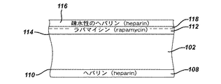
加えて、ステントのヘパリン被膜はステント植え込み後における亜急性の血栓症を減少するという付加的な利点を有すると思われる(セリュイズ(Serruys)他,1996年)。したがって、ステントによる狭窄した冠動脈の持続された機械的な拡張は再狭窄の防止の方法を提供することが示されており、ヘパリンによるステントの被覆は薬物を損傷した組織部位に局所的に送達することの実行可能性および臨床的な有用性の両方を立証している。 In addition, the heparin coating of the stent appears to have the added benefit of reducing subacute thrombosis after stent implantation (Serruys et al., 1996). Thus, sustained mechanical dilatation of a stenotic coronary artery with a stent has been shown to provide a method of preventing restenosis, and the coating of a stent with heparin locally delivers the drug to the damaged tissue site Both the feasibility and clinical usefulness of this.
上述のように、ヘパリンを被覆したステントを用いることは局所的な薬剤送達の実行可能性および臨床上の有用性を立証しているが、このような特定の薬物または薬物の組み合わせ物を局所送達装置に固定する様式はこの種の治療の効能においてある役割を果たす必要がある。例えば、薬物/薬物の組み合わせ物を局所送達装置に固定するために用いる方法および材料はその薬物/薬物の組み合わせ物の作用に対して干渉してはならない。さらに、これらの利用する方法および材料は生体適合性である必要があり、送達中および所与の時間の期間にわたり薬物/薬物の組み合わせ物をその局所送達装置に保持する必要がある。例えば、局所送達装置の送達中におけるその薬物/薬物の組み合わせ物の脱落は潜在的にその装置の能力不全を生じる可能性がある。 As noted above, using heparin-coated stents has demonstrated the feasibility and clinical utility of local drug delivery, but local delivery of such specific drugs or drug combinations The mode of fixing to the device needs to play a role in the efficacy of this type of treatment. For example, the methods and materials used to secure a drug / drug combination to a local delivery device should not interfere with the action of the drug / drug combination. In addition, these utilized methods and materials must be biocompatible and hold the drug / drug combination in its local delivery device during delivery and for a given period of time. For example, shedding of the drug / drug combination during delivery of a local delivery device can potentially cause the device to fail.
したがって、例えば、アテローム硬化症のように生物学的に誘発されるか、または、たとえば、経皮的冠動脈形成術を介して機械的に誘発される、内膜の肥厚化を生じる脈管の損傷の防止および治療のための薬物/薬物の組み合わせ物および関連の局所送達装置に対する要望が存在している。加えて、送達および位置付け中に薬物/薬物の組み合わせ物を局所送達装置において保持すること、および所与の時間の期間にわたり治療的投薬量で薬物/薬物の組み合わせ物を放出することを確実に行なうことに対する要望が存在している。 Thus, vessel damage resulting in intimal thickening that is biologically induced, eg, atherosclerosis, or mechanically induced, eg, via percutaneous coronary angioplasty There is a need for drug / drug combinations and related local delivery devices for the prevention and treatment of cancer. In addition, it ensures that the drug / drug combination is retained in the local delivery device during delivery and positioning and that the drug / drug combination is released at a therapeutic dosage over a given period of time. There is a desire for that.
内膜の肥厚化を引き起こす傷害の防止および治療のための多様なステント被膜および配合物が提案されている。これらの被膜はそれ自体でステントが損傷した内腔壁に与える刺激を減少することができ、それゆえ、血栓症または再狭窄への傾向を低下することができる。あるいは、上記の被膜は平滑筋組織の増殖または再狭窄を減少する医薬品/治療薬または薬物を内腔に送達することも可能である。この薬剤送達のメカニズムはバルクポリマーまたはそのポリマーの構造中に形成されている細孔による薬剤の拡散、または、生体分解性の被膜の浸食により行われる。 A variety of stent coatings and formulations have been proposed for the prevention and treatment of injuries that cause intimal thickening. These coatings can themselves reduce irritation to the damaged lumen wall by the stent and thus reduce the tendency to thrombosis or restenosis. Alternatively, the coating can deliver a pharmaceutical / therapeutic agent or drug to the lumen that reduces smooth muscle tissue proliferation or restenosis. This mechanism of drug delivery is accomplished by diffusion of the drug through the bulk polymer or pores formed in the polymer structure, or by erosion of the biodegradable coating.
ステント用の被膜として生体吸収性で生体安定性の配合物が報告されている。これらの配合物は一般に、医薬品/治療薬または薬物、例えば、ラパマイシン、タクソール等を包み込むか、このような物質をその表面、例えば、ヘパリン被覆型のステントに結合する種々のポリマー被膜であった。これらの被膜は浸漬法、噴霧法またはスピンコート法を含むがこれらに限定されない多くの方法でステントに供給される。 Bioabsorbable and biostable formulations have been reported as stent coatings. These formulations were generally various polymer coatings that encapsulate pharmaceutical / therapeutic agents or drugs, such as rapamycin, taxol, etc., or that bind such materials to their surfaces, such as heparin-coated stents. These coatings are applied to the stent in a number of ways, including but not limited to dipping, spraying, or spin coating.
ステント用の被膜として報告されている生体安定性の材料の一例はポリフルオロホモポリマーである。ポリテトラフルオロエチレン(PTFE)ホモポリマーは長年にわたりインプラント材料として用いられている。これらのホモポリマーは適当な温度においてはいずれの溶剤にも溶解せず、それゆえ、上記装置の重要な特徴部分(例えば、ステントにおけるスロット部分)を維持しながら小形の各種医療装置にコーティングすることが困難である。 An example of a biostable material that has been reported as a coating for stents is polyfluorohomopolymer. Polytetrafluoroethylene (PTFE) homopolymer has been used as an implant material for many years. These homopolymers do not dissolve in any solvent at the appropriate temperature, and therefore can be applied to a variety of small medical devices while maintaining the critical features of the device (eg, the slot portion of the stent). Is difficult.
ポリフッ化ビニリデンのホモポリマーにより作成されていて、放出するための医薬品/治療薬または薬物を含有している被膜を伴うステントがこれまでに提案されている。しかしながら、大抵の結晶質ポリフルオロホモポリマーと同様に、これらの被膜は、これらをそのポリマーの融点に相当する比較的に高い温度にしない場合には、(ステントの)表面上に高品質なフィルムとして供給することが困難である。 Stents with pharmaceutical / therapeutic or drug-containing coatings made of polyvinylidene fluoride homopolymers for release have been previously proposed. However, like most crystalline polyfluorohomopolymers, these coatings are high quality films on the surface (of the stent) if they are not brought to a relatively high temperature corresponding to the melting point of the polymer. It is difficult to supply as.
血栓症、再狭窄またはその他の有害な反応を軽減し、このような作用を達成するために種々の医薬品または治療薬または薬物の使用を含むことができるが必ずしもこれを必要とせず、種々の被覆型装置が比較的に低い最高温度にかけられる時でも、これらの装置において使用することに有効である物理的および機械的な諸特性を有することのできる植え込み可能な種々の医療装置のための被膜を開発することが有利になると考えられる。また、疾患を治療し、医療装置の植え込みに対する生体反応を最小限にするか実質的に起こさせない種々の薬物、薬剤および/または配合物との組み合わせにおける植え込み可能な医療装置を開発することも有利と考えられる。特定の状況において、創傷の治癒および医療装置における内皮化を助長する種々の薬物、薬剤および/または配合物との組み合わせにおける植え込み可能な医療装置を開発することも有利になると考えられる。 Can reduce but not necessarily require the use of various pharmaceuticals or therapeutic agents or drugs to reduce thrombosis, restenosis or other adverse reactions and achieve such effects Coatings for various implantable medical devices that can have physical and mechanical properties that are effective for use in these devices even when the mold devices are subjected to relatively low maximum temperatures It would be advantageous to develop. It would also be advantageous to develop an implantable medical device in combination with various drugs, agents and / or formulations that treats the disease and minimizes or does not substantially cause a biological response to the implantation of the medical device. it is conceivable that. In certain circumstances, it may also be advantageous to develop implantable medical devices in combination with various drugs, agents and / or formulations that promote wound healing and endothelialization in medical devices.
また、上記の被膜または医療装置自体に悪影響を及ぼすことなく種々の被覆型の植え込み可能な医療装置の送達を行なう送達装置を開発することも有利になると考えられる。加えて、このような送達装置は上記医療装置を標的領域内に容易にかつ正確に位置付けするための手段を医者に必然的に提供する。 It would also be advantageous to develop a delivery device that delivers various types of implantable medical devices without adversely affecting the coating or the medical device itself. In addition, such delivery devices necessarily provide the physician with a means for easily and accurately positioning the medical device within the target area.
また、植え込み可能な医療装置からの種々の薬物、薬剤および/または配合物の溶出速度の正確な制御を可能にする植え込み可能な医療装置のための被膜を開発することも有利になると考えられる。 It would also be advantageous to develop a coating for an implantable medical device that allows precise control of the dissolution rate of various drugs, agents and / or formulations from the implantable medical device.
また、細胞増殖に影響を及ぼす異なる分子レベルのメカニズムを通して作用する1種類以上の薬剤の放出を行なう送達装置を開発することも有利になると考えられる。 It would also be advantageous to develop a delivery device that releases one or more drugs that act through different molecular mechanisms that affect cell growth.
また、アテローム硬化性プラークの治療のための1種類以上の薬剤の限局的(regional)投与を行なう送達装置を開発することも有利になると考えられる。 It would also be advantageous to develop a delivery device that provides regional administration of one or more drugs for the treatment of atherosclerotic plaque.
薬物の効果および送達性を増す薬物の液体調合物を開発することも有利になると考えられる。特に、水に不溶性で親油性の薬物の液体の溶液の投薬形態は、相当量の界面活性剤、補助溶媒等に頼ることなく、作ることが困難である。 It would also be advantageous to develop liquid formulations of drugs that increase the effectiveness and delivery of the drug. In particular, dosage forms of liquid solutions of water-insoluble and lipophilic drugs are difficult to make without resorting to significant amounts of surfactants, co-solvents, and the like.
相当な問題の別の種類の脈管の疾患はアテローム硬化症である。このアテローム硬化症は動脈の肥厚化および硬化であり、一般に、例えば、コレステロール等の脂肪性の物質、炎症性の細胞、細胞性老廃物、動脈の内膜または内壁内のカルシウムおよびその他の物質の、進行性の蓄積により生じると考えられている。これらの刺激性の物質の蓄積はさらに、罹患した動脈の壁部の中の細胞を刺激して、障害部位の成長につながる細胞のさらなる蓄積を結果として生じる付加的な物質を生成させる。この蓄積または障害部位は一般にプラークと呼ばれている。 Another type of vascular disease of considerable concern is atherosclerosis. This atherosclerosis is an arterial thickening and sclerosis, generally involving, for example, fatty substances such as cholesterol, inflammatory cells, cellular waste products, calcium and other substances in the intima or inner wall of arteries. It is thought to be caused by progressive accumulation. The accumulation of these stimulating substances further stimulates cells in the walls of the affected arteries to produce additional substances that result in further accumulation of cells leading to the growth of the lesion site. This site of accumulation or injury is commonly referred to as a plaque.
最近の研究は、アテローム硬化症の理解に変化を導いて、まだ十分に治療されていない別の重要な脈管の問題を明らかにしている。科学者は、少なくとも一部の冠状動脈疾患が炎症性の過程であると理論付けており、この場合に、炎症はプラークを不安定にして破裂させる。このような炎症を起こしたプラークはアテローム不安定プラーク(atherosclerotic vulnerable plaque)として知られている。 Recent studies have led to changes in the understanding of atherosclerosis and uncover another important vascular problem that has not yet been fully treated. Scientists have theorized that at least some coronary artery disease is an inflammatory process, where inflammation destabilizes and ruptures the plaque. Such inflamed plaques are known as atherosclerotic vulnerable plaques.
不安定プラークは平滑筋細胞の薄い層により被覆されている高脂肪のコアからなっている。これらの不安定プラークは破裂しやすくて浸食を受けやすく、上記の薄い細胞層が破裂するか、潰瘍になると、かなりの梗塞を引き起こす可能性がある。炎症性の細胞が浸食を受けるか、破裂すると、その脂肪のコアは血流に曝されて、その動脈内に血栓を形成する。これらの血栓は速やかに成長して、その動脈を遮断するか、分離して下流側に移動して、塞栓性の現象、不安定なアンギナ、心筋梗塞、および/または急死を引き起こす。実際に、一部の最近の研究では、プラークの破裂が、全ての致命的な心筋梗塞の内の60〜70%を引き起こす可能性がある、と示唆している。なお、不安定プラークのさらに詳細な説明については、キャンベル(Campbell)に発行されている米国特許第5,924,997号およびキャンベル(Campbell)他に発行されている米国特許第6,245,026号を参照されたい。 Vulnerable plaque consists of a high fat core covered by a thin layer of smooth muscle cells. These vulnerable plaques are prone to rupture and are susceptible to erosion and can cause considerable infarction if the thin cell layer ruptures or becomes ulcerated. When inflammatory cells are eroded or ruptured, the fat core is exposed to the bloodstream and forms a thrombus in the artery. These thrombi grow quickly and block or separate their arteries, causing embolic phenomena, unstable angina, myocardial infarction, and / or sudden death. In fact, some recent studies suggest that plaque rupture can cause 60-70% of all fatal myocardial infarctions. For a more detailed description of vulnerable plaque, see US Pat. No. 5,924,997 issued to Campbell and US Pat. No. 6,245,026 issued to Campbell et al. Please refer to the issue.
アテローム硬化症を検出するために用いられている初期の方法は、心臓の患者における不安定プラークを可視化して確認するための診断器具を欠いていた。しかしながら、新しい診断技法は、冠動脈内の不安定プラークの位置を確認するために開発中である。これらの新しい装置は、精密な磁気共鳴画像法(MRI)、炎症の過程が熱を発生するという仮定において動脈壁部の温度を測定する熱センサー、弾性センサー、脈管内超音波、光干渉トモグラフィ(OCT)、造影剤、および近赤外および赤外光、を含む。しかしながら、現在において明らかでないことは、不安定プラークの障害部位が見つかった後にこれらを治療する方法である。 Early methods used to detect atherosclerosis lacked diagnostic tools for visualizing and confirming vulnerable plaque in cardiac patients. However, new diagnostic techniques are being developed to confirm the location of vulnerable plaque within the coronary arteries. These new devices include precision magnetic resonance imaging (MRI), thermal sensors that measure arterial wall temperature, assuming that the inflammatory process generates heat, elastic sensors, intravascular ultrasound, optical interference tomography (OCT), contrast agents, and near infrared and infrared light. However, what is not clear at the present time is how to treat sites of vulnerable plaque after they have been found.
従来のステント処理に続いてバルーン血管形成を用いることにより不安定プラークを治療することは十分とは言えない結果を生じることになるであろう。すなわち、バルーン血管形成は、それ自体により、不安定プラークを破裂させて、下層の新しい組織細胞、コラーゲンまたは損傷した内皮、を血流に対して露出させる可能性がある。この状況は、血管を部分的にまたは完全に閉塞させる血栓または血液凝固物の形成に、最終的につながる。加えて、裸の被覆されていないステントは不安定プラークの上に保護カバーを与える新内膜過形成を誘発するが、再狭窄が、元の不安定プラークよりも、患者をさらに危険にする可能性がある重要な問題として残る。 Treating vulnerable plaque by using balloon angioplasty following conventional stenting will produce less than satisfactory results. That is, balloon angioplasty can itself rupture vulnerable plaque and expose the underlying new tissue cells, collagen or damaged endothelium, to the bloodstream. This situation ultimately leads to the formation of a thrombus or blood clot that partially or completely occludes the blood vessel. In addition, bare uncoated stents induce neointimal hyperplasia that provides a protective cover over vulnerable plaque, but restenosis can make the patient even more dangerous than the original vulnerable plaque It remains as an important problem.
したがって、不安定プラークおよび関連の脈管の疾患を有効に治療する薬物溶出式ステントまたはその他の医療装置を開発することが有利になると考えられる。 Accordingly, it would be advantageous to develop a drug eluting stent or other medical device that effectively treats vulnerable plaque and related vascular disease.
したがって、治療剤の溶出特性を有効に調整すると考えられる新しい方法を開発して、その治療剤の安定性を増すことも、有利になると考えられる。 Therefore, it would also be advantageous to develop new methods that would effectively adjust the elution characteristics of a therapeutic agent to increase the stability of the therapeutic agent.
〔発明の概要〕
本発明の治療剤の溶出調整方法は、治療剤の溶出特性を調整する方法、に関連している。この方法において用いられているアニール法は、記載されている溶出特性を達成するために役立ち、比較的に良好な治療剤の安定性を生じ、したがって、上記において簡単に説明されている不都合点を解消する。
[Summary of the Invention]
The method for adjusting the dissolution of a therapeutic agent of the present invention relates to a method for adjusting the dissolution characteristics of a therapeutic agent. The annealing method used in this method helps to achieve the described elution characteristics and results in a relatively good therapeutic agent stability, thus avoiding the disadvantages briefly described above. Eliminate.
本発明の一態様によれば、上記の溶出特性と、少なくとも1種類の治療剤の安定性と、を調整するための方法は、治療の投薬量の少なくとも1種類の物質、および少なくとも1種類のポリマー材料(polymeric material)を含む、第1の被膜を、植え込み可能な構造体に、供給する工程と、この第1の被膜を、上記少なくとも1種類のポリマー(polymer)の最高のガラス転移温度(Tg )よりも、実質的に高い温度まで、アニールする工程と、を含む。 According to one aspect of the present invention, a method for adjusting the elution characteristics described above and the stability of at least one therapeutic agent comprises at least one substance in a therapeutic dosage, and at least one substance. Supplying a first coating comprising a polymeric material to the implantable structure and applying the first coating to the highest glass transition temperature of the at least one polymer ( Annealing to a temperature substantially higher than T g ).
本発明の別の態様によれば、薬物溶出式の医療装置のための方法は、植え込み可能な医療装置と、上記装置に供給されている被膜であって、治療の投薬量の少なくとも1種類の物質、および少なくとも1種類のポリマー材料を含む、被膜と、当該第1の被膜を、上記少なくとも1種類のポリマーの最高のガラス転移温度(Tg )よりも、実質的に高い温度まで、アニールする処理と、を含む。 In accordance with another aspect of the present invention, a method for a drug eluting medical device is an implantable medical device and a coating provided on the device, the method comprising at least one therapeutic dosage. Annealing the coating and the first coating comprising a material and at least one polymer material to a temperature substantially higher than a maximum glass transition temperature (T g ) of the at least one polymer. Processing.
薬物、薬剤および/または配合物(compounds)の種々の組み合わせ物が種々の状況を治療するために利用できる。例えば、ラパマイシン(rapamycin)およびトリコスタチンA(trichostatin A)は脈管の傷害後の再狭窄を治療または予防するために利用できる。ラパマイシン(rapamycin)およびトリコスタチンA(trichostatin A)は、細胞増殖に影響を及ぼす異なる分子レベルのメカニズムを通して作用するので、これらの物質は、薬物溶出式のステントにおいて組み合わされる場合に、異なる複数のメカニズムにより、平滑筋および免疫細胞の増殖(炎症性細胞の増殖)の両方をダウンレギュレーションすることにより、互いの抗再狭窄性の活性(anti-restenotic activity)を高めることが可能である。このようなトリコスタチンA(trichostatin A)によるシロリムス(sirolimus)の抗増殖性の活性の増強は、脈管再生およびその他の脈管の外科処置中の脈管の傷害後の抗再狭窄性の効力における向上、およびこの抗再狭窄性の効果を得るために必要とされるそれぞれの物質の量の減少と、言い換えることができる。 Different combinations of drugs, agents and / or compounds can be used to treat different situations. For example, rapamycin and trichostatin A can be used to treat or prevent restenosis after vascular injury. Because rapamycin and trichostatin A act through different molecular-level mechanisms that affect cell proliferation, these substances may have different mechanisms when combined in drug-eluting stents. Thus, it is possible to enhance each other's anti-restenotic activity by down-regulating both smooth muscle and immune cell proliferation (proliferation of inflammatory cells). Such enhancement of sirolimus antiproliferative activity by trichostatin A is effective for anti-restenosis after vascular injury during vascular regeneration and other vascular surgical procedures. In other words, and a reduction in the amount of each substance required to obtain this anti-restenotic effect.
トリコスタチンA(trichostatin A)は人間の冠状動脈平滑筋の細胞増殖の完全で有効な遮断により、局所的な脈管への適用(例えば、ステントまたはカテーテルに基づく送達)により新内膜の形成を遮断できる。上記のシロリムス(sirolimus)とトリコスタチンA(trichostatin A)(および、その薬理学的な種類の範囲内の別の薬剤)との組み合わせ物は、ラパマイシン(rapamycin)単独よりも、さらに再狭窄/新内膜の肥圧化に対して有効であると考えられる新しい治療用の組み合わせ物を代表している。加えて、この組み合わせ物の異なる用量は、ラパマイシン(rapamycin)およびトリコスタチンA(trichostatin A)の単純な添加の作用よりも、新内膜の増殖の抑制の付加的な利益を生じることができる。さらにこのラパマイシン(rapamycin)とトリコスタチンA(trichostatin A)との組み合わせ物は、アテローム硬化症の不安定プラーク(vulnerable atherosclerotic plaque)等のような別の心臓脈管の病気に対して有効である可能性がある。 Trichostatin A is a complete and effective blockade of human coronary artery smooth muscle cell proliferation that can be applied to local vessels (eg, stent or catheter-based delivery) to form neointima. Can be blocked. The above combination of sirolimus and trichostatin A (and another drug within its pharmacological range) is more restenotic / new than rapamycin alone. It represents a new therapeutic combination that is considered effective for intimal hypertension. In addition, different doses of this combination can produce an additional benefit of inhibiting neointimal growth over the effect of simple addition of rapamycin and trichostatin A. Furthermore, this combination of rapamycin and trichostatin A may be effective against other cardiovascular diseases such as atherosclerotic plaques. There is sex.
別の代替的で例示的な実施形態において、ラパマイシン(rapamycin)はミコフェノール酸(mycophenolic acid)との組み合わせにおいて利用可能である。ラパマイシン(rapamycin)およびミコフェノール酸(mycophenolic acid)は、細胞周期の異なる段階において、細胞増殖に影響を及ぼす異なる分子レベルのメカニズムを通して作用するので、これらの物質は、薬物溶出式のステントまたは本明細書において定められているような任意の他の医療装置において組み合わされる場合に、異なるメカニズムにより、平滑筋および免疫細胞の増殖の両方をダウンレギュレーションすることにより、互いの抗再狭窄性の活性を高めることが可能である。 In another alternative exemplary embodiment, rapamycin can be utilized in combination with mycophenolic acid. Since rapamycin and mycophenolic acid act through different molecular-level mechanisms that affect cell proliferation at different stages of the cell cycle, these substances are either drug-eluting stents or Enhances each other's anti-restenotic activity by down-regulating both smooth muscle and immune cell proliferation by different mechanisms when combined in any other medical device as defined in the document It is possible.
さらに別の代替的で例示的な実施形態において、ラパマイシン(rapamycin)はクラドリビン(cladribine)との組み合わせにおいて利用可能である。ラパマイシン(rapamycin)およびクラドリビン(cladribine)は、細胞周期の異なる段階において、細胞増殖に影響を及ぼす異なる分子レベルのメカニズムを通して作用するので、これらの物質は、薬物溶出式のステントまたは本明細書において定められているような任意の他の医療装置において組み合わされる場合に、異なるメカニズムにより、平滑筋および免疫細胞の増殖の両方をダウンレギュレーションすることにより、互いの抗再狭窄性の活性を高めることが可能である。本質的に、上記のラパマイシン(rapamycin)とクラドリビン(cladribine)との組み合わせ物は、いずれかの物質の単独またはこれら2種類の薬剤の効果の単純な合計よりも、さらに有効であると考えられる治療用の組み合わせ物を代表している。加えて、この組み合わせ物の異なる用量は、ラパマイシン(rapamycin)またはクラドリビン(cladribine)単独よりも、新内膜の増殖の抑制の付加的な利益を生じることができる。 In yet another alternative exemplary embodiment, rapamycin may be utilized in combination with cladribine. Because rapamycin and cladribine act through different molecular-level mechanisms that affect cell proliferation at different stages of the cell cycle, these substances are defined as drug-eluting stents or as defined herein. When combined in any other medical device such as, it is possible to enhance each other's anti-restenotic activity by down-regulating both smooth muscle and immune cell proliferation by different mechanisms It is. In essence, the combination of rapamycin and cladribine described above is considered to be more effective than either substance alone or a simple sum of the effects of these two drugs. Represents a combination for. In addition, different doses of this combination can produce an additional benefit of inhibiting neointimal growth over rapamycin or cladribine alone.
さらに別の代替的で例示的な実施形態において、ラパマイシン(rapamycin)は、イリノテカン(irinotecan)、カンプトセシン(camptothecin)、カンプトサル(camptosar)およびDX−8951fを含む、トポテカン(topotecan)または他のトポイソメラーゼ(topoisomerase)I抑制因子、との組み合わせにおいて利用可能である。ラパマイシン(rapamycin)およびトポテカン(topotecan)は、細胞周期の異なる段階において、細胞増殖に影響を及ぼす異なる分子レベルのメカニズムを通して作用するので、これらの物質は、薬物溶出式のステントまたは本明細書において定められているような任意の他の医療装置において組み合わされる場合に、異なる複数のメカニズムにより、平滑筋細胞および免疫細胞の増殖(炎症性細胞の増殖)の両方をダウンレギュレーションすることにより、互いの抗再狭窄性の活性を高めることが可能である。本質的に、上記のラパマイシン(rapamycin)とトポテカン(topotecan)または他のトポイソメラーゼ(topoisomerase)I抑制因子との組み合わせ物は、いずれかの物質の単独またはこれら2種類の薬剤の効果の単純な合計よりも、さらに有効であると考えられる治療用の組み合わせ物を代表している。加えて、この組み合わせ物の異なる用量は、ラパマイシン(rapamycin)またはトポテカン(topotecan)単独よりも、新内膜の増殖の抑制の付加的な利益を生じることができる。 In yet another alternative exemplary embodiment, the rapamycin is a topotecan or other topoisomerase, including irinotecan, camptothecin, camptosar, and DX-8951f. ) It can be used in combination with I inhibitor. Because rapamycin and topotecan act through different molecular-level mechanisms that affect cell proliferation at different stages of the cell cycle, these substances are defined as drug-eluting stents or as defined herein. When combined in any other medical device such as, the anti-mutation of each other by down-regulating both smooth muscle cell and immune cell proliferation (proliferation of inflammatory cells) by different mechanisms. It is possible to increase restenotic activity. In essence, the above combination of rapamycin and topotecan or other topoisomerase I inhibitor is more than a simple sum of the effects of either substance alone or these two drugs. Are also representative of therapeutic combinations that are believed to be more effective. In addition, different doses of this combination can result in an additional benefit of inhibiting neointimal growth over rapamycin or topotecan alone.
さらに別の代替的で例示的な実施形態において、ラパマイシン(rapamycin)は、ポドフィロトキシン(podophyllotoxin)およびその誘導体およびテニポシド(teniposide)を含む、エトポシド(etoposide)または他の細胞増殖抑制性グルコシド、との組み合わせにおいて利用可能である。ラパマイシン(rapamycin)およびエトポシド(etoposide)は、細胞周期の異なる段階において、細胞増殖に影響を及ぼす異なる分子レベルのメカニズムを通して作用するので、これらの物質は、薬物溶出式のステントまたは本明細書において定められているような任意の他の医療装置において組み合わされる場合に、異なる複数のメカニズムにより、平滑筋細胞および免疫細胞の増殖(炎症性細胞の増殖)の両方をダウンレギュレーションすることにより、互いの抗再狭窄性の活性を高めることが可能である。本質的に、上記のラパマイシン(rapamycin)と、ポドフィロトキシン(podophyllotoxin)およびその誘導体およびテニポシド(teniposide)を含む、エトポシド(etoposide)または他の細胞増殖抑制性グルコシドとの組み合わせ物は、いずれかの物質の単独またはこれら2種類の薬剤の効果の単純な合計よりも、さらに有効であると考えられる治療用の組み合わせ物を代表している。加えて、この組み合わせ物の異なる用量は、ラパマイシン(rapamycin)またはエトポシド(etoposide)単独よりも、新内膜の増殖の抑制の付加的な利益を生じることができる。 In yet another alternative exemplary embodiment, rapamycin is etoposide or other cytostatic glucoside, including podophyllotoxin and its derivatives and teniposide, Can be used in combination. Since rapamycin and etoposide act through different molecular-level mechanisms that affect cell proliferation at different stages of the cell cycle, these substances are defined as drug-eluting stents or as defined herein. When combined in any other medical device such as, the anti-mutation of each other by down-regulating both smooth muscle cell and immune cell proliferation (proliferation of inflammatory cells) by different mechanisms. It is possible to increase restenotic activity. Essentially any combination of the above rapamycin with etoposide or other cytostatic glucosides, including podophyllotoxin and its derivatives and teniposide It represents a therapeutic combination that is considered to be even more effective than a single substance or a simple sum of the effects of these two drugs. In addition, different doses of this combination can result in the added benefit of inhibiting neointimal growth over rapamycin or etoposide alone.
さらに別の代替的で例示的な実施形態において、2−メトキシエストラジオール(2-methoxyestraiol)またはパンゼム(Panzem)(登録商標)は、脈管の傷害後の再狭窄を予防するために、単独またはラパマイシン(rapamycin)との組み合わせにおいて、利用可能である。ラパマイシン(rapamycin)またはシロリムス(sirolimus)およびパンゼム(Panzem)(登録商標)は、異なる分子レベルのメカニズムを通して細胞増殖を抑制するように作用するので、これらの物質は、薬物溶出式のステントまたは本明細書において定められているような任意の他の医療装置において組み合わされる場合に、異なる複数のメカニズムにより、平滑筋および免疫細胞の増殖の両方をダウンレギュレーションすることにより、互いの抗再狭窄性の活性を高めることが可能である。本質的に、上記のラパマイシン(rapamycin)とパンゼム(Panzem)(登録商標)または他のエストロゲン受容体モジュレーターとの組み合わせ物は、いずれかの物質の単独またはこれら2種類の薬剤の効果の単純な合計よりも、さらに有効であると考えられる治療用の組み合わせ物を代表している。加えて、この組み合わせ物の異なる用量は、ラパマイシン(rapamycin)またはパンゼム(Panzem)(登録商標)単独よりも、新内膜の増殖の抑制の付加的な利益を生じることができる。 In yet another alternative exemplary embodiment, 2-methoxyestraiol or Panzem® is used alone or rapamycin to prevent restenosis after vascular injury It can be used in combination with (rapamycin). Since rapamycin or sirolimus and Panzem® act to inhibit cell proliferation through different molecular-level mechanisms, these substances can be used in drug-eluting stents or Anti-restenotic activity of each other by down-regulating both smooth muscle and immune cell proliferation by different mechanisms when combined in any other medical device as defined in the It is possible to increase. In essence, the above combination of rapamycin and Panzem® or other estrogen receptor modulators is a simple sum of the effects of either substance alone or these two drugs. It represents a therapeutic combination that is considered to be even more effective. In addition, different doses of this combination may produce an additional benefit of inhibiting neointimal growth over rapamycin or Panzem® alone.
さらに別の代替的で例示的な実施形態において、ラパマイシン(rapamycin)はシロスタゾール(cilostazol)との組み合わせにおいて利用可能である。このラパマイシン(rapamycin)およびシロスタゾール(cilostazol)の組み合わせ物は、平滑筋細胞の増殖および移動の両方の減少において、いずれかの薬物の単独よりも、さらに有効である可能性がある。加えて、この組み合わせ物の被膜からのシロスタゾール(cilostazol)の放出は、血液接触式の医療装置の表面上における長期の抗血小板付着および抗塞栓形成を達成するために、持続された様式で、調整できる。この場合に、上記組み合わせ物の被膜の中におけるシロスタゾール(cilostazol)の混合は、ラパマイシン(rapamycin)を伴う単一の層の中、あるいは、ラパマイシン(rapamycin)を含有している層の外側の別の層の中、の両方において、構成できる。 In yet another alternative exemplary embodiment, rapamycin can be utilized in combination with cilostazol. This combination of rapamycin and cilostazol may be more effective than either drug alone in reducing both smooth muscle cell proliferation and migration. In addition, cilostazol release from the coating of this combination is regulated in a sustained manner to achieve long-term antiplatelet adhesion and anti-embolization on the surface of blood contact medical devices it can. In this case, the mixing of cilostazol in the coating of the combination can be done in a single layer with rapamycin or another layer outside the layer containing rapamycin. It can be configured both in the layer.
さらに別の代替的で例示的な実施形態において、ラパマイシン(rapamycin)はPI3キナーゼ抑制因子との組み合わせにおいて利用可能である。本発明は、脈管の傷害の適用における新内膜の過形成を防ぐための、単独またはシロリムス(sirolimus)との組み合わせにおける、PI3キナーゼ抑制因子の使用を記載している。このシロリムス(sirolimus)およびPI3キナーゼ抑制因子は発散性の抗増殖性のメカニズムを通して作用するので、これらの薬剤は、薬物溶出式ステントにおいて組み合わされると、異なる複数のメカニズムによって、平滑筋細胞および免疫細胞の増殖(炎症性細胞の増殖)の両方をダウンレギュレーションすることにより、互いの抗再狭窄性の活性を増強する可能性がある。このような、PI3キナーゼ抑制因子によるシロリムス(sirolimus)の抗増殖性の活性の増強は、脈管再生およびその他の脈管の外科処置の間における脈管の傷害後の抗再狭窄性の効果における向上と、この抗再狭窄性の効果を達成するためのいずれかの薬剤の必要とされる量における減少と、言い換えることができる。 In yet another alternative exemplary embodiment, rapamycin may be utilized in combination with a PI3 kinase inhibitor. The present invention, for preventing neointimal hyperplasia in vascular injury applications, alone or in combination with sirolimus (the sirolimus), describes the use of PI3 kinase inhibition factor. Because this sirolimus and PI3 kinase inhibitor act through a divergent antiproliferative mechanism, these drugs, when combined in drug-eluting stents, have different mechanisms by which smooth muscle cells and immune cells By down-regulating both the proliferation of inflammatory cells (proliferation of inflammatory cells), it is possible to enhance each other's anti-restenotic activity. Such enhancement of the antiproliferative activity of sirolimus by PI3 kinase inhibitors in the antirestenotic effect after vascular injury during vascular regeneration and other vascular surgical procedures In other words, an improvement and a reduction in the required amount of any drug to achieve this anti-restenotic effect.
本発明の、医療装置、薬物被膜、送達装置、および当該送達装置の上に薬物被膜またはビヒクルを維持するための方法は、疾患や、疾患またはその他の状況の治療のための医療装置の植え込みによる生体の反応、を治療するために、材料の組み合わせ物を利用している。この薬物、薬剤または配合物の局所的な送達は一般に、それぞれの効果を増しながら、全身系的な送達に比べた場合に、それらの薬物、薬剤または配合物の潜在的な毒性を実質的に減少させる。 The medical device, drug coating, delivery device, and method for maintaining a drug coating or vehicle on the delivery device of the present invention is by implanting a medical device for the treatment of a disease or disease or other condition A combination of materials is used to treat a biological response. This local delivery of drugs, agents or formulations generally increases the effectiveness of each while substantially reducing the potential toxicity of those drugs, agents or formulations when compared to systemic delivery. Decrease.
薬物、薬剤または配合物は、種々の疾患を治療するために、多数の医療装置に固定できる。これらの薬物、薬剤または配合物はまた、別の状況を治療するために利用されている医療装置の導入による生物学的な生体反応を最小限にするか実質的に起こさせないために固定することも可能である。例えば、ステントは冠動脈や、胆管等のような、別の体内腔を開くために導入できる。これらのステントの導入は平滑筋細胞の増殖作用ならびに炎症を引き起こす。したがって、これらのステントは、上記のような反応に対処するために、薬物、薬剤または配合物により被覆できる。特定の種類の外科手術において日常的に用いられている、吻合装置もまた、平滑筋細胞の増殖作用ならびに炎症を引き起こす可能性がある。また、ステントグラフトおよび、例えば、動脈瘤バイパスシステム等の、ステントグラフトを利用しているシステムは、これらの装置の導入により引き起こされる有害な影響を防ぎ、治癒や取り込みを促進させるために、薬物、薬剤および/または配合物により被覆できる。それゆえ、これらの装置はまた、これらの反応に対処するために、薬物、薬剤および/または配合物により被覆することも可能である。加えて、動脈瘤バイパスシステム等のような装置は、創傷治癒および内皮化を促進させる薬物、薬剤および/または配合物により被覆することにより、内部漏れの危険性やその他の類似の現象を減少させる。 A drug, agent or formulation can be fixed to a number of medical devices to treat various diseases. These drugs, agents or compounds should also be fixed in order to minimize or substantially not cause biological biological reactions due to the introduction of medical devices that are used to treat other situations Is also possible. For example, a stent can be introduced to open another body lumen, such as a coronary artery, a bile duct, or the like. The introduction of these stents causes smooth muscle cell proliferation and inflammation. Thus, these stents can be coated with drugs, agents or formulations to address such reactions. Anastomotic devices, routinely used in certain types of surgery, can also cause smooth muscle cell proliferation and inflammation. Also, stent grafts and systems utilizing stent grafts, such as, for example, aneurysm bypass systems, prevent the harmful effects caused by the introduction of these devices and promote the healing, uptake, And / or coated with a formulation. Therefore, these devices can also be coated with drugs, agents and / or formulations to address these reactions. In addition, devices such as aneurysm bypass systems etc. reduce the risk of endoleaks and other similar phenomena by coating with drugs, agents and / or compounds that promote wound healing and endothelialization .
上記薬物、薬剤または配合物は、医療装置の種類、医療装置の導入に対する反応および/または治療することが求められている疾患に応じて、変更する。また、これらの薬物、薬剤または配合物を医療装置に固定するために利用される被膜やビヒクルの種類も、その医療装置の種類、薬物、薬剤または配合物の種類、およびこれらの放出の速度を含む、さまざまな要素に応じて、変更してもよい。 The drug, agent or formulation will vary depending on the type of medical device, the response to the introduction of the medical device and / or the disease sought to be treated. Also, the type of coating or vehicle utilized to secure these drugs, agents or formulations to the medical device also determines the type of medical device, the type of drug, agent or formulation, and the rate of their release. It may be changed according to various factors including.
有効であるために、上記の薬物、薬剤または配合物は、送達や植え込みの間に、医療装置に留まっていることが当然に好ましい。したがって、これらの薬物、薬剤または配合物の間の強い結合を形成するための種々のコーティング技法(coating techniques)が利用できる。加えて、薬物、薬剤または配合物が時期尚早に脱離することを防ぐための表面改質剤として、種々の物質を利用できる。 In order to be effective, it is of course preferred that the drug, agent or formulation remains in the medical device during delivery or implantation. Thus, various coating techniques are available to form strong bonds between these drugs, agents or formulations. In addition, various materials can be utilized as surface modifiers to prevent premature release of drugs, agents or formulations.
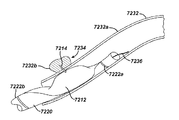
あるいは、上記被覆された植え込み可能な医療装置のための送達装置は、その被膜または装置自体に対する損傷の潜在的な危険性を最小限にするために、改良できる。例えば、自己拡張式ステントを配備することに付随する摩擦力を減少させるために、ステント送達装置に対する種々の改良を行なうことができる。具体的に、上記送達装置は種々の物質により被覆することが可能であり、あるいは、被覆されたステントの特定の領域における力の作用を減少させるための特徴を含んでいてよい。 Alternatively, the delivery device for the coated implantable medical device can be modified to minimize the potential risk of damage to the coating or the device itself. For example, various improvements to the stent delivery device can be made to reduce the frictional forces associated with deploying self-expanding stents. Specifically, the delivery device can be coated with a variety of materials, or may include features to reduce the action of force in a particular region of the coated stent.
本発明の自己拡張式ステントの送達システムは、熱分解カーボンまたは類似の物質の層により被覆されているシース、を備えている。この熱分解カーボンの層は、ステントの領域の中のシースの内腔にまたはそのシースの全長に沿って、固定できる。この熱分解カーボンは、自己拡張式のステントが、比較的に軟質のポリマー・シースの中に埋め込まれることを防ぐために、十分に硬質である。加えて、上記熱分解カーボンは潤滑性の材料である。これらの2種類の特性は、配備中のステントに対する損傷の変化を減少させると共に、ステントの配備のために必要とされる力を減少させ、これにより、医者が、配置を達成して、さらに正確なステントの配備を行なうことを容易にしている。 The self-expanding stent delivery system of the present invention comprises a sheath coated with a layer of pyrolytic carbon or similar material. This pyrolytic carbon layer can be secured to the lumen of the sheath in the area of the stent or along the entire length of the sheath. This pyrolytic carbon is sufficiently hard to prevent the self-expanding stent from being embedded in a relatively soft polymer sheath. In addition, the pyrolytic carbon is a lubricious material. These two characteristics reduce the change in damage to the stent during deployment and reduce the force required for stent deployment, which allows the physician to achieve placement and make it more accurate. It is easy to deploy a simple stent.
上記の熱分解カーボンは、シースの内腔に直接固定されるか、あるいは、後にシースの内腔に固定される支持体(substrate)に直接固定され得る。種々の既知の技法が上記の製造方法において利用可能である。熱分解カーボンは生体適合性であり、多数の植え込み可能な医療装置の中において、現在、利用されている。この熱分解カーボンの層は、上述の特徴を備えるために十分に厚いが、全体のプロファイルおよび送達システムの柔軟性を維持するために十分に薄い。 The pyrolytic carbon can be fixed directly to the lumen of the sheath or directly to a substrate that is subsequently fixed to the lumen of the sheath. Various known techniques are available in the above manufacturing method. Pyrolytic carbon is biocompatible and is currently utilized in many implantable medical devices. This layer of pyrolytic carbon is thick enough to have the features described above, but thin enough to maintain the overall profile and flexibility of the delivery system.
上記熱分解カーボンの潤滑性は、薬物被覆型ステントにおいて、特に有利である。この薬物の被膜、および薬物、薬剤または配合物、を含有しているポリマーは、好ましくは、最良の結果のために、ステントに留まる必要がある。シース上の潤滑性の被膜は、薬物またはポリマーが送達中に擦れ落ちる危険性を、実質的に減少させる。 The lubricity of the pyrolytic carbon is particularly advantageous in drug-coated stents. The drug coating, and the polymer containing the drug, agent or compound, should preferably remain on the stent for best results. A lubricious coating on the sheath substantially reduces the risk of drug or polymer scrubbing during delivery.
本発明の自己拡張性ステントの送達システムは、改良された軸部(shaft)を備えていてもよい。この改良された軸部は、ステント要素の間の隙間の中に、その軸部から突出する複数の要素、を含んでいてよい。これらの要素は、ステントの圧縮を防ぐか実質的に減少させることにより、配備中にステントに作用する力をかなり減少させることができる。これら複数の要素が無ければ、そのステントは送達システムの内側の軸部における停止部材に対して移動してこれを圧縮する可能性がある。さらに、このステントの圧縮は、比較的に高い配備の力を生じる。したがって、複数の要素を有する軸部はステントの長さ方向の移動を無くすか実質的に減少させ、これにより、上記のような圧縮を無くすか実質的に減少させる。加えて、上記の突出している要素は、これら複数の要素にわたって、ステントに作用する全体の力を分配するので、ステントおよびその上のあらゆる被膜における局在化した応力が少なくなる。 The self-expanding stent delivery system of the present invention may include an improved shaft. The improved shaft may include a plurality of elements projecting from the shaft in the gap between the stent elements. These elements can significantly reduce the forces acting on the stent during deployment by preventing or substantially reducing stent compression. Without these multiple elements, the stent may move and compress against a stop member on the inner shaft of the delivery system. Furthermore, this compression of the stent produces a relatively high deployment force. Thus, a shaft having a plurality of elements eliminates or substantially reduces stent longitudinal movement, thereby eliminating or substantially reducing compression as described above. In addition, the protruding elements distribute the overall force acting on the stent across the plurality of elements, thereby reducing localized stresses on the stent and any coating thereon.
本発明の植え込み可能な医療装置の表面を被覆するための組成物は、薬物放出に対する化学的および物理的なバリアを与える被膜を達成するために、2種類の化学的に異なるポリマーの組み合わせ物、を用いている。この組み合わせ物は、耐久性および潤滑性であり、上記被膜の中に含有されているあらゆる薬物、薬剤、および/または配合物の溶出速度について、制御を行なう。 The composition for coating the surface of the implantable medical device of the present invention comprises a combination of two chemically different polymers to achieve a coating that provides a chemical and physical barrier to drug release, Is used. This combination is durable and lubricious and provides control over the dissolution rate of any drug, agent, and / or formulation contained in the coating.
微小針または、灌流バルーン等のような、他のカテーテル型送達システムは、アテローム硬化性プラークの部位に、ラパマイシン(rapamycin)を含む、1種類以上の薬物、薬剤および/または配合物を送達するために利用できる。この種の限局的送達は、単独で、または、植え込み可能な医療装置とこれに固定されている同種または異種の薬物との組み合わせにおいて、利用できる。上記の1種類以上の薬物、薬剤および/または配合物は好ましくは、病巣に最も近い外膜の空間(adventitial space)に送達される。 Other catheter-type delivery systems, such as microneedles or perfusion balloons, to deliver one or more drugs, agents and / or compounds, including rapamycin, at the site of atherosclerotic plaque Available to: This type of localized delivery can be used alone or in combination with an implantable medical device and the same or different drugs anchored thereto. The one or more drugs, agents and / or formulations described above are preferably delivered to the adventitial space closest to the lesion.
ラパマイシン(rapamycin)等のような、有効な治療剤の、局所的または限局的に送達される溶液は、全身系的に送達される薬剤や植え込み可能な医療装置により送達される薬剤よりも、多数の利点を提供する。例えば、動脈壁内に薬剤を直接に付着させることにより、比較的に高い組織濃度を達成できる。沈着の位置により、異なる薬物濃度プロファイルを、薬物溶出式ステントのプロファイルによるよりも、達成することができる。加えて、局所的にまたは限局的に送達される溶液により、ステント等のような永久に植え込まれる装置に対する必要性がなくなり、これにより、炎症反応や長期間の組織の損傷等のような、ステントに伴う潜在的な副作用を無くなる。しかしながら、この局所的にまたは限局的に送達される溶液が、薬物溶出式ステントや他の被覆型の植え込み可能な医療装置との組み合わせにおいて利用可能であることを注目することが重要である。さらに、溶液または液体配合物の別の利点は、その液体調合物中の賦形剤の調節が薬物の分布および保持のプロファイルを容易に変えるという事実において、存在している。加えて、上記液体調合物は、投与形態の保管および貯蔵寿命を改善するために、予め包装された多数チャンバー式の注入装置により、注入の直前に混合してもよい。 Solutions that are delivered locally or locally for effective therapeutic agents, such as rapamycin, are more numerous than drugs delivered systemically or by implantable medical devices. Provide the benefits of. For example, relatively high tissue concentrations can be achieved by attaching the drug directly into the arterial wall. Depending on the location of deposition, different drug concentration profiles can be achieved than with drug-eluting stent profiles. In addition, locally or locally delivered solutions eliminate the need for permanently implanted devices such as stents and the like, such as inflammatory reactions and long-term tissue damage, Eliminate potential side effects associated with stents. However, it is important to note that this locally or locally delivered solution can be used in combination with drug-eluting stents and other coated implantable medical devices. Furthermore, another advantage of solution or liquid formulations exists in the fact that adjustment of excipients in the liquid formulation easily alters the distribution and retention profile of the drug. In addition, the liquid formulation may be mixed immediately prior to injection by a pre-packaged multi-chamber infusion device to improve the storage and shelf life of the dosage form.
不安定プラークは脈管の疾患であり、この場合に、高脂質のコアが平滑筋細胞の薄い層により被覆されている。これらの不安定プラークは破裂または侵食しやすく、薄い炎症性の細胞の層が破裂するか潰瘍になると、かなりの梗塞を引き起こす可能性がある。炎症性の細胞が侵食されるか、破裂すると、脂質のコアは血流に曝されて、その動脈の中に血栓を形成する。これらの血栓は速やかに成長して、その動脈を遮断するか、分離して下流に移動して、塞栓症の状況、不安定なアンギナ、心筋梗塞、および/または急死、につながる。本発明は、血管の開通性を維持するように設計されている支持骨格構造に関連しており、この支持骨格構造は、不安定プラークの破裂および脂質コアの代謝に付随する、炎症およびその他の病状を治療するための、1種類以上の治療用の薬物、薬剤および/または配合物、を含有しているポリマー被膜構造、を含む。抗炎症性の治療用の薬物、薬剤および/または配合物は、疾患の炎症性で急性の状態に対処するために、速やかな放出のための、被膜構造の中に組み込むことが可能であり、脂質を低下させる薬物、薬剤、および/または配合物は、疾患の慢性の状態に対処するために、ゆっくりとした放出のための、被膜構造の中に混合できる。加えて、複数の薬物を、相乗効果を与えるために、組み合わせることも可能である。また、これらの異なる薬物は、疾患の異なる状況において作用するために、異なるメカニズムを通して、作用する。 Vulnerable plaque is a vascular disease, in which a high lipid core is covered by a thin layer of smooth muscle cells. These vulnerable plaques are prone to rupture or erosion and can cause considerable infarction when a thin layer of inflammatory cells ruptures or becomes ulcerated. When inflammatory cells are eroded or ruptured, the lipid core is exposed to the bloodstream and forms a thrombus in the artery. These thrombi grow quickly and either block their arteries or separate and move downstream, leading to an embolic situation, unstable angina, myocardial infarction, and / or sudden death. The present invention relates to a scaffold structure designed to maintain vascular patency, which is associated with inflammation and other associated with rupture of vulnerable plaque and metabolism of the lipid core. A polymer coating structure containing one or more therapeutic drugs, agents and / or formulations for treating a medical condition. Anti-inflammatory therapeutic drugs, agents and / or formulations can be incorporated into the coating structure for rapid release to address the inflammatory and acute conditions of the disease; Lipid-lowering drugs, agents, and / or formulations can be mixed into the coating structure for slow release to address the chronic condition of the disease. In addition, multiple drugs can be combined to provide a synergistic effect. Also, these different drugs act through different mechanisms to act in different situations of the disease.
本発明の上記およびその他の特徴および利点が以下の添付図面において例示されている本発明の好ましい実施形態のさらに詳しい説明により明らかになるであろう。 The above and other features and advantages of the present invention will become apparent from the following more detailed description of the preferred embodiment of the present invention, which is illustrated in the accompanying drawings.
〔好ましい実施形態の詳細な説明〕
本発明の薬物/薬物の組み合わせおよび送達装置は、脈管の疾患、特に傷害により生じた脈管の疾患を効果的に予防および治療するために利用できる。脈管の疾患の治療において利用されている種々の医療用の治療装置は、最終的にさらに別の合併症を誘発する可能性がある。例えば、バルーン脈管形成術は動脈の中を通る血流を増加するために利用されている処置であり、冠状動脈の狭窄における主要な治療方法である。しかしながら、上述のように、この処置は脈管壁部に対してある程度の損傷を生じるために、ある程度の時間の経過後に、その問題を潜在的に悪化させる可能性がある。また、別の処置および疾患も同様の傷害の原因になる可能性があるが、本発明の例示的な実施形態は、経皮的冠動脈形成術およびその他の、類似の動脈、静脈およびこれら以外の流体運搬導管を含む、別の類似の動脈/静脈処置に続いて生じる再狭窄および関連の合併症の治療に関して説明されている。加えて、被覆型の医療装置の効果的な送達のための種々の方法および装置が説明されている。
Detailed Description of Preferred Embodiments
The drug / drug combination and delivery device of the present invention can be used to effectively prevent and treat vascular diseases, particularly vascular diseases caused by injury. Various medical treatment devices utilized in the treatment of vascular disease can eventually induce additional complications. For example, balloon angioplasty is a procedure that has been utilized to increase blood flow through arteries and is the primary treatment method for coronary stenosis. However, as mentioned above, this procedure can cause some damage to the vessel wall, potentially potentially exacerbating the problem after some time. In addition, although other treatments and diseases can cause similar injury, exemplary embodiments of the present invention include percutaneous coronary angioplasty and other similar arteries, veins and others The treatment of restenosis and related complications following another similar arterial / venous procedure involving a fluid delivery conduit has been described. In addition, various methods and devices have been described for effective delivery of coated medical devices.
本発明の例示的な実施形態は経皮的冠動脈形成術に続いて生じる再狭窄および関連の合併症の治療に関して説明されているが、上記薬物/薬物の組み合わせの局所的な送達が多数の医療装置を利用して多用な状況を治療すること、またはその装置の機能および/または寿命を高めること、のために利用できることに注目することが重要である。例えば、白内障の手術後の視力を回復するために配置される眼内レンズは二次的な白内障の形成により損なわれる場合が多い。後者はレンズ表面の上における細胞の過剰成長の結果である場合が多く、その装置に対する1種類以上の薬物の結合により潜在的に最小にすることができる。さらに、装置の内部、上部およびその周囲における組織の内部増殖またはタンパク質様の物質の堆積により故障する場合の多い別の医療装置、例えば、水頭症用のシャント、透析グラフト(dialysis graft)、結腸瘻袋取付装置、耳ドレナージ管、ペースメーカーおよび植え込み可能な除細動器用のためのリード線等もまた上記のような装置−薬物の組み合わせの方法により恩恵を受けることができる。また、組織または器官の構造および機能を改善するために役立つ装置も、適当な1種類以上の薬剤と組み合わされる場合に種々の有益性を示すことができる。例えば、植え込まれた装置の安定性を高めるための改善された整形外科装置の骨一体化機能が、その装置を骨−形態形成性のタンパク質等のような物質と組み合わせることにより潜在的に達成可能になる。同様に、別の外科装置、縫合糸、ステープル、吻合装置、椎骨ディスク、骨ピン、縫合糸アンカー、止血用バリア、クランプ、ねじ、プレート、クリップ、脈管インプラント、組織接着剤および密封材、組織支持骨格材料、種々の包帯、骨置換材料、内腔内装置、および脈管支持体もまた、上記のような薬物−装置の組み合わせの方法により患者の有益性を高めることができる。特に、脈管周囲ラップは単独または他の医療装置との組み合わせにおいて有利であると考えられる。すなわち、このような脈管周囲ラップは治療部位に対して付加的な薬物を供給することができる。本質的に、任意の種類の医療装置がその装置または薬剤の1回の使用期間の全体にわたり治療効果を高める薬物または薬物の組み合わせにより、ある様式で被覆できる。 Although exemplary embodiments of the present invention have been described with respect to the treatment of restenosis and related complications following percutaneous coronary angioplasty, local delivery of the above drug / drug combination is a number of medical treatments. It is important to note that the device can be used to treat a wide variety of situations, or to increase the function and / or lifetime of the device. For example, intraocular lenses that are placed to restore visual acuity after cataract surgery are often impaired by the formation of secondary cataracts. The latter is often the result of cell overgrowth on the lens surface and can potentially be minimized by the binding of one or more drugs to the device. In addition, other medical devices that often fail due to tissue ingrowth or deposition of proteinaceous material in, around and around the device, such as hydrocephalus shunts, dialysis grafts, colon fistulas Bag attachment devices, ear drainage tubes, pacemakers, lead wires for implantable defibrillators, etc. can also benefit from such device-drug combination methods. Devices that help to improve the structure and function of tissues or organs can also exhibit various benefits when combined with one or more suitable drugs. For example, an improved orthopedic device bone integration function to enhance the stability of the implanted device is potentially achieved by combining the device with a material such as a bone-morphogenic protein. It becomes possible. Similarly, another surgical device, suture, staple, anastomosis device, vertebral disk, bone pin, suture anchor, hemostatic barrier, clamp, screw, plate, clip, vascular implant, tissue adhesive and sealant, tissue Supporting skeletal materials, various bandages, bone replacement materials, endoluminal devices, and vascular supports can also increase patient benefit by the method of drug-device combination as described above. In particular, perivascular wraps are considered advantageous when used alone or in combination with other medical devices. That is, such a perivascular wrap can deliver additional drug to the treatment site. In essence, any type of medical device can be coated in some manner with a drug or combination of drugs that enhances the therapeutic effect throughout the single use period of the device or drug.
種々の医療装置に加えて、これらの装置における被膜は治療薬および薬剤を送達するために用いることができ、これらの治療薬および薬剤は、ビンカアルカロイド類(vinca alkaloids)(すなわち、ビンブラスチン(vinblastine)、ビンクリスチン(vincristine)、およびビノレルビン(vinorelbine))等のような天然産物、パクリタキセル(paclitaxel)、エピジポドフィルロトキシン類(epidipodophyllotoxins)(すなわち、エトポシド(etoposide)、テニポシド(teniposide))、抗生物質(すなわち、ダクチノマイシン(dactinomycin)(アクチノマイシンD(actinomycin D))、ダウノルビシン(daunorubicin)、ドキソルビシン(doxorubicin)およびイダルビシン(idarubicin))、アントラサイクリン(anthracyclines)、ミトキサントロン(mitoxantrone)、ブレオマイシン(bleomycins)、プリカマイシン(plicamycin)(ミトラマイシン(mithramycin))およびマイトマイシン(mitomycin)、酵素(L−アスパラギン(L-asparagine)を全身系的に代謝し、独自にアスパラギン(asparagine)を合成する機能をもたない細胞を奪取するL−アスパラギナーゼ等)を含む抗増殖/抗有糸分裂剤、G(GP)IIb/IIIa抑制因子およびビトロネクチン(vitronectin)受容体拮抗物質等のような抗血小板剤、ナイトロジェンマスタード(nitrogen mustards)(メクロレタミン(mechlorethamine)、シクロホスファミド(cyclophosphamide)およびその類似体、メルファラン(melphalan)、クロラムブシル(chlorambucil))、エチレンイミン(ethyleneimines)およびメチルメラミン(methylmelamines)(ヘキサメチルメラミン(hexamethylmelamine)およびチオテパ(thiotepa))、スルホン酸アルキル類−ブスルファン複合物(alkyl sulfonates-busulfan)、ニトロソ尿素類(nitrosoureas)(カルムスチン(carmustine)(BCNU)およびその類似体、ストレプトゾシン(streptozocin))、トラゼン−ダカルバジニン複合物(trazenes-dacarbazinine)(DTIC)等のような抗増殖/抗有糸分裂アルキル化剤、葉酸類似体(メトトレキサート(methotrexate))、ピリミジン類似体(フルオロウラシル(fluorouracil)、フロクスウリジン(floxuridine)およびシタラビン(cytarabine))、プリン類似体および関連の抑制因子(メルカプトプリン(mercaptopurine)、チオグアニン(thioguanine)、ペントスタチン(pentostatin)および2−クロロデオキシアデノシン(2-chlorodeoxyadenosine){クラドリビン(cladribine)})、白金配位錯体(platinum coodination complexes)(シスプラチン(cisplatin)、カルボプラチン(carboplatin))、プロカルバジン(procarbazine)、ヒドロキシ尿素(hydroxyurea)、ミトテン(mitotane)、アミノグルテチミド(aminoglutethimide)等のような抗増殖/抗有糸分裂代謝拮抗物質、ホルモン類(すなわち、エストロゲン(estrogen))、抗凝固薬(ヘパリン(heparin)、合成ヘパリン塩類(synthetic heparin salts)およびその他のトロンビンの抑制物質)、フィブリン溶解剤(組織プラスミノゲン活性化因子(tissue plasminogen activator)、ストレプトキナーゼ(streptokinase)およびウロキナーゼ(urokinase)等)、アスピリン(aspirin)、ジピリダモール(dipyridamole)、チクロピジン(ticlopidine)、クロピドグレル(clopidogrel)、アブシキシマブ(abciximab)、抗遊走薬(antimigratory)、抗分泌薬(ブレベルジン(breveldin))、さらに、副腎皮質ステロイド(コルチゾール(cortisol)、コルチゾン(cortisone)、フルドロコルチゾン(fludrocortisone)、プレドニゾン(prednisone)、プレドニゾロン(prednisolone)、6α−メチルプレドニゾロン(6α-methylprednisolone)、トリアムシノロン(triamcinolone)、ベタメタゾン(betamethasone)、およびデキサメタゾン(dexamethasone))、非ステロイド性薬剤(サリチル酸誘導体(salicylic acid derivatives)、すなわち、アスピリン(aspirin)、パラアミノフェノール誘導体(para-aminophenol derivatives)、すなわち、アセトアミノフェン(acetaminophen))等のような抗炎症薬、インドールおよびインデン酢酸(indole and indene acetic acids)(インドメタシン(indomethacin)、スリンダク(sulindac)、およびエトダラック(etodalac))、ヘテロアリール酢酸(トルメチン(tolmetin)、ジクロフェナク(dicrofenac)およびケトロラク(ketorolac))、アリールプロピオン酸(イブプロフェン(ibuprofen)およびその誘導体)、アントラニル酸(メフェナム酸(mefenamic acid)およびメクロフェナム酸(meclofenamic acid))、エノール酸(enolic acids)(ピロキシカム(piroxicam)、テノキシカム(tenoxicam)、フェニルブタゾン(phenylbutazone)、およびオキシフェンタトラゾン(oxyphenthatrazone))、ナブメトン(nabumetone)、金化合物(オーラノフィン(auranofin)、金チオグルコース(aurothioglucose)、金チオリンゴ酸ナトリウム(gold sodium thiomalate))、免疫抑制剤、すなわち、(シクロスポリン(cyclosporine)、タクロリムス(tacrolimus)(FK−506)、シロリムス(sirolimus)(ラパマイシン(rapamycin))、アザチオプリン(azathioprine)、ミコフェノール酸モフェチル(mycophenolate mofetil))、脈管形成剤、すなわち、血管内皮細胞増殖因子(VEGF)、線維芽細胞増殖因子(FGF)、アンギオテンシン受容体遮断薬、一酸化窒素供与体、アンチセンス・オリゴヌクレオチド類およびこれらの組み合わせ、細胞周期抑制因子、mTOR抑制因子、および増殖因子受容体信号伝達キナーゼ抑制因子(growth factor receptor signal transduction kinase inhibitor)、レテノイド(retenoid)、サイクリン/CDK抑制因子、HMG補酵素還元酵素阻害剤(スタチン類(statins))、およびプロテアーゼ阻害剤等、を含む。 In addition to various medical devices, the coatings on these devices can be used to deliver therapeutic agents and drugs, such as vinca alkaloids (ie, vinblastine) , Natural products such as vincristine and vinorelbine, paclitaxel, epidipodophyllotoxins (ie, etoposide, teniposide), antibiotics Substances (ie, dactinomycin (actinomycin D), daunorubicin, doxorubicin and idarubicin), anthracyclines, mitoxantrone, bleomycin (Bleomyci ns), plicamycin (mitramycin), mitomycin, and the enzyme (L-asparagine) are systematically metabolized and synthesized asparagine independently. antiproliferative / antimitotic agents including cells to take L- asparaginase, etc.) without, G (GP) II b / III a inhibitors and vitronectin (vitronectin) receptor antiplatelet agents such as antagonists , Nitrogen mustards (mechlorethamine, cyclophosphamide and analogs thereof, melphalan, chlorambucil), ethyleneimines and methylmelamines ( Hexamethylmelamine and thiotepa) Alkyl sulfonates-busulfan complexes, nitrosoureas (carmustine (BCNU) and its analogs, streptozocin), trazenes-dacarbazinine ) (DTIC) and other anti-proliferative / anti-mitotic alkylating agents, folic acid analogs (methotrexate), pyrimidine analogs (fluorouracil, floxuridine and cytarabine)) , Purine analogs and related inhibitors (mercaptopurine, thioguanine, pentostatin and 2-chlorodeoxyadenosine {cladribine}), platinum coordination complexes ( platinum coodination complexes) ( Anti-proliferative / anti-mitotic antimetabolites, hormones such as splatin, carboplatin, procarbazine, hydroxyurea, mitotane, aminoglutethimide, etc. (Ie, estrogen), anticoagulants (heparin, synthetic heparin salts and other thrombin inhibitors), fibrinolytic agents (tissue plasminogen activator) , Streptokinase and urokinase, etc.), aspirin, dipyridamole, ticlopidine, clopidogrel, abciximab, antisecretory (antimigratory) Breveldi n)) and further corticosteroids (cortisol, cortisone, fludrocortisone, prednisone, prednisolone, 6α-methylprednisolone, triamcinolone ), Betamethasone, and dexamethasone), non-steroidal drugs (salicylic acid derivatives), ie aspirin, para-aminophenol derivatives, ie, acetaminophen ( anti-inflammatory drugs such as acetaminophen), indole and indene acetic acids (indomethacin, sulindac, etodalac), heteroaryl acetic acid Tolmetin, diclofenac and ketorolac), arylpropionic acid (ibuprofen and its derivatives), anthranilic acid (mefenamic acid and meclofenamic acid), enolic acid ( enolic acids (piroxicam, tenoxicam, phenylbutazone, and oxyphenthatrazone), nabumetone, gold compounds (auranofin, gold thioglucose ( aurothioglucose, gold sodium thiomalate), immunosuppressants, ie (cyclosporine, tacrolimus (FK-506), sirolimus (rapamycin), azathioprine azathioprine), mycophenolate mofetil), angiogenic agents, ie, vascular endothelial growth factor (VEGF), fibroblast growth factor (FGF), angiotensin receptor blocker, nitric oxide donor, Antisense oligonucleotides and combinations thereof, cell cycle inhibitors, mTOR inhibitors, growth factor receptor signal transduction kinase inhibitors, retenoids, cyclin / CDK inhibitors HMG coenzyme reductase inhibitors (statins), protease inhibitors, and the like.
上述のように、バルーン脈管形成術と関連している冠状動脈ステントの植え込みは急性の脈管閉塞の治療において極めて有効であり、再狭窄の危険性を減少させることができる。脈管内超音波調査に関する研究(ミンツ(Mintz)他,1996年)は、冠状動脈ステント処理が脈管の狭窄を有効に防止すること、およびステント植え込み後における術後内腔損失の大部分がプラークの増殖によるものであり、恐らくは新内膜過形成に関連していること、を示唆している。この冠状動脈ステント処理後の術後内腔損失率は従来のバルーン脈管形成術の後に観察される量のほぼ2倍高い。したがって、ステントが再狭窄の過程の少なくとも一部分を妨げる限りにおいて、平滑筋細胞の増殖を阻止し、炎症を軽減して凝固を減少させるか、または、多数のメカニズムにより平滑筋細胞の増殖を阻止するか、ステントと組み合わされて炎症を軽減して凝固を減少させる、薬物、薬剤または配合物の組み合わせは、脈管形成術後の再狭窄に対する最も効力のある治療方法を提供する可能性がある。また、同種または異種の薬物/薬物の組み合わせの局所的な送達との組み合わせにおける薬物、薬剤または配合物の全身系的な使用も有益な治療の選択肢を与える可能性がある。 As described above, coronary stent implantation associated with balloon angioplasty is extremely effective in treating acute vascular occlusion and can reduce the risk of restenosis. A study on intravascular ultrasound studies (Mintz et al., 1996) found that coronary stenting effectively prevented vascular stenosis and that most postoperative lumen loss after stent implantation was plaque. Suggests that it is related to neointimal hyperplasia. The postoperative lumen loss rate after this coronary stenting is almost twice as high as that observed after conventional balloon angioplasty. Therefore, as long as the stent prevents at least part of the restenosis process, it prevents smooth muscle cell proliferation, reduces inflammation and reduces coagulation, or prevents smooth muscle cell proliferation by multiple mechanisms Alternatively, a combination of drugs, agents or compounds that combine with a stent to reduce inflammation and reduce coagulation may provide the most effective treatment for restenosis after angioplasty. Systemic use of drugs, agents or formulations in combination with local delivery of the same or different drug / drug combinations may also provide beneficial therapeutic options.
ステントからの薬物/薬物の組み合わせの局所的な送達は以下の利点、すなわち、ステントの支持骨格作用による脈管の反跳および再造形の防止、新内膜の過形成または再狭窄の多くの発生要素の阻止ならびに炎症および血栓症の軽減という利点を、有している。さらに、上記のようなステント処理した冠状動脈への薬物、薬剤または配合物の局所的な投与はさらに付加的な治療上の有益性を有することもできる。例えば、薬物、薬剤または配合物の、組織における比較的に高い濃度は、全身系的な投与ではなく、局所的な送達を利用することにより達成できる。加えて、減少された全身系的な毒性は、全身系的な投与ではなく、組織における比較的に高い濃度を維持しながら、局所的な送達を利用することにより達成できる。また、全身系的な投与の代わりに、ステントによる局所的な送達を利用することにおいて、1回の処置で、比較的に良好な患者の応諾感に対して十分に対応できる。さらに、上記のような薬物、薬剤、および/または配合物の組み合わせによる治療の付加的な有益性は治療用の薬物、薬剤または配合物のそれぞれの投薬量を減少させることができることであり、これにより、それぞれの毒性を制限すると共に、再狭窄、炎症および血栓症の軽減を達成できる。それゆえ、上記のような局所的なステントに基づく治療方法は抗再狭窄性、抗炎症性、または抗血栓性の薬物、薬剤または配合物の治療率(効力/毒性)を改善する手段である。 Local delivery of a drug / drug combination from a stent has the following advantages: prevention of vascular recoil and remodeling due to the stent's support skeletal action, many occurrences of neointimal hyperplasia or restenosis It has the advantage of blocking elements and reducing inflammation and thrombosis. In addition, local administration of drugs, agents or compounds to stented coronary arteries as described above may have additional therapeutic benefits. For example, a relatively high concentration of a drug, agent or formulation in a tissue can be achieved by utilizing local delivery rather than systemic administration. In addition, reduced systemic toxicity can be achieved by utilizing local delivery while maintaining relatively high concentrations in the tissue rather than systemic administration. Also, by utilizing local delivery by a stent instead of systemic administration, a single treatment can adequately address relatively good patient compliance. Furthermore, an additional benefit of treatment with a combination of drugs, agents and / or formulations as described above is that the respective dosage of the therapeutic drug, agent or formulation can be reduced. Can limit their respective toxicities and reduce restenosis, inflammation and thrombosis. Therefore, local stent-based therapies as described above are a means of improving the therapeutic rate (efficacy / toxicity) of anti-restenotic, anti-inflammatory, or anti-thrombotic drugs, agents or compounds. .
経皮的冠動脈形成術に続いて利用できる多数の異なるステントが存在する。このような多数のステントを本発明にしたがって利用することが可能であるが、簡明化のために、限定された数のステントが本発明の例示的な実施形態において説明されている。なお、当業界における熟練者であれば、任意数のステントが本発明に関連して利用可能であることが認識できるであろう。加えて、上述のように、別の医療装置も利用可能である。 There are a number of different stents available following percutaneous coronary angioplasty. Although many such stents can be utilized in accordance with the present invention, for the sake of clarity, a limited number of stents are described in the exemplary embodiments of the present invention. One skilled in the art will recognize that any number of stents may be used in connection with the present invention. In addition, as described above, other medical devices can be used.
ステントは一般的に、障害を軽減するために管路の内腔の中に留置される管状の構造体として用いられる。一般的に、ステントは非拡張状態の形態で内腔の中に挿入された後に、自律的に、または、原位置における第2の装置の補助により、拡張する。代表的な拡張の方法は、拡張状態の内腔を得るために、脈管の壁部の構成要素に付随している障害物を剪断および破壊するように、狭窄した脈管または体内の通路の中において膨張されるカテーテル取付型の脈管形成バルーンの使用により行なわれている。 Stents are commonly used as tubular structures that are placed in the lumen of a duct to mitigate damage. In general, a stent is expanded autonomously or with the assistance of a second device in situ after being inserted into the lumen in an unexpanded form. A typical method of dilatation is for a narrowed vessel or body passageway to shear and destroy obstacles associated with vascular wall components to obtain an expanded lumen. This is done by using a catheter-mounted angioplasty balloon that is inflated therein.
図1は、本発明の例示的な実施形態にしたがって利用可能である例示的なステント100を示している。この拡張可能な円筒形のステント100は、血管、管路または内腔を開口状態に保つためにその血管、管路または内腔の中に配置するための、特に、血管形成術後に動脈の一部分を再狭窄から保護するための、有窓構造を含む。このステント100は円周方向に拡張されて、拡張した形態に維持されることが可能であり、円周方向または半径方向に剛性になる。さらに、このステント100は軸方向に柔軟であり、その帯域部分において曲がる場合に、このステント100は外部に突出する構成部分を含まないようになっている。
FIG. 1 illustrates an
上記ステント100は一般に第1の端部および第2の端部、およびこれらの端部の間の中間部分を有している。さらに、このステント100は長さ方向軸を有していて、複数の長さ方向に配置された帯域部分102を含んでおり、それぞれの帯域部分102は上記長さ方向軸に対して平行な線分に沿って概ね連続的な波形を定めている。さらに、円周方向に配列されている複数の連結部材104が各帯域部分102を実質的に管状の構造に維持している。本質的に、長さ方向に配置されているそれぞれの帯域部分102は、複数の周期的な位置において、短い円周方向に沿って配列されている連結部材104を介して、隣接している帯域部分102に接続している。これらの帯域部分102のそれぞれに付随している波形はその中間部分において概ね同一の基本的な空間的周波数を有しており、これらの帯域部分102は、互いに概ね同一の位相になるように、これらに付随する波形が概ね整合するように配置されている。図示のように、長さ方向に配列されているそれぞれの帯域部分102は隣接している帯域部分102に対する連結部分が存在するまでの間にほぼ2周期で波打ちしている。
The
上記ステント100は多数の方法を利用して作成することができる。例えば、このステント100はレーザー、放電フライス加工(electric discharge milling)、化学的エッチングまたはその他の手段により、機械加工可能である中空のまたは成型処理されているステンレス・スチールの管により作成できる。このようなステント100は体内に挿入されて、非拡張状態の形態で所望の部位に配置される。一例の例示的な実施形態において、拡張はバルーン・カテーテルにより血管内において行なうことができ、この場合に、そのステント100の最終的な直径はその使用するバルーン・カテーテルの直径の関数である。
The
本発明のステント100が、例えば、ニッケルおよびチタンの適切な合金またはステンレス・スチールを含む、形状記憶材料において実施可能であることが認識される必要がある。さらに、このようなステンレス・スチールにより形成される構造は、例えば、このステンレス・スチール材料を編み組み状の形態にねじることによる等の、所定の様式でそのステンレス・スチールを構成することにより、自己拡張式にすることができる。このような実施形態においては、ステント100を形成した後に、このステントを圧縮して挿入手段により血管またはその他の組織の中への挿入を可能するために十分に小さい空間部分を占めるようにすることが可能であり、この場合に、その挿入手段は適当なカテーテルまたは柔軟な棒材を含む。さらに、カテーテルから出た後に、上記ステント100は所望の形態に拡張するように構成することができ、この場合に、その拡張は自動的であるか、圧力、温度または電気等の刺激の変化により開始される。
It should be appreciated that the
図2は、図1に示すステント100を利用している本発明の例示的な実施形態を示している。図示のように、このステント100は、1個以上の貯蔵部分106を有するように変更可能である。これらの貯蔵部分106のそれぞれは要望に応じて開閉できる。さらに、これらの貯蔵部分106は送達される薬物/薬物の組み合わせを保持するように特別に設計できる。また、このようなステント100の設計とは無関係に、病巣の領域中に有効な投薬量を供給するために十分な特性および十分な濃度で供給される上記の薬物/薬物の組み合わせの投薬量を有することが好ましい。この点に関して、上記の帯域部分102の中の貯蔵部分の大きさは好ましくは上記薬物/薬物の組み合わせの投薬量を所望の場所において所望の量で適切に供給するように寸法付けられている。
FIG. 2 illustrates an exemplary embodiment of the present invention utilizing the
代替的で例示的な実施形態において、上記ステント100の内表面部および外表面部の全体を治療の投薬量における薬物/薬物の組み合わせにより被覆することも可能である。さらに、再狭窄を治療するための薬物ならびに例示的な被覆技法についての詳細な説明が以下において記載されている。しかしながら、このような被覆技法が上記の薬物/薬物の組み合わせに応じて変更可能であることに注目することが重要である。さらに、この被覆技法は上記ステントまたはその他の内腔内医療装置を構成する材料に応じて変更することも可能である。
In an alternative exemplary embodiment, the entire inner and outer surface of the
ラパマイシン(rapamycin)は米国特許第3,929,992号に開示されているようにストレプトミセス属ハイグロスコピカス(Streptomyces hygroscopicus)により生成される大環状トリエン型の抗生物質である。このラパマイシン(rapamycin)は、とりわけ、生体内における脈管平滑筋細胞の増殖を抑制することが知られている。したがって、ラパマイシン(rapamycin)は、特に、生物学的にまたは機械的に媒介される脈管の損傷に続いて、または、哺乳類動物を脈管損傷に罹りやすくすると考えられる状況において、哺乳類動物における内膜平滑筋細胞の過形成、再狭窄、および脈管閉塞の治療に利用することができる。さらに、ラパマイシン(rapamycin)は平滑筋細胞の増殖を抑制するように機能し、脈管壁部の再内皮化を妨げない。 Rapamycin is a macrocyclic triene antibiotic produced by Streptomyces hygroscopicus as disclosed in US Pat. No. 3,929,992. This rapamycin is particularly known to inhibit the proliferation of vascular smooth muscle cells in vivo. Thus, rapamycin is particularly useful in mammals following biological or mechanically mediated vascular damage or in situations where it is believed that the mammal is susceptible to vascular damage. It can be used to treat membrane smooth muscle cell hyperplasia, restenosis, and vascular occlusion. In addition, rapamycin functions to inhibit smooth muscle cell proliferation and does not prevent re-endothelialization of the vascular wall.
上記ラパマイシン(rapamycin)は、脈管形成術により誘発される傷害において放出されるマイトジェン信号に応答して平滑筋の増殖に拮抗することにより、脈管の過形成を軽減する。細胞周期の後期のG1期における増殖因子およびサイトカインにより媒介される平滑筋増殖の抑制はラパマイシン(rapamycin)の作用の主要なメカニズムであると考えられている。しかしながら、ラパマイシン(rapamycin)はまた、全身系的に投与される場合に、T細胞の増殖および分化を阻止することも知られている。このことがそのラパマイシン(rapamycin)の免疫抑制活性およびそのグラフト(graft)拒絶反応を阻止する能力に対応する論拠である。 The rapamycin reduces vascular hyperplasia by antagonizing smooth muscle proliferation in response to mitogenic signals released in injury induced by angioplasty. Inhibition of smooth muscle proliferation mediated by growth factors and cytokines in the late G1 phase of the cell cycle is believed to be a major mechanism of action of rapamycin. However, rapamycin is also known to prevent T cell proliferation and differentiation when administered systemically. This is the rationale corresponding to its immunosuppressive activity of rapamycin and its ability to block graft rejection.
本明細書において用いられる場合に、ラパマイシン(rapamycin)は、ラパマイシン(rapamycin)と、FKBP12およびその他の免疫促進物質に結合してTORの抑制を含むラパマイシン(rapamycin)と同一の薬理学的な諸特性を有する全ての類似体、誘導体および共役体と、を含む。 As used herein, rapamycin is the same pharmacological property of rapamycin as rapamycin, which binds to FKBP12 and other immunostimulatory substances and includes inhibition of TOR. And all analogs, derivatives and conjugates having
ラパマイシン(rapamycin)の抗増殖効果は全身系的な使用により達成できるが、さらに優れた結果がその化合物の局所的送達により達成できる。本質的に、ラパマイシン(rapamycin)はその化合物の近くにある組織の中において作用し、その送達装置からの距離が増大するにつれて効果が減少する。このような作用を利用するために、ラパマイシン(rapamycin)を内腔の壁部に直接的に接触させることが望ましいと考えられる。したがって、好ましい実施形態において、ラパマイシン(rapamycin)はステントまたはその種々の部分の表面上に組み込まれている。本質的に、ラパマイシン(rapamycin)は、好ましくは、図1において示されているステント100の中に組み込まれており、この場合に、このステント100は内腔の壁部に対して接触する。
Although the anti-proliferative effect of rapamycin can be achieved by systemic use, even better results can be achieved by local delivery of the compound. In essence, rapamycin acts in tissues in the vicinity of the compound and its effectiveness decreases with increasing distance from the delivery device. In order to take advantage of these effects, it may be desirable to bring rapamycin into direct contact with the lumen wall. Thus, in a preferred embodiment, rapamycin is incorporated on the surface of the stent or various portions thereof. In essence, rapamycin is preferably incorporated into the
ラパマイシン(rapamycin)は多くの方法においてステント上に組み込むかこれに対して固着させることができる。例示的な実施形態において、ラパマイシン(rapamycin)はポリマー基材(polymeric matrix)の中に直接的に組み込まれて、ステントの外表面部に噴霧される。その後、このラパマイシン(rapamycin)は経時的にそのポリマー基材から溶出して周囲の組織の中に入り込む。このラパマイシン(rapamycin)は、好ましくは少なくとも3日から約6ヶ月までの間にわたり、さらに好ましくは7日〜30日の間にわたり、ステント上に留まっている。 Rapamycin can be incorporated on or affixed to the stent in a number of ways. In an exemplary embodiment, rapamycin is incorporated directly into the polymeric matrix and sprayed onto the outer surface of the stent. The rapamycin then elutes from the polymer substrate over time and enters the surrounding tissue. The rapamycin preferably remains on the stent for at least 3 days to about 6 months, more preferably for 7-30 days.
多数の非侵食性のポリマーがラパマイシン(rapamycin)と共に利用できる。一例の例示的な実施形態において、ラパマイシン(rapamycin)またはその他の治療薬をフィルム形成用のポリフルオロコポリマー中に組み込むことができ、このフィルム形成用のポリフルオロコポリマーは、重合化されたフッ化ビニリデン(vinylidenefluoride)と重合化されたテトラフルオロエチレン(tetrafluoroethylene)とからなる群から選択される、ある量の第1の成分と、この第1の成分とは異なり、当該第1の成分と共重合されることにより上記ポリフルオロコポリマーを生成する、ある量の第2の成分と、を含有しており、この第2の成分は上記ポリフルオロコポリマーに靱性または弾性を賦与することができ、上記第1の成分と第2の成分の相対的な各量は植え込み可能な医療装置の処理において使用するために有効な特性を伴ってこれらから作られる被膜およびフィルムを提供するために有効である。 A number of non-erodible polymers are available with rapamycin. In one exemplary embodiment, rapamycin or other therapeutic agent can be incorporated into a film-forming polyfluoro copolymer, which is polymerized vinylidene fluoride. An amount of a first component selected from the group consisting of (vinylidenefluoride) and polymerized tetrafluoroethylene and, unlike the first component, is copolymerized with the first component An amount of a second component, thereby producing the polyfluoro copolymer, the second component being capable of imparting toughness or elasticity to the polyfluoro copolymer, The relative amounts of the component and the second component are those with characteristics that are useful for use in the treatment of implantable medical devices. Effective to provide coatings and films made from
本発明はポリフルオロコポリマーを含むポリマーの被膜と、例えば、ステントを脈管形成術において用いる場合に血栓および/または再狭窄を減少するために有効な量で上記ポリマーの被膜のフィルムにより被覆されている、例えば、ステント等のような、植え込み可能な医療装置と、を提供している。なお、本明細書において用いられる場合に、ポリフルオロコポリマーは重合化されたフッ化ビニリデン(vinylidenefluoride)と、重合化されたテトラフルオロエチレン(tetrafluoroethylene)とからなる群から選択される、ある量の第1の成分と、この第1の成分とは異なり、当該第1の成分と共重合されることにより上記ポリフルオロコポリマーを生成する、ある量の第2の成分と、を含有しているコポリマーを意味し、この第2の成分は上記ポリフルオロコポリマーに靱性または弾性を賦与することができ、上記第1の成分と第2の成分の相対的な各量は植え込み可能な医療装置の被覆において使用するために有効な特性を伴って上記ポリフルオロコポリマーから作られる被膜およびフィルムを形成するために有効である。 The present invention provides a polymer coating comprising a polyfluoro copolymer and a film of the polymer coating in an amount effective to reduce thrombus and / or restenosis, for example, when a stent is used in angioplasty. For example, an implantable medical device such as a stent. As used herein, the polyfluoro copolymer is an amount of a first selected from the group consisting of polymerized vinylidenefluoride and polymerized tetrafluoroethylene. A copolymer containing one component and an amount of a second component that differs from the first component to form the polyfluoro copolymer upon copolymerization with the first component. This means that the second component can impart toughness or elasticity to the polyfluoro copolymer and the relative amounts of the first component and the second component are used in the coating of an implantable medical device. It is effective to form coatings and films made from the polyfluoro copolymers with properties that are effective to do so.
上記被膜は再狭窄、炎症および/または血栓を軽減するための薬剤または治療薬を含むことができ、これらの被膜により被覆されているステントは種々の薬剤の持続された放出を行なうことができる。本発明の特定のポリフルオロコポリマーの被膜から調製されているフィルムは、その装置の被膜およびフィルムが曝される最高の温度が比較的に低い温度に制限されている場合においても、従来の被覆型の医療装置において必要とされる物理的および機械的な特性を示す。このことは、上記の被膜/フィルムを用いて熱の影響を受けやすい薬剤/治療薬または薬物を送達する場合に、または、上記被膜をカテーテル等のような温度の影響を受けやすい装置に供給する場合に、特に重要である。一方、最高の暴露温度が問題にならない場合、例えば、イトラコナゾール(itraconazole)等のような熱安定性の薬物が被膜中に組み込まれる場合には、比較的に高い融点の熱可塑性のポリフルオロコポリマーを用いることができ、極めて高い伸び率および付着性が必要とされる場合には、エラストマーを用いることができる。このように、望まれる場合または必要とされる場合に、ポリフルオロエラストマーが、例えば、「モダン・フルオロポリマーズ(Modern Fluoropolymers)」,(J.シャイアズ(J. Shires)編集),ジョン・ワイリー・アンド・サンズ(John Wiley & Sons),ニューヨーク,1997年,p.77〜87において記載されている標準的な方法により架橋できる。 The coatings can include drugs or therapeutic agents for reducing restenosis, inflammation and / or thrombus, and stents coated with these coatings can provide sustained release of various drugs. Films prepared from the specific polyfluoro copolymer coatings of the present invention may have conventional coating molds even when the maximum temperature to which the coatings and films of the device are exposed is limited to relatively low temperatures. The physical and mechanical properties required for medical devices are shown. This may be the case when using the coating / film to deliver a heat sensitive drug / therapeutic agent or drug, or to supply the coating to a temperature sensitive device such as a catheter or the like. It is especially important when. On the other hand, if the highest exposure temperature is not an issue, for example, if a thermostable drug such as itraconazole is incorporated into the coating, a relatively high melting point thermoplastic polyfluoro copolymer may be used. If it can be used and very high elongation and adhesion are required, an elastomer can be used. Thus, when desired or required, polyfluoroelastomers can be produced, for example, by “Modern Fluoropolymers” (edited by J. Shires), John Wiley &・ John Wiley & Sons, New York, 1997, p. Crosslinking can be achieved by standard methods described in 77-87.
本発明は医療装置用の改善された生体適合性の被膜またはビヒクルを提供するポリフルオロコポリマーを含む。これらの被膜は再狭窄または血栓、または他の望ましくない反応を軽減するために十分な、例えば、ヒトのような、哺乳類動物の体組織に対して接触するように、不活性な生体適合性の表面部分を賦与する。多くの報告されているポリフルオロホモポリマーにより作成されている被膜は不溶性であり、および/または、植え込み可能な装置、例えば、ステント等において使用する場合に適当な物理的および機械的な特性を備えたフィルムを得るために、例えば、約125℃以上の温度の高い熱を必要とし、または、特定的に靱性または弾性を有していないが、本発明のポリフルオロコポリマーにより調製されているフィルムは、医療装置において形成される場合に、適当な接着性、靱性または弾性および割れに対する耐性を賦与する。また、特定の例示的な実施形態において、上記のことは医療装置が比較的に低い最高温度に曝される場合においても言える。 The present invention includes polyfluoro copolymers that provide improved biocompatible coatings or vehicles for medical devices. These coatings are inert, biocompatible, sufficient to reduce restenosis or thrombus, or other undesirable reactions, such as contact with mammalian body tissue, such as humans. Apply the surface part. Coatings made with many reported polyfluorohomopolymers are insoluble and / or have suitable physical and mechanical properties for use in implantable devices such as stents. For example, films that require high heat at temperatures above about 125 ° C. or that are not specifically tough or elastic, but that are prepared with the polyfluoro copolymers of the present invention, When formed in medical devices, it provides adequate adhesion, toughness or elasticity and resistance to cracking. In certain exemplary embodiments, the above is also true when the medical device is exposed to a relatively low maximum temperature.
本発明による被膜において用いられているポリフルオロコポリマーは好ましくは蝋質または粘着質にならない程度に十分に高い分子量を有するフィルム形成用のポリマーである。さらに、これらのポリマーおよび当該ポリマーにより形成されるフィルムは、ステントに付着して、そのステント上に付着した後に容易に変形して血流の応力により移動可能にならないことが当然に好ましい。また、このポリマーの分子量は、このポリマーを含むフィルムがステントの取扱いまたは配備中に摩擦により剥がれ落ちないように、十分な靱性を賦与する程度に十分に高いことが当然に好ましい。さらに、特定の例示的な実施形態において、上記被膜はステントまたはその他の医療装置の膨張が生じる場合に割れを生じない。 The polyfluoro copolymers used in the coatings according to the invention are preferably film-forming polymers having a molecular weight high enough that they do not become waxy or sticky. Furthermore, it is naturally preferred that these polymers and films formed from such polymers do not become easily deformable after being deposited on a stent and deposited on the stent and become movable due to blood flow stress. Also, it is naturally preferred that the molecular weight of the polymer be high enough to provide sufficient toughness so that the film containing the polymer does not rub off during handling or deployment of the stent. Further, in certain exemplary embodiments, the coating does not crack when expansion of a stent or other medical device occurs.
本発明の被膜は、上述のように、ポリフルオロコポリマーを含有している。このポリフルオロコポリマーを調製するために上記の第1の成分と重合される第2の成分は、哺乳類動物に植え込む場合に許容可能な生体適合性のポリマーを提供すると共に、本明細書において特許請求されているそれぞれの医療装置において使用するために十分な弾性フィルムの特性を維持すると考えられる、重合化された生体適合性のモノマーから選択できる。このようなモノマーは、限定を伴うことなく、ヘキサフルオロプロピレン(hexafluoropropylene)(HFP)、テトラフルオロエチレン(tetrafluoroethylene)(TFE)、フッ化ビニリデン(vinylidenefluoride)、1−ヒドロペンタフルオロプロピレン(1-hydropentafluoropropylene)、ペルフルオロ(メチルビニルエーテル)(perfluoro(methyl vinyl ether))、クロロトリフルオロエチレン(chlorotrifluoroethylene)(CTFE)、ペンタフルオロプロペン(pentafluoropropene)、トリフルオロエチレン(trifluoroethylene)、ヘキサフルオロアセトン(hexafluoroacetone)およびヘキサフルオロイソブチレン(hexafluoroisobutylene)を含む。 As described above, the coating of the present invention contains a polyfluoro copolymer. A second component that is polymerized with the first component to prepare the polyfluoro copolymer provides a biocompatible polymer that is acceptable when implanted in a mammal, and is claimed herein. One can select from polymerized biocompatible monomers that are believed to maintain sufficient elastic film properties for use in each of the medical devices being used. Such monomers include, without limitation, hexafluoropropylene (HFP), tetrafluoroethylene (TFE), vinylidene fluoride, 1-hydropentafluoropropylene. , Perfluoro (methyl vinyl ether), chlorotrifluoroethylene (CTFE), pentafluoropropene, trifluoroethylene, hexafluoroacetone and hexafluoroisobutylene (Hexafluoroisobutylene).
本発明において用いられるポリフルオロコポリマーは一般的に約50〜約92重量%のフッ化ビニリデン(vinylidinefluoride)および約50〜約8重量%のヘキサフルオロプロピレン(hexafluoropropylene)(HFP)の範囲の重量比率で、ヘキサフルオロプロピレン(hexafluoropropylene)を共重合しているフッ化ビニリデン(vinylidinefluoride)を含有する。好ましくは、本発明おいて用いられるポリフルオロコポリマーは約50〜約15重量%のHFPと共重合している約50〜約85重量%のフッ化ビニリデン(vinylidinefluoride)を含有している。さらに好ましくは、上記ポリフルオロコポリマーは約45〜約30重量%のHFPと共重合している約55〜約70重量%のフッ化ビニリデン(vinylidinefluoride)を含有している。さらに好ましくは、上記ポリフルオロコポリマーは約45〜約35重量%のHFPと共重合している約55〜約65重量%のフッ化ビニリデン(vinylidinefluoride)を含有している。さらに、これらのポリフルオロコポリマーはジメチルアセトアミド(dimethylacetamide)(DMAc)、テトラヒドロフラン(tetrahydrofuran)、ジメチルホルムアミド(dimethyl formamide)、ジメチルスルホキシド(dimethyl sulfoxide)およびN−メチルピロリドン(N-methyl pyrrolidone)等のような溶媒中において、種々の度合いで溶ける。さらに、一部のポリフルオロコポリマーはメチルエチルケトン(methylethylketone)(MEK)、アセトン、メタノールおよびその他の従来の植え込み可能な医療装置に対して被膜を供給する場合に一般的に用いられる溶媒中において可溶性である。 The polyfluoro copolymers used in the present invention are generally in a weight ratio ranging from about 50 to about 92 weight percent vinylidinefluoride and from about 50 to about 8 weight percent hexafluoropropylene (HFP). And vinylidinefluoride copolymerized with hexafluoropropylene. Preferably, the polyfluoro copolymers used in the present invention contain about 50 to about 85 weight percent vinylidinefluoride copolymerized with about 50 to about 15 weight percent HFP. More preferably, the polyfluoro copolymer contains about 55 to about 70 weight percent vinylidinefluoride copolymerized with about 45 to about 30 weight percent HFP. More preferably, the polyfluoro copolymer contains about 55 to about 65 weight percent vinylidinefluoride copolymerized with about 45 to about 35 weight percent HFP. Further, these polyfluoro copolymers include dimethylacetamide (DMAc), tetrahydrofuran (tetrahydrofuran), dimethyl formamide, dimethyl sulfoxide, N-methyl pyrrolidone and the like. It dissolves in various degrees in the solvent. In addition, some polyfluoro copolymers are soluble in solvents commonly used when delivering coatings to methylethylketone (MEK), acetone, methanol and other conventional implantable medical devices. .
従来のポリフルオロホモポリマーは結晶質であり、このポリマーの溶融温度(Tm)に一致する比較的に高い温度にその被膜を曝すことなく金属の表面に高品質のフィルムを供給することが困難である。このように高められた温度は、上記装置に対するフィルムの十分な接着性を示すと共に、好ましくはその被覆された医療装置の膨張/収縮時におけるフィルムの割れに耐えるために十分な柔軟性を維持する上記のようなPVDFホモポリマー等の被膜により調製されているフィルムを提供するために役立つ。本発明による特定のフィルムおよび被膜は、これらの被膜およびフィルムが曝される最高温度が概ね所定の最高温度よりも低い場合であっても、それぞれの同一の物理的および機械的な特性、または、実質的に同一の特性を示す。このことは、上記の被膜/フィルムが、例えば、化学的または物理的な劣化またはその他の熱により誘発される弊害等のような、熱の影響を受けやすい薬剤または治療薬または薬物を含む場合に、または、例えば、熱により誘発される組成上のまたは構造上の劣化を受けやすい医療装置における熱の影響を受けやすい支持体を被覆する場合に、特に重要である。 Conventional polyfluorohomopolymers are crystalline and it is difficult to provide a high quality film on a metal surface without exposing the coating to a relatively high temperature that matches the melting temperature (Tm) of the polymer. is there. This elevated temperature indicates sufficient adhesion of the film to the device and preferably maintains sufficient flexibility to withstand film cracking during expansion / contraction of the coated medical device. It is useful for providing films that are prepared with coatings such as PVDF homopolymers as described above. Certain films and coatings according to the present invention may each have the same physical and mechanical properties, even if the maximum temperature to which these coatings and films are exposed is generally below a predetermined maximum temperature, or It exhibits substantially the same characteristics. This is the case when the coating / film described above contains a heat-sensitive drug or therapeutic agent or drug, such as, for example, chemical or physical degradation or other heat-induced adverse effects. Or, for example, when coating a heat-sensitive support in medical devices that are susceptible to heat-induced compositional or structural degradation, for example.
本発明の被膜およびフィルムが供給される特定の装置およびこの装置において必要とされる特定の用途/結果に応じて、これらの装置を調製するために用いるポリフルオロコポリマーは結晶質、半結晶質または非結晶質(amorphous)のいずれにすることも可能である。 Depending on the particular equipment to which the coatings and films of the present invention are supplied and the particular application / result required in the equipment, the polyfluoro copolymers used to prepare these equipment are crystalline, semi-crystalline or It can be either amorphous.
装置が当該装置の高温に対する曝露に関する制約条件または制限条件を有していない場合には、結晶質のポリフルオロコポリマーを使用することができる。このような結晶質のポリフルオロコポリマーはそれぞれのガラス転移(Tg)温度よりも高い温度に曝される場合に、加えられる応力または重力下において流れやすくなることに対して抵抗する傾向を有している。さらに、結晶質のポリフルオロコポリマーはこれらの完全な非結晶質の対応物よりも靱性の高い被膜およびフィルムを提供する。加えて、結晶質のポリマーは比較的に潤滑性が高く、例えば、ニチノールステント等のような、自己拡張式のステントを取り付けるために用いられる圧着および移送の処理の全体を通して比較的に容易に取り扱える。 Crystalline polyfluoro copolymers can be used if the device does not have constraints or restrictions on exposure of the device to high temperatures. Such crystalline polyfluoro copolymers tend to resist resistance to flow under applied stress or gravity when exposed to temperatures above their respective glass transition (Tg) temperatures. Yes. Furthermore, crystalline polyfluoro copolymers provide tougher coatings and films than their fully amorphous counterparts. In addition, crystalline polymers are relatively lubricious and can be handled relatively easily throughout the entire crimping and transfer process used to attach self-expanding stents, such as, for example, Nitinol stents. .
一方、半結晶質および非結晶質のポリフルオロコポリマーは高い温度に曝されることが問題である場合、例えば、熱の影響を受けやすい薬剤または治療薬がその被膜またはフィルムに混合されている場合に、または、装置の設計、構造および/または用途が上記のような高い温度に曝されることを除外している場合に、有利である。例えば、VDF等のような上記第1の成分と共重合されている、例えば、約30〜約45重量%等のような、比較的に多量の、例えば、HFP等のような、上記第2の成分を含有している半結晶質のポリフルオロコポリマーのエラストマーは、非結晶質のポリフルオロコポリマーのエラストマーに対して摩擦係数および自己遮断性が低いという利点を有している。このような特徴は上記のようなポリフルオロコポリマーにより被覆されている医療装置を加工、包装および送達する場合に重要な価値を有すると考えられる。加えて、比較的に高い含有率の上記第2の成分を含有している上記のようなポリフルオロコポリマーのエラストマーはそのポリマー中における、例えば、ラパマイシン(rapamycin)等のような特定の薬剤の溶解性を調整し、それゆえ、その基材中におけるその薬剤の浸透性を調整することに役立つ。 On the other hand, if semi-crystalline and amorphous polyfluoro copolymers are subject to high temperature exposure, for example, heat-sensitive drugs or therapeutic agents are mixed into the coating or film Or if the design, structure and / or application of the device excludes exposure to high temperatures as described above. For example, a relatively large amount of the second component, such as, for example, HFP, which is copolymerized with the first component, such as VDF. The semi-crystalline polyfluoro copolymer elastomers containing these components have the advantage of lower coefficient of friction and self-blocking properties than amorphous polyfluoro copolymer elastomers. Such features are believed to have significant value when processing, packaging and delivering medical devices coated with such polyfluoro copolymers. In addition, elastomers of polyfluoro copolymers as described above containing a relatively high content of the second component can dissolve certain drugs, such as rapamycin, in the polymer. To adjust the permeability and thus the permeability of the drug in the substrate.
本発明において利用されているポリフルオロコポリマーは既知の様々な重合法により調製できる。例えば、アジロルジ(Ajroldi)他,「フルオロエラストマー−組成における緩和現象の依存性(Fluoroelastomers-dependence of relaxation phenomena on compositions)」,ポリマー(POLYMER),30巻,p.2180,1989年、において開示されているような高圧ラジカル半連続式乳化重合法(high pressure, free-radical, semi-continuous emulsion polymerization techniques)が非結晶質のポリフルオロコポリマーを調製するために使用することができ、これらの一部をエラストマーにすることも可能である。加えて、この文献において開示されているラジカルバッチ式乳化重合法は比較的に多量の第2の成分が含まれている場合においても、半結晶質であるポリマーを得るために使用できる。 The polyfluoro copolymers utilized in the present invention can be prepared by various known polymerization methods. For example, Ajroldi et al., "Fluoroelastomers-dependence of relaxation phenomena on compositions", POLYMER, Vol. 30, p. 2180, 1989, high pressure, free-radical, semi-continuous emulsion polymerization techniques are used to prepare amorphous polyfluoro copolymers. It is possible that some of these can be elastomers. In addition, the radical batch emulsion polymerization method disclosed in this document can be used to obtain a semi-crystalline polymer even when a relatively large amount of the second component is contained.
上述のように、ステントは多様な材料により多様な幾何学的形状に構成できる。また、これらのステントは生体安定性で生体吸収性の材料を含む生体適合性の材料により作成できる。適当な生体適合性の金属はステンレス・スチール、タンタル、チタン合金(ニチノールを含む)、および種々のコバルト合金(コバルト−クロム−ニッケル合金を含む)を含むが、これらに限定されない。また、適当な非金属の生体適合性の材料はポリアミド、ポリオレフィン(すなわち、ポリプロピレン、ポリエチレン等)、非吸収性のポリエステル(すなわち、ポリエチレンテレフタレート(polyethylene terephthalate)等)、および生体吸収性の脂肪族ポリエステル(すなわち、乳酸、グリコール酸、ラクチド、グリコリド、パラジオキサノン(para-dioxanone)、トリメチレンカーボネート(trimethylene carbonate)、ε−カプロラクトン(ε-caprolactone)およびこれらの混合物のホモポリマーおよびコポリマー等)を含むが、これらに限定されない。 As mentioned above, stents can be constructed in a variety of geometries with a variety of materials. These stents can also be made of biocompatible materials including biostable and bioabsorbable materials. Suitable biocompatible metals include, but are not limited to, stainless steel, tantalum, titanium alloys (including nitinol), and various cobalt alloys (including cobalt-chromium-nickel alloys). Suitable non-metallic biocompatible materials are polyamides, polyolefins (ie, polypropylene, polyethylene, etc.), non-absorbable polyesters (ie, polyethylene terephthalate, etc.), and bioabsorbable aliphatic polyesters. (Ie homopolymers and copolymers of lactic acid, glycolic acid, lactide, glycolide, para-dioxanone, trimethylene carbonate, ε-caprolactone and mixtures thereof) However, it is not limited to these.
上記フィルム形成用の生体適合性のポリマーの被膜は一般にステントの中を通る血液の流れの局所的な乱流を減少すると共に有害な組織反応を減少するためにステントに供給される。これらの被膜およびこれらにより形成されるフィルムもまた薬剤として活性な物質をステントの配置部位に投与するために使用できる。一般に、ステントに供給されるポリマー被膜の量は、可能なパラメータの中において、とりわけ、その被膜を調製するために使用する特定のポリフルオロコポリマーと、ステントの設計と、その被膜の所望の効果と、により変化する。一般に、被覆されたステントは約0.1〜15重量%、好ましくは約0.4〜約10重量%の被膜を含む。また、上記ポリフルオロコポリマーの被膜は、その供給されるポリフルオロコポリマーの量に応じて、1回以上のコーティング工程において供給することが可能である。さらに、異なるポリフルオロコポリマーをステントの被膜の中において互いに異なる層に対応して用いることも可能である。実際に、特定の例示的な実施形態において、薬剤として活性な物質を含有できる後続のポリフルオロコポリマーの被膜層の接着を助長するためのプライマーとして、ポリフルオロコポリマーを含有している希釈された第1のコーティング溶液を用いることが極めて有利である。さらに、個々の被膜を互いに異なるポリフルオロコポリマーにより調製することも可能である。 The film-forming biocompatible polymer coating is generally applied to the stent to reduce local turbulence of blood flow through the stent and to reduce adverse tissue reactions. These coatings and the films formed thereby can also be used to administer pharmaceutically active substances to the stent placement site. In general, the amount of polymer coating delivered to the stent will determine, among other possible parameters, the particular polyfluoro copolymer used to prepare the coating, the design of the stent, and the desired effect of the coating. , Will vary. Generally, the coated stent comprises about 0.1 to 15% by weight, preferably about 0.4 to about 10% by weight of the coating. The polyfluoro copolymer film can be supplied in one or more coating steps depending on the amount of the supplied polyfluoro copolymer. Furthermore, different polyfluoro copolymers can be used in the stent coating corresponding to different layers. Indeed, in certain exemplary embodiments, the diluted second containing the polyfluoro copolymer as a primer to facilitate adhesion of a subsequent polyfluoro copolymer coating layer that can contain a pharmaceutically active substance. It is very advantageous to use one coating solution. It is also possible to prepare individual coatings with different polyfluoro copolymers.
加えて、上部被膜を薬剤の放出を遅らせるために供給することも可能であり、または、これらの被膜を異なる薬剤として活性な物質の送達のための基材として使用することも可能である。また、このような被膜の層状化は、薬剤の放出を段階的にするために、または、異なる層の中に配置されている異なる薬剤の放出を調整するために、用いることもできる。 In addition, top coatings can be provided to delay the release of drugs, or these coatings can be used as a substrate for delivery of different pharmaceutically active substances. Such layering of the coating can also be used to stage the release of drugs or to adjust the release of different drugs placed in different layers.
また、異なる薬剤の放出速度を調整するために、または、被膜特性、すなわち、弾性、靱性等、および薬物の送達特性、例えば、放出特性等の、望ましい釣り合いを提供するために、ポリフルオロコポリマーの混合物を用いることも可能である。さらに、異なる薬物を送達するために使用できる異なるポリマーの層を構築するために、または、薬物の放出特性を調整するために、溶剤中において異なる溶解度を有するポリフルオロコポリマー使用することが可能である。例えば、85.5/14.5(重量/重量)のポリ(フッ化ビニリデン/HFP)(poly(vinylidinefluoride)/HFP)を含むポリフルオロコポリマーと60.6/39.4(重量/重量)のポリ(フッ化ビニリデン/HFP)(poly(vinylidinefluoride)/HFP)を含むポリフルオロコポリマーは共にDMAc中において溶ける。しかしながら、60.6/39.4のPVDFポリフルオロコポリマーだけがメタノール中において溶ける。したがって、薬物を含有している85.5/14.5のPVDFポリフルオロコポリマーの第1の層を、メタノール溶媒により作成した60.6/39.4のPVDFポリフルオロコポリマーの上部被膜により被覆することが可能である。この上部被膜は上記第1の層の中に含まれている薬物の送達を遅らせるために使用できる。あるいは、上記第2の層は連続的な薬物送達を行なうために異なる薬剤を含有することも可能である。さらに、最初に1種類のポリフルオロコポリマー、そしてその後の別の種類のポリフルオロコポリマー、の交互の層により、異なる薬物の複数の層を備えることも可能である。すなわち、当業界における熟練者により容易に認識されるように、多数の層状化方式が所望の薬物送達を行なうために使用できる。 Also, to adjust the release rate of different drugs or to provide a desirable balance of coating properties, i.e. elasticity, toughness, etc., and drug delivery properties, e.g. release properties, of polyfluoro copolymers It is also possible to use a mixture. In addition, it is possible to use polyfluoro copolymers with different solubilities in solvents to build different polymer layers that can be used to deliver different drugs or to adjust the release characteristics of drugs. . For example, a polyfluoro copolymer containing 85.5 / 14.5 (w / w) poly (vinylidene fluoride / HFP) and 60.6 / 39.4 (w / w) Both polyfluoro copolymers including poly (vinylidinefluoride / HFP) are soluble in DMAc. However, only 60.6 / 39.4 PVDF polyfluoro copolymers are soluble in methanol. Therefore, a first layer of 85.5 / 14.5 PVDF polyfluoro copolymer containing drug is coated with a top coat of 60.6 / 39.4 PVDF polyfluoro copolymer made with methanol solvent. It is possible. This topcoat can be used to delay the delivery of the drug contained in the first layer. Alternatively, the second layer can contain different agents for continuous drug delivery. It is further possible to have multiple layers of different drugs, with alternating layers of one type of polyfluoro copolymer first and then another type of polyfluoro copolymer. That is, a number of layering schemes can be used to perform the desired drug delivery, as will be readily recognized by those skilled in the art.
被膜は1種類以上の治療薬とその被膜のポリフルオロコポリマーとをその被膜の混合物中において混合することにより配合できる。この治療薬は、液体、微細に分割された固体または任意の他の適当な物理的な形態として、存在できる。随意的に、上記被膜の混合物は、例えば、稀釈剤、キャリヤー、賦形剤、安定化剤等のような、無毒性の補助物質を含む、1種類以上の添加物を含有できる。さらに、別の適当な添加物が上記のポリマーおよび薬剤として活性な物質または配合物と共に配合できる。例えば、親水性のポリマーを生体適合性で疎水性の被膜に添加してその放出特性を変更することができ、または、疎水性のポリマーを親水性の被膜に添加することによりその放出特性を変更することも可能である。一例として、ポリエチレンオキシド(polyethylene oxide)、ポリビニルピロリドン(polyvinyl pyrrolidone)、ポリエチレングリコール(polyethylene glycol)、カルボキシルメチルセルロース(carboxylmethyl cellulose)およびヒドロキシメチルセルロース(hydroxymethyl cellulose)からなる群から選択される親水性のポリマーをポリフルオロコポリマーの被膜に添加してその放出特性を変更することが考えられる。これらの適当な相対量は治療薬についての生体外および/または生体内における放出特性をモニターすることにより決定できる。 The coating can be formulated by mixing one or more therapeutic agents and the polyfluoro copolymer of the coating in the coating mixture. The therapeutic agent can exist as a liquid, a finely divided solid, or any other suitable physical form. Optionally, the coating mixture can contain one or more additives including non-toxic auxiliary substances such as diluents, carriers, excipients, stabilizers and the like. In addition, other suitable additives can be formulated with the polymers and pharmaceutically active substances or formulations described above. For example, a hydrophilic polymer can be added to a biocompatible and hydrophobic coating to change its release characteristics, or a hydrophobic polymer can be added to a hydrophilic coating to change its release characteristics. It is also possible to do. As an example, a hydrophilic polymer selected from the group consisting of polyethylene oxide, polyvinyl pyrrolidone, polyethylene glycol, carboxylmethyl cellulose, and hydroxymethyl cellulose can be used as a polymer. It is conceivable to add to the fluorocopolymer coating to change its release characteristics. These suitable relative amounts can be determined by monitoring in vitro and / or in vivo release characteristics for the therapeutic agent.
上記被膜の供給において最良の条件は上記ポリフルオロコポリマーと薬剤が共通の溶剤を有している場合である。これにより、真正の溶液である液状被膜が得られる。また、望ましさの点において劣るが、依然として使用可能な状態として、溶媒中の上記ポリマーの溶液の中の固形の分散物として上記薬剤を含有している被膜もある。このような分散の状況においては、分散されている薬剤の粉末の粒度、すなわちその主な粉末の大きさおよびその凝集体と集塊物の両方が、不規則な塗膜面を生じない程度に、または、実質的に被膜の無い状態を維持することが必要なステントの各スロット部分を詰まらせない程度に、十分に小さいことを確実にするために注意を払う必要がある。分散物がステントに供給されて、その被膜フィルムの表面の滑らかさが改善を必要とする場合に、または、薬物の全ての粒子がポリマー中に完全に包み込まれることを確実にするために、または、薬物の放出速度が低められることが必要である場合に、その薬物の持続された放出を行なうために用いられる同一のポリフルオロコポリマーまたはその被膜からの薬物の拡散をさらに制限する別のポリフルオロコポリマーの透明な(ポリフルオロコポリマーだけの)上部被膜を供給することができる。さらに、この上部被膜は、各スロット部分を開口するために、マンドレルによる浸漬コーティングにより供給できる。この方法は米国特許第6,153,252号において開示されている。さらに、上記上部被膜を供給するための別の方法はスピンコート法および噴霧コーティング法を含む。なお、この上部被膜の浸漬コーティングは上記薬物がその被膜溶剤中に極めて溶けやすい場合に問題を生じる可能性があり、このような溶媒はポリフルオロコポリマーを膨潤させて、その透明な被覆溶液はゼロ濃度シンクとして作用して先に付着された薬剤を再び溶かしてしまう。さらに、薬物がその薬物を含まない槽の中に抽出されないようにするために、その浸漬槽中におく時間を制限する必要がある。加えて、先に付着された薬物が上記の上部被膜の中に完全に拡散しないように乾燥を速やかに行なう必要がある。 The best conditions for supplying the coating are when the polyfluoro copolymer and the drug have a common solvent. Thereby, the liquid film which is a genuine solution is obtained. Also, although less desirable, there are coatings containing the drug as a solid dispersion in a solution of the polymer in a solvent that is still usable. In such a dispersion situation, the particle size of the dispersed drug powder, i.e. the size of the main powder and both the agglomerates and agglomerates, do not produce irregular coating surfaces. Care must be taken to ensure that it is small enough that it does not clog each slot portion of the stent that is required to remain substantially uncoated. When the dispersion is supplied to the stent and the smoothness of its coated film surface needs improvement, or to ensure that all particles of the drug are completely encapsulated in the polymer, or Another polyfluoro that further restricts the diffusion of the drug from the same polyfluoro copolymer or its coating used to effect sustained release of the drug when it is necessary to reduce the drug release rate A transparent (polyfluorocopolymer-only) topcoat of the copolymer can be provided. Furthermore, the top coat can be supplied by dip coating with a mandrel to open each slot portion. This method is disclosed in US Pat. No. 6,153,252. Further, other methods for supplying the top coat include spin coating and spray coating. It should be noted that the dip coating of this top coat can cause problems when the drug is very soluble in the coating solvent, and such a solvent swells the polyfluoro copolymer and the clear coating solution is zero. It acts as a concentration sink and dissolves the drug attached earlier. Furthermore, it is necessary to limit the time in the immersion bath so that the drug is not extracted into a bath that does not contain the drug. In addition, it is necessary to dry quickly so that the previously deposited drug does not completely diffuse into the top coat.
上記治療薬の量は使用する特定の薬物および治療されている医療状況に応じて決まる。一般的に、この薬物の量は全体の被膜の重量の約0.001%〜約70%、さらに一般的には全体の被膜の重量の約0.001%〜約60%である。また、この薬物は全体の被膜の重量の0.0001%程度の少ない量であることも可能である。 The amount of therapeutic agent will depend on the particular drug used and the medical condition being treated. Generally, the amount of drug is from about 0.001% to about 70% of the total coating weight, more typically from about 0.001% to about 60% of the total coating weight. The drug can also be as small as 0.0001% of the total coating weight.
薬剤を含有している被膜フィルム中に用いられているポリフルオロコポリマーの量および種類は所望の放出特性および使用する薬剤の量に応じて変化する。この生成物は、所望の放出特性または任意の配合に対して一貫性を示すように、異なる分子量を有する同種または異種のポリフルオロコポリマーの混合物を含むことができる。 The amount and type of polyfluoro copolymer used in the coated film containing the drug will vary depending on the desired release characteristics and the amount of drug used. The product can include a mixture of homogeneous or heterogeneous polyfluoro copolymers having different molecular weights so as to be consistent with the desired release characteristics or any formulation.
ポリフルオロコポリマーは拡散により分散状態の薬剤を放出することができる。この結果、有効量(0.001μg/cm2 −分〜1000μg/cm2 −分)の薬剤の長期の送達(例えば、約1000時間〜2000時間、好ましくは、200時間〜800時間にわたる送達)を行なうことができる。また、この投薬量は、治療を受けている患者、病状の深刻さ、処方医の判断等、に合わせることができる。 Polyfluoro copolymers can release dispersed drug by diffusion. This can result in prolonged delivery of a drug (e.g., about 1000 hours to 2000 hours, preferably delivered over 200 hours to 800 hours) (0.001 [mu] g / cm 2 - min - minute ~1000μg / cm 2) Can be done. This dosage can also be tailored to the patient being treated, the severity of the condition, the judgment of the prescribing physician, and the like.
所望の薬剤放出特性を達成するために、薬剤およびポリフルオロコポリマーの個々の配合物を適当な生体外および生体内のモデルにおいて試験することができる。例えば、薬剤をポリフルオロコポリマーまたはポリフルオロコポリマーの混合物と配合して、ステント上にコーティングし、攪拌されているか循環している流体のシステム、例えば、25%のエタノール水溶液の中に置くことができる。その後、これらの循環している流体のサンプルを取り出して、その放出特性を決定することができる(例えば、HPLC、UV分析法または放射線タグ付きの分子の使用等、による)。さらに、ステント被膜からの内腔の内壁部の中への薬剤配合物の放出が適当な動物体のシステムにおいてモデル化できる。その後、その薬剤放出特性が、例えば、サンプルを特定の時点で採取して、各サンプルをその薬物濃度についてアッセイする(HPLCを用いて薬剤濃度を検出する)等のような、適当な手段によりモニターできる。また、血栓形成は、「米国科学アカデミー紀要(Proc. Natl. Acad. Sci. USA)」,85巻,p.3184〜3188,(1988年)においてハンソン(Hanson)およびハーカー(Harker)により記載されている血小板内画像化法(In-platelet imaging methods)を用いて動物体モデルにおいてモデル化できる。また、上記の手順またはこれに類似の手順にしたがって、当業界における熟練者であれば、様々なステント被膜配合物を配合できるようになるであろう。 Individual formulations of drugs and polyfluoro copolymers can be tested in appropriate in vitro and in vivo models to achieve the desired drug release characteristics. For example, the drug can be formulated with a polyfluoro copolymer or a mixture of polyfluoro copolymers, coated onto the stent, and placed in a stirred or circulating fluid system, such as a 25% aqueous ethanol solution . These circulating fluid samples can then be removed and their release characteristics can be determined (eg, by HPLC, UV analysis, or the use of radiation tagged molecules, etc.). In addition, the release of the drug formulation from the stent coating into the inner wall of the lumen can be modeled in a suitable animal body system. The drug release characteristics are then monitored by appropriate means such as, for example, taking samples at specific times and assaying each sample for its drug concentration (detecting drug concentration using HPLC). it can. Thrombus formation is described in “Proc. Natl. Acad. Sci. USA”, Vol. 85, p. 3184-3188, (1988), and can be modeled in an animal model using the In-platelet imaging methods described by Hanson and Harker. Also, one skilled in the art will be able to formulate various stent coating formulations according to the procedures described above or similar.
本発明の必要条件ではないが、上記の被膜およびフィルムは医療装置に一旦供給した後に架橋することができる。この架橋は、化学薬品、熱または光等のような、既知の架橋処理のメカニズムの内の任意のものにより行なうことができる。加えて、この架橋処理の開始剤および促進剤も、適用可能であり適当であれば、使用してもよい。薬剤を含有している架橋フィルムを利用している例示的な実施形態において、その硬化処理がその被膜からの薬剤の拡散速度に影響を及ぼす可能性がある。さらに、本発明の架橋されたポリフルオロコポリマーフィルムおよび被膜は植え込み可能な医療装置の表面を改質するために薬剤を伴わずに使用することも可能である。 Although not a requirement of the present invention, the coatings and films described above can be crosslinked once supplied to the medical device. This cross-linking can be done by any of the known cross-linking mechanisms such as chemicals, heat or light. In addition, initiators and accelerators for this cross-linking treatment are applicable and may be used where appropriate. In an exemplary embodiment utilizing a cross-linked film containing a drug, the curing process can affect the diffusion rate of the drug from the coating. Furthermore, the cross-linked polyfluoro copolymer films and coatings of the present invention can also be used without agents to modify the surface of an implantable medical device.
実施例
実施例1:
それぞれ、F19NMRにより決定された場合に、92/8重量%および91/9重量%のフッ化ビニリデン/HFP(vinylidenefluoride/HFP)である、PVDFホモポリマー(テキサス州ヒュートンのソルベイ・アドバンスド・ポリマーズ(Solvay Advanced Polymers)から入手可能なソレフ(Solef)(登録商標)1008、融点:約175℃)およびポリ(フッ化ビニリデン/HFP)(poly(vinylidenefluoride/HFP))のポリフルオロコポリマー(それぞれ、例えば、テキサス州ヒュートン(Houston, TX)のソルベイ・アドバンスド・ポリマーズ(Solvay Advanced Polymers)から入手可能なソレフ(Solef)(登録商標)11010および11008、融点:約159℃および160℃)をステント用の可能性のある被膜として調べた。これらのポリマーはDMAc、N,N−ジメチルホルムアミド(N,N-dimethylformamide)(DMF)、ジメチルスルホキシド(dimethyl sulfoxide)(DMSO)、N−メチルピロリドン(N-methylpyrrolidone)(NMP)、テトラヒドロフラン(tetrahydrofuran)(THF)およびアセトンを含むが、これらに限定されない、溶媒の中において溶ける。これらのポリマーをプライマーとしてアセトン中に5重量%で溶解させるか、またはそのポリマーを上部被膜として50/50のDMAc/アセトン中に30重量%で溶解させることにより、それぞれのポリマー被膜を調製した。この場合に、浸漬によりステントに供給されて、数時間にわたり空気中において60℃で乾燥された後に、1.33×104パスカル(100mmHg)よりも低い真空中において3時間にわたり60℃で乾燥された被膜は白色の発泡体状のフィルムを結果として得た。さらに、供給時に、これらのフィルムはステントに対する接着性が欠けており、剥がれ落ちて、過度に脆いことが分かった。さらに、上記の様式で被覆されたステントは175℃を超える温度、すなわち、そのポリマーの溶融温度を超える温度に加熱されると、透明で付着性のフィルムが形成された。それゆえ、高品質のフィルムを達成するために、被膜は高い温度、例えば、ポリマーの溶融温度を超える温度、を必要とする。上述のように、このような高温の熱処理は大部分の薬剤化合物において、これらの熱に対する影響の受けやすさにより、許容不可能である。
Examples Example 1:
PVDF homopolymer (Solvay Advanced Polymers, Huton, Texas) which is 92/8 wt% and 91/9 wt% vinylidene fluoride / HFP, respectively, as determined by F 19 NMR (
実施例2:
次に、F19NMRにより決定された場合に、14.5重量%のHFPと共重合されている85.5重量%のフッ化ビニリデン(vinylidenefluoride)を含有しているポリフルオロコポリマー(例えば、ソレフ(Solef)(登録商標)21508)を評価した。このコポリマーは上記実施例1において記載されているポリフルオロホモポリマーおよびコポリマーよりも結晶性が低い。さらに、このコポリマーは約133℃であると報告されている低い融点も有している。この場合も同様に、約20重量%の上記ポリフルオロコポリマーを含む被膜が50/50のDMAc/MEK中におけるポリマー溶液により供給された。その後、数時間にわたり60℃で(空気中において)乾燥した後に、1.33×104パスカル(100mtorr Hg)よりも低い真空中において3時間にわたり60℃で乾燥したことにより、透明な付着性のフィルムが得られた。この方法は高品質のフィルムを達成するための高温の熱処理の必要性を排除した。このようにして得られた被膜は上記実施例1の被膜よりも滑らかであり、付着性が高かった。また、拡張された一部の被覆型ステントは、上記フィルムが金属から分離するのにしたがって、ある程度の付着性の低下と「テント状化(tenting)」を示した。そこで、必要である場合には、上記の各コポリマーを含有している被膜の改質を、例えば、可塑剤等をその被膜配合物に添加する等により、行なうことができる。このような被膜により調製されたフィルムは、特に、その装置がステントの程度までの膨張に対して影響を受けにくい場合に、それぞれのステントまたはその他の医療装置を被覆するために使用できる。
Example 2:
Next, a polyfluoro copolymer containing 85.5% by weight vinylidenefluoride copolymerized with 14.5% by weight HFP as determined by F 19 NMR (eg Solef (Solef) (registered trademark) 21508). This copolymer is less crystalline than the polyfluorohomopolymer and copolymer described in Example 1 above. In addition, the copolymer also has a low melting point reported to be about 133 ° C. Again, a coating containing about 20% by weight of the polyfluoro copolymer was provided by a polymer solution in 50/50 DMAc / MEK. Then, after drying at 60 ° C. (in air) for several hours, it was dried at 60 ° C. for 3 hours in a vacuum lower than 1.33 × 10 4 pascals (100 mtorr Hg). A film was obtained. This method eliminated the need for high temperature heat treatment to achieve high quality films. The film thus obtained was smoother and more adherent than the film of Example 1 above. Also, some of the expanded covered stents showed some degradation in adhesion and “tenting” as the film separated from the metal. Therefore, if necessary, the coating containing each of the above copolymers can be modified, for example, by adding a plasticizer or the like to the coating formulation. Films prepared with such coatings can be used to coat individual stents or other medical devices, particularly when the devices are less susceptible to expansion to the extent of the stent.
上記の被覆処理を繰り返して、今回は、上記85.5/14.6(重量/重量)のフッ化ビニリデン/HFP(vinylidenefluoride/HFP)、および被膜の固形物の全重量に基づいて約30重量%のラパマイシン(rapamycin)(ペンシルベニア州フィラデルフィア(Philadelphia, PA)のワイス−エアスト・ラボラトリーズ(Wyeth-Ayerst Labratories))を含有している被膜を得た。この結果、場合により被覆したステントの膨張時に割れまたは剥がれを生じる透明なフィルムが結果として得られた。この場合に、可塑剤等を上記の被膜の組成に含ませることにより、上記のような割れおよび剥がれの影響を受けない、ステントおよびその他の医療装置において使用するための、被膜およびフィルムが得られるようになると考えられる。 The above coating process was repeated, this time about 30 weights based on the total weight of the 85.5 / 14.6 (weight / weight) vinylidene fluoride / HFP and the coating solids. % Of rapamycin (Wyeth-Ayerst Laboratories, Philadelphia, PA) was obtained. This resulted in a transparent film that sometimes cracked or peeled off when the coated stent was expanded. In this case, by including a plasticizer or the like in the composition of the coating film, a coating film and a film for use in stents and other medical devices that are not affected by the cracking and peeling as described above can be obtained. It is thought that it will become.
実施例3:
その後、上記よりもさらに高いHFP含有量のポリフルオロコポリマーを試験した。この系列のポリマーは半結晶質ではなく、むしろ、エラストマーとして市販されている。一例のこのようなコポリマーはフルオレル(Fluorel)(商標)FC2261Q(ミネソタ州オークデール(Oakdale, MN)の、3M−ホエスト・エンタープライズ(3M-Hoechst Enterprise)の1社である、ダイニオン(Dyneon)による)、すなわち、フッ化ビニリデン/HFP(vinylidenefluoride/HFP)の60.6/39.4(重量/重量)のコポリマーである。このコポリマーは室温よりも十分に低いTg(ガラス転移点)(このTgは約−20℃)を有しているが、室温または60℃でも粘着性にならない。このポリマーは示差走査熱量計(differential scanning calorimetry)(DSC)または広角X線回折法により測定された場合に、検出可能な結晶化度を持たない。上述のようなステント上に形成されるフィルムは非粘着性で、透明であり、ステントが拡張された時に問題を生じることなく拡張された。
Example 3:
Thereafter, polyfluoro copolymers with higher HFP content than the above were tested. This family of polymers is not semi-crystalline, but rather is marketed as an elastomer. An example of such a copolymer is Fluorel ™ FC 2261Q (by Dyneon, one of 3M-Hoechst Enterprise, Oakdale, Minn.). That is, it is a 60.6 / 39.4 (weight / weight) copolymer of vinylidene fluoride / HFP. This copolymer has a Tg (glass transition point) well below room temperature (this Tg is about -20 ° C), but does not become tacky at room temperature or 60 ° C. The polymer has no detectable crystallinity when measured by differential scanning calorimetry (DSC) or wide angle X-ray diffraction. The film formed on the stent as described above was non-tacky, transparent, and expanded without causing problems when the stent was expanded.
上述の被覆処理を繰り返して、今回は、被膜固形物の全重量に基づいて、60.6/39.4(重量/重量)のフッ化ビニリデン/HFP(vinylidenefluoride/HFP)、および約9重量%、30重量%および50重量%のラパマイシン(rapamycin)(ペンシルベニア州フィラデルフィア(Philadelphia, PA)のワイス−エアスト・ラボラトリーズ(Wyeth-Ayerst Labratories))を含む被膜をそれぞれ得た。この場合に、約9重量%および30重量%のラパマイシン(rapamycin)を含有している各被膜はステント上において問題を生じることなく拡張される白色で付着性の強靱なフィルムを形成した。同様に、50%の薬剤を混入すると、その結果として、拡張時に付着性がある程度失われた。 The above coating process was repeated, this time 60.6 / 39.4 (weight / weight) vinylidene fluoride / HFP, and about 9% by weight, based on the total weight of the coating solids. , 30 wt% and 50 wt% rapamycin (Wyeth-Ayerst Laboratories, Philadelphia, Pa.), Respectively, were obtained. In this case, each coating containing about 9% and 30% by weight rapamycin formed a white, adherent, tough film that expanded without problems on the stent. Similarly, mixing 50% of the drug resulted in some loss of adhesion during expansion.
上記のポリフルオロコポリマーのコモノマーの組成の変化もまた、乾燥後において、その固体状態の被膜の性質に影響を及ぼす可能性がある。例えば、14.5重量%のHFPと重合させた85.5重量%のフッ化ビニリデン(vinylidenefluoride)を含有している半結晶質コポリマーのソレフ(Solef)(登録商標)21508は、DMAcおよび50/50のDMAc/MEK中において、約30%のラパマイシン(rapamycin)(全体の固体の重量、例えば、薬剤+コポリマー、で割った薬剤の重量)と共に均質な溶液を形成する。このフィルムを乾燥させると(16時間にわたり60℃で処理した後に、3時間にわたり60℃で1.33×104パスカル(100mmHg)の真空中で処理した)、ポリマー中における薬剤の固溶体を示す透明な被膜が得られる。これとは逆に、60.6/39.5(重量/重量)のPDVF/HFPの、非結晶質コポリマーである、フルオレル(Fluorel)(商標)FC2261QはDMAc/MEK中におけるラパマイシン(rapamycin)の同様の30%溶液を形成し、同様に乾燥させると、その薬物およびポリマーの相分離を示す白色のフィルムが得られる。しかしながら、この第2の薬物を含むフィルムは、結晶質のソレフ(Solef)(登録商標)21508の上述の透明なフィルムの場合よりも、25%のエタノール水溶液の生体外試験溶液中に薬物を放出することが極めて遅い。さらに、上記の両方のフィルムのX線分析により、上記の薬物は非結晶質の形態で存在していることが示されている。また、高いHFP含有量のコポリマー中における薬物の不十分なまたは極めて低い溶解度により、薄い被膜フィルムを通る薬物の透過度が低下する。なお、この透過度は、フィルム(コポリマー)の中に拡散している物質(この場合、薬物)の拡散速度と、そのフィルムの中の薬剤の溶解度との積である。 Changes in the comonomer composition of the polyfluoro copolymer described above can also affect the properties of the solid state coating after drying. For example, Solef® 21508, a semi-crystalline copolymer containing 85.5 wt% vinylidenefluoride polymerized with 14.5 wt% HFP, has DMAc and 50 / In 50 DMAc / MEK, a homogeneous solution is formed with about 30% rapamycin (total solid weight, eg drug weight divided by drug + copolymer). When the film was dried (treated at 60 ° C. for 16 hours followed by 3 hours at 60 ° C. in a vacuum of 1.33 × 10 4 Pascal (100 mmHg)), it showed a clear solid solution of the drug in the polymer Can be obtained. In contrast, 60.6 / 39.5 (weight / weight) PDVF / HFP, an amorphous copolymer, Fluorel ™ FC2261Q, is the rapamycin in DMAc / MEK. A similar 30% solution is formed and dried in the same way, resulting in a white film showing phase separation of the drug and polymer. However, the film containing this second drug releases the drug in an in vitro test solution of 25% aqueous ethanol than the above-described transparent film of crystalline Solef® 21508. It is extremely slow to do. Furthermore, X-ray analysis of both films described above shows that the drug is present in an amorphous form. Also, poor or very low solubility of the drug in the high HFP content copolymer reduces the permeability of the drug through the thin coated film. This permeability is the product of the diffusion rate of the substance (in this case, drug) diffusing in the film (copolymer) and the solubility of the drug in the film.
実施例4:被膜からのラパマイシン(rapamycin)の生体外における放出結果
図3は85.5/14.5のフッ化ビニリデン/HFP(vinylidenefluoride/HFP)のポリフルオロコポリマーに関するデータをプロットしたグラフ図であり、上部被膜の無い場合における時間の関数として放出される薬剤のフラクションを示している。また、図4は上部被膜が配置されている同一のポリフルオロコポリマーについてのデータをプロットしたグラフ図であり、放出速度における最も大きな影響が透明な上部被膜を伴う場合に生じていることを示している。図示のように、例えば、TC150は150μgの上部被膜を有する装置を示しており、TC235は235μgの上部被膜を示している。上部被膜を備える前の各ステントは30%のラパマイシン(rapamycin)を含有している平均で750μgの被膜を有していた。さらに、図5は60.6/39.4のフッ化ビニリデン/HFP(vinylidenefluoride/HFP)のポリフルオロコポリマーについてのデータをプロットしたグラフ図であり、時間の関数としての放出される薬剤のフラクションを示しており、上部被膜を伴わない場合の被膜からの放出速度の著しい調整を示している。すなわち、この放出は薬剤をフィルム中に装填することにより調整されている。
Example 4: In vitro release results of rapamycin from the coating FIG. 3 is a graph plotting data on 85.5 / 14.5 vinylidene fluoride / HFP polyfluoro copolymer. It shows the fraction of drug released as a function of time in the absence of a top coat. FIG. 4 is a graph plotting data for the same polyfluoro copolymer with a top coat disposed, showing that the greatest effect on release rate occurs with a clear top coat. Yes. As shown, for example,
実施例5:ポリ(VDF/HFP)からのラパマイシン(rapamycin)の生体内におけるステントの放出速度
通常の餌を与えられている9匹のニュージーランド種の白色ウサギ(2.5kg〜3.0kg)に、手術の24時間前と、手術の直前と、調査の残りの期間中と、においてアスピリン(aspirin)を与えた。手術時に、各動物体にアセプロマジン(acepromazine)(0.1〜0.2mg/kg)をあらかじめ投薬して、ケタミン(ketamine)/キシラジン(xylazine)の混合物(それぞれ40mg/kgおよび5mg/kg)により麻酔をかけた。さらに、各動物体にヘパリン(heparin)の1回分の処置間投与量(150IU/kg、(静脈内(i.v.))を与えた。
Example 5: In vivo stent release rate of rapamycin from poly (VDF / HFP) Nine New Zealand white rabbits (2.5 kg-3.0 kg) fed normal diet Aspirin was given 24 hours prior to surgery, immediately prior to surgery, and for the remainder of the study. At the time of surgery, each animal body is pre-medicated with acepromazine (0.1-0.2 mg / kg) and mixed with a ketamine / xylazine mixture (40 mg / kg and 5 mg / kg, respectively). Anesthesia was applied. In addition, each animal was given a single inter-treatment dose of heparin (150 IU / kg, (intravenous (iv)).
右総頸動脈の動脈切除を行ない、0.16cm(5フレンチ)のカテーテル導入装置(コーディス・インコーポレイテッド(Cordis, Inc.))をその血管内に配置して結紮糸により固定した。その後、ヨウ素造影剤を注入して、右総頸動脈、腕頭動脈および大動脈弓を可視化した。次に、操縦可能なガイドワイヤ0.014インチ(0.036cm)/180cm、コーディス・インコーポレイテッド(Cordis, Inc.))を上記の導入装置を介して挿入し、順次に各腸骨動脈内に前進させて、既に行なわれている血管造影式マッピング法を用いて、その腸骨動脈が2mmに最も近い直径を持つ場所まで進行させた。その後、30%のラパマイシン(rapamycin)を含有しているポリ(VDF/HFP):(60.6/39.4)により作成したフィルムを被覆した2個のステントを、実行可能な場合の各動物体において、3.0mmバルーンを用いて各腸動脈中に1個ずつ配備し、30秒間にわたり8〜10気圧まで膨張させた後に、1分間の時間間隔を置いてさらに30秒間にわたる8〜10気圧までの2回目の膨張を行なった。その後、ステントの正確な配備位置を確認するために、両方の腸骨動脈を可視化する事後点検用の血管造影図を得た。 Arteriotomy of the right common carotid artery was performed, and a 0.16 cm (5 French) catheter introducer (Cordis, Inc.) was placed in the vessel and secured with a ligature. Iodine contrast was then injected to visualize the right common carotid artery, brachiocephalic artery and aortic arch. Next, a steerable guide wire 0.014 inch (0.036 cm) / 180 cm, Cordis, Inc. is inserted through the introducer device described above, and sequentially into each iliac artery. It was advanced and advanced to the location where the iliac artery had a diameter closest to 2 mm using the angiographic mapping method already performed. Thereafter, two stents coated with a film made of poly (VDF / HFP) containing 30% rapamycin: (60.6 / 39.4) were applied to each animal when practicable. In the body, one is deployed in each enteric artery using a 3.0 mm balloon and inflated to 8-10 atmospheres over 30 seconds, followed by 8-10 atmospheres over another 30 seconds at a time interval of 1 minute. The second expansion up to was performed. An angiogram was then obtained for post-examination to visualize both iliac arteries in order to confirm the exact deployment position of the stent.
上記の処置の終了時に、総頸動脈を結紮し、その皮膚を1層の中断された閉鎖部材を用いて3/0ビクリル縫合糸により閉鎖した。各動物体にブトロパノール(butoropanol)(0.4mg/kg、(s.c.))およびゲンタマイシン(gentamycin)(4mg/kg、(筋肉内(i.m.)))を与えた。回復後、各動物体をそれぞれのケージに戻し、自由に食物および水に接触可能にした。 At the end of the procedure, the common carotid artery was ligated and the skin was closed with 3/0 vicryl suture using a single layer of interrupted closure. Each animal was given butoropanol (0.4 mg / kg, (s.c.)) and gentamycin (4 mg / kg, (intramuscular (i.m.))). After recovery, each animal was returned to its cage and allowed free access to food and water.
早期の死亡および外科的な困難さにより、2匹の動物体はこの分析において用いられなかった。ステント処理した各脈管を以下の各時点、すなわち、植え込み後10分において1本の脈管(1匹の動物体)、植え込み後40分〜2時間(平均、1.2時間)において6本の脈管(3匹の動物体)、植え込み後3日において2本の脈管(2匹の動物体)、および植え込み後7日において2本の脈管(1個の動物体)を残りの7匹の動物体から取り出した。さらに、2時間の時点における1匹の動物体において、そのステントは腸骨動脈ではなく大動脈から回収した。除去時に、各動脈をステントの近位端部および遠位端部の両方において注意深く整形した。その後、各脈管を注意深くステントから切断して離し、洗い流して残留している血液を除去し、そのステントと脈管の両方をすぐに凍結して、別々に箔で包み、ラベルを貼って−80℃において凍結状態に維持した。全てのサンプルを集めて、それぞれの脈管およびステントを凍結し、輸送した後に、組織中におけるラパマイシン(rapamycin)について分析を行ない、これらの結果が図4に示されている。 Two animals were not used in this analysis due to premature death and surgical difficulties. Each stented vessel is treated at the following time points: 1 vessel at 10 minutes after implantation (1 animal body), 6 tubes at 40 minutes to 2 hours (average, 1.2 hours) after implantation. Vascular (3 animals), 2 vessels (2 animals) 3 days after implantation, and 2 vessels (1 animal) 7 days after implantation Removed from 7 animals. In addition, in one animal at 2 hours, the stent was retrieved from the aorta rather than the iliac artery. Upon removal, each artery was carefully shaped at both the proximal and distal ends of the stent. Each vessel is then carefully cut away from the stent, washed away to remove any remaining blood, both the stent and vessel are immediately frozen, separately wrapped in foil and labeled- It was kept frozen at 80 ° C. After all samples were collected and the respective vessels and stents were frozen and transported, an analysis was performed for rapamycin in the tissue and the results are shown in FIG.
実施例6:ポリマーの精製
上記のフルオレル(Fluorel)(商標)FC2261Qコポリマーを約10重量%でMEK中に溶解して、14:1のエタノール/水とMEK溶液との溶液比率においてエタノール/水の50/50の混合物中において洗浄した。その後、このポリマーを沈澱させて、遠心処理により溶媒相から分離した。さらに、そのポリマーを再びMEK中に溶解して、洗浄処理を繰り返し行なった。その後、このポリマーを各洗浄工程の後に一晩にわたり真空オーブン(0.266×102Pa(200ミリトル)よりも低い)内において60℃で乾燥させた。
Example 6: Purification of polymer The above Fluorel ™ FC2261Q copolymer was dissolved in MEK at about 10% by weight in ethanol / water at a solution ratio of 14: 1 ethanol / water to MEK solution. Washed in a 50/50 mixture. The polymer was then precipitated and separated from the solvent phase by centrifugation. Further, the polymer was dissolved again in MEK and the washing treatment was repeated. The polymer was then dried at 60 ° C. in a vacuum oven (lower than 0.266 × 10 2 Pa (200 mtorr)) overnight after each washing step.
実施例7:ブタの冠状動脈中における被覆型ステントの生体内試験
クロスフレックス(CrossFlex)(登録商標)ステント(コーディス(Cordis)、ジョンソン・エンド・ジョンソン・カンパニー(Johnson & Johnson Company)の1社、から入手可能)を、上記の「受け入れられた(as received)」フルオレル(Fluorel)(商標)FC2261Q PVDFコポリマーおよび上記実施例6において浄化したポリフルオロコポリマーにより、浸漬処理および拭き取り法を用いて被覆した。その後、これらの被覆されたステントをエチレンオキシドおよび標準的な処理工程により滅菌処理した。さらに、これらの被覆されたステントおよび被覆されていない金属ステント(対照品)をブタの各冠状動脈に植え込み、これらを28日間にわたりその状態に維持した。
Example 7 In Vivo Testing of Coated Stents in Porcine Coronary Artery CrossFlex® Stent (Cordis, one of Johnson & Johnson Company, Was coated with the above “as received” Fluorel ™ FC2261Q PVDF copolymer and the polyfluoro copolymer purified in Example 6 above using a dipping and wiping method. . These coated stents were then sterilized with ethylene oxide and standard processing steps. In addition, these coated stents and uncoated metal stents (control) were implanted in each coronary artery of the pig and maintained in that state for 28 days.
血管造影を、植え込み時および28日目に各ブタについて行なった。この血管造影法により、対照の被覆されていないステントは約21%の再狭窄を示した。上記の「受け入れられた」ポリフルオロコポリマーは約26%の再狭窄(対照と同等)を示したが、洗浄処理したコポリマーは約12.5%の再狭窄を示した。 Angiography was performed on each pig at the time of implantation and on the 28th day. By this angiography, the control uncoated stent showed approximately 21% restenosis. The above “accepted” polyfluoro copolymer showed about 26% restenosis (equivalent to the control), whereas the washed copolymer showed about 12.5% restenosis.
組織学的な結果により、被覆されていない金属の対照品、浄化されていないコポリマーおよび浄化されたコポリマーにおいて、28日目における新内膜領域はそれぞれ2.89±0.2、3.57±0.4、2.75±0.3であることが分かった。
Histological results show that in the uncoated metal control, uncleaned copolymer and cleaned copolymer, the new intimal areas at
ラパマイシン(rapamycin)は周囲の組織に入ることにより作用するので、1組織に対して接触するステントの表面のみに固着されていることが好ましい。一般的に、このようなステントの外表面部のみが組織に接触する。したがって、一例の例示的な実施形態において、ステントの外表面部のみがラパマイシン(rapamycin)により被覆されている。 Since rapamycin acts by entering the surrounding tissue, it is preferably anchored only to the surface of the stent that contacts one tissue. Generally, only the outer surface of such a stent contacts the tissue. Thus, in an exemplary embodiment, only the outer surface of the stent is coated with rapamycin.
循環器系は、通常の条件下において、自己シール型である必要があり、自己シール型でなければ、外傷部からの継続した血液の損失が生命を脅かすことも考えられる。一般的に、たいていの重篤な出血を除く全ての出血は止血として知られている処理により即時に止まる。この止血は一連の工程を通して行なわれる。流量が多い場合に、止血は血小板凝集とフィブリン形成を含む種々の状態の組み合わせになる。この血小板凝集により、細胞による栓の形成に起因して血液の流れの減少を引き起こすと共に、一連の生物化学的な工程により、フィブリンの凝塊が形成される。 The circulatory system needs to be self-sealing under normal conditions, otherwise continuous blood loss from the wound may be life threatening. In general, all bleeding except most severe bleeding is stopped immediately by a process known as hemostasis. This hemostasis is performed through a series of steps. At high flow rates, hemostasis is a combination of various conditions including platelet aggregation and fibrin formation. This platelet aggregation causes a decrease in blood flow due to the formation of plugs by the cells, and a series of biochemical processes forms fibrin clots.
フィブリン凝塊は、上述のように、傷害に応答して形成される。このような血液の凝固または特定領域内における凝固が健康上の危険性をもたらす特定の状況が存在する。例えば、経皮的冠動脈形成術の実施中において、動脈壁部の内皮細胞が一般的に損傷し、これにより、内皮下細胞が露出する。血小板はこれらの露出した細胞に付着する。凝集している血小板および損傷した組織はさらに生化学的な過程を開始し、これにより、血液凝固が生じる。血小板およびフィブリン血餅は重要な領域への血液の正常な流れを妨げる。したがって、血液凝固を種々の医療処置において調整する必要がある。血液が凝固しないようにする化合物は抗凝固剤と呼ばれている。本質的に、抗凝固剤は血栓の形成または機能の抑制因子である。これら化合物はヘパリン(heparin)およびヒルジン(hirudin)等のような薬剤を含む。本明細書において用いられる場合に、このヘパリン(heparin)は血栓または第Xa因子の直接的または間接的な全ての抑制因子を含む。 Fibrin clots are formed in response to injury as described above. There are certain situations where such blood clotting or clotting within a particular region poses a health risk. For example, during the performance of percutaneous coronary angioplasty, endothelial cells in the arterial wall are typically damaged, thereby exposing the subendothelial cells. Platelets adhere to these exposed cells. Aggregating platelets and damaged tissue initiate a further biochemical process, which results in blood clotting. Platelets and fibrin clots interfere with the normal flow of blood to critical areas. Therefore, blood clotting needs to be adjusted in various medical procedures. Compounds that prevent blood from clotting are called anticoagulants. In essence, anticoagulants are inhibitors of thrombus formation or function. These compounds include drugs such as heparin and hirudin. As used herein, this heparin includes all inhibitors of thrombus or factor Xa, either directly or indirectly.
有効な抗凝固剤であることに加えて、ヘパリン(heparin)はまた、生体内における平滑筋細胞の増殖を抑制することが立証されている。したがって、ヘパリン(heparin)は脈管の疾患の治療においてラパマイシン(rapamycin)と共に有効に利用できる可能性がある。本質的に、ラパマイシン(rapamycin)とヘパリン(heparin)の組み合わせは、ヘパリン(heparin)が抗凝固剤として作用すること加えて、二種類の異なるメカニズムを介して平滑筋細胞の増殖を抑制できる。 In addition to being an effective anticoagulant, heparin has also been demonstrated to inhibit smooth muscle cell proliferation in vivo. Therefore, heparin may be effectively used with rapamycin in the treatment of vascular diseases. In essence, the combination of rapamycin and heparin can inhibit smooth muscle cell proliferation through two different mechanisms, in addition to heparin acting as an anticoagulant.
ヘパリン(heparin)は、その多官能的な化学的性質のために、多くの方法でステントに対して不動化または固着できる。例えば、ヘパリンは種々の方法により多様な表面の上に固着でき、このような方法として、ガイア(Guire)他に発行されている米国特許第3,959,078号および同第4,722,906号およびカハラン(Cahalan)他に発行されている米国特許第5,229,172号、同第5,308,641号、同第5,350,800号および同第5,415,938号において記載されているフォトリンク(photolink)法が含まれる。また、このようなヘパリン(heparin)を付着した表面はまたディング(Ding)他に発行されている米国特許第5,837,313号、同第6,099,562号および同第6,120,536号において記載されているような、例えば、シリコーン・ゴム等のポリマー基材からの調整された放出により達成されている。 Because of its multifunctional chemistry, heparin can be immobilized or anchored to the stent in a number of ways. For example, heparin can be anchored on a variety of surfaces by a variety of methods, such as US Pat. Nos. 3,959,078 and 4,722,906 issued to Guire et al. And U.S. Pat. Nos. 5,229,172, 5,308,641, 5,350,800 and 5,415,938 issued to Cahalan et al. The photolink method is included. Also, such heparin-attached surfaces are also described in U.S. Pat. Nos. 5,837,313, 6,099,562 and 6,120, issued to Ding et al. This is achieved by controlled release from polymer substrates such as, for example, silicone rubber, as described in 536.
ラパマイシン(rapamycin)とは異なり、ヘパリン(heparin)は血液中の循環タンパク質に対して作用し、このヘパリン(heparin)が有効であるためには血液に接触することだけを必要とする。したがって、例えば、ステント等のような医療器具と共に使用される場合に、血液と接触する面においてのみ存在していることが好ましい。例えば、ヘパリン(heparin)がステントを介して投与される場合に、このヘパリン(heparin)が有効であるためにはそのステントの内表面部においてのみ存在していればよい。 Unlike rapamycin, heparin acts on circulating proteins in the blood, and only requires contact with the blood for this heparin to be effective. Therefore, for example, when used together with a medical device such as a stent, it is preferably present only on the surface in contact with blood. For example, when heparin is administered via a stent, it only needs to be present on the inner surface of the stent in order for the heparin to be effective.
本発明の例示的な実施形態において、脈管の疾患の治療のためにステントはラパマイシン(rapamycin)およびヘパリン(heparin)との組み合わせにおいて利用可能である。この例示的な実施形態において、ヘパリン(heparin)は血液と接触するようにそのステントの内表面部に固着されており、ラパマイシン(rapamycin)はその周囲組織に対して接触するようにそのステントの外表面部に固着されている。図7は図1において示されているステント100における帯域部分102の断面を示している。図示のように、この帯域部分102はその内表面部110においてヘパリン(heparin)108により被覆されており、その外表面部114においてラパマイシン(rapamycin)112により被覆されている。
In an exemplary embodiment of the invention, a stent can be utilized in combination with rapamycin and heparin for the treatment of vascular disease. In this exemplary embodiment, heparin is affixed to the inner surface of the stent to contact blood and rapamycin is external to the stent to contact its surrounding tissue. It is fixed to the surface. FIG. 7 shows a cross-section of the
別の例示的な実施形態において、上記ステントはその内表面部に固着されているヘパリン(heparin)の層およびその外表面部に固着されているラパマイシン(rapamycin)およびヘパリン(heparin)を有することができる。現行のコーティング技法を利用すると、ヘパリン(heparin)はラパマイシン(rapamycin)の場合よりも、そのヘパリン(heparin)が固着される表面に対してさらに強固な結合状態を形成する傾向がある。したがって、最初にラパマイシン(rapamycin)をステントの外表面部に固着させてから、ヘパリン(heparin)の層をそのラパマイシン(rapamycin)の層に固着させることが可能であると考えられる。このような実施形態において、ラパマイシン(rapamycin)はステントに比較的に確実に固着できると共に、そのポリマー基材からヘパリン(heparin)を通して周囲の組織の中に比較的に有効に溶け出すことができる。図8は図1において示されているステント100における帯域部分102の断面を示している。図示のように、この帯域部分102はその内表面部110においてヘパリン(heparin)108により被覆されており、その外表面部114においてラパマイシン(rapamycin)112およびヘパリン(heparin)108により被覆されている。
In another exemplary embodiment, the stent may have a layer of heparin anchored to its inner surface and rapamycin and heparin anchored to its outer surface. it can. Using current coating techniques, heparin tends to form a stronger bond to the surface to which heparin is attached than to rapamycin. Thus, it is believed that rapamycin can be first anchored to the outer surface of the stent and then the heparin layer can be anchored to the rapamycin layer. In such embodiments, rapamycin can be relatively securely anchored to the stent and can be dissolved relatively efficiently from the polymer substrate through heparin into the surrounding tissue. FIG. 8 shows a cross-section of the
上記ヘパリン(heparin)の層をラパマイシン(rapamycin)の層に固着させる方法、すなわち、侵食性の結合による捕捉または共有結合的な連結には多数の方法がある。例えば、ヘパリン(heparin)をポリマー基材の上部層に導入することができる。また、別の実施形態においては、異なる形態のヘパリン(heparin)を、例えば図9において示されているように、ポリマー基材の上部層の上に直接的に固着させることも可能である。すなわち、図示のように、疎水性のヘパリン(heparin)の層116をラパマイシン(rapamycin)の層112の上部被膜層118の上に固着させることができる。なお、これらのラパマイシン(rapamycin)およびヘパリン(heparin)の被膜は非相容性の被膜供給技法を代表するものであるので、疎水性の形態のヘパリン(heparin)が用いられている。さらに、ラパマイシン(rapamycin)は有機溶媒に基づく被膜であり、ヘパリン(heparin)は、その自然な形態において、水性の被膜である。
There are a number of methods for anchoring the heparin layer to the rapamycin layer, ie, capture by erosive binding or covalent linkage. For example, heparin can be introduced into the upper layer of the polymer substrate. In another embodiment, different forms of heparin can also be anchored directly on the top layer of the polymer substrate, for example as shown in FIG. That is, as shown, a
上述のように、ラパマイシン(rapamycin)の被膜は浸漬法、噴霧法またはスピンコート法および/またはこれら方法の任意の組み合わせによりステントに供給できる。この場合に、種々のポリマーが利用可能である。例えば、上述のように、エチレン酢酸ビニル共重合体(poly(ethylene-co-vinyl acetate))(EVA)およびポリブチルメタクリレート(polybutyl methacrylate)の混合物を利用することができる。さらに別のポリマーも利用可能であり、例えば、フッ化ポリビニリデン−コ−ヘキサフルオロプロピレン(polyvinylidene fluoride-co-hexafluoropropylene)およびポリエチルブチルメタクリレート−コ−ヘキシルメタクリレート(polyethylbutyl methacrylate-co-hexyl methacrylate)が含まれるが、これらに限定されない。また、上述のように、バリアまたは上部被膜をポリマー基材からのラパマイシン(rapamycin)の溶解の調整のために供給することも可能である。上述されている、例示的な実施形態において、ヘパリン(heparin)の薄い層がポリマー基材の表面に供給されている。なお、これらのポリマー組織は疎水性であり、親水性のヘパリン(heparin)に対して非相容性であるので、適当な表面改質が必要になる場合がある。 As noted above, the rapamycin coating can be applied to the stent by dipping, spraying or spin coating and / or any combination of these methods. In this case, various polymers can be used. For example, as described above, a mixture of poly (ethylene-co-vinyl acetate) (EVA) and polybutyl methacrylate can be used. Still other polymers are available, such as polyvinylidene fluoride-co-hexafluoropropylene and polyethylbutyl methacrylate-co-hexyl methacrylate. Including, but not limited to. Also, as described above, a barrier or top coat can be provided to control dissolution of rapamycin from the polymer substrate. In the exemplary embodiment described above, a thin layer of heparin is provided on the surface of the polymer substrate. In addition, since these polymer structures are hydrophobic and incompatible with hydrophilic heparin, appropriate surface modification may be required.
上記ポリマー基材の表面へのヘパリン(heparin)の供給は種々の方法により種々の生体適合性の材料を用いて行なうことができる。例えば、一例の実施形態において、水中またはアルコールの溶液中において、ラパマイシン(rapamycin)を劣化させないように注意しながら(例えば、pH<7、低温において)ポリエチレンイミン(polyethylene imine)をステントに供給した後に、ヘパリン酸ナトリウム(sodium heparinate)を水性またはアルコールの溶液において供給する。この表面改質の拡張例として、共有結合性のヘパリン(heparin)をアミド型の化学薬品(カルボンジイミド(carbodiimide)活性化剤、例えば、EDC)または還元性のアミノ化薬品(結合のためのCBAS−ヘパリン(CBAS-heparin)およびシアノ水素化ホウ素ナトリウム(sodium cyanoborohydride))を用いてポリエチレンイミン(polyethylene imine)に結合させることができる。また、別の例示的な実施形態において、ヘパリン(heparin)は、光開始剤の成分により適当にグラフト化されている場合に、その表面において光結合できる。このような改質されたヘパリン(heparin)の調合物を共有結合性のステントの表面に供給すると、光の曝露により、架橋が生じてヘパリン(heparin)がその被膜表面上に固着される。さらに別の例示的な実施形態において、ヘパリン(heparin)は疎水性の第四級アンモニウム塩と共に錯体を形成することにより、その分子が有機溶媒(例えば、ヘパリン酸ベンザルコニウム(benzalkonium heparinate)、ヘパリン酸トリドデシルメチルアンモニウム(troidodecylmethylammonium heparinate))の中に溶けるようになる。このようなヘパリン(heparin)の調合物は疎水性のラパマイシン(rapamycin)の被膜に対して相容性があり、その被膜表面上に直接的に供給可能であるか、上記のラパマイシン(rapamycin)/疎水性ポリマーの調合物中に供給可能になる。 The supply of heparin to the surface of the polymer substrate can be performed by various methods and using various biocompatible materials. For example, in one embodiment, after feeding polyethyleneimine to a stent in water or in a solution of alcohol, taking care not to degrade rapamycin (eg, at pH <7, at low temperatures). Sodium heparinate is supplied in an aqueous or alcoholic solution. As an extension of this surface modification, covalent heparin can be converted to amide type chemicals (carbodiimide activators such as EDC) or reductive amination chemicals (CBAS for conjugation). -It can be coupled to polyethylene imine using CBAS-heparin and sodium cyanoborohydride. In another exemplary embodiment, heparin can be photocoupled at its surface when properly grafted with a photoinitiator component. When such a modified heparin formulation is applied to the surface of a covalent stent, exposure to light causes cross-linking and anchors the heparin onto the coating surface. In yet another exemplary embodiment, heparin forms a complex with a hydrophobic quaternary ammonium salt, such that the molecule is in an organic solvent (eg, benzalkonium heparinate, heparin, It becomes soluble in the acid troidodecylmethylammonium heparinate. Such heparin formulations are compatible with the hydrophobic rapamycin coating and can be delivered directly on the coating surface or the rapamycin / rapa / It can be supplied in a formulation of a hydrophobic polymer.
ステントが、上述のように、種々の金属、ポリマー材料およびセラミック材料を含む多数の材料から形成可能であることに注目することが重要である。したがって、種々の技法が上記の薬物、薬剤、化合物の組み合わせをステント上に固着させるために利用可能である。特に、上述のポリマー基材に加えて、生体ポリマーを用いることができる。これらの生体ポリマーは一般に天然ポリマーとして分類できるが、上述のポリマーは合成ポリマーとして説明することもできる。利用可能な例示的な生体ポリマーはアガロース、アルギネート、ゼラチン、コラーゲンおよびエラスチンを含む。加えて、上記の薬物、薬剤または配合物は他の経皮的に送達される、例えば、グラフトおよび灌流バルーン等のような医療装置と共に利用することも可能である。 It is important to note that a stent can be formed from a number of materials, including various metals, polymeric materials and ceramic materials, as described above. Accordingly, various techniques are available for anchoring the above drug, agent, and compound combinations on the stent. In particular, biopolymers can be used in addition to the polymer substrates described above. These biopolymers can generally be classified as natural polymers, but the above-mentioned polymers can also be described as synthetic polymers. Exemplary biopolymers that can be utilized include agarose, alginate, gelatin, collagen and elastin. In addition, the drugs, agents or formulations described above can be utilized with other transdermally delivered medical devices such as grafts and perfusion balloons.
抗増殖剤および抗凝固剤の利用に加えて、抗炎症薬もこれらと組み合わせて利用できる。このような組み合わせの一例として、ラパマイシン(rapamycin)、クラドリビン(cladribine)、ビンクリスチン(vincristine)、タクソール(taxol)または一酸化窒素供与体等のような抗増殖剤、およびヘパリン(heparin)等のような抗凝固剤を伴う、デキサメタゾン(dexamethasone)等のような抗炎症性のコルチコステロイド(corticosteroid)の添加が考えられる。このような組み合わせによる治療方法はさらに良好な治療効果を与えると考えられ、すなわち、何れか一方の薬剤のみにより生じると考えられる効果よりも、増殖の度合いが低下し、炎症、すなわち、増殖に対応する刺激の度合いが低下する。抗増殖剤、抗凝固剤および抗炎症薬を含むステントを、損傷した脈管に送達することにより、局所的な平滑筋細胞の増殖の度合いが制限され、増殖に対応する刺激すなわち炎症が減少して、凝固作用も低下するので、ステントの再狭窄の制限作用が高められるという付加的な治療上の有益性が得られる。 In addition to the use of antiproliferative and anticoagulants, anti-inflammatory agents can be used in combination with them. Examples of such combinations include anti-proliferative agents such as rapamycin, cladribine, vincristine, taxol or nitric oxide donors, and heparin etc. The addition of anti-inflammatory corticosteroids such as dexamethasone with an anticoagulant is conceivable. The treatment method by such a combination is considered to give a better therapeutic effect, that is, the degree of proliferation is lower than the effect considered to be caused by only one of the drugs, and it corresponds to inflammation, that is, proliferation. The degree of stimulation is reduced. Delivery of stents containing antiproliferative, anticoagulant, and anti-inflammatory drugs to damaged vessels limits the degree of local smooth muscle cell proliferation and reduces irritation or inflammation associated with proliferation. Thus, the coagulation effect is also reduced, resulting in an additional therapeutic benefit in which the limiting effect of stent restenosis is enhanced.
本発明の別の例示的な実施形態においては、増殖因子、抑制因子またはサイトカイン信号伝達抑制因子、例えば、ras遺伝子(ras)抑制因子、R115777またはP38キナーゼ抑制因子、RWJ67657またはチロシンキナーゼ抑制因子、例えば、チロホスチン(tyrphostin)を、抗増殖剤、例えば、タクソール(taxol)、ビンクリスチン(vincristine)またはラパマイシン(rapamycin)と組み合わせることにより、平滑筋細胞の増殖を異なるメカニズムにより抑制可能にしている。あるいは、抗増殖剤、例えば、タクソール(taxol)、ビンクリスチン(vincristine)またはラパマイシン(rapamycin)を細胞外基質合成の抑制因子、例えば、ハロフジノン(halofuginone)と組み合わせることも可能であると考えられる。上述の場合に、異なるメカニズムにより作用する薬剤が相乗的に作用して平滑筋細胞の増殖および脈管過形成を減少できると考えられる。本発明はまた2種類以上の上記のような薬剤または薬物の別の組み合わせにも及ぶことも意図されている。上述のように、上記の薬剤、作用薬または配合物は全身系的に投与可能であり、薬剤送達カテーテルを介して局所的に送達でき、または、ステントの表面からの送達のために調合可能であり、または、全身系的および局所的な治療の組み合わせとして供給できる。 In another exemplary embodiment of the invention, a growth factor, suppressor or cytokine signaling inhibitor, such as a ras gene (ras) inhibitor, R115777 or P38 kinase inhibitor, RWJ67657 or tyrosine kinase inhibitor, such as By combining tyrphostin with anti-proliferative agents such as taxol, vincristine or rapamycin, smooth muscle cell proliferation can be inhibited by different mechanisms. Alternatively, it may be possible to combine anti-proliferative agents such as taxol, vincristine or rapamycin with inhibitors of extracellular matrix synthesis such as halofuginone. In the case described above, it is believed that drugs acting by different mechanisms can act synergistically to reduce smooth muscle cell proliferation and vascular hyperplasia. The present invention is also intended to extend to other combinations of two or more of the above drugs or drugs. As noted above, the drug, agent or formulation described above can be administered systemically, can be delivered locally via a drug delivery catheter, or can be formulated for delivery from the surface of the stent. Yes, or can be delivered as a combination of systemic and local treatments.
抗増殖剤、抗炎症薬および抗凝固剤に加えて、他の薬物、薬剤または配合物を医療装置と関連して利用することができる。例えば、免疫抑制剤を単独または上記のような別の薬物、薬剤または配合物と組み合わせて利用できる。また、プラスミドのようなウイルス性ベクターまたは非ウイルス性遺伝子ベクターにおける改変遺伝子(modified gene)(組換えDNAを含む核酸)等のような遺伝子治療送達機構もまた医療装置を介して局所的に導入できる。加えて、本発明は、細胞に基づく治療に利用することもできる。 In addition to anti-proliferative, anti-inflammatory and anticoagulants, other drugs, agents or formulations can be utilized in connection with medical devices. For example, an immunosuppressive agent can be utilized alone or in combination with another drug, agent or formulation as described above. In addition, gene therapy delivery mechanisms such as modified genes (nucleic acids containing recombinant DNA) in viral vectors such as plasmids or non-viral gene vectors can also be introduced locally via a medical device. . In addition, the present invention can be used for cell-based therapy.
上述の薬物、薬剤、化合物および改変遺伝子の全てに加えて、通常において治療的または生物学的に活性ではない化学薬剤もまた本発明に関連して利用できる。これらの一般的にプロドラッグ(pro-drug)と呼ばれている化学薬剤は、生体に導入されると1種類以上のメカニズムにより生物学的に活性になる薬剤である。これらメカニズムは生体により供給される化合物の付加、または生体により供給される別の物質により生じる種々の物質による化合物の開裂を含む。一般的に、これらのプロドラッグは生体により、さらにその吸収性を高める。加えて、これらのプロドラッグはまた時間放出の付加的な測定手段を提供することもできる。 In addition to all of the drugs, agents, compounds and modified genes described above, chemical agents that are not normally therapeutically or biologically active may also be utilized in connection with the present invention. These chemical agents, commonly called pro-drugs, are agents that become biologically active by one or more mechanisms when introduced into the body. These mechanisms include the addition of a compound supplied by the body, or the cleavage of the compound by various substances caused by another substance supplied by the body. Generally, these prodrugs further enhance their absorbability by living organisms. In addition, these prodrugs can also provide an additional measure of time release.
上述のように、ラパマイシン(rapamycin)は脈管の傷害後の再狭窄の防止のために単独でまたは1種類以上の薬物、薬剤および/または配合物との組み合わせにおいて利用可能である。 As mentioned above, rapamycin can be used alone or in combination with one or more drugs, agents and / or formulations to prevent restenosis after vascular injury.
ヒストンタンパク質はDNAのパッケージングおよび遺伝子の転写を補助する細胞クロマチンの一部である。幾種類かのヒストンタンパク質が存在しており、これらはそれぞれアニオン性のDNAに対して相互作用できる正味の正の電荷を発現する。これらのヒストンタンパク質はDNAが周囲に巻き付くヌクレオソームのサブユニットを形成する。アセチルトランスフェラーゼおよびデアセチラーゼのそれぞれの酵素によるアセチル化/脱アセチル化による上記ヒストンの化学的な改質、ならびにその他の翻訳後の改質は、これらのヒストンタンパク質の形状、およびこれに続く、それぞれの転写酵素に対するDNAの接近の可能性を調整するために役立つ。休止細胞において、その遺伝子の転写は、少なくとも部分的に、DNAに結合するヒストンタンパク質のアセチル化(転写オン)および脱アセチル化(転写オフ)の釣り合いにより調整される。それゆえ、これらのアセチル化および脱アセチル化の間の釣り合いに影響を及ぼすことは最終的に遺伝子の転写、およびこれに続く、細胞増殖に対して影響を及ぼす可能性があり、この理由は、増殖の経路が遺伝子の転写に著しく依存しているからである。このようなヒストンデアセチラーゼはRPd3様タンパク質およびHda1様タンパク質の2つの総括的な種類を有している。 Histone proteins are part of cellular chromatin that aids in DNA packaging and gene transcription. There are several types of histone proteins, each of which expresses a net positive charge that can interact with anionic DNA. These histone proteins form nucleosomal subunits around which DNA wraps. The chemical modification of the histones by acetylation / deacetylation by the respective enzymes of acetyltransferase and deacetylase, as well as other post-translational modifications, are responsible for the shape of these histone proteins and the subsequent transcription of each. Useful for adjusting the accessibility of DNA to the enzyme. In resting cells, transcription of the gene is regulated, at least in part, by a balance of acetylation (transcription on) and deacetylation (transcription off) of histone proteins that bind to DNA. Therefore, affecting the balance between these acetylations and deacetylations can ultimately affect gene transcription and subsequent cell growth, for this reason: This is because the growth pathway relies heavily on gene transcription. Such histone deacetylases have two general types, RPd3-like proteins and Hda1-like proteins.
利用可能である別の薬物、薬剤および/または配合物は別のヒストンデアセチラーゼの抑制因子を含み、これらはトリコスタチンA(trichostatin A)、その類似体および誘導体ならびに類似の物質を含む。さらに、これらの物質はブチレート(butylate)、フェニルブチレート(phenyl butylate)およびバルプロエート(valproate)等のような短鎖の脂肪酸、トリコスタチン(trichostatins)、SAHAおよびその誘導体、オキサムフラチン(oxamflatin)、ABHA、スクリプテイド(scriptaid)、ピロキサミド(pyroxamide)、およびプロペナミド(propenamides)等のようなヒドロキサム酸(hydroxamic acids)、トラポキシン(trapoxins)、HC−トキシン(HC-toxin)、クラミドシン(chlamydocin)、ジヘテロペプチン(diheteropeptin)、WF−3161およびCyl−1およびCyl−2等のようなエポキシケトン含有の環状テトラペプチド、FR901228およびアピシジン(apicidin)等のような非エポキシケトン含有の環状テトラペプチド、MS−275(MS−27−275)、Cl−994およびその他のベンズアミド類似体等のようなベンズアミド、およびデプデシン(depudecin)および有機イオウ化合物等のような種々の雑多な構造を含む。 Other drugs, agents and / or formulations that are available include other histone deacetylase inhibitors, which include trichostatin A, analogs and derivatives thereof, and similar substances. Further, these substances include short chain fatty acids such as butylate, phenyl butylate and valproate, trichostatins, SAHA and its derivatives, oxamflatin, ABHA. , Scriptaid, pyroxamide, and hydroxamic acids such as propenamides, trapoxins, HC-toxin, chlamydocin, diheteropeptin , Epoxy-containing cyclic tetrapeptides such as WF-3161 and Cyl-1 and Cyl-2, non-epoxyketone-containing cyclic tetrapeptides such as FR901228 and apicidin, MS-275 (MS-27) − 75), and various miscellaneous structures, such as benzamide, and Depudecin (depudecin) and organic sulfur compounds, such as Cl-994 and other benzamide analogs.
トリコスタチンA(trichostatin A)は細胞周期の主にG1期およびG2期における腫瘍細胞の増殖を抑制するヒストンデアセチラーゼ抑制因子である。細胞周期G1期およびG2期は遺伝子の転写によりそれぞれ特徴付けられる段階である。すなわち、このトリコスタチンA(trichostatin A)の抗増殖性の活性および細胞周期の段階における抑制の特性は、低いnM(nanomolar)程度の範囲内における抗増殖性のIC50を伴う腫瘍細胞系において主に特徴付けられている(ウー(Woo)他、ジャーナル・オブ・メディシナル・ケミストリー(J. Med. Chem),45巻,p.2877−2885,2002年)。加えて、このトリコスタチンA(trichostatin A)は抗脈管形成性の活性を有することが示されている(デロアンネ(Derroanne)他,オンコジーン(Oncogene),21巻3号,p.427−436,2002年)。 Trichostatin A is a histone deacetylase inhibitor that suppresses the growth of tumor cells mainly in the G1 and G2 phases of the cell cycle. The cell cycles G1 and G2 are stages characterized by gene transcription, respectively. Thus, the anti-proliferative activity of trichostatin A and its inhibitory properties at the cell cycle stage are predominant in tumor cell lines with anti-proliferative IC 50 in the low nM (nanomolar) range. (Woo et al., Journal of Medicinal Chemistry, 45, p. 2877-2885, 2002). In addition, trichostatin A has been shown to have anti-angiogenic activity (Derroanne et al., Oncogene, Vol. 21, No. 3, p. 427-436, 2002).
生体外の細胞培養の調査において、トリコスタチンA(trichostatin A)はヒト冠状動脈平滑筋細胞の増殖を完全に抑制することが示されており、約6nMの抗増殖性のIC50を有している。図51は細胞培養調査におけるトリコスタチンA(trichostatin A)による冠状動脈平滑筋細胞の抑制のグラフである。それゆえ、局所的に送達されるトリコスタチンA(trichostatin A)は脈管の傷害後における新内膜の形成を実質的に抑制することができる。 In vitro cell culture studies have shown that trichostatin A completely inhibits human coronary artery smooth muscle cell proliferation and has an antiproliferative IC 50 of about 6 nM. Yes. FIG. 51 is a graph showing inhibition of coronary artery smooth muscle cells by trichostatin A in a cell culture study. Therefore, locally delivered trichostatin A can substantially inhibit neointimal formation following vascular injury.
上述のとおり、ラパマイシン(rapamycin)は米国特許第3,929,992号に開示されているようにストレプトミセス属ハイグロスコピカスにより生成される大環状トリエン型の抗生物質である。このラパマイシン(rapamycin)は生体内における脈管の平滑筋細胞の増殖を抑制することが知られている。したがって、ラパマイシン(rapamycin)は、特に、生物学的にまたは機械的に媒介される脈管の損傷に続いて、または、哺乳類動物を脈管損傷に罹りやすくすると考えられる条件下において、哺乳類動物の内膜平滑筋細胞の過形成、再狭窄および脈管閉塞の治療に利用することができる。また、ラパマイシン(rapamycin)は平滑筋細胞の増殖を抑制するように機能し、脈管壁部の再内皮化を妨げない。 As mentioned above, rapamycin is a macrocyclic triene antibiotic produced by Streptomyces hygroscopicus as disclosed in US Pat. No. 3,929,992. This rapamycin is known to suppress the proliferation of vascular smooth muscle cells in vivo. Thus, rapamycin is particularly useful in mammalian animals following biological or mechanically mediated vascular injury or under conditions that would make a mammal susceptible to vascular injury. It can be used to treat intimal smooth muscle cell hyperplasia, restenosis and vascular occlusion. In addition, rapamycin functions to suppress smooth muscle cell proliferation and does not prevent re-endothelialization of the vascular wall.
上記ラパマイシン(rapamycin)は多数のメカニズムにより平滑筋細胞の増殖を抑制するために機能する。加えて、ラパマイシン(rapamycin)は、例えば、炎症等の脈管の傷害により生じる別の作用も減少させる。このようなラパマイシン(rapamycin)の作用のメカニズムおよび種々の機能が以下において詳細に説明されている。なお、この出願を通して用いられているラパマイシン(rapamycin)は、ラパマイシン(rapamycin)と、FKBP12に結合して、以下において詳細に説明されているような、ラパマイシン(rapamycin)と同一の薬理学的な特性を有するラパマイシン(rapamycin)の類似体、誘導体および同属体と、を含むと考えることができる。 Rapamycin functions to inhibit smooth muscle cell proliferation by a number of mechanisms. In addition, rapamycin also reduces other effects caused by vascular injury such as inflammation. The mechanism of action and various functions of such rapamycin are described in detail below. It should be noted that rapamycin used throughout this application binds to rapamycin and FKBP12 and has the same pharmacological properties as rapamycin as described in detail below. And rapamycin analogs, derivatives and congeners.
上記ラパマイシン(rapamycin)は、脈管形成術中に放出されるマイトジェン信号に応答して平滑筋の増殖に拮抗することにより、脈管の過形成を軽減する。細胞周期の後期のG1期における増殖因子およびサイトカインにより媒介される平滑筋増殖の抑制はラパマイシン(rapamycin)の作用の主要なメカニズムであると考えられる。しかしながら、ラパマイシン(rapamycin)はまた、全身系的に投与される場合に、T細胞の増殖および分化を阻止することも知られている。このことがラパマイシン(rapamycin)の免疫抑制活性およびグラフト拒絶反応を阻止する能力に対応する論拠である。 The rapamycin reduces vascular hyperplasia by antagonizing smooth muscle proliferation in response to mitogenic signals released during angioplasty. Inhibition of smooth muscle proliferation mediated by growth factors and cytokines in the late G1 phase of the cell cycle is thought to be a major mechanism of action of rapamycin. However, rapamycin is also known to prevent T cell proliferation and differentiation when administered systemically. This is the rationale corresponding to the immunosuppressive activity of rapamycin and the ability to block graft rejection.
新内膜の過形成の大きさおよび持続時間を減少するように作用する既知の抗増殖剤であるラパマイシン(rapamycin)の作用の原因になっている分子の状態はまだ解明されている途中である。しかしながら、ラパマイシン(rapamycin)は細胞の中に入り、FKBP12と呼ばれている高い親和力のサイトゾルタンパク質に結合することが知られている。さらに、これらのラパマイシン(rapamycin)およびFKBP12の複合体は「ラパマイシンの(rapamycin)哺乳類標的物(mammalian Target of Rapamycin)」またはTORと呼ばれているホスホイノシチド(PI)−3キナーゼに結合してこれを抑制する。このTORは平滑筋細胞およびTリンパ球におけるマイトジェン増殖因子およびサイトカインに付随する下流領域のシグナリング現象を媒介することにおいて重要な役割を果たすタンパク質キナーゼである。これらの現象はp27のホスホリル化、p70s6キナーゼのホスホリル化、およびタンパク質の翻訳における重要な調節因子である4BP−1のホスホリル化を含む。 The state of the molecule responsible for the action of rapamycin, a known antiproliferative agent that acts to reduce the size and duration of neointimal hyperplasia, is still being elucidated . However, rapamycin is known to enter cells and bind to a high affinity cytosolic protein called FKBP12. In addition, these rapamycin and FKBP12 complexes bind to and bind to phosphoinositide (PI) -3 kinase, called "rapamycin mammalian target of Rapamycin" or TOR. Suppress. This TOR is a protein kinase that plays an important role in mediating the downstream signaling events associated with mitogen growth factors and cytokines in smooth muscle cells and T lymphocytes. These phenomena include phosphorylation of p27, phosphorylation of p70s6 kinase, and phosphorylation of 4BP-1, an important regulator in protein translation.
ラパマイシン(rapamycin)が新内膜の過形成を抑制することにより再狭窄を減少することが認識されている。しかしながら、ラパマイシン(rapamycin)は再狭窄の別の主要な要素、すなわち、陰性の再造形も抑制する可能性があることも立証されている。この再造形はそのメカニズムが明らかに理解されていないが、一般にヒトの体内において約3ヶ月〜6ヶ月の期間において、経時的に外弾性板の収縮および内腔面積の減少を生じる過程である。 It is recognized that rapamycin reduces restenosis by inhibiting neointimal hyperplasia. However, it has also been demonstrated that rapamycin may also inhibit another major element of restenosis, namely negative remodeling. Although the mechanism of this remodeling is not clearly understood, it is generally a process that causes contraction of the outer elastic plate and reduction of the lumen area over time in a period of about 3 to 6 months in the human body.
陰性または収縮性の脈管の再造形は、その過程を遮断するためのステントが存在しない病巣の部位における狭窄の直径の割合として血管造影により定量化できる。この結果、その病巣において遅発性の内腔の損失が無ければ、陰性の再造形が抑制されていることが推断できる。また、再造形の程度を決定する別の方法は脈管内超音波検査法(IVUS)による病巣内における外弾性板の面積の測定を含む。この脈管内超音波検査法は外弾性板ならびに脈管の内腔を画像処理できる技法である。この場合に、術後の時点から4ヶ月〜12ヶ月の追跡における、ステントに対する近位側および遠位側の外弾性板の変化が再造形の変化を反映する。
Negative or contractile vascular remodeling can be quantified by angiography as a percentage of the diameter of the stenosis at the site of the lesion where there is no stent to block the process. As a result, if there is no late lumen loss in the lesion, it can be inferred that negative remodeling is suppressed. Another method of determining the degree of remodeling involves measuring the area of the outer elastic plate in the lesion by intravascular ultrasound (IVUS). This intravascular ultrasonography is a technique that can image an external elastic plate and the lumen of a blood vessel. In this case, changes in the proximal and distal outer elastic plates relative to the stent in the follow-
上記のようなラパマイシン(rapamycin)が再造形において作用を及ぼす証拠がラパマイシン(rapamycin)により被覆されたステントが病巣内およびそのステント内における再狭窄の極めて低い程度を示しているヒトのインプラントの調査により得られている。病巣内の各パラメータは通常においてステントのいずれかの側、すなわち、近位側および遠位側の約5mmにおいて測定される。さらに、ステントはバルーンの拡張により影響を受けているそれぞれの領域における再造形を調整するために存在していないので、ラパマイシン(rapamycin)が脈管の再造形を阻止していることが推断できる。 Evidence that rapamycin as described above has an effect on remodeling is based on investigation of human implants where the stent coated with rapamycin shows a very low degree of restenosis within the lesion and within the stent Has been obtained. Each parameter within the lesion is usually measured on either side of the stent, ie, about 5 mm on the proximal and distal sides. In addition, it can be inferred that rapamycin is preventing vascular remodeling because stents are not present to coordinate the remodeling in each region affected by balloon dilatation.
以下の表1におけるデータは病巣内における狭窄の直径の割合が12ヶ月目においてもラパマイシン(rapamycin)により処理されたグループにおいて低く保たれていることを示している。したがって、これらの結果はラパマイシン(rapamycin)が再造形を減少するという仮説を支持している。

ラパマイシン(rapamycin)による陰性の再造形における減少を支持する別の証拠が、以下の表2において示されているような、人体内における最初の臨床プログラムから得られた脈管内超音波法のデータから得られる。
上記のデータは、陰性の再造形の抑制がラパマイシン(rapamycin)被覆型ステントにより処理された血管内において生じることを示している、血管の面積の最小限の損失が近位側または遠位側において存在していることを示している。 The above data shows that the suppression of negative remodeling occurs in vessels treated with rapamycin coated stents, with minimal loss of vessel area proximal or distal It shows that it exists.
ステント以外には、脈管の再造形の問題に対する有効な解決法が存在していない。したがって、ラパマイシン(rapamycin)は脈管の再造形の現象を調整するための生物学的な手法と考えることができる。 Other than stents, there is no effective solution to the problem of vascular remodeling. Thus, rapamycin can be thought of as a biological technique for coordinating the phenomenon of vascular remodeling.
上記ラパマイシン(rapamycin)は幾つかの様式で陰性の再造形を減少するために作用すると仮定できる。傷害に応答する脈管壁部内の線維芽細胞の増殖を特定的に遮断することにより、ラパマイシン(rapamycin)は脈管の瘢痕組織の形成を減少すると考えられる。また、ラパマイシン(rapamycin)はコラーゲン形成または代謝に関与する主要なタンパク質の翻訳に作用を及ぼすと考えられる。 It can be hypothesized that rapamycin acts to reduce negative remodeling in several ways. Rapamycin is thought to reduce the formation of vascular scar tissue by specifically blocking the proliferation of fibroblasts within the vessel wall in response to injury. Rapamycin is thought to affect the translation of key proteins involved in collagen formation or metabolism.
上記の状況において用いられているラパマイシン(rapamycin)は、ラパマイシン(rapamycin)と、FKBP12に結合してラパマイシン(rapamycin)と同一の薬理学的な特性を有する全ての類似体、誘導体および同族物と、を含む。 The rapamycin used in the above situation is rapamycin and all analogs, derivatives and homologues that bind to FKBP12 and have the same pharmacological properties as rapamycin; including.
好ましい実施形態において、ラパマイシン(rapamycin)は再狭窄を減少または阻止する手段としてバルーン脈管形成術後における動脈部分の陰性の再造形を調整するために局所送達装置により送達される。この場合に、任意の送達装置が利用可能であるが、この装置はラパマイシン(rapamycin)を溶出または放出する被膜またはシースを含むステントを備えていることが好ましい。このような装置のための送達システムは投与者により調整される、ある速度でラパマイシン(rapamycin)を送達する局所注入カテーテルを含むことができる。また、別の実施形態において、注入針を利用することが可能である。 In a preferred embodiment, rapamycin is delivered by a local delivery device to adjust for negative remodeling of the arterial segment after balloon angioplasty as a means of reducing or preventing restenosis. In this case, any delivery device can be used, but preferably the device comprises a stent comprising a coating or sheath that elutes or releases rapamycin. A delivery system for such a device may include a local infusion catheter that delivers rapamycin at a rate that is adjusted by the administra- tor. In another embodiment, an injection needle can be utilized.
ラパマイシン(rapamycin)はまた、陰性の再造形を抑制するために十分である脈管組織のレベルを達成するように、約7日〜45日の範囲の期間にわたりラパマイシン(rapamycin)を送達するための経口の投薬形態または長期間の注入可能な貯蔵形態またはパッチを用いて、全身系的に送達することも可能である。このような治療は、ステントを伴うか伴わない選択的な脈管形成術の前の数日間にわたり投与される場合において、再狭窄を減少または阻止するために用いられる。 Rapamycin is also used to deliver rapamycin over a period ranging from about 7 to 45 days to achieve a level of vascular tissue that is sufficient to suppress negative remodeling. It can also be delivered systemically using an oral dosage form or a long-term injectable storage form or patch. Such treatment is used to reduce or prevent restenosis when administered over several days prior to selective angioplasty with or without a stent.
ブタおよびウサギの各モデルにおいて発生したデータは、ある範囲の投薬量(35〜430μg/15〜18mmの冠状動脈ステント)における非侵食性のポリマーのステント被膜からの脈管壁部内へのラパマイシン(rapamycin)の放出が以下の表3において示されているように新内膜の過形成において最大で50〜55%の減少を生じること、を示している。この減少は約28日〜30日において最大になり、以下の表4において示されているように、一般的にブタのモデルにおいては90日〜180日の範囲内までは持続しない。
非侵食性のポリマーのステント被膜からのヒトの脈管壁部内へのラパマイシン(rapamycin)の放出は、上記のような各動物体の脈管壁部に対して比べた場合に、ステント内における新内膜の過形成の減少の大きさおよび持続に関して優れた結果を示している。 The release of rapamycin from the non-erodible polymer stent coating into the human vascular wall is new in the stent when compared to the vascular wall of each animal body as described above. It shows excellent results with respect to the magnitude and duration of the decrease in intimal hyperplasia.
上記と同一のポリマー基材を用いて各動物体において調査した場合と同一の用量範囲内においてラパマイシン(rapamycin)を含有しているラパマイシン被覆型ステントを植え込まれた人体は、上述のように、新内膜の減少における大きさおよび持続時間に基づいて、各動物体において観察された量よりもはるかに大きな新内膜の過形成における減少を示している。この人体のラパマイシン(rapamycin)に対する臨床的な応答は、血管造影法および脈管内超音波法による測定の両方により、ステントの内側の新内膜の過形成の実質的に全体的な排除を示している。さらに、これらの結果は以下の表5において示されているように少なくとも1年にわたり持続されている。
ラパマイシン(rapamycin)はステントにより送達される場合に少なくとも1年間にわたり持続するステント内の新内膜の過形成において著しい減少を生じることにより人体において予想外の有益性を示している。この人体における有益性の大きさおよび持続時間は動物体のモデルのデータからは予想されない値である。なお、この状況において用いられているラパマイシン(rapamycin)は、ラパマイシン(rapamycin)およびFKBP12に結合してラパマイシン(rapamycin)と同一の薬理学的な諸特性を有する全ての類似体、誘導体および同属体を含む。 Rapamycin has shown unexpected benefits in the human body by delivering a significant reduction in in-stent neointimal hyperplasia that persists for at least one year when delivered by a stent. The magnitude and duration of this benefit in the human body is an unexpected value from the animal model data. The rapamycin used in this situation refers to all analogs, derivatives and congeners that bind to rapamycin and FKBP12 and have the same pharmacological properties as rapamycin. Including.
上記の結果は多数の要因によると考えられる。例えば、人体におけるラパマイシン(rapamycin)の比較的に大きな有効性は、脈管形成術における動物体モデルの病態生理学に比べてヒトの脈管の病巣の病態生理学に対するその作用のメカニズムにおける比較的に大きな感応性によると考えられる。加えて、ステントに供給される用量および薬物の放出を調整するポリマー被膜の組み合わせがその薬物の有効性において重要である。 The above results can be attributed to a number of factors. For example, the relatively large efficacy of rapamycin in the human body is relatively large in the mechanism of its action on the pathophysiology of human vascular lesions compared to the pathophysiology of animal models in angioplasty. It seems to be due to sensitivity. In addition, the combination of polymer coating that modulates the dose delivered to the stent and the release of the drug is important in the effectiveness of the drug.
上述のように、ラパマイシン(rapamycin)は脈管形成による傷害において放出されるマイトジェン信号に応答する平滑筋の増殖に拮抗することにより脈管の過形成を減少する。また、ラパマイシン(rapamycin)が全身系的に投与される場合にT細胞の増殖および分化を阻止することも知られている。さらに、ラパマイシン(rapamycin)が持続された期間(約2〜6週間)にわたり少ない用量でステントから投与される場合にその脈管壁の中に局所的な炎症性の作用を及ぼすことも確認されている。このような局所的な抗炎症性の有益性は甚大であり予想外である。上記平滑筋の抗増殖作用との組み合わせにおいて、ラパマイシン(rapamycin)の二重の作用の様式はその例外的な効力の原因になっていると考えられる。 As mentioned above, rapamycin reduces vascular hyperplasia by antagonizing smooth muscle proliferation in response to mitogenic signals released in angiogenic injury. It is also known to prevent T cell proliferation and differentiation when rapamycin is administered systemically. Furthermore, it has also been confirmed that rapamycin has a local inflammatory effect in its vessel wall when administered from a stent at low doses over a sustained period (about 2-6 weeks). Yes. Such local anti-inflammatory benefits are enormous and unexpected. In combination with the anti-proliferative effects of smooth muscle, the dual mode of action of rapamycin appears to be responsible for its exceptional efficacy.
したがって、局所用の装置のプラットホームから送達されるラパマイシン(rapamycin)はその抗炎症性の作用と平滑筋の抗増殖作用との組み合わせにより新内膜の過形成を減少させる。本明細書において用いられているラパマイシン(rapamycin)は、ラパマイシン(rapamycin)およびFKBP12に結合してラパマイシン(rapamycin)と同一の薬理学的な特性を有する全ての類似体、誘導体および同属体を含む。また、上記局所用の装置のプラットホームはステント被膜、ステントシース、グラフトおよび局所薬物注入用のカテーテルまたは多孔質のバルーンまたは任意のその他の薬物、薬剤または配合物の原位置におけるまたは局所的な送達のための適合な手段を含む。 Thus, rapamycin delivered from a topical device platform reduces neointimal hyperplasia through a combination of its anti-inflammatory and smooth muscle anti-proliferative effects. As used herein, rapamycin includes all analogs, derivatives and congeners that bind to rapamycin and FKBP12 and have the same pharmacological properties as rapamycin. The topical device platform also provides in situ or local delivery of stent coatings, stent sheaths, grafts and catheters for local drug infusions or porous balloons or any other drug, agent or compound. Suitable means for including.
上記ラパマイシン(rapamycin)の抗炎症性の作用は以下の表6において示されているように、ある実験によるデータにおいて明らかであり、この場合に、ステントから送達されるラパマイシン(rapamycin)がステントから送達されるデキサメタゾン(dexamethasone)に対して比較された。このデキサメタゾン(dexamethasone)は、有効なステロイド性抗炎症薬であり、基準物質として用いられた。このデキサメタゾン(dexamethasone)は炎症の評価点を減少することができるが、ラパマイシン(rapamycin)は炎症の評価点を減少することにおいてデキサメタゾン(dexamethasone)よりもさらに有効である。加えて、ラパマイシン(rapamycin)はデキサメタゾン(dexamethasone)とは異なり新内膜の過形成を著しく減少させる。
ラパマイシン(rapamycin)はまたステントから送達される場合に脈管組織内におけるサイトカインの量を減少させることも知られている。図1におけるデータはラパマイシン(rapamycin)が脈管壁部内の単核細胞の走化性蛋白質(MCP−1)の量の減少において極めて有効であることを示している。このMCP−1は脈管の傷害中に合成される炎症前/走化性サイトカインの一例である。このMCP−1における減少は、炎症前の媒体の発現の減少におけるラパマイシン(rapamycin)の有益な作用を示しており、ステントから局所的に送達されるラパマイシン(rapamycin)の抗炎症性の作用の原因になっている。さらに、傷害に応答する脈管の炎症が、新内膜の過形成の進展に対する主要な原因であることが認識されている。 Rapamycin is also known to reduce the amount of cytokines in vascular tissue when delivered from a stent. The data in FIG. 1 shows that rapamycin is extremely effective in reducing the amount of mononuclear cell chemotactic protein (MCP-1) in the vessel wall. This MCP-1 is an example of a pre-inflammatory / chemotactic cytokine that is synthesized during vascular injury. This decrease in MCP-1 indicates the beneficial effect of rapamycin in reducing the expression of pre-inflammatory media and is responsible for the anti-inflammatory effect of rapamycin delivered locally from the stent It has become. Furthermore, it has been recognized that vascular inflammation in response to injury is a major cause for the development of neointimal hyperplasia.
ラパマイシン(rapamycin)は脈管の中における局所的な炎症性の現象を抑制することが示されていると考えられるので、このことにより新内膜化の抑制におけるラパマイシン(rapamycin)の予想外の優秀性が説明できると考えられる。 Because rapamycin is thought to have been shown to suppress local inflammatory events in the vasculature, this is an unexpected excellence of rapamycin in inhibiting neointimalization It is thought that sex can be explained.
上述のように、ラパマイシン(rapamycin)はT細胞増殖の阻止、陰性の再造形の抑制、炎症の減少、および平滑筋細胞増殖の阻止等のような要望されている作用を生じるために多数の水準において機能する。これらの機能の正確なメカニズムはこれまでに完全には知られていないが、今までに確認されているメカニズムを拡張することができる。 As noted above, rapamycin has multiple levels to produce the desired effects such as inhibiting T cell proliferation, inhibiting negative remodeling, reducing inflammation, and inhibiting smooth muscle cell proliferation. Works in The exact mechanism of these functions is not completely known so far, but the mechanisms that have been identified so far can be extended.
ラパマイシン(rapamycin)の研究により、細胞周期の遮断による平滑筋細胞増殖の阻止が、新内膜の過形成の減少における有効な手段であることが示唆されている。すなわち、術後の内腔の損失および新内膜プラークの容積における劇的で持続した減少が、ステントにより局所的に送達されるラパマイシン(rapamycin)を受容している患者において観察されている。本発明は細胞周期を抑制して毒性を生じることなく新内膜の過形成を減少するためのさらに付加的な手法を含むために、上記ラパマイシン(rapamycin)のメカニズムを発展させている。 The study of rapamycin suggests that blocking smooth muscle cell proliferation by blocking the cell cycle is an effective means in reducing neointimal hyperplasia. That is, postoperative lumen loss and a dramatic and sustained decrease in neointimal plaque volume has been observed in patients receiving rapamycin delivered locally by the stent. The present invention develops the rapamycin mechanism to include additional approaches to suppress cell cycle and reduce neointimal hyperplasia without causing toxicity.
上記の細胞周期は、細胞複製の過程を調整する現象の厳密に調整されている生化学的なカスケードである。細胞が適当な増殖因子により刺激される場合に、これらの細胞は細胞周期におけるG0期(休止期)からG1期に移る。DNA複製(S期)の前のG1期における細胞周期の選択的な抑制は、その細胞周期における比較的に後の期、すなわち、S期、G2期またはM期において作用する療法と比べた場合に、抗増殖効力を維持しながら細胞の保存および成育可能性の治療的な利点を提供することができる。 The cell cycle is a biochemical cascade that is tightly regulated by phenomena that regulate the process of cell replication. When cells are stimulated by appropriate growth factors, these cells transition from the G0 phase (resting phase) to the G1 phase in the cell cycle. Selective suppression of the cell cycle in the G1 phase prior to DNA replication (S phase) when compared to a therapy acting in a relatively later phase of the cell cycle, ie, S phase, G2 phase or M phase In addition, the therapeutic advantages of cell preservation and growth potential can be provided while maintaining anti-proliferative efficacy.
したがって、体内における血管およびその他の導管の中の内膜の過形成の防止は、細胞周期のG1期において選択的に作用する細胞周期抑制因子を用いることにより達成できる。これらの細胞周期のG1期における抑制因子は小形分子、ペプチド、タンパク質、オリゴヌクレオチドまたはDNAシーケンスとすることができる。さらに具体的に言えば、これらの薬物または薬剤は、特にcdk2およびcdk4における、G1期を経過する細胞周期の進行に関連するサイクリン依存キナーゼ(cdk’s)の抑制因子を含む。 Therefore, prevention of intimal hyperplasia in blood vessels and other conduits in the body can be achieved by using cell cycle inhibitors that act selectively in the G1 phase of the cell cycle. Inhibitors in the G1 phase of these cell cycles can be small molecules, peptides, proteins, oligonucleotides or DNA sequences. More specifically, these drugs or agents include inhibitors of cyclin dependent kinases (cdk's) associated with cell cycle progression through the G1 phase, particularly in cdk2 and cdk4.
上記細胞周期のG1期において選択的に作用する薬物、薬剤または配合物の例は、サイクリン依存キナーゼの拮抗作用により後期G1期における細胞周期を抑制することが分かっているフラボピリドール(flavopiridol)およびその構造類似体等のような小形分子を含む。さらに、サイクリン依存キナーゼを選択的に抑制するP27kip1と呼ばれる場合のあるP27と呼ばれている内因性のキナーゼ抑制タンパク質kipの効力を向上する治療剤が利用できる。この物質は、P27を生成する遺伝子をトランスフェクションすることのできる遺伝子ベクターを含む、P27の分解を遮断するかまたはP27の細胞生成を増進する小形分子、ペプチドおよびタンパク質、を含む。例えば、タンパク質キナーゼを抑制することにより上記の細胞周期を遮断するスタウロスポリン(staurosporin)および関連の小形分子が利用可能である。また、タンパク質キナーゼを選択的に抑制して、PDGFおよびFGF等のような広範囲の増殖因子に応答して平滑筋内における信号の伝達に対して拮抗作用するチロホスチン(tyrphostin)の種類を含むタンパク質キナーゼ抑制因子も利用可能である。 Examples of drugs, agents or formulations that act selectively in the G1 phase of the cell cycle include flavopiridol, which has been shown to inhibit the cell cycle in the late G1 phase by antagonism of cyclin-dependent kinases and Includes small molecules such as its structural analogs. Furthermore, a therapeutic agent that improves the potency of the endogenous kinase inhibitory protein kip called P27, sometimes called P27kip1 , which selectively inhibits cyclin-dependent kinases can be used. This material includes small molecules, peptides and proteins that block P27 degradation or enhance P27 cell production, including gene vectors capable of transfecting genes that produce P27. For example, staurosporin and related small molecules are available that block the cell cycle by inhibiting protein kinases. A protein kinase comprising a type of tyrphostin that selectively inhibits protein kinase and antagonizes signal transmission in smooth muscle in response to a wide range of growth factors such as PDGF and FGF Inhibitory factors are also available.
上記の薬物、薬剤または配合物はいずれも全身系的に、例えば、経口、静脈内、筋肉内、皮下、鼻腔内または皮膚内に、または、局所的に、例えば、ステントの被膜、ステントの被覆物、または局所的な送達カテーテルのいずれかにより投与できる。加えて、上記の薬物または薬剤は3日〜8週間の範囲の期間にわたり標的の組織に接触した状態にこれらの薬物または薬剤を維持する目的により高速放出または低速放出のためのいずれにも配合することができる。 Any of the above drugs, agents or formulations may be systemic, eg, oral, intravenous, intramuscular, subcutaneous, intranasal or intradermal, or topically, eg, stent coating, stent coating. Or by local delivery catheter. In addition, the above drugs or agents are formulated for either fast release or slow release depending on the purpose of maintaining these drugs or agents in contact with the target tissue for a period ranging from 3 days to 8 weeks. be able to.
上述のように、上記のラパマイシン(rapamycin)およびFKPB12の複合体はラパマイシン(rapamycin)の哺乳類標的物またはTORと呼ばれているホスホイノシチド(PI)−3キナーゼに結合してこれを抑制する。この場合に、活性部位抑制因子またはアロステリックな調節因子、すなわち、アロステリックに調節する間接的な抑制因子として機能する上記TORの触媒的な活性の拮抗薬は、ラパマイシン(rapamycin)の作用に類似しているがFKBP12の必要性を回避できると考えられる。また、上記TORの直接的な抑制因子の潜在的な利点は、比較的に良好な組織内への侵入および比較的に良好な物理的/化学的な安定性を含む。加えて、別の潜在的な利点は、異なる組織内において存在する可能性のあるTORの多数のイソ型のうちの1つに対応する拮抗薬の特異性による比較的に高い選択性および特異性、および比較的に高い薬物の効力および/または安全性につながる潜在的に異なる範囲の下流域における作用を含む。 As noted above, the rapamycin and FKPB12 complex described above binds to and inhibits the mammalian target of rapamycin or phosphoinositide (PI) -3 kinase called TOR. In this case, the active site inhibitor or allosteric modulator, i.e., an antagonist of the catalytic activity of the TOR that functions as an indirect inhibitor of allosteric regulation, is similar to the action of rapamycin. However, it is considered that the need for FKBP12 can be avoided. Also, the potential benefits of the above-mentioned direct inhibitor of TOR include relatively good tissue penetration and relatively good physical / chemical stability. In addition, another potential advantage is the relatively high selectivity and specificity due to the specificity of antagonists corresponding to one of the many isoforms of TOR that may exist in different tissues And potentially different ranges of downstream effects that lead to relatively high drug efficacy and / or safety.
上記の抑制因子は合成または天然に誘導されているいずれかの生成物である小形の有機分子(分子量:約<1000)とすることができる。ワートマニン(wortmanin)は上記の種類のタンパク質の機能を抑制する物質であると言える。この物質はまたペプチドまたはオリゴヌクレオチドのシーケンスと考えることもできる。この抑制因子は全身系的に(経口、静脈内、筋肉内、皮下、鼻腔内、または皮膚内に)、または、局所的に(ステントの被膜、ステントの被覆物、局所薬物送達カテーテルにより)送達することができる。例えば、上記抑制因子は非侵食性のポリマーのステント被膜により人体の脈管壁部の中に放出できる。加えて、この抑制因子は3日〜8週間の範囲の期間にわたり標的の組織に接触した状態にラパマイシン(rapamycin)、その他の薬物、薬剤または配合物を維持する目的を伴って高速放出または低速放出のためのいずれにも配合することができる。 The inhibitor may be a small organic molecule (molecular weight: about <1000) that is either a synthetic or naturally derived product. Wortmanin can be said to be a substance that suppresses the functions of the above types of proteins. This material can also be thought of as a sequence of peptides or oligonucleotides. This inhibitor can be delivered systemically (orally, intravenously, intramuscularly, subcutaneously, intranasally, or intradermally) or locally (through a stent coating, stent coating, local drug delivery catheter) can do. For example, the inhibitor can be released into the vascular wall of the human body by a non-erodible polymer stent coating. In addition, this inhibitor is fast release or slow release with the purpose of maintaining rapamycin, other drugs, agents or formulations in contact with the target tissue for a period ranging from 3 days to 8 weeks. Can be incorporated into any of the above.
上述のように、バルーン脈管形成術を伴う冠状動脈ステントの植え込みは急性の脈管の閉鎖を治療することにおいて極めて効果的であり、再狭窄の危険性を減少できる。「脈管内超音波法の研究」(ミンツ(Mintz)他,1996年)は冠状動脈ステント処理が脈管の狭窄を効果的に防止すること、およびステント植え込み後の術後内腔損失の多くがプラークの増殖により、おそらくは新内膜の過形成に関連していることを示唆している。この冠状動脈ステント処理後の術後内腔損失は従来のバルーン脈管形成術後に観察される損失のほぼ2倍である。したがって、ステントが再狭窄の過程の少なくとも一部分を阻止する限りにおいて、ステントと組み合わされた、多数のメカニズムにより炎症および増殖を阻止するか増殖を阻止する薬物、薬剤または配合物の使用は脈管形成術後の再狭窄に対する最も有効な治療方法を提供する可能性がある。 As mentioned above, implantation of coronary stents with balloon angioplasty is extremely effective in treating acute vascular closure and can reduce the risk of restenosis. A study of intravascular ultrasound (Mintz et al., 1996) found that coronary stenting effectively prevented vascular stenosis and that many postoperative lumen losses after stent implantation Plaque growth suggests that it is probably associated with neointimal hyperplasia. The post-operative lumen loss after this coronary stenting is approximately twice that observed after conventional balloon angioplasty. Therefore, the use of drugs, agents or compounds that inhibit inflammation and proliferation or inhibit proliferation through a number of mechanisms in combination with stents, as long as the stent prevents at least a portion of the restenosis process. It may provide the most effective treatment for postoperative restenosis.
さらに、ステント等のようなラパマイシン(rapamycin)溶出性の脈管装置を受容しているインスリン(insulin)を補給されている糖尿病患者は、それぞれの正常なまたはインスリン(insluin)を補給されていない糖尿病患者よりも高い再狭窄の発生率を示す可能性がある。したがって、種々の薬物の組み合わせ物が有益になる可能性がある。 In addition, diabetic patients who are supplemented with insulin that accepts rapamycin-eluting vascular devices such as stents, etc., each with normal or uninsulined diabetes May have a higher incidence of restenosis than patients. Thus, combinations of various drugs can be beneficial.
ステントからの薬物、薬剤または配合物の局所的な送達は以下の利点、すなわち、ステントおよび薬物、薬剤または配合物の支持骨格性の作用による脈管の反跳および再造形の防止、および新内膜の過形成の多数の要素の抑制という利点、を有している。また、ステント処理した冠状動脈に対する薬物、薬剤または配合物の局所的な投与は、さらに別の治療における有益性も有することができる。例えば、全身系的な投与、減少された全身系的な毒性、および1回の治療および投与の容易さ、により生じると考えられる濃度よりも高い組織内の濃度が達成可能になる。薬物療法のさらに別の有益性は治療の化合物の用量を減少して、それぞれの毒性を制限すると共に、再狭窄の減少を達成できることであると考えられる。 Local delivery of a drug, agent or compound from the stent has the following advantages: prevention of vessel recoil and remodeling due to the support skeletal action of the stent and drug, agent or compound, and new internal It has the advantage of suppressing a number of elements of membrane hyperplasia. Also, local administration of drugs, agents or compounds to stented coronary arteries can have benefits in yet other treatments. For example, higher tissue concentrations can be achieved than would be caused by systemic administration, reduced systemic toxicity, and ease of single treatment and administration. It is believed that yet another benefit of drug therapy is that the dose of therapeutic compound can be reduced to limit the respective toxicity and achieve a reduction in restenosis.
ラパマイシン(rapamycin)およびトリコスタチンA(trichostatin A)は細胞増殖に影響を及ぼす異なる分子レベルのメカニズムを通して作用するので、これらの物質が、薬物溶出式のステント等のような医療装置において組み合わされる場合に、それぞれの異なる多様なメカニズムにより平滑筋および免疫細胞の増殖(炎症性細胞の増殖)の両方をダウンレギュレーションすることによりそれぞれの抗再狭窄性の活性の効力を高めることができる。このようなトリコスタチンA(trichostatin A)によるラパマイシン(rapamycin)の抗増殖性の活性の増強は、脈管再生およびその他の脈管の外科処置中の脈管の傷害後の抗再狭窄性の作用における向上、およびこの抗再狭窄性の作用に対して必要とされるそれぞれの物質の量の減少を意味すると考えられる。 Because rapamycin and trichostatin A act through different molecular-level mechanisms that affect cell growth, when these substances are combined in medical devices such as drug-eluting stents, etc. The efficacy of each anti-restenotic activity can be increased by down-regulating both smooth muscle and immune cell proliferation (proliferation of inflammatory cells) by a variety of different mechanisms. Such enhancement of the anti-proliferative activity of rapamycin by trichostatin A has an anti-restenotic effect following vascular injury during vascular regeneration and other vascular surgical procedures. It is thought to mean an improvement in and a reduction in the amount of each substance required for this anti-restenotic effect.
トリコスタチンA(trichostatin A)は本明細書において説明されている技法および材料のいずれかを利用して本明細書において説明されている医療装置のいずれかに固着させることができる。例えば、このトリコスタチンA(trichostatin A)は、ポリマーを伴うか伴わずに、ステントに固着させることができ、または、カテーテルに基づく送達システムにより局所的に送達できる。また、このトリコスタチンA(trichostatin A)はヒト冠状動脈平滑筋の細胞増殖の実質的に完全で有効な遮断により、局所的な脈管の適用により新内膜の形成を実質的に遮断できる。上記のラパマイシン(rapamycin)とトリコスタチンA(trichostatin A)との組み合わせ、ならびにその薬理学的な種類に含まれる別の物質は、ラパマイシン(rapamycin)の単独よりもさらに再狭窄/新内膜の肥厚化に対して有効であると考えられる新しい治療用の組み合わせを表している。加えて、この組み合わせの異なる用量はラパマイシン(rapamycin)およびトリコスタチンA(trichostatin A)の単純な付加的な作用よりも高い新内膜の増殖の抑制における有益性を生じることができる。さらにこのラパマイシン(rapamycin)とトリコスタチンA(trichostatin A)との組み合わせ、は不安定なアテローム硬化性プラーク等のような別の循環器系疾患に対して有効であると考えられる。 Trichostatin A can be affixed to any of the medical devices described herein using any of the techniques and materials described herein. For example, the trichostatin A can be affixed to a stent with or without a polymer or can be delivered locally by a catheter-based delivery system. Also, trichostatin A can substantially block neointimal formation by local vascular application due to a substantially complete and effective blockage of human coronary artery smooth muscle cell proliferation. The combination of rapamycin and trichostatin A as described above, and another substance included in its pharmacological class, is more restenosis / thinning thickening than rapamycin alone. Represents a new therapeutic combination that may be effective against In addition, different doses of this combination can produce a greater benefit in inhibiting neointimal growth than the simple additional effects of rapamycin and trichostatin A. Furthermore, this combination of rapamycin and trichostatin A is considered effective against other cardiovascular diseases such as unstable atherosclerotic plaques.
さらに別の代替的で例示的な実施形態において、ラパマイシン(rapamycin)はミコフェノール酸(mycophenolic acid)との組み合わせにおいて利用可能である。ラパマイシン(rapamycin)と同様に、ミコフェノール酸(mycophenolic acid)は抗生物質であり、抗炎症性で免疫抑制性の物質である。ラパマイシン(rapamycin)は、既に述べたように、ラパマイシン(rapamycin)の哺乳類標的物の抑制を通して細胞周期のG1期における細胞を制止することによりリンパ球の増殖を減少するように作用する。このラパマイシン(rapamycin)の哺乳類標的物に対するラパマイシン(rapamycin)の下流側の作用は細胞周期に付随するタンパク質キナーゼの後続の活性を遮断する。これに対して、ミコフェノール酸(mycophenolic acid)はプリン生合成において必要な酵素であるイノシンモノホスファターゼデヒドロゲナーゼ(inosine monophosphate dehydrogenase)の抑制を通して細胞周期のS期における免疫細胞の増殖を抑制する。これらの免疫抑制性および抗炎症性の作用に加えて、ラパマイシン(rapamycin)およびミコフェノール酸(mycophenolic acid)はそれぞれヒト冠状動脈平滑筋細胞の増殖の有効な抑制因子である。 In yet another alternative exemplary embodiment, rapamycin can be utilized in combination with mycophenolic acid. Like rapamycin, mycophenolic acid is an antibiotic, an anti-inflammatory and immunosuppressive substance. Rapamycin acts to reduce lymphocyte proliferation by arresting cells in the G1 phase of the cell cycle through inhibition of the mammalian target of rapamycin, as already mentioned. This downstream action of rapamycin on the mammalian target of rapamycin blocks the subsequent activity of the protein kinase associated with the cell cycle. In contrast, mycophenolic acid suppresses immune cell proliferation in the S phase of the cell cycle through suppression of inosine monophosphate dehydrogenase, an enzyme required for purine biosynthesis. In addition to these immunosuppressive and anti-inflammatory effects, rapamycin and mycophenolic acid are effective inhibitors of human coronary artery smooth muscle cell proliferation, respectively.
上記のラパマイシン(rapamycin)およびミコフェノール酸(mycophenolic acid)は細胞周期の異なる段階における細胞増殖に影響を及ぼす異なる分子レベルのメカニズムを通してそれぞれ作用するので、これらの物質が、本明細書において定められているような薬物溶出式のステントまたは任意の他の医療装置において組み合わされる場合に、異なるメカニズムにより平滑筋細胞および免疫細胞の増殖の両方をダウンレギュレーションすることにより抗再狭窄活性を互いに高めることができる。 Since the above rapamycin and mycophenolic acid each act through different molecular-level mechanisms that affect cell growth at different stages of the cell cycle, these substances are defined herein. Anti-restenotic activity can be enhanced together by down-regulating both smooth muscle cell and immune cell proliferation by different mechanisms when combined in such drug eluting stents or any other medical device .
図52において、2%のウシ胎児血清により刺激された非同調培養のヒト冠状動脈平滑筋細胞における異なる濃度のミコフェノール酸(mycophenolic acid)を伴うラパマイシン(rapamycin)の抗増殖活性がグラフ様式で示されている。これらの複数の曲線はゼロから1000nMの濃度の範囲における種々のミコフェノール酸(mycophenolic acid)の濃度をそれぞれ示している。この図52において示されているように、ラパマイシン(rapamycin)により処理されている細胞に対するミコフェノール酸(mycophenolic acid)の添加は、その抗増殖性のラパマイシン(rapamycin)の投与量の応答曲線を左側および上方にずらしており、ミコフェノール酸(mycophenolic acid)が冠状動脈平滑筋細胞におけるラパマイシン(rapamycin)の抗増殖活性を高めていることを示している。この培養した冠状動脈平滑筋細胞において観察された効力の増加は好ましくは脈管の傷害後における抗再狭窄の効力の向上、および所望の抗再狭窄作用を達成するためのいずれかの物質の必要とされる量の減少を意味する。 In FIG. 52, the antiproliferative activity of rapamycin with different concentrations of mycophenolic acid in asynchronous cultured human coronary artery smooth muscle cells stimulated with 2% fetal bovine serum is shown in graphical form. Has been. Each of these curves shows the concentration of various mycophenolic acids in the concentration range of zero to 1000 nM. As shown in FIG. 52, the addition of mycophenolic acid to cells treated with rapamycin left the response curve for its anti-proliferative rapamycin dose. And upwards, indicating that mycophenolic acid enhances the anti-proliferative activity of rapamycin in coronary artery smooth muscle cells. The increase in potency observed in this cultured coronary artery smooth muscle cell is preferably an increase in the potency of anti-restenosis after vascular injury and the need for any substance to achieve the desired anti-restenosis effect Means a reduction in the amount taken.
図53はブタの薬物速度調査における、ラパマイシン(rapamycin)と、ミコフェノール酸(mycophenolic acid)と、ポリマーとの組み合わせからのラパマイシン(rapamycin)の生体内における放出速度のグラフ図である。この調査において、ラパマイシン(rapamycin)およびミコフェノール酸(mycophenolic acid)はEVA/BMAのポリマーの基部被膜の中に組み込まれている。この基部被膜の全重量は600μgであり、ラパマイシン(rapamycin)およびミコフェノール酸(mycophenolic acid)は共に基部被膜の30重量%を占めている(180μgがラパマイシン(rapamycin)であり、180μgがミコフェノール酸(mycophenolic acid)であり、240μgがEVA/BMAである)。この場合に、曲線5302は上部被膜を用いない場合の基部被膜からのラパマイシン(rapamycin)の放出を示している。また、曲線5304は100μgのBMAの上部被膜を用いた場合の基部被膜からのラパマイシン(rapamycin)の放出を示している。さらに、曲線5306は200μgのBMAの上部被膜を用いた場合の基部被膜からのラパマイシン(rapamycin)の放出を示している。この結果、上記BMAの上部被膜は基部被膜からのラパマイシン(rapamycin)の放出を遅らせており、このことはさらに比較的に高い薬物の放出制御のためのメカニズムを与えている。
FIG. 53 is a graph of the in vivo release rate of rapamycin from a combination of rapamycin, mycophenolic acid and a polymer in a porcine pharmacokinetic study. In this study, rapamycin and mycophenolic acid are incorporated into the EVA / BMA polymer base coat. The total weight of this base coat is 600 μg and both rapamycin and mycophenolic acid make up 30% by weight of the base coat (180 μg is rapamycin and 180 μg is mycophenolic acid). (Mycophenolic acid), 240 μg is EVA / BMA). In this case,
図54はブタの薬物速度調査における、ラパマイシン(rapamycin)と、ミコフェノール酸(mycophenolic acid)と、ポリマーとの組み合わせからのミコフェノール酸(mycophenolic acid)の生体内における放出速度のグラフ図である。この調査において、ラパマイシン(rapamycin)およびミコフェノール酸(mycophenolic acid)はEVA/BMAのポリマーの基部被膜の中に組み込まれている。この基部被膜の全重量は600μgであり、ラパマイシン(rapamycin)およびミコフェノール酸(mycophenolic acid)は共に基部被膜の30重量%を占めている(180μgがラパマイシン(rapamycin)であり、180μgがミコフェノール酸(mycophenolic acid)であり、240μgがEVA/BMAである)。この場合に、曲線5402は上部被膜を用いない場合の基部被膜からのミコフェノール酸(mycophenolic acid)の放出を示している。また、曲線5404は100μgのBMAの上部被膜を用いた場合の基部被膜からのミコフェノール酸(mycophenolic acid)の放出を示している。さらに、曲線5406は200μgのBMAの上部被膜を用いた場合の基部被膜からのミコフェノール酸(mycophenolic acid)の放出を示している。この結果、ラパマイシン(rapamycin)の薬物速度調査と同様に、上記BMAの上部被膜は基部被膜からのミコフェノール酸(mycophenolic acid)の放出を遅らせており、このことはさらに比較的に高い薬物の放出制御のためのメカニズムを与えている。しかしながら、ミコフェノール酸(mycophenolic acid)はラパマイシン(rapamycin)よりも短い持続時間において比較的に完全に溶出している。
FIG. 54 is a graph of the in vivo release rate of mycophenolic acid from a combination of rapamycin, mycophenolic acid and a polymer in a swine pharmacokinetic study. In this study, rapamycin and mycophenolic acid are incorporated into the EVA / BMA polymer base coat. The total weight of this base coat is 600 μg and both rapamycin and mycophenolic acid make up 30% by weight of the base coat (180 μg is rapamycin and 180 μg is mycophenolic acid). (Mycophenolic acid), 240 μg is EVA / BMA). In this case,
図55はラパマイシン(rapamycin)とミコフェノール酸(mycophenolic acid)との組み合わせからのラパマイシン(rapamycin)の生体外における放出速度のグラフ図である。この調査において、ラパマイシン(rapamycin)およびミコフェノール酸(mycophenolic acid)はEVA/BMAのポリマーの基部被膜の中に組み込まれている。この基部被膜の全重量は600μgであり、ラパマイシン(rapamycin)およびミコフェノール酸(mycophenolic acid)は共に基部被膜の30重量%を占めている(180μgがラパマイシン(rapamycin)であり、180μgがミコフェノール酸(mycophenolic acid)であり、240μgがEVA/BMAである)。なお、この生体外の試験はそれぞれの被膜について2回ずつ行なわれている。この場合に、曲線5502は上部被膜を用いない場合の基部被膜からのラパマイシン(rapamycin)の放出を示している。また、曲線5504は100μgのBMAの上部被膜を用いた場合の基部被膜からのラパマイシン(rapamycin)の放出を示している。さらに、曲線5506は200μgのBMAの上部被膜を用いた場合の基部被膜からのラパマイシン(rapamycin)の放出を示している。この結果、上記BMAの上部被膜は生体外の試験においても基部被膜からのラパマイシン(rapamycin)の放出を遅らせているが、この放出速度は生体内の試験よりも速い。
FIG. 55 is a graph of the in vitro release rate of rapamycin from a combination of rapamycin and mycophenolic acid. In this study, rapamycin and mycophenolic acid are incorporated into the EVA / BMA polymer base coat. The total weight of this base coat is 600 μg and both rapamycin and mycophenolic acid make up 30% by weight of the base coat (180 μg is rapamycin and 180 μg is mycophenolic acid). (Mycophenolic acid), 240 μg is EVA / BMA). This in vitro test has been performed twice for each coating. In this case,
図56はブタの薬物速度調査におけるラパマイシン(rapamycin)およびミコフェノール酸(mycophenolic acid)の両方の生体内における放出速度のグラフ図である。この調査において、ラパマイシン(rapamycin)およびミコフェノール酸(mycophenolic acid)はPVDFの上部被膜を伴うPVDFのポリマーの基部被膜の中に組み込まれている。この基部被膜の全重量は600μgであり、ラパマイシン(rapamycin)およびミコフェノール酸(mycophenolic acid)は基部被膜の2/3の重量%を同等に占めている。さらに、上部被膜は200μgである。この場合に、曲線5602はミコフェノール酸(mycophenolic acid)の放出速度を示しており、曲線5604はラパマイシン(rapamycin)の放出速度を示している。図から容易に分かるように、ラパマイシン(rapamycin)はミコフェノール酸(mycophenolic acid)の放出速度よりも遅い放出速度を有しており、このことはEVA/BMAの基部被膜およびBMAの上部被膜の場合に見られた結果と一致している。しかしながら、BMAの上部被膜を伴うEVA/BMAの基部被膜は上記の放出速度を遅らせると思われ、したがって、PVDFの基部被膜およびPVDFの上部被膜よりも良好な放出速度または溶出速度の制御を行なうと考えられる。
FIG. 56 is a graphical representation of the in vivo release rates of both rapamycin and mycophenolic acid in swine pharmacokinetic studies. In this study, rapamycin and mycophenolic acid are incorporated into a PVDF polymer base coat with a PVDF top coat. The total weight of this base coat is 600 μg, and rapamycin and mycophenolic acid equally occupy 2/3 weight percent of the base coat. Furthermore, the top coating is 200 μg. In this case,
さらに別の代替的で例示的な実施形態において、ラパマイシン(rapamycin)がクラドリビン(cladribine)との組み合わせにおいて利用できる。クラドリビン(cladribine)(2−クロロデオキシアデノシン(2-chlorodeoxyadenosine)または2−CdA)はプリンヌクレオシドであるアデノシンの2−クロロ−2’デオキシ誘導体である。このクラドリビン(cladribine)は大部分の細胞において見られる2種類の細胞内アデニンヌクレオチド調節酵素の内の1つであるアデノシンデアミナーゼによる変性に対して耐性を有している。さらに別の酵素の5’−ヌクレオチダーゼは異なる細胞型において可変の量で存在している(カーソン(Carson)他,1983年)。上記の細胞内酵素であるデオキシシチジンキナーゼによるモノホスフェート誘導体に対する初期的なホスホリル化の後に、2−CdAは5’−トリホスフェート(2−CdATP)に変換され、この5’−トリホスフェート(2−CdATP)は正常なdATPの量よりも50倍に多くなることのできる量で蓄積する。したがって、5’−ヌクレオチダーゼに対して高比率(>0.04)のデオキシシチジンキナーゼを含有している白血球等のような細胞中においては、2−CdAおよびその後続の種々の代謝物質が種々の薬理学的な濃度で蓄積する傾向がある(カーソン(Carson)他,1983年)。さらに、このような多量のヌクレオシドトリホスフェートは、細胞を速やかに分割する場合に酵素のリボヌクレオチドレダクターゼを抑制して、DNA合成において必要とされるデオキシヌクレオチドの合成を阻止することが知られている。 In yet another alternative exemplary embodiment, rapamycin can be utilized in combination with cladribine. Cladribine (2-chlorodeoxyadenosine or 2-CdA) is a 2-chloro-2'deoxy derivative of adenosine, a purine nucleoside. This cladribine is resistant to denaturation by adenosine deaminase, one of the two intracellular adenine nucleotide regulatory enzymes found in most cells. Yet another enzyme, 5'-nucleotidase, is present in variable amounts in different cell types (Carson et al., 1983). Following initial phosphorylation of the monophosphate derivative by deoxycytidine kinase, the intracellular enzyme described above, 2-CdA is converted to 5′-triphosphate (2-CdATP), which is converted to 5′-triphosphate (2- CdATP) accumulates in an amount that can be 50 times greater than the amount of normal dATP. Thus, in cells such as leukocytes that contain a high ratio (> 0.04) deoxycytidine kinase to 5′-nucleotidase, there are a variety of 2-CdA and its various subsequent metabolites. Tend to accumulate at pharmacological concentrations of (Carson et al., 1983). Furthermore, such a large amount of nucleoside triphosphate is known to inhibit the synthesis of deoxynucleotides required for DNA synthesis by suppressing the enzyme ribonucleotide reductase when dividing cells rapidly. .
休止細胞において、2−CdATPはDNAの中に取り込まれて、一本鎖切断が生じる。さらに、このDNAにおける切断はポリ(ADP−リボース)ポリメラーゼの活性化を生じ、この活性化によりNADおよびATPの枯渇および細胞代謝の破壊が生じる(カーソン(Carson)他,1986年、セト(Seto)他,1985年)。さらに、Ca2+/Mg2+依存性エンドヌクレアーゼの活性化は損傷したDNAを、プログラムされた細胞死(アポプトーシス)を生じるフラグメントに開裂する。これにより、2−CdAが休止および分割している細胞の両方に対して細胞毒になりうる(ボイトラー(Beutler)他,1992年)。クラドリビン(cladribine)は、再狭窄に付随する炎症過程において一つの役割を果たすことが知られている別の細胞型において、活性を示している。加えて、本明細書において示されているデータは、クラドリビン(cladribine)が当該クラドリビン(cladribine)について知られていなかった作用である平滑筋の細胞増殖を阻害する能力も有していること、を立証している(クラドリビン(cladribine)の実施例を参照されたい)。それゆえ、クラドリビン(cladribine)は動脈の障害および炎症の部位において生ずることが知られている白血球の蓄積の阻止、および脈管形成およびステントの植え込みにより生じる平滑筋の過形成の阻止を含む、治療作用の特異的な範囲を有する可能性がある。 In resting cells, 2-CdATP is incorporated into DNA and single-strand breaks occur. Furthermore, cleavage in this DNA results in activation of poly (ADP-ribose) polymerase, which leads to depletion of NAD and ATP and disruption of cellular metabolism (Carson et al., 1986, Seto). Et al., 1985). Furthermore, activation of the Ca 2+ / Mg 2+ -dependent endonuclease cleaves damaged DNA into fragments that result in programmed cell death (apoptosis). This can make 2-CdA cytotoxic to both resting and dividing cells (Beutler et al., 1992). Cladribine has shown activity in another cell type known to play a role in the inflammatory process associated with restenosis. In addition, the data presented herein show that cladribine also has the ability to inhibit smooth muscle cell proliferation, an action that was not known for the cladribine. (See the cladribine example). Therefore, cladribine is a treatment that includes the prevention of leukocyte accumulation known to occur at sites of arterial injury and inflammation, and the prevention of smooth muscle hyperplasia caused by angiogenesis and stent implantation. May have a specific range of action.
クラドリビン(cladribine)の実施例
細胞増殖を阻止するクラドリビン(cladribine)の能力を評価するために、ヒトの平滑筋または内皮細胞(クロネテイクス(Clonetics)、ウォーカースビル、メリーランド州)を2000個の細胞/cm2 の密度(約3600個の細胞/ウェル)で接種して12個ウェル型のプレートのそれぞれの中に入れた後に、5%のウシ胎児血清(FCS)を含有している1.5mLの増殖培地により培養した。24時間後に、上記の増殖培地を変えて、10ng/mLの血小板由来型増殖因子AB(PDGF AB、ライフ・テクノロジー(LIFE Technologies))ならびに種々の濃度のクラドリビン(cladribine)(0.001〜10,000nM)を含有している新鮮な培地を3回にわたり各ウェルに加えた。その後、培地を3日後に新鮮なクラドリビン(cladribine)を含有している培地に交換した。さらに、6日目において、細胞をトリプシン処理することにより分離して細胞懸濁液を得て、軽く遠心処理することによりペレットにして、ノイバウアー(Neubauer)血球計システムを用いて手動により計数した。その後、細胞の生活能力をトリパンブルー色素排除法(trypan blue exclusion)により評価した。
Example of cladribine To assess the ability of cladribine to inhibit cell proliferation, human smooth muscle or endothelial cells (Clonetics, Walkersville, Md.) 2000 cells 1.5 mL containing 5% fetal calf serum (FCS) after inoculating at a density of / cm 2 (approximately 3600 cells / well) and placing in each of 12-well plates Incubated with the growth medium. After 24 hours, the growth medium was changed and 10 ng / mL platelet derived growth factor AB (PDGF AB, LIFE Technologies) and various concentrations of cladribine (0.001-10, 000 nM) was added to each well in triplicate. The medium was then replaced after 3 days with a medium containing fresh cladribine. Furthermore, on
以下の表7は培養におけるヒトの平滑筋および内皮細胞に関するクラドリビン(cladribine)の種々の試験濃度における抑制率を示している。この結果、クラドリビン(cladribine)は上記のモデル・システムにおける平滑筋および内皮の両方の細胞の増殖において濃度関連型の減少を示した。この場合に、平滑筋細胞の増殖および内皮細胞の増殖の抑制におけるIC50の値(ビヒクル処理した細胞の計数の50%に対する増殖の減少を生じるために必要とされる濃度)はそれぞれ23nMおよび40nMであった。したがって、クラドリビン(cladribine)は内皮細胞の抑制因子としての効力に対して約2倍の効力を平滑筋細胞の抑制因子として有している。上記の両方のIC50の値はヒトの単核細胞(カレラ(Carrera)他,ジャーナル・オブ・クリニカル・インベスティゲーション(J. Clin. Invest.),86巻,p.1480−1488,1990年)および正常な骨髄、リンパ球およびリンパ芽球の細胞系(カーソン,D.A.(Carson, D.A.)他,ブラッド(Blood),62巻,p.737−743,1983年)に関してクラドリビン(cladribine)について報告されている抑制濃度の範囲内である。したがって、末梢白血病の血液細胞増殖および骨髄細胞の抑制において有効であることが知られているクラドリビン(cladribine)の濃度は脈管平滑筋および内皮の細胞の増殖を阻害することにおいても有効である。それゆえ、クラドリビン(cladribine)はステントの植え込みに付随する内膜平滑筋の細胞増殖の抑制に治療において有効であると考えられる。
クラドリビン(cladribine)または2−クロロデオキシアデノシン(2-chlorodeoxyadenosine)はプリン系の代謝拮抗物質のプロドラッグであり、細胞内のホスホリル化を受けて増殖している細胞のDNAの中に取り込まれる。この物質はDNA鎖切断を生じてDNA合成の抑制を行なう。また、このクラドリビン(cladribine)はG1/S期の中間における細胞を抑制できる。したがって、クラドリビン(cladribine)は脈管平滑筋の細胞増殖を抑制して脈管再生処置に対して二次的な炎症細胞機能を抑制できる可能性がある。 Cladribine or 2-chlorodeoxyadenosine is a prodrug of a purine antimetabolite, and is incorporated into the DNA of proliferating cells after intracellular phosphorylation. This substance causes DNA strand breaks and suppresses DNA synthesis. In addition, this cladribine can suppress cells in the middle of the G1 / S phase. Thus, cladribine may be able to suppress vascular smooth muscle cell proliferation and suppress inflammatory cell functions secondary to vascular regeneration procedures.
図58は2%のウシ胎児血清により刺激された非同調培養したヒト冠状動脈平滑筋細胞におけるクラドリビン(cladribine)の抗増殖活性を、グラフの形式で、示している。図示のように、クラドリビン(cladribine)はヒト冠状動脈平滑筋の細胞増殖を完全に抑制しており、約241nMの抗増殖性のIC50を有している。それゆえ、クラドリビン(cladribine)は局所的に送達される場合に脈管の傷害後の新内膜形成を実質的に抑制できる可能性がある。 FIG. 58 shows, in graphical form, the antiproliferative activity of cladribine in asynchronously cultured human coronary artery smooth muscle cells stimulated with 2% fetal bovine serum. As shown, cladribine completely inhibits human coronary artery smooth muscle cell proliferation and has an antiproliferative IC 50 of approximately 241 nM. Therefore, cladribine may be able to substantially inhibit neointimal formation after vascular injury when delivered locally.
ラパマイシン(rapamycin)およびクラドリビン(cladribine)は細胞周期の異なる段階において細胞増殖に影響を及ぼす異なる分子レベルのメカニズムを介して作用するので、これらの物質が薬物溶出式のステントまたは本明細書において定められている任意の別の医療装置において組み合わされる場合に、異なるメカニズムにより平滑筋細胞および免疫細胞の両方の増殖をダウンレギュレーションすることによりそれぞれの抗再狭窄の活性の効力を高めることができる。例えば、非同調培養したヒト冠状動脈平滑筋細胞の調査において、ラパマイシン(rapamycin)により処理された細胞にクラドリビン(cladribine)を添加すると、以下において詳細に説明されているように、抗増殖性のラパマイシン(rapamycin)の用量応答曲線が左側および上側にずれて、クラドリビン(cladribine)が冠状動脈平滑筋細胞におけるラパマイシン(rapamycin)の抗増殖活性の効力を実際に高めていることを示している。このようなラパマイシン(rapamycin)とクラドリビン(cladribine)との組み合わせは脈管の傷害後の抗再狭窄の効力を高めること、および抗再狭窄の効果を達成するためのいずれかの物質の必要とされる量を減少することのために利用できる。また、この組み合わせはラパマイシン(rapamycin)またはパクリタキセル(paclitaxel)により被覆されたステント等のような単一の薬物の治療プログラムに対して耐性を有している患者の部分母集団に対して特に関連づけることができる。 Because rapamycin and cladribine act through different molecular mechanisms that affect cell proliferation at different stages of the cell cycle, these substances are defined in drug-eluting stents or as defined herein. When combined in any other medical device, the efficacy of each anti-restenosis activity can be increased by down-regulating both smooth muscle cell and immune cell proliferation by different mechanisms. For example, in the study of asynchronously cultured human coronary artery smooth muscle cells, addition of cladribine to cells treated with rapamycin, as described in detail below, provides antiproliferative rapamycin The dose response curve for (rapamycin) is shifted to the left and upper, indicating that cladribine actually enhances the efficacy of rapamycin's antiproliferative activity in coronary artery smooth muscle cells. Such a combination of rapamycin and cladribine increases the efficacy of anti-restenosis after vascular injury and is needed for any substance to achieve the anti-restenosis effect Available for reducing the amount of This combination is also particularly relevant for a subpopulation of patients who are resistant to a single drug treatment program such as a stent coated with rapamycin or paclitaxel. Can do.
図57において、2%のウシ胎児血清により刺激された非同調培養したヒト冠状動脈平滑筋細胞における変化した濃度のクラドリビン(cladribine)を伴うラパマイシン(rapamycin)の抗増殖活性がグラフ形式で示されている。この場合に、複数の曲線は0〜900nMの濃度の範囲のクラドリビン(cladribine)の種々の濃度を示している。図57において見られるように、ラパマイシン(rapamycin)により処理された細胞にクラドリビン(cladribine)を添加するとラパマイシン(rapamycin)の単独の抑制率が増大する。曲線5702はラパマイシン(rapamycin)のみの応答を示している。また、曲線5704は56.25nMの濃度のクラドリビン(cladribine)との組み合わせにおけるラパマイシン(rapamycin)の応答を示している。また、曲線5706は112.5nMの濃度のクラドリビン(cladribine)との組み合わせにおけるラパマイシン(rapamycin)の応答を示している。また、曲線5708は225nMの濃度のクラドリビン(cladribine)との組み合わせにおけるラパマイシン(rapamycin)の応答を示している。また、曲線5710は450nMの濃度のクラドリビン(cladribine)との組み合わせにおけるラパマイシン(rapamycin)の応答を示している。さらに、曲線5712は900nMの濃度のクラドリビン(cladribine)との組み合わせにおけるラパマイシン(rapamycin)の応答を示している。図示のように、抑制率はクラドリビン(cladribine)の用量の増加に伴って実質的に増大している。
In FIG. 57, the antiproliferative activity of rapamycin with varying concentrations of cladribine in asynchronous cultured human coronary artery smooth muscle cells stimulated with 2% fetal bovine serum is shown in graphical form. Yes. In this case, the curves show various concentrations of cladribine in the range of concentrations from 0 to 900 nM. As seen in FIG. 57, the addition of cladribine to cells treated with rapamycin increases the rate of rapamycin inhibition alone.
図59は室温において25%エタノール/水の放出媒体の中に混入しているPVDF/HFP基部被膜の中における非無菌状態のクラドリビン(cladribine)の各被膜からのクラドリビン(cladribine)の生体外における放出速度のグラフ図である。この基部被膜は一定の比率のPVDF/HFP(85/15)およびクラドリビン(cladribine)を含有している。すなわち、クラドリビン(cladribine)は基部被膜の30%を占めている。一方、上部被膜も85/15の比率のPVDFおよびHFPを含有しているが、クラドリビン(cladribine)は含有していない。この場合に、曲線5902は基部被膜の重量が600μg(180μgがクラドリビン(cladribine))である場合のクラドリビン(cladribine)の放出速度を示している。また、曲線5904は基部被膜の重量が1800μg(540μgがクラドリビン(cladribine))である場合のクラドリビン(cladribine)の放出速度を示している。また、曲線5906は基部被膜の重量が600μg(180μgがクラドリビン(cladribine))および上部被膜の重量が100μgである場合のクラドリビン(cladribine)の放出速度を示している。また、曲線5908は基部被膜の重量が1800μg(540μgがクラドリビン(cladribine))および上部被膜が300μgである場合のクラドリビン(cladribine)の放出速度を示している。さらに、曲線5910は基部被膜の重量が600μg(180μgがクラドリビン(cladribine))および上部被膜が300μgである場合のクラドリビン(cladribine)の放出速度を示している。これらの種々の曲線から分かるように、上部被膜の重量または厚さの増加と共に、その被膜からのクラドリビン(cladribine)の放出速度が低下した。
FIG. 59 shows in vitro release of cladribine from each coating of non-sterile cladribine in a PVDF / HFP base coat that is incorporated in a 25% ethanol / water release medium at room temperature. It is a graph of speed. This base coating contains a certain ratio of PVDF / HFP (85/15) and cladribine. That is, cladribine accounts for 30% of the base coat. On the other hand, the top coat also contains 85/15 ratio of PVDF and HFP, but no cladribine. In this case,
図60は室温において25%エタノール/水の放出媒体の中に混入している無菌状態のPVDF/HFP被膜からのクラドリビン(cladribine)の生体外における放出速度のグラフ図である。この場合に、曲線6002は上部被膜を用いていない場合の放出速度を示しており、曲線6004は上部被膜を用いている場合の放出速度を示している。この図から分かるように、3倍の上部被膜はクラドリビン(cladribine)の放出速度を劇的に低下させた。
FIG. 60 is a graphical representation of the in vitro release rate of cladribine from a sterile PVDF / HFP coating that is incorporated in a 25% ethanol / water release medium at room temperature. In this case, the
図61はヨークシャー種のブタの中に植え込んだコーディス・コーポレイション(Cordis Corporation)から入手可能なBxベロシティ(Bx Velocity)(登録商標)ステントにおけるポリマー被膜からのクラドリビン(cladribine)の生体内における放出速度のグラフ図である。この基部被膜は合計の組み合わせの重量が1800μgである85/15の比率のPVDFおよびHFPおよびクラドリビン(cladribine)を含有している(クラドリビン(cladribine)が全体の重量の30%を占めている)。一方、上部被膜は85/15の比率のPVDF/HFPを含有しているが、クラドリビン(cladribine)は全く含有していない。また、この上部被膜の全重量は300μgである。この場合に、曲線6102により分かるように、最初の日以降、クラドリビン(cladribine)の溶出は著しく低下している。
FIG. 61 shows the in vivo release rate of cladribine from a polymer coating on a Bx Velocity® stent available from Cordis Corporation implanted in a Yorkshire pig. FIG. This base coating contains 85/15 ratio of PVDF and HFP and cladribine with a total combined weight of 1800 μg (cladribine accounts for 30% of the total weight). On the other hand, the top coat contains PVDF / HFP in a ratio of 85/15 but no cladribine. The total weight of the upper coating is 300 μg. In this case, the elution of cladribine has decreased significantly since the first day, as can be seen by
図62はブタの薬物速度調査におけるラパマイシン(rapamycin)と、クラドリビン(cladribine)と、ポリマーとの組み合わせからのラパマイシン(rapamycin)の生体内における放出速度のグラフ図である。この調査において、ラパマイシン(rapamycin)およびクラドリビン(cladribine)はEVA/BMA(50/50)のポリマーの基部被膜中に混入されている。さらに、この基部被膜はBxベロシティ(Bx Velocity)(登録商標)ステントに適用されてヨークシャー種のブタの体内に植え込まれている。この場合に、曲線6202は180μgのラパマイシン(rapamycin)と、180μgのクラドリビン(cladribine)と、240μgのEVA/BMAと、を含有している600μgの基部被膜、および200μgのBMAの上部被膜からのラパマイシン(rapamycin)の放出速度を示している。また、曲線6204は120μgのラパマイシン(rapamycin)と、120μgのクラドリビン(cladribine)と、360μgのEVA/BMAと、を含有している600μgの基部被膜、および200μgのBMAの上部被膜からのラパマイシン(rapamycin)の放出速度を示している。さらに、曲線6206は180μgのラパマイシン(rapamycin)と、90μgのクラドリビン(cladribine)と、330μgのEVA/BMAと、を含有している600μgの基部被膜、および200μgのBMAの上部被膜からのラパマイシン(rapamycin)の放出速度を示している。この結果、これらのポリマー被膜からのラパマイシン(rapamycin)のそれぞれの放出速度は互いに実質的に類似している。
FIG. 62 is a graphical representation of the in vivo release rate of rapamycin from a combination of rapamycin, cladribine and a polymer in a porcine pharmacokinetic study. In this study, rapamycin and cladribine are incorporated into the polymer base coat of EVA / BMA (50/50). In addition, the base coat is applied to a Bx Velocity® stent and implanted in the body of a Yorkshire pig. In this case,
図63はブタの薬物速度調査におけるラパマイシン(rapamycin)と、クラドリビン(cladribine)と、ポリマーとの組み合わせからのクラドリビン(cladribine)の生体内における放出速度のグラフ図である。この調査において、ラパマイシン(rapamycin)およびクラドリビン(cladribine)はEVA/BMAのポリマーの基部被膜中に混入されている。さらに、この基部被膜はBxベロシティ(Bx Velocity)(登録商標)ステントに適用されてヨークシャー種のブタの体内に植え込まれている。この場合に、曲線6302は180μgのラパマイシン(rapamycin)と、180μgのクラドリビン(cladribine)と、240μgのEVA/BMAと、を含有している600μgの基部被膜、および200μgのBMAの上部被膜からのクラドリビン(cladribine)の放出速度を示している。また、曲線6304は120μgのラパマイシン(rapamycin)と、120μgのクラドリビン(cladribine)と、360μgのEVA/BMAと、を含有している600μgの基部被膜、および200μgのBMAの上部被膜からのクラドリビン(cladribine)の放出速度を示している。また、曲線6306は180μgのラパマイシン(rapamycin)と、90μgのクラドリビン(cladribine)と、330μgのEVA/BMAと、を含有している600μgの基部被膜、および200μgのBMAの上部被膜からのクラドリビン(cladribine)の放出速度を示している。さらに、曲線6308はラパマイシン(rapamycin)を含まず、180μgのクラドリビン(cladribine)および400μgのEVA/BMAを含む600μgの基部被膜、および200μgのBMAの上部被膜からのクラドリビン(cladribine)の放出速度を示している。この結果、図63において示されているように、ポリマーのステント被膜からのある程度の制御または調整されたクラドリビン(cladribine)の溶出があるように思えるが、総じて、クラドリビン(cladribine)は図62に関連して示されている結果との対比から分かるようにラパマイシン(rapamycin)よりもさらに速く溶出すると結論付けることができる。一般に、上部被膜が厚くまたは重くなるほど、薬剤とは無関係に、溶出速度が遅くなると思われる。
FIG. 63 is a graphical representation of the in vivo release rate of cladribine from a combination of rapamycin, cladribine and a polymer in a porcine pharmacokinetic study. In this study, rapamycin and cladribine are incorporated into the EVA / BMA polymer base coat. In addition, the base coat is applied to a Bx Velocity® stent and implanted in the body of a Yorkshire pig. In this case,
さらに別の代替的で例示的な実施形態において、ラパマイシン(rapamycin)との組み合わせにおけるトポテカン(topotecan)は脈管の傷害後の再狭窄を防ぐために利用可能である。ラパマイシン(rapamycin)はこのラパマイシン(rapamycin)の哺乳類標的物の抑制を通して細胞周期のG1期における細胞を制止することによりリンパ球および平滑筋細胞の増殖を減少するように作用する。このラパマイシン(rapamycin)の哺乳類標的物に対するラパマイシン(rapamycin)の下流側の作用により、細胞周期に付随するタンパク質キナーゼの後続の活性が遮断される。一方、トポテカン(topotecan)はトポイソメラーゼIの抑制を通してDNA合成に対して作用を及ぼすカンプトセシン(camptothecin)の類似体である。さらに、この抑制はDNA二本鎖切断物の蓄積および細胞周期のS期における細胞分割の制止を生じる。また、トポテカン(topotecan)はヒト冠状動脈平滑筋細胞の増殖を抑制することが示されている(ブレーム(Brehm)他,2000年)。 In yet another alternative exemplary embodiment, topotecan in combination with rapamycin can be used to prevent restenosis after vascular injury. Rapamycin acts to reduce proliferation of lymphocytes and smooth muscle cells by arresting cells in the G1 phase of the cell cycle through inhibition of the mammalian target of rapamycin. This downstream action of rapamycin on the mammalian target of rapamycin blocks the subsequent activity of the protein kinase associated with the cell cycle. On the other hand, topotecan is an analog of camptothecin that acts on DNA synthesis through inhibition of topoisomerase I. Furthermore, this suppression results in the accumulation of DNA double-strand breaks and the inhibition of cell division in the S phase of the cell cycle. Topotecan has also been shown to inhibit human coronary artery smooth muscle cell proliferation (Brehm et al., 2000).
カンプトセシン(camptothecin)はカンプトセカ(Chinese camptotheca)の木およびアジアン・ノサポジテス(Asian nothapodytes)の木の樹皮において見られるキノリンに基づくアルカロイドである。これらのカンプトセシン(camptothecin)、アミノカンプトセシン(aminocamptothecin)、アメロゲンチン(amerogentin)、CPT−11(イリノテカン(irinotecan))、DX−8951fおよびトポテカン(topotecan)は全てDNAトポイソメラーゼIの抑制因子である。さらに、トポテカン(topotecan)、イリノテカン(irinotecan)およびカンプトセシン(camptothecin)は抗腫瘍薬と一般に呼ばれている薬品または物質の群に属しており、卵巣癌および特定種の肺癌を含む種々の形態の癌を治療するために利用されている。また、カンプトセシン(camptothecin)はその高い油溶性および低い水溶性により局所送達において特に有利と考えられる。すなわち、このような低い水溶性は薬物をその放出部位の近くにおいて比較的に長い作用時間にわたり保持するのに役立ち、細胞周期におけるより多くの細胞を潜在的に被覆することができる。また、高い油溶性は脂質の細胞膜の中への薬物の浸透を増大して有効性を高めることができる。 Camptothecin is a quinoline-based alkaloid found in the bark of Chinese camptotheca and Asian nothapodytes trees. These camptothecin, aminocamptothecin, amerogentin, CPT-11 (irinotecan), DX-8951f and topotecan are all inhibitors of DNA topoisomerase I. In addition, topotecan, irinotecan and camptothecin belong to a group of drugs or substances commonly referred to as anti-tumor drugs, and various forms of cancer, including ovarian cancer and certain types of lung cancer Has been used to treat. Camptothecin is also considered particularly advantageous for topical delivery due to its high oil solubility and low water solubility. That is, such low water solubility helps retain the drug for a relatively long duration of action near its release site and can potentially coat more cells in the cell cycle. Also, high oil solubility can increase efficacy by increasing the penetration of drugs into lipid cell membranes.
上記のラパマイシン(rapamycin)およびトポテカン(topotecan)(およびその類似体のカンプトセシン(camptothecin)およびイリノテカン(irinotecan))は細胞周期の異なる段階においてその細胞増殖に影響を及ぼす異なる分子レベルのメカニズムを通してそれぞれ作用するので、これらの物質が、薬物溶出方式のステントまたは本明細書において定められているような任意の別の医療装置において組み合わされる場合に、異なる多数のメカニズムにより平滑筋細胞の増殖および免疫細胞の増殖(炎症性の細胞の増殖)のダウンレギュレーションにより互いの抗再狭窄性の活性を増強することができる。また、同調培養したヒト冠状動脈平滑筋細胞の調査において、ラパマイシン(rapamycin)により処理された細胞にトポテカン(topotecan)を加えると、以下において詳細に説明されているように、抗増殖性のラパマイシン(rapamycin)の用量応答曲線が左側および上側にずれて、トポテカン(topotecan)およびその拡張におけるトポイソメラーゼI抑制因子の種類の中の別の物質の投与量が実際に冠状動脈平滑筋細胞におけるラパマイシン(rapamycin)の抗増殖活性の効果を高めていることを示している。したがって、このようなラパマイシン(rapamycin)とトポテカン(topotecan)との組み合わせは脈管の傷害後の抗再狭窄性の作用を高めて、その抗再狭窄性の作用を達成するために必要とされるいずれかの物質の量を減少するために利用できる。また、この組み合わせはラパマイシン(rapamycin)またはパクリタキセル(paclitaxel)により被覆されたステント等のような単一の薬物の治療プログラムに対して耐性を有している患者の部分母集団に対して特に関連づけることができる。 The above rapamycin and topotecan (and their analogs camptothecin and irinotecan) each act through different molecular-level mechanisms that affect cell proliferation at different stages of the cell cycle So, when these substances are combined in a drug eluting stent or any other medical device as defined herein, smooth muscle cell proliferation and immune cell proliferation by a number of different mechanisms. The anti-restenotic activity of each other can be enhanced by down-regulating (proliferation of inflammatory cells). In addition, when investigating human coronary artery smooth muscle cells cultured in synchrony, adding topotecan to cells treated with rapamycin, as described in detail below, anti-proliferative rapamycin ( The dose response curve of rapamycin) is shifted to the left and upper, and the dose of another substance in topotecan and the type of topoisomerase I inhibitor in its expansion is actually rapamycin in coronary artery smooth muscle cells It shows that the effect of antiproliferative activity is enhanced. Therefore, such a combination of rapamycin and topotecan is required to enhance the anti-restenotic effect after vascular injury and achieve that anti-restenotic effect Can be used to reduce the amount of any substance. This combination is also particularly relevant for a subpopulation of patients who are resistant to a single drug treatment program such as a stent coated with rapamycin or paclitaxel. Can do.
図64において、2%のウシ胎児血清により刺激した同調培養したヒト冠状動脈平滑筋細胞における異なる濃度のトポテカン(topotecan)を伴うラパマイシン(rapamycin)の抗増殖作用がグラフ様式で示されている。複数の曲線は0〜300nMの濃度の範囲のトポテカン(topotecan)の種々の濃度をそれぞれ示している。トポテカン(topotecan)は1μMまでの種々の濃度における個別の細胞生死判別試験(separate cell viability assay)において細胞毒性が無いことが知られている。図64において分かるように、ラパマイシン(rapamycin)により処理された細胞にトポテカン(topotecan)を添加すると、ラパマイシン(rapamycin)単独における抑制率が高まる。曲線6402はラパマイシン(rapamycin)のみの応答を示している。また、曲線6404は18.8nMの濃度のトポテカン(topotecan)との組み合わせにおけるラパマイシン(rapamycin)の応答を示している。また、曲線6406は37.5nMの濃度のトポテカン(topotecan)との組み合わせにおけるラパマイシン(rapamycin)の応答を示している。また、曲線6408は75nMの濃度のトポテカン(topotecan)との組み合わせにおけるラパマイシン(rapamycin)の応答を示している。また、曲線6410は150nMの濃度のトポテカン(topotecan)との組み合わせにおけるラパマイシン(rapamycin)の応答を示している。また、曲線6412は300nMの濃度のトポテカン(topotecan)との組み合わせにおけるラパマイシン(rapamycin)の応答を示している。
In FIG. 64, the antiproliferative effect of rapamycin with different concentrations of topotecan in synchronously cultured human coronary artery smooth muscle cells stimulated with 2% fetal bovine serum is shown in a graphical format. The multiple curves each show various concentrations of topotecan in the range of concentrations from 0 to 300 nM. Topotecan is known to be non-cytotoxic in separate cell viability assays at various concentrations up to 1 μM. As can be seen in FIG. 64, when topotecan is added to cells treated with rapamycin, the inhibition rate of rapamycin alone increases.
ラパマイシン(rapamycin)およびトポテカン(topotecan)、ならびにその他のトポイソメラーゼI抑制因子の組み合わせは一つの新規な治療上の組み合わせを提供することができ、この組み合わせはラパマイシン(rapamycin)単独よりも再狭窄/新内膜の肥厚化に対して作用効果が高くなりうる。したがって、異なる投与量のラパマイシン(rapamycin)およびトポテカン(topotecan)、ならびにその他のトポイソメラーゼI抑制因子はラパマイシン(rapamycin)およびトポテカン(topotecan)の単純な添加作用よりも新内膜の増殖の抑制に対するさらに付加的な利得を生じる可能性がある。加えて、トポテカン(topotecan)、ならびにその他のトポイソメラーゼI抑制因子との組み合わせは不安定なアテローム硬化性プラーク等のような別の循環器系疾患の治療において有効になる可能性がある。 The combination of rapamycin and topotecan, as well as other topoisomerase I inhibitors, can provide a new therapeutic combination that is more restenosis / neoplastic than rapamycin alone. The effect on the thickening of the membrane can be increased. Thus, different doses of rapamycin and topotecan, and other topoisomerase I inhibitors, add more to the inhibition of neointimal growth than the simple addition of rapamycin and topotecan. Potential gains. In addition, combinations with topotecan, as well as other topoisomerase I inhibitors, may be effective in the treatment of other cardiovascular diseases such as unstable atherosclerotic plaques.
上記のラパマイシン(rapamycin)およびトポテカン(topotecan)、ならびにその他のトポイソメラーゼI抑制因子の組み合わせはステントおよびカテーテルを含む多数の手段を介して標的の組織に送達できる。この薬物の組み合わせの送達はその所望の効果を達成するための異なる投与速度において達成することができ、以下においてさらに詳細に説明されているように、それぞれの薬物はそれぞれ異なる量の上記ポリマー基材の中に充填できる。 The combination of rapamycin and topotecan, as described above, and other topoisomerase I inhibitors can be delivered to the target tissue via a number of means including stents and catheters. Delivery of this drug combination can be achieved at different dosage rates to achieve its desired effect, and each drug has a different amount of the polymer substrate as described in more detail below. Can be filled in.
さらに別の代替的で例示的な実施形態において、ラパマイシン(rapamycin)との組み合わせにおけるエトポシド(etoposide)は脈管の傷害後の再狭窄を予防するために利用可能である。ラパマイシン(rapamycin)はこのラパマイシン(rapamycin)の哺乳類標的物の抑制を通して細胞周期のG1期における細胞を制止することにより平滑筋細胞の増殖およびリンパ球の増殖を減少するように作用する。このラパマイシン(rapamycin)の哺乳類標的物に対するラパマイシン(rapamycin)の下流側の作用により細胞周期に付随するタンパク質キナーゼの後続の活性が遮断される。一方、エトポシド(etoposide)はトポイソメラーゼIIの抑制を通してDNA合成に対して作用を及ぼすポドフィロトキシン(podophyllotoxin)の細胞増殖抑制性のグルコシド誘導体である。この抑制はDNA鎖切断および細胞周期のG2/M期における細胞の蓄積、G2/M期の標識点のレギュレーション異常およびその後のアポプトーシスを生じる。 In yet another alternative exemplary embodiment, etoposide in combination with rapamycin can be used to prevent restenosis after vascular injury. Rapamycin acts to reduce smooth muscle cell proliferation and lymphocyte proliferation by arresting cells in the G1 phase of the cell cycle through inhibition of the mammalian target of rapamycin. This downstream action of rapamycin on the mammalian target of rapamycin blocks the subsequent activity of the protein kinase associated with the cell cycle. On the other hand, etoposide is a cell growth inhibitory glucoside derivative of podophyllotoxin that acts on DNA synthesis through inhibition of topoisomerase II. This suppression results in DNA strand breaks and cell accumulation in the G2 / M phase of the cell cycle, abnormal regulation of the G2 / M phase tag and subsequent apoptosis.
ポドフィロトキシン(podophyllotoxin)(ポドフィロックス(podofilox))およびその誘導体、エトポシド(etoposide)およびテニポシド(teniposide)は全て細胞増殖抑制性(抗有糸分裂性)のグルコシドである。なお、ポドフィロックス(podofilox)はアメリカミヤオソウ(mayapple)の抽出物である。増殖細胞はこのポドフィロックス(podofilox)に対して特に影響を受けやすい。エトポシド(etoposide)は精巣、肺の癌およびその他の種類の癌を治療するために用いられている。また、エトポシド(etoposide)およびテニポシド(teniposide)は共に2種類の特定の段階において細胞周期を遮断する。すなわち、エトポシド(etoposide)およびテニポシド(teniposide)は最後の分割とDNAの複製の開始との間の段階を遮断し、DNAの複製も遮断する。 Podophyllotoxin (podofilox) and its derivatives, etoposide and teniposide are all cytostatic (anti-mitotic) glucosides. Note that podofilox is an extract of mayapple. Proliferating cells are particularly susceptible to this podofilox. Etoposide has been used to treat testicular, lung cancer and other types of cancer. Both etoposide and teniposide block the cell cycle at two specific stages. That is, etoposide and teniposide block the step between the last split and initiation of DNA replication, and also block DNA replication.
ラパマイシン(rapamycin)およびエトポシド(etoposide)は細胞周期の異なる段階において細胞増殖に影響を及ぼす異なる分子レベルのメカニズムを通して作用するので、これらの物質が薬物溶出式のステントまたは本明細書において定められている任意の別の医療装置において組み合わされる場合に、異なる多数のメカニズムにより平滑筋細胞および免疫細胞の両方の増殖(炎症性の細胞増殖)をダウンレギュレーションすることによりそれぞれの抗再狭窄の活性の効力を高めることができる。例えば、非同調培養したヒト冠状動脈平滑筋細胞の調査において、ラパマイシン(rapamycin)により処理した細胞にエトポシド(etoposide)を添加すると、以下において詳細に説明されているように、抗増殖性のラパマイシン(rapamycin)の用量応答曲線が左側および上側にずれて、エトポシド(etoposide)、さらにその拡張として、トポイソメラーゼII抑制因子の種類における別の物質が冠状動脈平滑筋細胞におけるラパマイシン(rapamycin)の抗増殖活性の効力を実際に高めていることを示している。このようなラパマイシン(rapamycin)とエトポシド(etoposide)との組み合わせは脈管の傷害後の抗再狭窄の効力を高めること、および抗再狭窄の効果を達成するためのいずれかの物質の必要とされる量を減少することのために利用できる。また、この組み合わせはラパマイシン(rapamycin)またはパクリタキセル(paclitaxel)により被覆されたステント等のような単一の薬物の治療プログラムに対して耐性を有している患者の部分母集団に対して特に関連づけることができる。 Since rapamycin and etoposide act through different molecular-level mechanisms that affect cell proliferation at different stages of the cell cycle, these substances are defined in drug-eluting stents or as defined herein When combined in any other medical device, the efficacy of each anti-restenosis activity can be reduced by down-regulating both smooth muscle cell and immune cell proliferation (inflammatory cell proliferation) by a number of different mechanisms. Can be increased. For example, in the study of asynchronously cultured human coronary artery smooth muscle cells, when etoposide was added to cells treated with rapamycin, as described in detail below, antiproliferative rapamycin ( The dose response curve of rapamycin is shifted to the left and upper side, etoposide, and as an extension, another substance in the type of topoisomerase II inhibitor is the anti-proliferative activity of rapamycin in coronary artery smooth muscle cells It shows that the effect is actually increased. Such a combination of rapamycin and etoposide enhances the efficacy of anti-restenosis after vascular injury and is needed for any substance to achieve the anti-restenosis effect Available for reducing the amount of This combination is also particularly relevant for a subpopulation of patients who are resistant to a single drug treatment program such as a stent coated with rapamycin or paclitaxel. Can do.
図65において、2%のウシ胎児血清により刺激した同調培養したヒト冠状動脈平滑筋細胞における異なる濃度のエトポシド(etoposide)を伴うラパマイシン(rapamycin)の抗増殖作用がグラフ様式で示されている。複数の曲線は0〜800nMの濃度の範囲のエトポシド(etoposide)の種々の濃度をそれぞれ示している。エトポシド(etoposide)は10μMまでの濃度における細胞生死判別試験において細胞毒性が無いことが知られている。また、図65において分かるように、ラパマイシン(rapamycin)により処理された細胞にエトポシド(etoposide)を添加すると、ラパマイシン(rapamycin)単独における抑制率が高まる。曲線6502はラパマイシン(rapamycin)のみの応答を示している。また、曲線6504は255.7nMの濃度のエトポシド(etoposide)との組み合わせにおけるラパマイシン(rapamycin)の応答を示している。また、曲線6506は340.04nMの濃度のエトポシド(etoposide)との組み合わせにおけるラパマイシン(rapamycin)の応答を示している。また、曲線6508は452.3nMの濃度のエトポシド(etoposide)との組み合わせにおけるラパマイシン(rapamycin)の応答を示している。また、曲線6510は601.5nMの濃度のエトポシド(etoposide)との組み合わせにおけるラパマイシン(rapamycin)の応答を示している。また、曲線6512は800nMの濃度のエトポシド(etoposide)との組み合わせにおけるラパマイシン(rapamycin)の応答を示している。
In FIG. 65, the antiproliferative effect of rapamycin with different concentrations of etoposide in synchronously cultured human coronary artery smooth muscle cells stimulated with 2% fetal bovine serum is shown in a graphical format. The multiple curves each show various concentrations of etoposide in the concentration range of 0-800 nM. Etoposide is known not to be cytotoxic in cell viability tests at concentrations up to 10 μM. As can be seen in FIG. 65, when etoposide is added to cells treated with rapamycin, the inhibition rate of rapamycin alone increases.
ラパマイシン(rapamycin)およびエトポシド(etoposide)と、ポドフィロトキシン(podophyllotoxin)、その誘導体およびテニポシド(teniposide)を含むその他のグルコシドと、の組み合わせは新規な治療用の組み合わせを提供することができ、この組み合わせ物はラパマイシン(rapamycin)単独よりも再狭窄/新内膜の肥厚化に対して作用効果が高くなりうる。したがって、異なる容量のラパマイシン(rapamycin)およびエトポシド(etoposide)と、ポドフィロトキシン(podophyllotoxin)、その誘導体およびテニポシド(teniposide)を含むその他の細胞増殖抑制性のグルコシドはラパマイシン(rapamycin)およびエトポシド(etoposide)の単純な添加作用よりも新内膜の増殖の抑制に対するさらに付加的な利得を生じる可能性がある。加えて、エトポシド(etoposide)と、ポドフィロトキシン(podophyllotoxin)、その誘導体およびテニポシド(teniposide)を含むその他の細胞増殖抑制性のグルコシドと、の組み合わせは不安定なアテローム硬化性プラーク等のようなその他の循環器系疾患の治療において有効になる可能性がある。 The combination of rapamycin and etoposide with podophyllotoxin, its derivatives and other glucosides including teniposide can provide a novel therapeutic combination, The combination may be more effective for restenosis / new intimal thickening than rapamycin alone. Thus, other cytostatic glucosides, including rapamycin and etoposide, and podophyllotoxin, its derivatives and teniposide, are rapamycin and etoposide. ) May result in additional gains in inhibiting neointimal proliferation than the simple additive action of. In addition, combinations of etoposide with other cytostatic glucosides, including podophyllotoxin, its derivatives and teniposide, such as unstable atherosclerotic plaques etc. It may be effective in the treatment of other cardiovascular diseases.
さらに、上記のラパマイシン(rapamycin)およびエトポシド(etoposide)と、ポドフィロトキシン(podophyllotoxin)、その誘導体およびテニポシド(teniposide)を含むその他の細胞増殖抑制性のグルコシドと、の組み合わせはステントおよびカテーテルを含む多数の手段を介して標的の組織に送達可能である。この薬物の組み合わせの送達はその所望の効果を達成するための異なる投与速度において達成することができ、以下においてさらに詳細に説明されているように、それぞれの薬物はそれぞれ異なる量の上記ポリマー基材の中に充填できる。 In addition, the combination of rapamycin and etoposide described above with other cytostatic glucosides including podophyllotoxin, its derivatives and teniposide includes stents and catheters. It can be delivered to the target tissue via a number of means. Delivery of this drug combination can be achieved at different dosage rates to achieve its desired effect, and each drug has a different amount of the polymer substrate as described in more detail below. Can be filled in.
さらに別の代替的で例示的な実施形態において、パンゼム(Panzem)(登録商標)は脈管の傷害後の再狭窄を防ぐために単独でまたはラパマイシン(rapamycin)との組み合わせにおいて利用可能である。ラパマイシン(rapamycin)またはシロリムス(sirolimus)はラパマイシン(rapamycin)の哺乳類標的物(mTOR)の抑制を通して細胞周期のG1期における細胞を制止することにより平滑筋細胞の増殖およびリンパ球の増殖を減少するように作用する。このラパマイシン(rapamycin)またはシロリムス(sirolimus)は薬物溶出方式のステントを用いて脈管再生処置中に投与される場合に優れた抗再狭窄作用を示している。最近の臨床的な試行において、ポリマー被膜中にラパマイシン(rapamycin)またはシロリムス(sirolimus)を含有している、コーディス・コーポレイション(Cordis Corporation)から入手可能なサイファー(Cypher)(登録商標)ステントが裸の金属ステントに比べてそのステントの植え込み後の再狭窄に対して優れた効力を一貫して示している。薬物放出方式のステントまたはその他の医療装置からのラパマイシン(rapamycin)の局所送達は再狭窄を減少することにおいて有効であるが、さらに新内膜の過形成の減少が特定の患者の母集団において有益的になると考えられる。したがって、ステントまたはその他の医療装置からのラパマイシン(rapamycin)と他の物質、例えば、別の抗増殖性の物質との組み合わせの供給は、脈管の傷害を伴う処置に付随する線維増殖性の脈管の応答をさらに減少させることができる。 In yet another alternative exemplary embodiment, Panzem® can be used alone or in combination with rapamycin to prevent restenosis after vascular injury. Rapamycin or sirolimus reduces smooth muscle cell proliferation and lymphocyte proliferation by inhibiting cells in the G1 phase of the cell cycle through inhibition of the mammalian target of rapamycin (mTOR) Act on. This rapamycin or sirolimus has shown an excellent anti-restenosis effect when administered during a revascularization procedure using a drug eluting stent. In a recent clinical trial, the Cypher® stent available from Cordis Corporation containing rapamycin or sirolimus in the polymer coating is bare. Compared to metal stents, it has consistently shown superior efficacy against restenosis after implantation of the stent. Local delivery of rapamycin from drug-releasing stents or other medical devices is effective in reducing restenosis, but a further reduction in neointimal hyperplasia is beneficial in certain patient populations It is thought that it becomes. Accordingly, the supply of a combination of rapamycin and other substances, eg, another antiproliferative substance, from a stent or other medical device may cause a fibroproliferative pulse associated with a procedure involving vascular injury. The tube response can be further reduced.
パンゼム(Panzem)(登録商標)または2−メトキシエストラジオール(2-methoxyestradiol)(2ME2)は内因性エストロゲンの天然に存在する代謝物質である。その多くの特性は多数の適応症を治療するための薬物送達における広範囲の可能な調合物を提供している。例えば、このパンゼム(Panzem)(登録商標)は乳癌、前立腺癌および多発性骨髄腫を伴う患者において抗癌活性を示すことが示されている。このパンゼム(Panzem)(登録商標)は代謝物質のエストロゲンの副産物であり、通常において少量で体内に存在している。しかしながら、このパンゼム(Panzem)(登録商標)はホルモンのようには作用しない。また、パンゼム(Panzem)(登録商標)は効力のある新脈管形成抑制剤であり、このことがこの物質を上記のような有効な抗腫瘍剤にしている理由である。本質的に、パンゼム(Panzem)(登録商標)は、腫瘍細胞に酸素および養分を供給する新たな血管の形成を抑制する。さらに、このパンゼム(Panzem)(登録商標)は、上記において簡単に説明されているように、多様な直接的および間接的な抗骨髄腫作用を有すると思われる。 Panzem® or 2-methoxyestradiol (2ME2) is a naturally occurring metabolite of endogenous estrogen. Its many properties provide a wide range of possible formulations in drug delivery to treat a number of indications. For example, this Panzem® has been shown to exhibit anticancer activity in patients with breast cancer, prostate cancer and multiple myeloma. This Panzem® is a by-product of the metabolite estrogen and is usually present in the body in small amounts. However, this Panzem® does not act like a hormone. Panzem® is also a potent angiogenesis inhibitor, which is why it makes this effective anti-tumor agent as described above. In essence, Panzem® inhibits the formation of new blood vessels that supply tumor cells with oxygen and nutrients. In addition, this Panzem® appears to have a variety of direct and indirect antimyeloma effects, as briefly described above.
上記のパンゼム(Panzem)(登録商標)、すなわち、2−メトキシエストラジオール(2-methoxyestradiol)(2ME2)またはメトキシ−β−エストラジオール(methoxy-β-estradiol)は、上述のように、エストロゲンの代謝の生成物であり、現在において種々の腫瘍学的な適応症において臨床的に評価されている。このパンゼム(Panzem)(登録商標)は抗脈管形成性の活性を有しており、脈管内皮増殖因子の生成を遮断し、多数の腫瘍性の細胞型の増殖を直接的に抑制する。また、このパンゼム(Panzem)(登録商標)は骨髄腫細胞に対してプロアポプトーシス性(プログラムされた細胞死を与える性質)を有する。さらに、このパンゼム(Panzem)(登録商標)はトレイル(TRAIL)媒介型アポプトーシスの原因である(TNF受容体系統群の)DR−5受容体数をアップレギュレーションすることが分かっており(AACR,2003年)、微小管安定特性を有していて、低酸素症誘発因子1(hypoxia-inducible factor 1)を減少させる(AACR,2003年)。加えて、以下において詳細に説明されているように、パンゼム(Panzem)(登録商標)は冠状動脈平滑筋細胞の生活能力に悪影響を及ぼすことなくヒト冠状動脈平滑筋細胞の増殖を低下させる。 The Panzem®, ie, 2-methoxyestradiol (2ME2) or methoxy-β-estradiol, as described above, produces the metabolism of estrogen. And is currently being clinically evaluated in a variety of oncological indications. This Panzem® has anti-angiogenic activity, blocks the production of vascular endothelial growth factor and directly inhibits the growth of many neoplastic cell types. In addition, this Panzem (registered trademark) has a proapoptotic property (a property of giving programmed cell death) to myeloma cells. Furthermore, this Panzem® has been shown to up-regulate the number of DR-5 receptors (of the TNF receptor family) responsible for TRAIL-mediated apoptosis (AACR, 2003). Have microtubule stability properties and reduce hypoxia-inducible factor 1 (AACR, 2003). In addition, as described in detail below, Panzem® reduces human coronary artery smooth muscle cell proliferation without adversely affecting coronary artery smooth muscle cell viability.
図66において、2%のウシ胎児血清により刺激されている同調培養したヒト冠状動脈平滑筋細胞におけるパンゼム(Panzem)(登録商標)の抗増殖活性がグラフ様式で示されている。曲線6600により示されているように、パンゼム(Panzem)(登録商標)は生体外におけるヒト冠状動脈平滑筋細胞の増殖における極めて有効な抑制因子である。図67は2%のウシ胎児血清により刺激されている同調培養したヒト冠状動脈平滑筋細胞におけるラパマイシン(rapamycin)またはシロリムス(sirolimus)の抗増殖活性をグラフ様式で示している。それぞれの曲線6700と6600との間の比較により分かるように、上記両方の物質はそれぞれの生体外の調査において有効である。
In FIG. 66, the antiproliferative activity of Panzem® in synchronized cultured human coronary artery smooth muscle cells stimulated with 2% fetal bovine serum is shown in a graphical format. As shown by
上記のラパマイシン(rapamysin)またはシロリムス(sirolimus)およびパンゼム(Panzem)(登録商標)またはその他のエストロゲン受容体調節因子は異なる分子レベルのメカニズムを通してそれぞれ細胞増殖を抑制するように作用するので、これらの物質は、薬物溶出方式のステントまたは本明細書に記載したその他の医療装置において組み合わされる場合に、異なる多数のメカニズムにより平滑筋細胞および免疫細胞の両方の増殖(炎症性の細胞増殖)をダウンレギュレーションすることにより互いの抗再狭窄活性を増強する可能性がある。図68は冠状動脈平滑筋細胞におけるラパマイシン(rapamycin)の抗増殖作用におけるパンゼム(Panzem)(登録商標)によるラパマイシン(rapamycin)の効力増強を示している。このパンゼム(Panzem)(登録商標)および関連の化合物によるラパマイシン(rapamycin)の抗増殖活性の増強は、脈管再生およびその他の脈管の外科処置中における脈管の傷害後の抗再狭窄の効力における向上、およびその抗再狭窄作用を達成するためのいずれかの物質の必要とされる量の減少であると解釈できる。加えて、上記パンゼム(Panzem)(登録商標)および関連の化合物の単独またはラパマイシン(rapamycin)との組み合わせにおける局所的な供給は不安定プラークを治療することにおいて治療的に有用であると考えられる。 Since the above rapamycin or sirolimus and Panzem® or other estrogen receptor modulators act to inhibit cell proliferation through different molecular mechanisms, respectively, these substances Down-regulates both smooth muscle and immune cell proliferation (inflammatory cell proliferation) by a number of different mechanisms when combined in drug-eluting stents or other medical devices described herein This may enhance each other's anti-restenosis activity. FIG. 68 shows the enhanced efficacy of rapamycin by Panzem® in the antiproliferative action of rapamycin in coronary artery smooth muscle cells. The enhanced antiproliferative activity of rapamycin by this Panzem® and related compounds is indicative of the efficacy of anti-restenosis after vascular injury during vascular regeneration and other vascular surgical procedures It can be interpreted as an improvement in and a reduction in the required amount of any substance to achieve its anti-restenosis effect. In addition, local delivery of the Panzem® and related compounds alone or in combination with rapamycin is considered therapeutically useful in treating vulnerable plaque.
図68において、2%のウシ胎児血清により刺激されている同調培養したヒト冠状動脈平滑筋細胞における異なる濃度のパンゼム(Panzem)(登録商標)を伴うラパマイシン(rapamycin)の抗増殖活性がグラフ様式で示されている。これらの複数の曲線は0から100μMの濃度の範囲におけるパンゼム(Panzem)(登録商標)の種々の濃度をそれぞれ示している。図68において分かるように、ラパマイシン(rapamycin)により処理される細胞にパンゼム(Panzem)(登録商標)を添加することにより、ラパマイシン(rapamycin)の単独による抑制率が高まる。曲線6802はラパマイシン(rapamycin)のみの応答を示している。また、曲線6804は0.813μMの濃度のパンゼム(Panzem)(登録商標)との組み合わせにおけるラパマイシン(rapamycin)の応答を示している。また、曲線6806は2.71μMの濃度のパンゼム(Panzem)(登録商標)との組み合わせにおけるラパマイシン(rapamycin)の応答を示している。また、曲線6808は9.018μMの濃度のパンゼム(Panzem)(登録商標)との組み合わせにおけるラパマイシン(rapamycin)の応答を示している。また、曲線6810は30.03μMの濃度のパンゼム(Panzem)(登録商標)との組み合わせにおけるラパマイシン(rapamycin)の応答を示している。さらに、曲線6812は100μMの濃度のパンゼム(Panzem)(登録商標)との組み合わせにおけるラパマイシン(rapamycin)の応答を示している。
In FIG. 68, the anti-proliferative activity of rapamycin with different concentrations of Panzem® in synchronized cultured human coronary artery smooth muscle cells stimulated with 2% fetal bovine serum in a graphical format. It is shown. These multiple curves respectively show various concentrations of Panzem® in the range of concentrations from 0 to 100 μM. As can be seen in FIG. 68, the addition of Panzem (registered trademark) to cells treated with rapamycin increases the rate of inhibition of rapamycin alone.
薬物、薬剤および/または配合物が潜在的に毒性であるか否かおよびその毒性の高さを決定するために生体外の細胞毒性試験またはアッセイが利用可能である。本質的に、生体外の細胞毒性アッセイは直接的な細胞の障害を引き起こす薬物による急性の壊死作用を測定する。これらのアッセイの基本的な考えは毒性の薬品が全ての細胞に共通している細胞の基本的な機能に悪影響を及ぼすということである。一般的に、基準線の毒性を測定するために対照物が用いられる。また、利用可能な多数の異なるアッセイが存在している。本発明において、その用いられている細胞毒性アッセイは細胞の代謝活性の測定に基づいている。すなわち、この代謝活性における低下がその細胞の障害の指示手段になる。さらに、この代謝の機能を測定できる試験方法はMTSの代謝を介する細胞のATPの量またはミトコンドリアの活性を測定できる。図69はパンゼム(Panzem)(登録商標)のMTSアッセイの結果のグラフ図である。図示のように、6.6nM〜30,000.00nMの濃度の範囲のパンゼム(Panzem)(登録商標)の濃度が細胞毒性における何らかの著しい変動を生じずに試験された。このアッセイの結果は、30,000.00nMまでのパンゼム(Panzem)(登録商標)の濃度が、ヒト冠状動脈平滑筋細胞の生存を減少させないことを示している。 In vitro cytotoxicity tests or assays are available to determine if a drug, agent and / or formulation is potentially toxic and the level of toxicity. In essence, in vitro cytotoxicity assays measure the acute necrotic effects of drugs that cause direct cellular damage. The basic idea of these assays is that toxic drugs adversely affect the basic functions of cells that are common to all cells. In general, controls are used to measure baseline toxicity. There are also a number of different assays available. In the present invention, the cytotoxicity assay used is based on the measurement of cellular metabolic activity. That is, this decrease in metabolic activity serves as an indicator of cell damage. Furthermore, test methods that can measure this metabolic function can measure cellular ATP levels or mitochondrial activity through MTS metabolism. FIG. 69 is a graphical representation of the results of the Panzem® MTS assay. As shown, Panzem® concentrations ranging from 6.6 nM to 30,000.000 nM concentrations were tested without any significant variation in cytotoxicity. The results of this assay show that concentrations of Panzem® up to 30,000.00 nM do not reduce human coronary artery smooth muscle cell survival.
図70はラパマイシン(rapamycin)およびパンゼム(Panzem)(登録商標)の組み合わせからのラパマイシン(rapamycin)またはシロリムス(sirolimus)の生体外における放出速度のグラフ図である。この調査において、ラパマイシン(rapamycin)およびパンゼム(Panzem)(登録商標)はポリマー被膜における異なる層の中に組み込まれている。また、この調査において、Bxベロシティ(Bx Velocity)(登録商標)ステントが400μgの内側層および300μgの外側層により被覆されている。さらに、この内側層は45%のパンゼム(Panzem)(登録商標)および55%のEVA/BMA(50/50)を含有している。また、外側層は40%のラパマイシン(rapamycin)および60%のEVA/BMA(50/50)を含有している。また、この調査においてポリマーだけの上部被膜が存在していない。この場合に、曲線7000は上記組み合わせからのラパマイシン(rapamycin)の放出速度を示している。
FIG. 70 is a graph of the in vitro release rate of rapamycin or sirolimus from a combination of rapamycin and Panzem®. In this study, rapamycin and Panzem® are incorporated into different layers in the polymer coating. Also in this study, a Bx Velocity® stent is coated with 400 μg inner layer and 300 μg outer layer. In addition, the inner layer contains 45% Panzem® and 55% EVA / BMA (50/50). The outer layer also contains 40% rapamycin and 60% EVA / BMA (50/50). Also, there is no polymer-only top coating in this study. In this case,
図71はラパマイシン(rapamycin)またはシロリムス(sirolimus)およびパンゼム(Panzem)(登録商標)の組み合わせからのパンゼム(Panzem)(登録商標)の生体外における放出速度のグラフ図である。この調査において、ラパマイシン(rapamycin)およびパンゼム(Panzem)(登録商標)はポリマー被膜における異なる層の中に組み込まれている。また、この調査において、Bxベロシティ(Bx Velocity)(登録商標)ステントが400μgの内側層および300μgの外側層により被覆されている。さらに、この内側層は45%のパンゼム(Panzem)(登録商標)および55%のEVA/BMA(50/50)を含有している。また、外側層は40%のラパマイシン(rapamycin)および60%のEVA/BMA(50/50)を含有している。また、この調査においてポリマーだけの上部被膜が存在していない。この場合に、曲線7100は上記被膜からのパンゼム(Panzem)(登録商標)の放出速度を示している。さらに、図70および図71の比較から分かるように、上記試験の条件下においてラパマイシン(rapamycin)はパンゼム(Panzem)(登録商標)よりも遅く溶出している。
FIG. 71 is a graphical representation of the in vitro release rate of Panzem® from a combination of rapamycin or sirolimus and Panzem®. In this study, rapamycin and Panzem® are incorporated into different layers in the polymer coating. Also in this study, a Bx Velocity® stent is coated with 400 μg inner layer and 300 μg outer layer. In addition, the inner layer contains 45% Panzem® and 55% EVA / BMA (50/50). The outer layer also contains 40% rapamycin and 60% EVA / BMA (50/50). Also, there is no polymer-only top coating in this study. In this case,
さらに別の代替の例示的な実施形態において、ラパマイシン(rapamycin)は、シロスタゾール(cilostazol)との組み合わせにおいて、利用することも可能である。シロスタゾール(cilostazol){6[4−(1−シクロヘキシル−1H−テトラゾール−5−イル)−ブトキシ]−3,4−ジヒドロ−2−(1H)−キノリノン}({6[4-(1-cyclohexyl-1H-tetrazol-5-yl)-butoxy]-3,4-dihydro-2-(1H)-quinolinone})はIII型(環状GMP抑制型)ホスホジエステラーゼの抑制因子であり、抗血小板性および血管拡張性の特性を有している。シロスタゾール(cilostazol)は、環状ヌクレオチドホスホジエステラーゼ3の選択的な抑制因子として、もともと開発されている。血小板および脈管平滑筋細胞の中におけるホスホジエステラーゼ3の抑制は、抗血小板作用および血管拡張を生じることが予測されていたが、最近の症状発現前の調査により、シロスタゾール(cilostazol)は、ミルリノン等のような、他のホスホジエステラーゼ3から、シロスタゾール(cilostazol)を区別する特性である、種々の細胞によるアデノシンの取り込みを抑制するための能力、も有していることが示されている。したがって、シロスタゾール(cilostazol)は、多数の新規な作用のメカニズムに基いて、特異的な抗血栓性および血管拡張性の特性を有することが示されている。
In yet another alternative exemplary embodiment, rapamycin may be utilized in combination with cilostazol. Cilostazol {6 [4- (1-cyclohexyl-1H-tetrazol-5-yl) -butoxy] -3,4-dihydro-2- (1H) -quinolinone} ({6 [4- (1-cyclohexyl -1H-tetrazol-5-yl) -butoxy] -3,4-dihydro-2- (1H) -quinolinone}) is a type III (cyclic GMP inhibitory) phosphodiesterase inhibitor, antiplatelet and vasodilatation It has the characteristic of sex. Cilostazol was originally developed as a selective inhibitor of
上記の調査はまた、ステントの植え込みの後に、再狭窄を減少させることにおいて、シロスタゾール(cilostazol)の有効性も示している。例えば、マツタニ・M(Matsutani M.),ウエダ・H(Ueda H.)他,「経皮的冠動脈形成術後におけるシロスタゾールの再狭窄防止効果(Effect of cilostazol in preventing restenosis after percutaneous transluminal coronary angioplasty),アメリカン・ジャーナル・オブ・カージオロジー(Am. J. Cardiol.),1997,79巻,p.1097−1099、クニシマ,T.(Kunishima T.),ムシャ,H.(Musha H.),エトー,F.(Eto F)他,「冠状動脈ステント植え込み後のシロスタゾール対アスピリンの無作為化試験(A randomized trial of aspirin versus cilostazol therapy after successful coronary stent implantation),クリニカル・セラピューティックス(Clin. Thor.),1997年,19巻,p.1058−1066、およびツチカネ,E.(Tsuchikane E.),フクハラ,A.(Fukuhara A),コバヤシ,T.(Kobayashi T.)他,「経皮的バルーン冠動脈形成術後の再狭窄におけるシロスタゾールの影響(Impact of cilostazol on restenosis after percutaneous coronary balloon angioplasty),サーキュレーション(Circulation),1999年,100巻,p.21−26、を参照されたい。 The above study also shows the effectiveness of cilostazol in reducing restenosis after stent implantation. For example, Matsutani M., Ueda H. et al., “Effect of cilostazol in preventing restenosis after percutaneous transonal coronary angioplasty”, American Journal of Cardiology, 1997, 79, p. 1097-1099, Kunishima T., Musha H., Eto, F. (Eto F) et al., “A randomized trial of aspirin versus cilostazol therapy after successful coronary stent implantation”, Clinical Therapeutics (Clin. Thor.) 1997, 19, p. 1058-1066, and Tsuchikane E., Fukuhara A., Kobayashi. T. (Kobayashi T.) et al., “Impact of cilostazol on restenosis after percutaneous coronary balloon angioplasty, Circulation, 1999, 100, See pages 21-26.
本発明によれば、シロスタゾール(cilostazol)は、医療装置の表面上の、血小板の付着および血栓の形成を減少させるために役立つように、その医療装置または医療装置の被膜からの持続された放出のために、構成することが可能である。本明細書において用いられる場合に、上記の医療装置は、心臓血管、末梢性、および頭蓋内、のステント等のような、血液に対する定常的な接触における、短期および長期の植え込みのいずれも含む。随意的に、シロスタゾール(cilostazol)は、ラパマイシン(rapamycin)またはその他の有効な抗再狭窄性の薬剤との組み合わせにおいて、適当なポリマー被膜または基材の中に、混合できる。 In accordance with the present invention, cilostazol provides sustained release from the medical device or coating of the medical device to help reduce platelet adhesion and thrombus formation on the surface of the medical device. Can be configured for this purpose. As used herein, the medical devices described above include both short and long term implantations in steady contact with blood, such as cardiovascular, peripheral, and intracranial stents. Optionally, cilostazol can be mixed into a suitable polymer coating or substrate in combination with rapamycin or other effective anti-restenotic agent.
医療装置または医療装置の被膜に対するシロスタゾール(cilostazol)の組み込み、およびこれらからのその後の持続された放出は、好ましくは、その医療装置の表面上の、血小板の付着および血栓の形成、を減少させる。すなわち、上述のように、シロスタゾール(cilostazol)も、その血管拡張性の作用により、抗再狭窄性の作用を部分的に有しているという、臨床前および臨床の証拠が存在している。したがって、シロスタゾール(cilostazol)は、薬物溶出式のステント等のような、血液接触式の装置の、少なくとも2つの態様において、有効である。それゆえ、シロスタゾール(cilostazol)と、シロリムス(sirolimus)等のような、ラパマイシン(rapamycin)、その類似体、誘導体、同属体および共役体、またはパクリタキセル(paclitaxel)、その類似体、誘導体、同属体および共役体、を含む他の有効な抗再狭窄性の薬剤と、の組み合わせ物は、循環器系疾患の局所的な治療および医療装置の表面上の血小板の付着および血栓の形成を減少させるために、利用可能である。なお、ステントについて説明されているが、この例示的な実施形態に関して説明されている薬物の組み合わせ物は、一部が本明細書において説明されている多数の医療装置に関連して利用できることに、注目することが重要である。 Incorporation and subsequent sustained release of cilostazol into the medical device or medical device coating preferably reduces platelet adhesion and thrombus formation on the surface of the medical device. That is, as described above, there is preclinical and clinical evidence that cilostazol also has an anti-restenotic action partly due to its vasodilatory action. Thus, cilostazol is effective in at least two embodiments of blood contact devices, such as drug eluting stents. Therefore, cilostazol and rapamycin, its analogs, derivatives, congeners and conjugates, or paclitaxel, its analogs, derivatives, congeners and such as sirolimus In combination with other effective anti-restenotic agents, including conjugates, to reduce the adhesion of platelets and thrombus formation on the surface of medical devices and local treatment of cardiovascular diseases Is available. It should be noted that although a stent is described, the drug combinations described with respect to this exemplary embodiment can be utilized in connection with a number of medical devices, some of which are described herein. It is important to pay attention.
図75は、ステント上のシロスタゾール(cilostazol)とラパマイシン(rapamycin)との組み合わせ物の第1の例示的な構成を示している。この例示的な実施形態において、上記のステントは、コーディス・コーポレイション(Cordis Corporation)から入手可能なBxベロシティ(Bx Velocity)(登録商標)ステントである。この特定の構成において、ステント7500は3層により被覆されている。第1の層または内側の層7502は、この内側の層7502の全重量の、45重量%に等しい、180マイクログラムのシロリムス(sirolimus)と、当該内側の層7502の全重量の、55重量%に等しい、ポリエチレン−コ−ビニルアセテート(polyethelene-co-vinylacetate)およびポリブチルメタクリレート、EVA/BMA、のコポリマー基材と、を含有している。第2の層または外側の層7504は、この外側の層7504の全重量の、45重量%に等しい、100マイクログラムのシロスタゾール(cilostazol)と、当該外側の層7504の全重量の、55重量%に等しい、EVA/BMAのコポリマー基材と、を含有している。第3の層または拡散性のオーバーコート7506は200マイクログラムのBMAを含有している。この含有量の回復率の範囲は、シロリムス(sirolimus)について、公称の薬物含有量の85%であり、シロスタゾール(cilostazol)については、公称の薬物含有量の98%であった。これらのシロスタゾール(cilostazol)およびシロリムス(sirolimus)の両方についての、生体外の放出速度が図76において示されており、以下において詳細に説明されている。
FIG. 75 shows a first exemplary configuration of a combination of cilostazol and rapamycin on a stent. In this exemplary embodiment, the stent is a Bx Velocity® stent available from Cordis Corporation. In this particular configuration, the
図77は、ステント上の、シロスタゾール(cilostazol)とラパマイシン(rapamycin)との組み合わせ物の第2の例示的な構成を示している。上述のように、このステントはコーディス・コーポレイション(Cordis Corporation)から入手可能なBxベロシティ(Bx Velocity)(登録商標)ステントである。この例示的な実施形態において、ステント7700は3層により被覆されている。第1の層または内側の層7702は、この内側の層7702の全重量の、45重量%に等しい、180マイクログラムのシロリムス(sirolimus)と、当該内側の層7702の全重量の、55重量%に等しい、EVA/BMAのコポリマー基材と、を含有している。第2の層または外側の層7704は、この外側の層7704の全重量の、45重量%に等しい、100マイクログラムのシロスタゾール(cilostazol)と、当該外側の層7704の全重量の、55重量%に等しい、EVA/BMAのコポリマー基材と、を含有している。第3の層または拡散性のオーバーコート7706は100マイクログラムのBMAを含有している。この場合も、含有量の回復率の範囲は、シロリムス(sirolimus)について、公称の薬物含有量の85%であり、シロスタゾール(cilostazol)については、公称の薬物含有量の98%であった。これらのシロスタゾール(cilostazol)およびシロリムス(sirolimus)の両方についての、生体外の放出速度が図78において示されており、以下において詳細に説明されている。
FIG. 77 shows a second exemplary configuration of a combination of cilostazol and rapamycin on a stent. As mentioned above, this stent is a Bx Velocity® stent available from Cordis Corporation. In this exemplary embodiment, the
図76と図78との比較により容易に分かるように、シロリムス(sirolimus)およびシロスタゾール(cilostazol)の両方の薬物放出速度は、BMAの比較的に厚い、すなわち、100マイクログラムではなく、200マイクログラムの拡散性のオーバーコート、を含む構成からは、比較的に遅かった。したがって、これら両方の薬物についての薬物溶出速度に関する付加的な調整が、本明細書においてさらに完全に記載されているように、拡散性のオーバーコートの選択的な使用により、達成できる。この拡散性のオーバーコートの選択的な使用は、厚さ、ならびに、化学的な不適合性を含む、他の特徴、を含む。 As can be readily seen by comparing FIGS. 76 and 78, the drug release rates of both sirolimus and cilostazol are relatively thick for BMA, ie, 200 micrograms instead of 100 micrograms. The composition containing a diffusible overcoat was relatively slow. Thus, additional adjustments regarding drug dissolution rates for both of these drugs can be achieved by selective use of a diffusive overcoat, as described more fully herein. The selective use of this diffusive overcoat includes thickness, as well as other features, including chemical incompatibility.
図79は、ステント上の、シロスタゾール(cilostazol)とラパマイシン(rapamycin)との組み合わせ物の第3の例示的な構成を示している。この構成は図75の構成と、構造において同一であるが、シロスタゾール(cilostazol)の量が50マイクログラムに減少されている。上述の例示的な実施形態と同様に、ステント7900と、3個の付加的な層7902、7904および7906が存在している。しかしながら、重量%の値は、同一に保たれている。
FIG. 79 shows a third exemplary configuration of a combination of cilostazol and rapamycin on a stent. This configuration is identical in structure to the configuration of FIG. 75, but the amount of cilostazol is reduced to 50 micrograms. Similar to the exemplary embodiment described above, there is a
上記3種類の構成の抗血栓性の効果が図80において示されている。図80は、生体外のウシ血液ループモデル(bovine blood loop model)の中における、上記のシロリムス(sirolimus)/シロスタゾール(cilostazol)の組み合わせ物の被膜の、抗血栓性の特性を示している。この生体外のウシ血液ループモデルにおいて、新鮮なウシの血液が、約200秒の短期凝固時間(ACT)に対応して、調節するために、ヘパリン処理されている。この血液の血小板の含有量は、インジウム111の使用により、標識されている。この調査において、ステントはシリコーン・チューブの中に配備されており、このシリコーン・チューブは、血液循環のための、閉じたループシステムの一部である。これにより、上記のヘパリン処理された血液は、循環ポンプにより、閉じたループシステムを通って循環される。この結果、血餅および塞栓が経時的にステントの表面の上に蓄積して、そのステント付きループを通る血液の流量を減少させる。この流れは、試験されたステントがいずれもその流れを50%だけ減少させないとすれば、その流量は開始の値の50%まで減少された時に、あるいは、90分目において、停止していることなる。次に、このステントの表面上の合計の放射線活性(インジウム111)を、ベータカウンタ(beta counter)により、計算して、チャート内において100%として設定されている対照のユニット、に対して正規化した。この場合に、数が小さいほど、表面が低血栓形成性であることを示している。これにより、全ての3種類のシロリムス(sirolimus)/シロスタゾール(cilostazol)の二重の薬物被膜のグループは、付加的なシロスタゾール(cilostazol)の化合物を伴わない対照の薬物溶出式のステントに比べて、90%よりも多く、ステント表面において、血小板の付着および血栓の形成、を減少させた。例えば、棒グラフ8002は、100%に正規化されている対照の薬物溶出式のステントを表している。この対照の薬物溶出式のステントは、コーディス・コーポレイション(Cordis Corporation)から入手可能なサイファー(Cypher)(登録商標)シロリムス溶出式冠状動脈ステントである。また、棒グラフ8004は、ヘパリンにより被覆されているステントであり、Bxベロシティ(Bx Velocity)(登録商標)冠状動脈ステントの上のヘパコート(HEPACOAT)(登録商標)の商標で、コーディス・コーポレイション(Cordis Corporation)から入手可能である。また、棒グラフ8006は、図75において示されている構成に関連して説明されているように、構成されているステントである。また、棒グラフ8008は、図77において示されている構成に関連して説明されているように、構成されているステントである。さらに、棒グラフ8010は、図79において示されている構成に関連して説明されているように、構成されているステントである。図80から容易に分かるように、シロスタゾール(cilostazol)は血栓の形成を著しく減少させている。
The antithrombotic effects of the above three types of configurations are shown in FIG. FIG. 80 shows the antithrombogenic properties of the sirolimus / cilostazol combination coating in an in vitro bovine blood loop model. In this ex vivo bovine blood loop model, fresh bovine blood is heparinized to regulate corresponding to a short clotting time (ACT) of about 200 seconds. This blood platelet content is labeled by the use of indium 111. In this study, the stent is deployed in a silicone tube, which is part of a closed loop system for blood circulation. Thereby, the heparinized blood is circulated through the closed loop system by a circulation pump. As a result, clots and emboli accumulate over time on the surface of the stent, reducing the flow of blood through the stented loop. This flow is stopped when the flow rate is reduced to 50% of the starting value, or at 90 minutes, provided that none of the tested stents reduces its flow by 50%. Become. The total radioactivity on the surface of the stent (indium 111) is then calculated by the beta counter and normalized to the control unit set as 100% in the chart. did. In this case, the smaller the number is, the lower the thrombus formation surface is. This allows all three sirolimus / cilostazol dual drug coating groups to be compared to the control drug-eluting stent without the additional cilostazol compound. More than 90% reduced platelet adhesion and thrombus formation at the stent surface. For example,
シロスタゾール(cilostazol)により被覆されている装置の抗血栓性の性能のための別の重要なパラメータは、その被膜からの薬物の放出の持続時間である。このことは、装置の植え込み後の2週間以内において、特に重要である。二重薬物溶出式の被膜の、ブタの薬物溶出PK調査において、シロスタゾール(cilostazol)およびシロリムス(sirolimus)は共に被膜からゆっくりと放出されて、持続された薬物放出プロファイルを結果として生じた。このブタのPK調査の目的は、所定の植え込み時間における、薬物溶出式ステントの局所的な薬物速度を評価すること、である。通常において、3個のステントが、所定の時点において、ブタの3種類の異なる冠動脈の中に植え込まれた後に、全体の薬物回収の分析のために回収された。これらのステントは、異なる予定時点、すなわち、1日目、3日目および8日目において、回収されている。これらのステントは抽出され、これらのステントに残っている薬物の全体の量が、全体の薬物の量に対して、HPLC(高速液体クロマトグラフィ)を用いる分析により測定されている。この結果、ステントにおける薬物の元の量と、所定の時間において回収された薬物の量との間の差は、その期間内に放出された薬物の量を表す。この場合に、周囲の動脈組織内への薬物の継続的な放出は、その冠動脈の中における、新内膜の成長および再狭窄、を妨げる。正常なプロットは、植え込みの時間(日、x軸)に対する全体の放出された薬物(%、y軸)の割合、を表している。図81において示されているように、植え込みの8日後において、およそ80%の2種類の薬物が、その薬物の被膜の中に残っていた。加えて、それぞれのlogPの値と水の溶解度との間の相対的に大きな差にもかかわらず、両方の薬物は、同様の速度で、放出された。曲線8102はシロスタゾール(cilostazol)を表し、曲線8104はシロリムス(sirolimus)を表している。これらのそれぞれの生体外における放出プロファイルが図82において示されている。生体内の放出プロファイルと同様に、正方形により示されているシロリムス(sirolimus)とダイアモンド形により示されているシロスタゾール(cilostazol)は共に、両方の薬物からの約35%のみの放出を伴って、かなりゆっくりと放出された。図81および図82は、それぞれ、図83の構成に従って被覆されているステントからの、生体内および生体外の放出速度、を示しており、この場合に、シロリムス(sirolimus)およびシロスタゾール(cilostazol)は、二つの分離している層ではなく、単一の層の中にある。この例示的な構成において、ステント8300は2個の層により被覆されている。第1の層8302は、シロリムス(sirolimus)、シロスタゾール(cilostazol)およびEVA/BMAのコポリマー基材、の組み合わせ物、を含んでいる。第2の層、または、拡散性のオーバーコート8304はBMAのみを含んでいる。さらに具体的には、この実施形態において、第1の層8302は、この第1の層8302の全重量の、45重量%であるシロリムス(sirolimus)とシロスタゾール(cilostazol)との組み合わせ物と、当該第1の層8302の全重量の、55重量%であるEVA/BMAのコポリマー基材と、を含んでいる。なお、上記拡散性のオーバーコートは100マイクログラムのBMAを含んでいる。
Another important parameter for the antithrombogenic performance of devices coated with cilostazol is the duration of drug release from the coating. This is particularly important within 2 weeks after device implantation. In a porcine drug-eluting PK study of a dual drug-eluting coating, both cilostazol and sirolimus were slowly released from the coating, resulting in a sustained drug release profile. The purpose of this pig PK study is to evaluate the local drug kinetics of a drug eluting stent at a given implantation time. Typically, three stents were recovered for analysis of the total drug recovery after being implanted into three different coronary arteries in pigs at a given time. These stents have been retrieved at different scheduled time points, namely
図84および図85は、それぞれ、図75における構成に従って被覆されているステントからの、生体内および生体外の放出速度、を示している。上記多層型の二重薬物溶出式の被膜は、図83と図81との比較から容易に分かるように、二重薬物基材式の被膜に比べた、同一のブタPKモデルの中において、比較的に速い放出速度を有していた。図84において、曲線8402はシロスタゾール(cilostazol)を表し、曲線8404はシロリムス(sirolimus)を表している。しかしながら、両方の薬物の放出率は、それぞれの時点において、匹敵していた。それぞれの生体外放出速度のプロファイルが図84において示されており、ダイアモンド形はシロスタゾール(cilostazol)を示していて、正方形はシロリムス(sirolimus)を示している。二重薬物基材式の被膜との比較において、両方の薬物ははるかに速い速度で放出されており、生体内におけるPK調査において示されている速い放出プロファイルを反映している。したがって、単一の層の中に薬物を組み合わせることは、溶出速度に関して、さらに高い調整の程度を、結果として生じる。
84 and 85 show the in vivo and in vitro release rates from a stent coated according to the configuration in FIG. 75, respectively. As can be easily understood from the comparison between FIG. 83 and FIG. 81, the multilayer type dual drug-eluting type coating is compared in the same porcine PK model compared with the dual drug-based type coating. Had a fast release rate. In FIG. 84,
シロリムス(sirolimus)等のようなラパマイシン(rapamycin)と、上述のようなシロスタゾール(cilostazol)との組み合わせ物は、平滑筋細胞の増殖および移動の両方の減少において、いずれかの薬物の単独よりも、さらに効果的になる可能性がある。加えて、本明細書において示されているように、上記組み合わせ物の被膜からのシロスタゾール(cilostazol)の放出は、ステントの表面またはその他の血液接触式の医療装置の表面の上における長期の抗血小板付着および抗血栓形成を達成するために、持続された様式で、調整できる。また、上記組み合わせ物の被膜の中におけるシロスタゾール(cilostazol)の混合は、シロリムス(sirolimus)を伴う単一の層の中、シロリムス(sirolimus)を含有している層の外側の別の層の中、の両方において、構成できる。その水中における比較的に低い溶解度により、シロスタゾール(cilostazol)は、ステントまたは他の医療装置の配備後に、体内において、比較的に長期の時間にわたり、被膜の中に維持される可能性を有している。このような、内側の層の中のシロリムス(sirolimus)に比較した場合に、比較的に遅い生体外の溶出は、上記のような可能性を示唆している。また、シロスタゾール(cilostazol)は安定であり、一般的な有機溶媒中に可溶性であり、本明細書において記載されている種々のコーティング技法に対して適合性である。さらに、シロリムス(sirolimus)およびシロスタゾール(cilostazol)は共に、非吸収性のポリマー基材または吸収性の基材の中に混合できることも重要である。 A combination of rapamycin, such as sirolimus, and cilostazol, as described above, is less than either drug alone in reducing both smooth muscle cell proliferation and migration. It can be even more effective. In addition, as shown herein, the release of cilostazol from the combination coating may cause prolonged antiplatelet on the surface of the stent or other blood contact medical device. Can be adjusted in a sustained manner to achieve adhesion and antithrombosis. Also, the mixing of cilostazol in the coating of the combination can be done in a single layer with sirolimus, in another layer outside the layer containing sirolimus, Both can be configured. Due to its relatively low solubility in water, cilostazol has the potential to remain in the coating for a relatively long period of time in the body after deployment of a stent or other medical device. Yes. Such a relatively slow in vitro elution suggests the possibility described above when compared to sirolimus in the inner layer. Cilostazol is also stable, soluble in common organic solvents, and compatible with the various coating techniques described herein. It is also important that both sirolimus and cilostazol can be mixed into a non-absorbable polymer substrate or an absorbent substrate.
さらに別の代替の例示的な実施形態において、ラパマイシン(rapamycin)は、ホスホイノシチド3−キナーゼを抑制する種類の物質との組み合わせにおいて、利用することが可能である。このホスホイノシチド3−キナーゼ(PI3キナーゼ)の系統群は細胞の中において至るところで発現され、これらの活性化は、細胞内の信号の伝達における主要な役割を果たす。この酵素の賦活物質は、多くの細胞表面受容体、特に、チロシンキナーゼに結合した細胞表面受容体、を含む。PI3キナーゼは、異なる脂質産物を生成する異なる系統群の要素と共に、膜のイノシトール脂質(membrane inositol lipids)のリン酸化に、触媒作用を及ぼす。これらの産物の内の2種類である、ホスファチジルイノシトール(3,4)−二リン酸[PtdIns(3,4)P2 ]およびホスファチジルイノシトール(3,4,5)−三リン酸[PtdIns(3,4,5)P3 ]は、多様な細胞の過程および事象に影響を及ぼす二次的なメッセンジャーとして、作用する。 In yet another alternative exemplary embodiment, rapamycin can be utilized in combination with a class of substances that inhibit phosphoinositide 3-kinase. This family of phosphoinositide 3-kinases (PI3 kinases) is expressed throughout the cell and their activation plays a major role in signal transduction within the cell. Activators of this enzyme include many cell surface receptors, particularly cell surface receptors bound to tyrosine kinases. PI3 kinase catalyzes the phosphorylation of membrane inositol lipids, together with members of different families that produce different lipid products. Two of these products are phosphatidylinositol (3,4) -diphosphate [PtdIns (3,4) P 2 ] and phosphatidylinositol (3,4,5) -triphosphate [PtdIns (3 , 4, 5) P 3 ] acts as a secondary messenger that affects a variety of cellular processes and events.
PI3キナーゼは、二つのサブユニット、すなわち、110kDaの触媒性のサブユニット(p110α)と85kDaの調節性のサブユニット(p85α)と、の異なった化学構造を持つ複合体として、最初に確認された。それ以来、8種類の、別のPI3キナーゼが確認されている。これらのPI3キナーゼは、これらのサブユニットの構造と生体外で好ましい基質(substrate)との違いに基づいて、3種類の主要な種類に、分類されている。p110αはクラスIに該当し、生体内におけるその作用のメカニズムに基づいて、クラスIaにさらに分類される。このグループにおける2種類の他の類似している要素はp110βとp110δである。一方、p85アダプター・サブユニットは、2種類のSH2ドメインであって、PI3キナーゼがチロシンキナーゼ系統群の細胞表面受容体に結合することを可能にして、これにより、酵素を活性化するために重要であるが、その作用の詳細なメカニズムがまだ分かっていない、2種類のSH2ドメイン、を有している。 PI3 kinase was first identified as a complex with a different chemical structure of two subunits, a 110 kDa catalytic subunit (p110α) and an 85 kDa regulatory subunit (p85α). . Since then, eight other PI3 kinases have been identified. These PI3 kinases are classified into three main types based on the difference between the structure of these subunits and the preferred substrate in vitro. p110α falls under class I and is further classified into class Ia based on the mechanism of action in vivo. Two other similar elements in this group are p110β and p110δ. The p85 adapter subunit, on the other hand, is two SH2 domains that allow PI3 kinase to bind to cell surface receptors of the tyrosine kinase family, thereby being important for activating the enzyme. However, it has two types of SH2 domains whose detailed mechanism of action is not yet known.
PI3キナーゼが活性化されると、多くの異なる細胞経路を刺激するように作用する脂質産物を生じる。これらの経路の多くは、多数の異なる細胞型において、クラスIaのグループとして表されている。このPI3キナーゼの活性化において見られる細胞作用はこの酵素の下流標的の結果であることが明らかである。例えば、プロテインキナーゼB(PKB)またはAKT、およびこれらの関連のキナーゼ、プロテインキナーゼAおよびC(PKAおよびPKC)は、PI3キナーゼにより活性化される酵素であるPDK1により触媒される2種類のリン酸化の発生(phosphorylation events)により、活性化される。 When PI3 kinase is activated, it produces lipid products that act to stimulate many different cellular pathways. Many of these pathways are represented as class Ia groups in a number of different cell types. It is clear that the cellular action seen in the activation of this PI3 kinase is the result of the downstream target of this enzyme. For example, protein kinase B (PKB) or AKT, and their related kinases, protein kinases A and C (PKA and PKC), are two types of phosphorylation catalyzed by PDK1, an enzyme activated by PI3 kinase. Activated by phosphorylation events.
PI3キナーゼの機能を細胞増殖と炎症に結び付けている多数の観察により、PI3キナーゼ抑制因子の治療の役割が示されている。腫瘍学の領域において、上記の結果は、PI3Kのp110αのサブユニットが卵巣腫瘍において増幅されること、を示している(エル.シェィエステー(L. Shayesteh)他,ネイチャー・ジェネティクス(Nature Genetics),(1999年),21巻,p.99−102)。さらに、その後の調査により、PI3キナーゼの活性が卵巣癌の細胞系において高められ、既知のPI3キナーゼ抑制因子のLY294002による治療が増殖を減少させてアポプトーシスを増加することも、示されている。これらの調査は、PI3Kが卵巣癌において重要な役割を伴うオンコジーンであること、を示唆している。 Numerous observations linking PI3 kinase function to cell proliferation and inflammation indicate a therapeutic role for PI3 kinase inhibitors. In the area of oncology, the above results indicate that the PI3K p110α subunit is amplified in ovarian tumors (L. Shayesteh et al., Nature Genetics, (1999), 21, p. 99-102). Further studies have shown that PI3 kinase activity is enhanced in ovarian cancer cell lines and that treatment with the known PI3 kinase inhibitor LY294002 reduces proliferation and increases apoptosis. These studies suggest that PI3K is an oncogene with an important role in ovarian cancer.
中枢神経系の悪性腫瘍である、神経膠芽細胞腫瘍、は放射線や化学療法の治療に対して、耐性が高い(エス.エイ.リーベル(S. A. Leibel)他、ジャーナル・オブ・ニューロサージェリー(J. Neurosurg),(1987年),66巻,p.1−22)。PI3キナーゼの信号伝達経路は、サイトカインの離脱および細胞外基質からの細胞の分離により誘発されるアポプトーシス、を抑制する(ティー.エフ.フランケ(T. F. Franke)他,セル(Cell),(1997年),88巻,p.435−37)。また、ディー.ハース−コーガン(D. Haas-Kogan)他,カレント・バイオロジー(Curr Biol),(1998年),8巻,p.1195−98は、神経膠芽細胞腫瘍細胞が、一次ヒト星状細胞(primary human astrocytes)とは対照的に、高いPKB/AKTの活性を有していて、その後に、PI3キナーゼの活性により生成される高い量の脂質二次メッセンジャーを有すること、を立証している。既知のPI3キナーゼ抑制因子であるLY294002の添加は、脂質産物の量を減少させて、神経膠芽細胞腫瘍細胞におけるPKB/AKTの活性を完全に破壊した。加えて、これらの細胞の中におけるPI3キナーゼ−PKBの経路のミスレギュレーション(misregulation)を支持する証拠が存在している。神経膠芽細胞腫瘍細胞は推定上の3’リン脂質ホスファターゼPTENの変異体コピーを含んでいる。このホスファターゼは、通常において、上記の脂質産物からリン酸基を除去し、したがって、PI3キナーゼの経路を通る信号伝達を調節するように作用する。また、野生型PTENが腫瘍細胞の中に発現されると、PKB/AKTの活性は完全に破壊された。これらの実験は、悪性のヒト細胞の中におけるPI3キナーゼの経路の活性を調節することにおける、PTENの役割、を示唆している。また、さらに別の研究において、これらの研究者は、PDK1の抑制がPKB/AKTの活性を減少させること、も観察した。PDK1は、上述のように、PI3キナーゼにより活性化されるプロテインキナーゼであり、PKB/AKTの活性の活性化を引き起こす現象を誘発させる原因になりやすい。加えて、細胞の生存は、PDK1に対するアンチセンス・オリゴヌクレオチドによる治療の後に、劇的に減少された。したがって、PI3キナーゼ、PDK1、およびPKB/AKTを含むPI3キナーゼ経路の抑制因子は、全て、神経膠芽細胞腫瘍に対する治療の介入のための、可能性のある対象である。 Glioblastoma, a malignant tumor of the central nervous system, is highly resistant to radiation and chemotherapy treatments (SA Leibel et al., Journal of Neurosurgery (J Neurosurg), (1987), 66, p. 1-22). The PI3 kinase signaling pathway suppresses apoptosis induced by cytokine withdrawal and separation of cells from the extracellular matrix (TF Franke et al., Cell, (1997) 88, p.435-37). Dee. D. Haas-Kogan et al., Current Biology (1998), 8, p. 1195-98 shows that glioblastoma tumor cells have high PKB / AKT activity, as opposed to primary human astrocytes, and are subsequently generated by the activity of PI3 kinase. Have a high amount of lipid secondary messengers. Addition of a known PI3 kinase inhibitor, LY294002, reduced the amount of lipid product and completely abrogated the activity of PKB / AKT in glioblastoma tumor cells. In addition, there is evidence to support misregulation of the PI3 kinase-PKB pathway in these cells. Glioblastoma tumor cells contain a mutant copy of the putative 3 'phospholipid phosphatase PTEN. This phosphatase normally acts to remove the phosphate group from the lipid product and thus regulate signal transduction through the PI3 kinase pathway. In addition, when wild type PTEN was expressed in tumor cells, the activity of PKB / AKT was completely destroyed. These experiments suggest a role for PTEN in regulating the activity of the PI3 kinase pathway in malignant human cells. In yet another study, these researchers also observed that suppression of PDK1 decreased the activity of PKB / AKT. As described above, PDK1 is a protein kinase activated by PI3 kinase, and is likely to cause a phenomenon that causes activation of the activity of PKB / AKT. In addition, cell survival was dramatically reduced after treatment with antisense oligonucleotides against PDK1. Thus, inhibitors of the PI3 kinase pathway including PI3 kinase, PDK1, and PKB / AKT are all potential subjects for therapeutic intervention against glioblastoma tumors.
PI3Kの抑制因子としての治療の介入の別の可能性のある領域は、若年性骨髄単球性白血病である。NF1遺伝子は、小GTPアーゼ・ラスに対応するGTPアーゼ活性化(「GAP」)蛋白質である、蛋白質ニューロフィブロミン(protein neurofibromin)をコード化する。PI3キナーゼ/PKBの経路を含むラス経路を通る信号伝達の規制を解除した、NF1−/−マウスからの不死化された未熟骨髄性単球細胞が、発生されている。これらの細胞は、PIキナーゼの抑制因子として知られている、LY294002と、細胞生存における蛋白質に対して正常な役割を示す、ワートマニン(wortmannin)と、を伴って培養されると、アポプトーシスを受ける。 Another potential area of therapeutic intervention as a suppressor of PI3K is juvenile myelomonocytic leukemia. The NF1 gene encodes the protein neurofibromin, a GTPase activation (“GAP”) protein corresponding to the small GTPase ras. Immortalized immature myeloid monocytic cells from NF1 − / − mice have been generated that have deregulated signaling through the Las pathway, including the PI3 kinase / PKB pathway. These cells undergo apoptosis when cultured with LY294002, known as a PI kinase inhibitor, and wortmannin, which shows a normal role for proteins in cell survival.
ワートマニン(wortmannin)およびその他のPI3キナーゼ抑制因子は、ホスファチジルイノシトール3−キナーゼ(PI3キナーゼ)−FKBP−ラパマイシン(rapamycin)関連蛋白質(FRAP)、の信号伝達経路、を抑制する。PI3キナーゼは、細胞増殖および生存の信号を送達するために、増殖因子およびホルモンにより活性化される。この活性化の時に、PI3キナーゼはPisのD3の位置をリン酸化し、このPisは、その後、PI3キナーゼの異なる機能を果たすための二次メッセンジャーとして、作用する。ワートマニン(wortmannin)は、PI3キナーゼの触媒性のサブユニットに対して不可逆的に結合することにより、PI3キナーゼを抑制する。また、免疫抑制性の薬物のラパマイシン(rapamycin)は、FRAP(mTOR/RAFT)、すなわち、PI3キナーゼの下流標的であると考えられている、PI3キナーゼ関連の系統群の一つの要素、の有力な抑制因子である。 Wortmannin and other PI3 kinase inhibitors inhibit the signaling pathway of phosphatidylinositol 3-kinase (PI3 kinase) -FKBP-rapamycin-related protein (FRAP). PI3 kinase is activated by growth factors and hormones to deliver cell growth and survival signals. Upon this activation, PI3 kinase phosphorylates the D3 position of Pis, which Pis then acts as a second messenger to perform different functions of PI3 kinase. Wortmannin inhibits PI3 kinase by binding irreversibly to the catalytic subunit of PI3 kinase. In addition, the immunosuppressive drug rapamycin is a potent member of FRAP (mTOR / RAFT), a member of the PI3 kinase-related family that is thought to be a downstream target of PI3 kinase. It is an inhibitory factor.
ワートマニン(wortmannin)は、ペニシリウム・ウォルトマニ・クロッカー(Penicilium wortmani klocker)の培養液から、ブライアン(Brian)およびその共同研究者により、1957年に単離された(フランク,ティー.エフ.(Frank, T. F.),ディー.アール.カプラン(D. R. Kaplan),およびエル.シー.カントリー(L. C. Cantley),1997年,「PI3K:ダウンストリーム・AKT・イオン・ブロックス・アポプトーシス(P13K: downstream AKT ion blocks apoptosis)」,セル(Cell),88巻,p.435−437)。このワートマニン(wortmannin)は、その後、有力な抗真菌性の化合物であることが示された。また、ワートマニン(wortmannin)は、ビリジアン(viridian)、ビリジオール(viridiol)、デメトキシビリジン(demethoxyviridin)、デメトキシビリジオール(demethoxyviridiol)およびウオルトマノロン(wortmannolone)を含む、構造的に密接に関連している種類の、ステロイド系フラノイド、の一要素である。さらに、ハレナキノール(Halenaquinol)、ハレナキノン(halenaquinone)、およびキセストキノン(xestoquinone)およびこれらの類似体等のような、別の化合物も、類似のPI3キナーゼ抑制機能のために、含まれている。また、1998年において、インドネシアン・キセストポンギア・エス・ピー(Indonesian Xestopongia sp)からノエラキノン(noelaquinone)が得られており、この化合物は、明らかに、ハレナキノン(halenaquinone)に密接に関連しているが、具体的な生物学的な活性は全く報告されていない。ワートマニン(wortmannin)は多くの生物学的な標的に相互作用するが、PI3キナーゼに対して最も強く、生体外において、結合する。したがって、ワートマニン(wortmannin)は有力な抗増殖剤であり、特に、脈管のSMCの移動および増殖により引き起こされると考えられている脈管の再狭窄を治療するために重要である。さらに、PI3キナーゼの抑制の発見の前においても、ワートマニン(wortmannin)は、mTOR等のような、PI3キナーゼの系統群における他のキナーゼを抑制することも示された。 Wortmannin was isolated in 1957 from the culture of Penicillium wortmani klocker by Brian and coworkers (Frank, TF). ), DR Kaplan, and LC Cantley, 1997, “PI3K: downstream AKT ion blocks apoptosis (P13K)”, Cell, 88, pp. 435-437). This wortmannin has since been shown to be a potent antifungal compound. Wortmannin is also structurally closely related, including viridian, viridiol, demethoxyviridin, demethoxyviridiol, and wortmannolone. It is a component of a class of steroidal furanoids. In addition, other compounds, such as Halenaquinol, harenaquinone, and xestoquinone and analogs thereof, are also included for similar PI3 kinase inhibitory functions. In 1998, noelaquinone was obtained from Indonesian Xestopongia sp. This compound is clearly closely related to harenaquinone, No specific biological activity has been reported. Wortmannin interacts with many biological targets, but is the strongest against PI3 kinase and binds in vitro. Thus, wortmannin is a potent anti-proliferative agent and is particularly important for treating vascular restenosis thought to be caused by vascular SMC migration and proliferation. Furthermore, even before the discovery of inhibition of PI3 kinase, wortmannin has also been shown to inhibit other kinases in the PI3 kinase family, such as mTOR.
大部分のワートマニン(wortmannin)およびその誘導体は有力なPI3キナーゼ抑制因子である。このようなワートマニン(wortmannin)およびその多くの誘導体の臨床的な使用はその多大な毒性により、制限されている。 Most wortmannin and its derivatives are potent PI3 kinase inhibitors. The clinical use of such wortmannin and many of its derivatives is limited by its great toxicity .
本明細書において説明されているように、シロリムス(sirolimus)、というラパマイシン(rapamycin)は、ラパマイシン(rapamycin)の哺乳類標的物またはmTORの抑制を通して、細胞周期のG1期における細胞を制止することにより、平滑筋の増殖およびリンパ球の増殖を減少するように作用する。したがって、その細胞周期に関連しているプロテインキナーゼのその後の活性は、mTORにおけるシロリムス(sirolimus)の下流側の影響により、遮断される。このシロリムス(sirolimus)は、薬物溶出方式のステントを用いて脈管再生処置中に投与される場合に、優れた抗再狭窄作用を示している。このようなシロリムス(sirolimus)の局所送達は最狭窄を減少することにおいて有効であるが、さらに新内膜の過形成の減少が特定の患者の母集団において有益的になると考えられる。従って、ステント被膜の中の、あるいは、他の局所薬物送達技法による、他の抗増殖性の物質との、シロリムス(sirolimus)の組み合わせ物は、脈管の傷害を伴う処置に付随する線維増殖性の脈管の応答をさらに減少させることができる。 As described herein, sirolimus, rapamycin, inhibits cells in the G1 phase of the cell cycle through inhibition of the mammalian target of rapamycin or mTOR, Acts to reduce smooth muscle proliferation and lymphocyte proliferation. Thus, the subsequent activity of protein kinases associated with the cell cycle is blocked by downstream effects of sirolimus in mTOR. This sirolimus has an excellent anti-restenosis effect when administered during a revascularization procedure using a drug eluting stent. While such local delivery of sirolimus is effective in reducing stenosis, it is further believed that a reduction in neointimal hyperplasia would be beneficial in certain patient populations. Thus, the combination of sirolimus in stent coatings or with other anti-proliferative substances by other local drug delivery techniques is associated with fibroproliferation associated with treatment involving vascular injury. The vascular response of can be further reduced.
本発明は、脈管の傷害の適用における新内膜の過形成を防ぐための、単独またはシロリムス(sirolimus)との組み合わせにおける、PI3キナーゼ抑制因子の使用に関連している。シロリムス(sirolimus)およびPI3キナーゼ抑制因子は発散性の抗増殖性のメカニズムを通して作用するので、これらの物質は、薬物溶出式ステントまたはその他の内腔内装置において組み合わされると、異なる複数のメカニズムによって、平滑筋細胞および免疫細胞の増殖(炎症性細胞の増殖)の両方をダウンレギュレーションすることにより、互いの抗再狭窄性の活性を増強する可能性がある。このような、PI3キナーゼ抑制因子によるシロリムス(sirolimus)の抗増殖性の活性の増強は、脈管再生およびその他の脈管の外科処置の間における脈管の傷害後の抗再狭窄性の効果の向上と、この抗再狭窄性の効果を達成するためのいずれかの物質の必要とされる量における減少と、言い換えることができる。 The present invention, for preventing neointimal hyperplasia in vascular injury applications, alone or in combination with sirolimus (the sirolimus), are associated with the use of PI3 kinase inhibition factor. Since Shi Rorimusu (the sirolimus) and PI3 kinase inhibitors act through antiproliferative mechanisms divergent, these agents, when combined on a drug eluting stent or other intraluminal device, by different mechanisms Down-regulating both smooth muscle cell and immune cell proliferation (inflammatory cell proliferation) may enhance each other's anti-restenotic activity. Such enhancement of the antiproliferative activity of sirolimus by PI3 kinase inhibitors may increase the anti-restenotic effect following vascular injury during vascular regeneration and other vascular surgical procedures. In other words, an improvement and a reduction in the required amount of any substance to achieve this anti-restenotic effect.
PI3キナーゼ抑制因子は、単独またはシロリムス(sirolimus)との組み合わせにおける、局所的または全身系的な送達により投与される場合に、再狭窄に影響を及ぼす可能性がある。有力なPI3キナーゼ抑制因子は、単独での治療、または、シロリムス(sirolimus)等のような、他の再狭窄剤との組み合わせを通じての、いずれにおいても、冠動脈平滑筋細胞の増殖の抑制を改善できる。 PI3 kinase inhibitors can affect restenosis when administered by local or systemic delivery alone or in combination with sirolimus . Yes force the PI3 kinase inhibitor, treatment alone or, such as sirolimus (the sirolimus), through combination with another restenotic agent, in either case, improve the inhibition of coronary artery smooth muscle cell proliferation I can .
シロリムス(sirolimus)とPI3キナーゼ抑制因子との組み合わせ物は、シロリムス(sirolimus)とシロスタゾール(cilostazol)との組み合わせ物および/または本明細書に記載されている任意の薬物または薬物の組み合わせ物、と同様の方法で、構成できる。例えば、シロリムス(sirolimus)およびPI3キナーゼ抑制因子は共に、単層または多層の構造で、医療装置に直接に固定できる。また、別の代替の実施形態において、両方の薬物は、ポリマーの中に混合してから、医療装置に固定することも可能である。これらの実施形態において、シロリムス(sirolimus)およびPI3キナーゼ抑制因子は共に、単一のポリマー層の中でも、異なるポリマー層の中においても、混合することが可能であり、上部被膜または溶出調整層を伴っていてもよく、あるいは上部被膜または溶出調整層を伴っていなくてもよい。あらゆる種類のポリマーが利用可能である。また、異なるおよび/または非類似のポリマーを、溶出速度を調整するために、用いてもよい。本質的に、あらゆる種類の構造が、適切な時間において、両方の物質を効果的に放出するために、利用可能である。 A combination of sirolimus and a PI3 kinase inhibitor is similar to a combination of sirolimus and cilostazol and / or any drug or combination of drugs described herein. It can be configured by this method. For example, both sirolimus and PI3 kinase inhibitor can be directly fixed to a medical device in a monolayer or multilayer structure. In another alternative embodiment, both drugs can be mixed into the polymer and then fixed to the medical device. In these embodiments, both sirolimus and the PI3 kinase inhibitor can be mixed in a single polymer layer or in different polymer layers, with an overcoat or elution control layer. Or may not be accompanied by an upper coating or an elution control layer. All types of polymers are available. Different and / or dissimilar polymers may also be used to adjust the dissolution rate. Essentially any type of structure can be used to effectively release both substances at the appropriate time.
本明細書において用いられる場合に、ラパマイシン(rapamycin)は、ラパマイシン(rapamycin)と、FKBP12およびその他の免疫促進物質に結合してmTORの抑制を含むラパマイシン(rapamycin)と同一の薬理学的な諸特性を有する全ての類似体、誘導体および同族体および共役体と、を含むこと、を何度も繰り返して言うことが重要である。 As used herein, rapamycin is the same pharmacological property of rapamycin as rapamycin, which binds to FKBP12 and other immunostimulatory substances and includes inhibition of mTOR. It is important to say over and over again that all analogs, derivatives and homologues and conjugates having
以下においてさらに詳細に説明されているように、医療装置からの上記の薬物、薬剤および/または配合物またはこれらの組み合わせの制御された局所的送達を行なうために、非相容性のポリマーの組み合わせが、ラパマイシン(rapamycin)およびミコフェノール酸(mycophenolic acid)、ラパマイシン(rapamycin)およびトリコスタチンA(trichostatin A)、ラパマイシン(rapamycin)およびクラドリビン(cladribine)、ラパマイシン(rapamycin)およびトポテカン(topotecan)、ラパマイシン(rapamycin)およびエトポシド(etoposide)、ラパマイシン(rapamycin)およびパンゼム(Panzem)、ラパマイシン(rapamycin)およびシロスタゾール(cilostazol)、および/または本明細書において説明されている薬物、薬剤および/または配合物の任意の物との組み合わせにおいて利用可能である。加えて、上記の非相容性のポリマーは種々の物質の組み合わせからの個々の物質の放出速度を制御するために種々の組み合わせ物の中において利用可能である。例えば、上記の各試験から、ミコフェノール酸(mycophenolic acid)がラパマイシン(rapamycin)よりも速く溶出することが分かる。従って、望まれる場合において、非相容性のポリマーの適正な組み合わせを利用することにより、上記両方の物質が同じ速度で溶出すること確実にすることも可能になる。 Incompatible polymer combinations to provide controlled local delivery of the above drugs, agents and / or formulations or combinations thereof from a medical device, as described in further detail below. Are rapamycin and mycophenolic acid, rapamycin and trichostatin A, rapamycin and cladribine, rapamycin and topotecan, rapamycin rapamycin and etoposide, rapamycin and panzem, rapamycin and cilostazol, and / or any of the drugs, agents and / or compounds described herein In combination with things There is available. In addition, the incompatible polymers described above can be used in various combinations to control the release rate of individual substances from various substance combinations. For example, it can be seen from the above tests that mycophenolic acid elutes faster than rapamycin. Thus, where desired, it is also possible to ensure that both of these materials elute at the same rate by utilizing the proper combination of incompatible polymers.
上記の被膜、薬物、薬剤または配合物は多数の医療装置、特に、ステントおよびステントグラフト等のような植え込み可能な医療装置との組み合わせにおいて利用できる。さらに、大静脈フィルターおよび吻合装置等のような別の装置が上記の薬物、薬剤または配合物を含む被膜と共に使用できる。図1および図2において示されている上記の例示的なステントはバルーン拡張式のステントである。このようなバルーン拡張式のステントは多数の脈管または導管の中において利用可能であり、特に、冠状動脈の中において使用するために十分に適している。一方、自己拡張式のステントは、例えば、頸動脈の中におけるつぶれの回復が重要な要因になる場合に脈管内において使用するために十分に適している。したがって、上記の薬物、薬剤または配合物、ならびに被膜のいずれもが当業界において知られている自己拡張式のステントとの組み合わせにおいて利用可能であることに注目することが重要である。 The coatings, drugs, agents or compounds described above can be utilized in combination with a number of medical devices, particularly implantable medical devices such as stents and stent grafts. In addition, other devices such as vena cava filters and anastomosis devices can be used with coatings containing the drugs, agents or formulations described above. The exemplary stent shown in FIGS. 1 and 2 is a balloon expandable stent. Such balloon expandable stents are available in a number of vessels or conduits and are particularly well suited for use in coronary arteries. Self-expanding stents, on the other hand, are well suited for use in vessels where collapse recovery in the carotid artery is an important factor, for example. Therefore, it is important to note that any of the above drugs, agents or formulations, and coatings can be used in combination with self-expanding stents known in the art.
外科的な吻合は種々の構造の外科的な結合処理であり、特に、管状の器官を結合してこれらの間に相互の連絡部分を形成する。血管手術は、多くの場合において、血管同士の間にまたは血管と脈管グラフトとの間に吻合部分を形成して、主要な各組織に対する血流路を形成または回復する。また、冠状動脈バイパスグラフト術(CABG)は血液の供給が冠状動脈の内の1以上における閉塞または狭窄により損なわれている虚血性の心筋への血液の流れを回復する外科処置である。このCABG手術を行なう一例の方法は伏在静脈または他の静脈または動脈の導管を体内の別の場所から採取するか、例えば、ダクロン(Dacron)(登録商標)またはゴアテックス(GoreTex)(登録商標)等でできている人工導管を用いて、この導管をバイパスグラフトとして、大動脈等のような、生存可能な動脈から閉塞または細狭化している下流側の冠状動脈に接続する処置を含む。この場合に、合成のグラフトよりも天然のグラフトを利用することが好ましい。なお、グラフトの近位端部および遠位端部の両方が分離しているグラフトは「遊離グラフト(free graft)」として知られている。さらに、別の方法は比較的に主要でない動脈、例えば、内乳頭間動脈をその自然な位置から経路変更することにより、この動脈が遮断部分の下流側における冠状動脈に接続できるようにする。このグラフト脈管の近位端部はその自然な位置に取り付けられた状態に維持されている。この種のグラフトは「茎状グラフト(pedicled graft)」として知られている。上記第1の場合において、上記バイパスグラフトは当該グラフトの近位端部および遠位端部の両方における端部から側部に到る吻合術により自然なそれぞれの動脈に取り付けられる必要がある。また、上記第2の方法においては、少なくとも1回の端部から側部に到る吻合術を、バイパスに用いる動脈の遠位端部において行なう必要がある。以下における例示的な実施形態の説明において、近位側吻合および遠位側吻合として遊離グラフトに対する吻合について述べられている。近位側吻合術は、血液供給源、例えば、大動脈、に連結されたグラフト管の端部における吻合術であり、遠位側吻合術は、大動脈を通って流れる血液の行き先、例えば、冠状動脈、に連結されたグラフト管の端部における吻合術である。これらの吻合術はまた第1の吻合術または第2の吻合術と呼ばれる場合もあり、このことは吻合術がグラフトの近位端部または遠位端部のいずれであるかにかかわらずこれらの吻合術が行なわれる順序を示している。 Surgical anastomosis is a surgical joining process of various structures, in particular, joining tubular organs to form a mutual connection between them. Vascular surgery often forms an anastomosis between blood vessels or between a blood vessel and a vascular graft to create or restore a blood flow path for each major tissue. Coronary artery bypass grafting (CABG) is a surgical procedure that restores blood flow to the ischemic myocardium where blood supply is impaired by occlusion or stenosis in one or more of the coronary arteries. One example method of performing this CABG procedure is to take a saphenous vein or other vein or artery conduit from another location in the body, for example, Dacron® or GoreTex®. ) And the like, and connecting the conduit as a bypass graft from a viable artery, such as the aorta, to a downstream coronary artery that is occluded or narrowed. In this case, it is preferable to use a natural graft rather than a synthetic graft. A graft in which both the proximal and distal ends of the graft are separated is known as a “free graft”. Further, another method reroutes a relatively minor artery, such as the interpapillary artery, from its natural location, thereby allowing the artery to connect to a coronary artery downstream of the blocking portion. The proximal end of the graft vessel is maintained attached in its natural position. This type of graft is known as a “pedicled graft”. In the first case, the bypass graft needs to be attached to each natural artery by end-to-side anastomosis at both the proximal and distal ends of the graft. In the second method, it is necessary to perform at least one anastomosis from the end to the side at the distal end of the artery used for bypass. In the description of the exemplary embodiments below, anastomosis to a free graft is described as a proximal anastomosis and a distal anastomosis. Proximal anastomosis is an anastomosis at the end of a graft tube connected to a blood source, eg, the aorta, and a distal anastomosis is a destination for blood flowing through the aorta, eg, a coronary artery. , Anastomosis at the end of the graft tube connected to. These anastomoses may also be referred to as first or second anastomoses, which are the same regardless of whether the anastomosis is at the proximal or distal end of the graft. It shows the order in which the anastomosis is performed.
現在において、本質的に全ての脈管吻合術は従来の手による縫合により行われている。このような吻合部の縫合は時間がかかる困難な作業であり、外科医における高い技術および経験を必要とする。各吻合部は血液のための滑らかで開いた流路をもたらすと共にその結合部分が完全に漏れの無いことが重要である。このような完全に漏れの無いシールは常に一度で達成されるとは限らない。この結果、吻合部を再縫合して検出された何らかの漏れを閉じる必要が生じる場合が多い。 At present, essentially all vascular anastomoses are performed by conventional hand suturing. Such stitching of the anastomosis is a time consuming and difficult task and requires high skill and experience in the surgeon. It is important that each anastomosis provides a smooth and open flow path for blood and that the joint is completely leak free. Such a completely leak-free seal is not always achieved at once. As a result, it is often necessary to close any anomaly detected by re-stitching the anastomosis.
上記のような手作業により縫合する吻合において時間がかかることは幾つかの理由によりCABG手術において特別な問題を有する。第1に、患者は外科処置の大部分において心肺バイパス(CPB)により支援されていることが必要であり、その心臓は全身系の循環から分離(すなわち、「クロスクランプ処理」(cross clamped))されていなければならず、その心臓を、一般的に低温心停止溶液の注入により、停止させてその心臓における吻合部位が吻合部の縫合中に静止して血液の無い状態になるようにする必要がある。これらの心肺バイパス、循環分離および心停止は本来的に極めて侵襲性が高く、特定の術後合併症の頻度が心臓停止状態の持続時間(「クロスクランプ時間」(crossclamp time)と呼ばれる場合が多い)により直接的に変化することが分かっている。第2に、心臓手術室の使用時間の費用が高いので、その手術が長引くとそのバイパス手術の病院および患者に対する費用が著しく増大する可能性がある。したがって、吻合部の質または作用効果を低下させることなくその吻合処置を速めることにより上記のようなクロスクランプ時間および手術全体の持続時間を短縮することが望ましい。 The time required for manual anastomosis as described above is a special problem in CABG surgery for several reasons. First, the patient needs to be assisted by cardiopulmonary bypass (CPB) for the majority of the surgical procedure, and the heart is separated from the systemic circulation (ie, “cross clamped”). The heart must be stopped, typically by infusion of cold cardioplegia solution, so that the anastomotic site in the heart remains stationary and free of blood during the anastomotic suture. There is. These cardiopulmonary bypass, circulatory separation, and cardiac arrest are inherently extremely invasive, and the frequency of certain post-operative complications is often referred to as the duration of cardiac arrest (“crossclamp time”) ) Is known to change directly. Second, due to the high cost of use of the cardiac operating room, prolonged surgery can significantly increase the cost of hospitals and patients for the bypass surgery. Therefore, it is desirable to shorten the cross-clamp time and the overall duration of the surgery as described above by speeding up the anastomosis procedure without reducing the quality or effect of the anastomosis.
従来の手動式の縫合による吻合において必要とされる既に高度である操作の熟練は、非開胸式またはポートアクセス式の胸腔鏡下バイパス手術、すなわち、標準の開胸式のCABG処置と比較された場合に、CABG手術の死亡率を減少するよう設計されている新しく開発された外科処置においてさらに高められている。このような非開胸式の処置において、心臓への外科的接近は患者の胸部における肋間隙内に作成された狭い接近ポートを介して行われ、この処置は胸腔鏡による観察下において行われる。患者の胸部は開かれないので、吻合部の縫合は組織に接近して、吻合を行なうために使用する針および縫合糸を保持して操作するための接近ポートを介して位置付けされた細長い器具を用いて、ある距離において行なう必要がある。このことは開胸式CABG術中に吻合部位を縫合するための既に知られている困難な処置よりもさらに優れた操作の熟練が必要になる。 The advanced manipulation skills required in conventional manual suturing anastomoses are compared to non-thoracotomy or port-access thoracoscopic bypass surgery, ie, standard thoracotomy CABG procedures. In newly developed surgical procedures designed to reduce mortality in CABG surgery. In such a non-thoracotomy procedure, surgical access to the heart is performed through a narrow access port created in the intercostal space in the patient's chest, which is performed under thoracoscopic observation. Because the patient's chest is not opened, the suture at the anastomosis approaches the tissue and requires an elongated instrument positioned through the access port to hold and manipulate the needle and suture used to perform the anastomosis. And needs to be done at some distance. This requires skill in maneuvering that is even better than the already known difficult procedures for suturing the anastomosis site during an open chest CABG procedure.
開胸式CABG手術または非開胸式CABG手術の実施中においてその脈管吻合部を形成することにおける困難さを軽減するために、バイパスグラフトまたは動脈とその心臓の大動脈または自然な脈管との間の信頼性の高い端部から側部に到る吻合を行なうための迅速な手段を提供することが望ましいと考えられる。このような吻合処置を速めて改善するための第1の方法はステープル処理技法を用いることであった。このステープル処理技法は組織の取り付けを比較的に迅速に、高い信頼度で行なうために多くの異なる手術領域において有効に用いられている。このようなステープル処理技法における最大の進歩は胃腸手術の領域においてであった。種々の外科的ステープル処理器具が中空または管状の器官、例えば、腸の端部から端部、側部から側部、および端部から側部に到る吻合のために開発されている。不都合にも、これらの器具は脈管吻合部を形成する用途には容易に適合できない。このことは、部分的に、これらの器具を血管等のような比較的に細い器官に適応させるために小形化することにおける困難さによる。考えられるさらに重要なことは血液のための滑らかで開口している流路を形成することの必要性である。管状の器官の端部から端部または端部から側部に到る吻合のための既知の胃腸ステープル処理器具は逆吻合部分を形成するように、すなわち、結合する器官の内腔内に組織が内側に折り込まれるように設計されている。このことは腸管の外側層(漿膜)に近づくことが最も重要である胃腸手術では許容可能である。この組織は一緒に生長して強固で永久的な結合部分を形成する組織である。しかしながら、脈管手術においては、このような形態は幾つかの理由により許容できない。第1に、上記のような逆にした脈管壁部は血液の流れの中断部分を生じると考えられる。このことはその中断部分の下流側において減少された流れおよび虚血症を生じる可能性があり、さらに悪いことに、その形成された流れの中断部分または渦が、吻合部位において脈管内に塞栓を分散して閉塞させる可能性のある血栓領域になる可能性がある。第2に、腸導管とは異なり、血管の外表面部(外膜)は近接している場合に一緒に生長しない。したがって、縫合糸、ステープルまたはその他の結合装置が脈管吻合部の構造的な完全性を維持するために永久的に必要とされる場合がある。第3に、永久的な非血栓形成性の脈管を作るために、最も内側の層(内皮)はその脈管の全体における連続した中断されていない内膜に対応して一緒に増殖する必要がある。したがって、外転して、外側に折り重ねられているか、裏返しされずに直接的な縁から縁に到る接合部を形成している、脈管吻合部、を形成するステープル処理器具を提供することが好ましい。 In order to reduce the difficulty in forming the vascular anastomosis during open or non-open CABG surgery, a bypass graft or artery and the heart aorta or natural vessel It would be desirable to provide a quick means for performing an anastomosis from the end to the side with high reliability between. The first method for speeding and improving such anastomosis procedures has been to use stapling techniques. This stapling technique is effectively used in many different surgical areas to perform tissue attachment relatively quickly and with high reliability. The greatest advance in such stapling techniques has been in the area of gastrointestinal surgery. Various surgical stapling instruments have been developed for hollow or tubular organs, such as anastomoses from the end of the intestine to the side, from side to side, and from end to side. Unfortunately, these instruments are not easily adapted for use in forming vascular anastomoses. This is due in part to the difficulty in miniaturizing these instruments to accommodate relatively thin organs such as blood vessels. A further important consideration is the need to create a smooth and open channel for blood. Known gastrointestinal stapling instruments for end-to-end or end-to-side anastomosis of tubular organs form a reverse anastomosis, i.e. tissue is placed in the lumen of the organs to which they are joined. Designed to be folded inside. This is acceptable in gastrointestinal surgery where it is most important to approach the outer layer (serosa) of the intestinal tract. This tissue is a tissue that grows together to form a strong and permanent bond. However, in vascular surgery such a configuration is unacceptable for several reasons. First, it is believed that the inverted vessel wall as described above creates an interruption in blood flow. This can result in reduced flow and ischemia downstream of the interrupted portion, and worse, the formed interrupted portion or vortex can embolize the vessel at the anastomosis site. There is a possibility of becoming a thrombus area that can be dispersed and occluded. Secondly, unlike the intestinal conduit, the outer surface of the blood vessel (outer membrane) does not grow together when close together. Thus, sutures, staples or other coupling devices may be permanently required to maintain the structural integrity of the vascular anastomosis. Third, in order to create a permanent, non-thrombogenic vessel, the innermost layer (endothelium) needs to grow together corresponding to a continuous uninterrupted intima in the entire vessel There is. Accordingly, a stapling instrument is provided that forms a vascular anastomosis that is abducted and folded outward or forms a direct edge-to-edge joint without being turned over. It is preferable.
少なくとも1個のステープル処理器具がCABG手術中における脈管吻合を行なうために適用されている。この装置は、ドクター・バシリ・I.コレソフ(Dr. Vasilii I. Kolesov)によりCABG手術における使用において初めて適用されていて、後に、ドクター・エフゲニー・V.コレソフ(Dr. Evgenii V. Kolesov)(米国特許第4,350,160号)により改造されて、内乳頭間動脈(IMA)または静脈グラフトと、冠状動脈の内の1個、主として、左前下降冠状動脈(LAD)との間に、端部から端部に到る吻合部を形成するために用いられた。この装置は端部から端部に到る吻合だけを行なうことができるので、上記の冠状動脈を最初に周囲の心筋層から切断および分離して、その露出された端部を取り付けのために外転させる必要があった。しかしながら、このような技術は、上記装置の適応性を、冠状動脈が完全に閉塞されている場合、すなわち、吻合部分を形成するためにその遮断部分の下流側においてその冠状動脈を完全に切断することによる血液の損失が全く無い場合に、制限していた。この結果、上記装置は上記冠状動脈が部分的にのみ閉塞している場合には適用できず、バイパスグラフトと大動脈との間の近位側から端部に到る吻合を行なうことには全く適用できない。 At least one stapling instrument has been applied to perform vascular anastomoses during CABG surgery. This device is designed by Dr. Basili I. First applied in use in CABG surgery by Dr. Vasilii I. Kolesov, and later Dr. Evgeny V. Remodeled by Dr. Evgenii V. Kolesov (US Pat. No. 4,350,160) to produce an interpapillary artery (IMA) or vein graft and one of the coronary arteries, mainly the left anterior descending coronary It was used to form an anastomosis between the ends of the artery (LAD). Since this device can only perform end-to-end anastomosis, the coronary artery is first cut and separated from the surrounding myocardium, and the exposed end is removed for attachment. It was necessary to turn. However, such techniques make the device adaptable when the coronary artery is completely occluded, i.e., completely cuts the coronary artery downstream of its blocking portion to form an anastomosis portion. It was limited when there was no blood loss at all. As a result, the device is not applicable when the coronary artery is only partially occluded, and is completely applicable to the anastomosis from the proximal side to the end between the bypass graft and the aorta. Can not.
端部から側部に到る脈管吻合のための脈管ステープル処理装置を提供する一例の試みが、キャスター(Kaster)他に発行されている米国特許第5,234,447号(発明の名称:「側部−端部脈管吻合ステープル装置(Side-to-end Vascular Anastomotic Staple Apparatus)」において記載されている。このキャスター(Kaster)他はリング形状のステープルを提供しており、そのステープルの脚部は2本の血管を端部から側部に到る吻合術において一緒に結合するようにそのリングの近位側および遠位側の各端部から延出している。しかしながら、上記キャスター(Kaster)他は吻合を迅速かつ自動的に行なうための完全なシステムを開示していない。このキャスター(Kaster)他により開示されている吻合ステープルを適用する方法は、グラフトが取り付けられた後であってそのグラフトが大動脈壁に形成されている開口部の中に挿入される前に、ステープルの遠位側の歯を個々に変形させるために手動操作型の工具を用いる、そのステープルにおける多量の手動操作を含む。また、このキャスター(Kaster)他によりステープルを適用することにおけるさらに困難な操作の内の1つは、グラフト管をステープルの各脚部の尖った端部の上に注意深く外転させる処理、および、その後に、各ステープルの脚部により脈管の平坦化された縁部を突き通す処理を含む。この技術を応用する実験的な試みにより、この方法が、グラフト管の操作における困難さおよびグラフト管壁部への損傷の可能性という理由により、極めて不都合であることが立証されている。つまり、速さ、信頼性および利便性のために、吻合を行ないながら複雑な操作を行なう必要性を回避することが好ましい。さらに別の屈曲作業をステープルの各脚部に対して行なわなければならない。また、上記ステープルの遠位側の歯部がいったん変形されると、このステープルを大動脈切除のための開口部を通して挿入することが困難になる場合がある。さらに、上記キャスター(Kaster)他による装置の別の不都合な点は、グラフト管の壁がステープル上で平坦になっている場所においてそのステープルの遠位側の歯部がグラフト管の壁部を突き通すということである。このようなグラフト管の壁部への突き通しにより、吻合部の漏れが潜在的に誘発されて、グラフト管壁部の構造的な完全性が損なわれる可能性があり、このことが切開または断裂の場所として作用して、破滅的な破損が生じることも考えられる。上記キャスター(Kaster)他によるステープルの各脚部は選択された位置においてその吻合部に圧力を供給するだけであるので、そのステープルの脚部の間において潜在的な漏れの可能性がある。さらに、このステープルの遠位側の歯部は血栓症の可能性を回避することが最も重要である吻合部位において血液の流路に曝される。また、ステープルがグラフト管の壁部を突き通しているそのグラフト管の中間層における露出部分が内膜の過形成の開始部位となり、これが上述のようなグラフトの長期間の開存性を損なうという可能性もある。これらの潜在的な欠点のために、グラフト管への取り付けをその脈管壁部に対して可能な限り無傷の状態で行なうこと、および吻合部位またはグラフト管内腔内の平滑で中断されていない内膜層以外の異物または脈管層の露出部分をできるだけ無くすことが望ましい。 An example attempt to provide a vascular stapler for vascular anastomosis from end to side is shown in US Pat. No. 5,234,447 issued to Kaster et al. As described in “Side-to-end Vascular Anastomotic Staple Apparatus.” Kaster et al. Provide ring-shaped staples, and The legs extend from the proximal and distal ends of the ring so as to join the two blood vessels together in an end-to-side anastomosis. Kaster et al. Does not disclose a complete system for performing anastomosis quickly and automatically The method of applying the anastomotic staple disclosed by Kaster et al. Using a manually operated tool to individually deform the teeth on the distal side of the staple after the graft is inserted into the opening formed in the aortic wall In addition, one of the more difficult operations in applying staples by Kaster et al. Is to place the graft tube over the pointed end of each leg of the staple. A process of carefully ablating, followed by a process of piercing the flattened edge of the vessel with the legs of each staple. It has proved extremely inconvenient due to operational difficulties and possible damage to the graft tube wall, ie for speed, reliability and convenience, It is preferable to avoid the need to perform complex operations while performing a match, and another bending operation must be performed on each leg of the staple, and once the distal teeth of the staple have been Once deformed, it may be difficult to insert the staple through the opening for aortic resection, and another disadvantage of the Kaster et al device is that the wall of the graft tube This means that the distal tooth of the staple penetrates the wall of the graft tube where it is flat on the staple, and the penetration of the wall of the graft tube causes leakage of the anastomosis. Can potentially be induced to compromise the structural integrity of the graft wall, which acts as a site for incision or rupture, resulting in catastrophic failure. It is also conceivable to occur. Since each leg of the staple by Kaster et al. Only supplies pressure to the anastomosis at a selected location, there is a potential for leakage between the legs of the staple. In addition, the distal teeth of the staple are exposed to the blood flow path at the anastomosis site where it is most important to avoid the possibility of thrombosis. In addition, the exposed portion of the intermediate layer of the graft tube through which the staple penetrates the wall of the graft tube serves as a start site for intimal hyperplasia, which impairs the long-term patency of the graft as described above. There is a possibility. Because of these potential shortcomings, the graft vessel should be attached as intact to the vessel wall as possible, and the smooth and uninterrupted interior of the anastomosis site or graft vessel lumen. It is desirable to eliminate as much as possible foreign matters other than the membrane layer or exposed portions of the vascular layer.
吻合処置を速めて改善する別の方法は血管を一緒に接合するための吻合継手を用いることによる方法である。端部から側部に到る脈管吻合のための脈管吻合継手装置を提供する一例の試みがキャスター(Kaster)に発行されている米国特許第4,366,819号(発明の名称:「吻合継手(Anastomotic Fitting)」)において記載されている。この装置は4部品型の吻合継手であり、この継手は上部においてグラフト管が平坦化される管状部材、大動脈内腔内から大動脈壁部に係合するリング・フランジ、および大動脈壁部の外部に係合する係止リングを有している。さらに、別の類似の吻合継手がキャスター(Kaster)に発行されている米国特許第4,368,736号において記載されている。この装置は取付リングにより大動脈壁部に固定されるフランジ付きの遠位端部と、およびグラフト管に取り付けるためのグラフト固定カラーを伴う近位端部とを有する管状継手である。これらの装置は多数の欠点を有している。第1に、上記の吻合継手は吻合装置の異物をその動脈内の血液の流路に露出する。このことは血液流路内の異物が溶血、血小板の堆積および血栓症を引き起こす傾向を有する可能性があるので望ましくない。異物に対する免疫反応、例えば、異物の拒絶または異物の存在により引き起こされる自己免疫反応は、その異物が血液の流れに曝されるとさらに強くなる傾向を有している。したがって、血液の流路に曝される吻合継手の内表面部の内のできるだけ多くを標的の脈管またはグラフト管からの脈管組織により被覆して、平滑で連続した血液に適合性を有する内皮層をその血液の流れに対して存在させることが好ましい。上記819号特許におけるキャスター(Kaster)により記載されている吻合継手もまたグラフト管を吻合継手の上に保持するスパイクが血液の流路に極めて近く、潜在的に血管に外傷を引き起こす可能性があり、このことはその吻合部における漏れを生じるか、その血管の機構的な完全性を損なう可能性があると考えられる。この結果、グラフト管に対してできるだけ外傷性の無い吻合継手を提供することが望ましい。また、取付スパイク等のような鋭利な構造的な特徴部分は血液の流路および吻合部位からできるだけ離して配置して、吻合部の密封性または当該血管の構造的な完全性が損なわれないようにする必要がある。 Another way to speed up and improve the anastomosis procedure is by using an anastomotic joint to join blood vessels together. One attempt to provide a vascular anastomotic joint device for vascular anastomosis from end to side has been issued to Kaster, US Pat. No. 4,366,819 (Title of Invention: “ Anastomotic Fitting "). This device is a four-part anastomotic joint, which is a tubular member at which the graft tube is flattened at the top, a ring flange that engages the aortic wall from within the aortic lumen, and outside the aortic wall. It has a locking ring to engage. In addition, another similar anastomotic joint is described in US Pat. No. 4,368,736 issued to Kaster. The device is a tubular joint having a flanged distal end that is secured to the aortic wall by an attachment ring and a proximal end with a graft fixation collar for attachment to the graft tube. These devices have a number of drawbacks. First, the anastomotic joint exposes the foreign body of the anastomosis device to the blood flow path in the artery. This is undesirable because foreign bodies in the blood flow path can have a tendency to cause hemolysis, platelet deposition and thrombosis. An immune response to a foreign body, such as an autoimmune reaction caused by the rejection of a foreign body or the presence of a foreign body, tends to become stronger when the foreign body is exposed to blood flow. Therefore, the inner surface of the anastomotic joint exposed to the blood flow path is covered as much as possible with the vascular tissue from the target vessel or graft vessel, and is compatible with smooth and continuous blood. It is preferred that a cortex is present for the blood flow. The anastomotic joint described by Kaster in the '819 patent also has a spike that holds the graft tube over the anastomotic joint very close to the blood flow path and can potentially cause trauma to the blood vessel. This is believed to cause leakage at the anastomosis or compromise the mechanical integrity of the blood vessel. As a result, it is desirable to provide an anastomotic joint that is as traumatic as possible to the graft tube. In addition, sharp structural features such as mounting spikes should be placed as far as possible from the blood flow path and the anastomosis site so that the sealing of the anastomosis or the structural integrity of the vessel is not compromised. It is necessary to.
端部から端部に到る吻合用の別の装置、すなわち、3M−ユニリンク(3M-Unilink)装置(米国特許第4,624,257号、同第4,917,090号、同第4,917,091号)が、事故において切断された脈管を再結合する等のような、顕微外科手術において使用するように設計されている。この装置は2個の外転リングを有している吻合クランプを備えており、これらのリングはそれぞれの反対側の面において一連の突き通し用スパイクにより一緒に係止される。しかしながら、この装置は端部から側部に到る吻合に用いる場合に手間がかかり、標的の脈管を変形する傾向があるので、現在においてはCABG手術には用いられていない。さらに、脈管をこの装置内に挿入するために必要とされる繊細な処理のために、ポートアクセス式の外科手術にも不適当であると考えられる。 Another device for anastomosis from end to end, namely 3M-Unilink device (US Pat. Nos. 4,624,257, 4,917,090, 4th) , 917,091) are designed for use in microsurgical procedures such as recombining vessels that were severed in an accident. The device includes an anastomotic clamp having two abduction rings, which are locked together by a series of piercing spikes on opposite sides. However, this apparatus is not currently used for CABG surgery because it takes time and labor when used for anastomosis from the end to the side and tends to deform the target vessel. In addition, the delicate processing required to insert the vessel into the device may also be unsuitable for port access surgery.
上記およびその他の問題を解決するために、血管の間または他の中空器官と脈管との間において端部から側部に到る吻合を行なう吻合装置を提供することが望ましい。また、吻合を実施しながら血管に対する外傷を最小限に抑え、これにより、血管内の血液流路に曝される異物の量を最小限にして、漏れの問題を回避し、迅速な内皮化および治癒を促進する吻合装置を提供することが望ましい。また、本発明が最小限の手動操作による吻合処理を迅速且つ自動的に行なう完全なシステムを提供することが望ましい。 In order to solve these and other problems, it is desirable to provide an anastomosis device that performs an end-to-side anastomosis between blood vessels or between other hollow organs and vessels. It also minimizes trauma to the blood vessels while performing the anastomosis, thereby minimizing the amount of foreign material exposed to the blood flow path within the blood vessels, avoiding leakage problems, rapid endothelialization and It would be desirable to provide an anastomosis device that promotes healing. It would also be desirable for the present invention to provide a complete system for quickly and automatically performing an anastomosis with minimal manual manipulation.
吻合装置は生物学的組織の接合、特に、流体通路を形成するための管状の器官の接合に利用できる。このような管状の器官または脈管の間の連結は側部から側部、端部から端部および/または端部から側部に到る様式で行なうことができる。一般的に、グラフト管および標的脈管が存在する。この標的脈管は動脈、静脈または任意の他の導管または流体搬送用の脈管、例えば、冠状動脈とすることができる。また、グラフト管は、合成材料、自己脈管、同種脈管または異種グラフト(xenograft)を含むことができる。吻合装置は任意の適当な生体適合性の材料、例えば、金属、ポリマーおよびエラストマーを含むことができる。加えて、形成される連結部分の種類に応じて吻合装置に対応する多様な設計および形態が存在する。ステントと同様に、吻合装置は標的の脈管に対して傷害を生じ、これにより、その身体から応答を誘発する。したがって、ステントの場合と同様に、遮断された連結部分を生じる可能性のある平滑筋細胞の増殖の潜在性が存在している。したがって、吻合部位における平滑筋細胞の増殖および炎症を最小限に抑えるか、実質的に起こさせない必要がある。ラパマイシンおよび/またはその他の薬物、薬剤または配合物を上述のステントと類似している様式で利用できる。換言すれば、吻合装置の少なくとも一部分をラパマイシンまたはその他の薬物、薬剤または配合物により被覆できる。 The anastomosis device can be used for joining biological tissues, particularly for joining tubular organs to form fluid passageways. The connection between such tubular organs or vessels can be made in a side-to-side, end-to-end and / or end-to-side manner. In general, there are graft vessels and target vessels. The target vessel can be an artery, vein or any other conduit or fluid delivery vessel, such as a coronary artery. The graft vessel can also include a synthetic material, autologous vessel, allogeneic vessel or xenograft. The anastomosis device can include any suitable biocompatible material, such as metals, polymers and elastomers. In addition, there are a variety of designs and configurations corresponding to the anastomosis device depending on the type of connecting portion being formed. Like a stent, an anastomosis device causes injury to a target vessel, thereby inducing a response from the body. Thus, as with stents, there is a potential for smooth muscle cell proliferation that can result in blocked connections. Therefore, smooth muscle cell proliferation and inflammation at the anastomosis site need to be minimized or not substantially caused. Rapamycin and / or other drugs, agents or compounds can be utilized in a manner similar to the stent described above. In other words, at least a portion of the anastomosis device can be coated with rapamycin or other drug, agent or compound.
図10〜図13は端部から側部に到る吻合用の例示的な吻合装置200を示している。この例示的な吻合装置200は締結フランジ202および取り付けられた状態の複数のステープル部材204を有している。上述のように、この吻合装置は任意の適当な生体適合性の材料により構成できる。好ましくは、この吻合装置200は変形可能な生体適合性の金属、例えば、ステンレス・スチール合金、チタン合金またはコバルト合金を含む。また、上述のように、表面被膜、または薬物、薬剤または配合物を含有している表面被膜を用いてこの装置の生体適合性またはその他の材料特性を改善すると共にその装置の体内への配置に対する身体の応答を軽減するか実質的に起こさせないことができる。
10-13 show an
上記の例示的な実施形態において、吻合の完了時に、締結フランジ202は標的脈管の壁部208の内表面部206の上に存在している。溶血、血栓形成または異物反応の危険性を実質的に減少させるために、この締結フランジ202の全体的な大きさは標的脈管の内腔210内の異物の量を減少するために可能な限り小さいことが好ましい。
In the exemplary embodiment described above, at the completion of the anastomosis, the
上記締結フランジ202はある内径を有するワイヤー・リングの形態をしており、このワイヤー・リングは、完全に拡張すると、グラフト管壁部214および標的脈管壁部208内に作成される開口部216の外径よりもわずかに大きい。初めに、締結フランジ202のワイヤー・リングはそのリングの直径を減少するためにさざなみ状の形状を有しており、これにより、標的脈管壁部208の開口部216中に容易に嵌め込めるようになっている。複数のステープル部材204が上記ワイヤー・リングから近位側方向に実質的に垂直に延びている。図示の例示的な実施形態においては、9個のステープル部材204がワイヤー・リングの締結フランジ202に取り付けられている。上記吻合装置200の別の変形例は一般的に接合される脈管の大きさおよび特定の用途において必要とされる取り付けの確実性に応じて、4個〜12個のステープル部材204を有する。これらのステープル部材204は上記ワイヤー・リングの締結フランジ202と一体に形成することができ、または、これらのステープル部材204は溶接、ろう付けまたは任意の他の適当な接合方法により締結フランジ202に取り付けることもできる。各ステープル部材204の近位端部218は標的脈管壁部208およびグラフト管壁部214に容易に突き通るように鋭利化されている。好ましくは、これらステープル部材204の近位端部218は吻合装置200の配備時にその取り付けの確実さを改善するための突起部220を有している。このような吻合装置200はこの装置を供給装置222の遠位端部に取り付けることにより使用の準備ができる。さらに、締結フランジ202は取付器具222の細長い軸部226の遠位端部に取り付けられているアンビル224に取り付けられる。各ステープル部材204はアンビル224の近位側において上記器具222に取り付けられている円錐形のホルダー228に対して内側に押圧される。さらに、各ステープル部材204はキャップ230により上記の位置に固定され、このキャップ230は上記細長い軸部226に摺動自在に取り付けられている。このキャップ230は遠位側に動いて各ステープル部材204の鋭利化された突起付きの近位端部218を覆うと共にこれらを上記円錐形ホルダー228に対して当接状態に保持する。その後、取付器具222がグラフト管214の内腔232の中に挿入される。このことは取付器具222をグラフト管214の近位端部から遠位端部までグラフト管内腔232の中を通して挿入することにより行なうことができ、または、取付器具222の細長い軸部226を上記の遠位端部から近位端部までグラフト管内腔232内の中に後方に押し込むことにより行なうことができ、どちらも場合により最も有利になる。その後、上記吻合装置200が取り付けられている取付器具222の遠位端部におけるアンビル224および円錐形ホルダー228を開口部216の中を通して標的脈管の内腔210内に広げる。
The
次に、グラフト管内腔232が標的脈管壁部208の開口部216の中心に整合されている状態で、グラフト管壁214の遠位端部234を外転して標的脈管壁部208の外表面部236に当接させる。その後、キャップ230をステープル部材204の近位端部218から引き抜いて、ステープル部材204を外側にばね作用により開いてそれぞれの拡張状態の位置に到達させる。次に、取付器具222を近位方向に引っ張り、各ステープル部材が開口部216の周りの標的脈管壁部208およびグラフト管214の外転状態の遠位側端部234を突き通す。
Next, with the
上記取付器具222はグラフト管214の外側を囲む環状ステープル形成部材238を有している。上記の突き通しの工程中に環状ステープル形成部材238から外転されたグラフト管壁部に加えられるわずかな圧力が各ステープル部材204によるグラフト管壁部214に対する突き通しを補助する。この処置のこの時点において環状ステープル形成部材238により過度に大きな圧力を供給しないように注意する必要がある。この理由は、各ステープル部材204が脈管壁部を完全に横切る前に時期尚早に変形する可能性があるからである。望まれる場合に、各ステープル部材204が脈管壁部を突き通る際にその脈管壁部を支持するために、エラストマー等のような、比較的に軟質の材料により作成されている環状の表面を取付器具222の上に設けることができる。
The
各ステープル部材204が標的脈管壁部208およびグラフト管壁部214をいったん完全に横切ると、アンビル224により締結フランジ202を支持している状態で、上記ステープル形成部材238は比較的に大きな力で押し下げられる。これにより、各ステープル部材204は外側に変形して、鋭利化された突起付きの端部218が外転された遠位端部234を通して標的脈管壁部208の中に後から刺さって永続的な取り付け部を形成する。その後、吻合を完了させるために、アンビル224はグラフト管内腔232の中を通して引き抜かれる。このアンビル224がワイヤー・リングの締結フランジ202の中を通過する時に、その波状の部分が直線状になり、ワイヤーリングフランジ202はその完全な拡張状態の直径を有する。あるいは、このワイヤー・リングの締結フランジ202は弾性材料により作成することができ、これにより、このフランジ202は、当該フランジ202が標的脈管の内腔部210の中に放出されるまで、波状または折りたたみ状の位置に圧縮および保持されるようになり、その後に、このフランジ202はその完全に拡張した直径を有することができる。別の代替的な構成は形状記憶合金の吻合装置を動作させることであると考えられ、これにより、上記締結フランジは上記標的脈管の開口部の中に圧縮および挿入することが可能になり、その後に、このフランジはその吻合装置200を上記形状記憶合金の転移温度よりも高い温度に加熱することによりその完全に拡張した状態の直径に戻ると考えられる。
Once each
上述の例示的な実施形態において、ステープル部材204および/またはワイヤー・リング締結フランジ202は、平滑筋壁部の増殖を阻止または実質的に減少させるために、上述の薬物、薬剤または配合物のうち任意のもの、例えば、ラパマイシン(rapamycin)により被覆できる。
In the exemplary embodiment described above, the
図14は吻合装置の別の例示的な実施形態を示している。この図14は本発明の別の例示的な実施形態にしたがって、少なくとも2個の解剖学的構造を接合する装置の側面図である。この装置300は第1の端部304および第2の端部306を有している縫合糸302を含み、この縫合糸302は以下において説明されているように解剖学的構造を通過するように構成されている。この縫合糸302は多様な材料、例えば、ポリプロピレンまたはポリアミドを含む、最小限の形状記憶特性を有するモノフィラメント材料により形成できる。任意の適当な直径の寸法、例えば、8番〜0番、を用いることができる。もちろん、他の縫合糸の種類および寸法も可能であり、これらは本発明により同等に考えられている。
FIG. 14 shows another exemplary embodiment of an anastomosis device. FIG. 14 is a side view of an apparatus for joining at least two anatomical structures in accordance with another exemplary embodiment of the present invention. The
針308は、好ましくは、湾曲しており、縫合糸302の第1の端部304に備えられている。この針308の鋭利な先端部310は種々の解剖学的構造における容易な侵入を可能にすると共に、この針308および縫合糸302がその構造の中を容易に通過することを可能にする。この針308は、例えば、スエージ加工による等の種々の方法により縫合糸302に取り付けることができ、好ましくは、この針308と縫合糸302の外径を可能な限り近づけて実質的に一致させることができる。
上記装置300は縫合糸302の第2の端部306において配置されている保持装置312も有している。この保持装置312は図示の例示的な実施形態により第1および第2の各肢部314,316を有しており、好ましくは、縫合糸302よりも高い剛性を有している。この第1の肢部314は、例えば、スエージ加工による等の多数の方法で縫合糸302に接続可能であり、好ましくは、縫合糸302に対して上記保持装置312の外径を可能な限り近づけて実質的に一致させることができる。上記保持装置312は、好ましくは、吻合部の外側において圧着されている位置を圧着して保持するために十分に軟質で展性を有している屈曲可能な材料を含むステープル構造、を有している。このような材料はチタンまたはステンレス・スチールを含むことができる。この保持装置312は、図示の実施形態によれば、ステープルと言うこともでき、さらに、上記縫合糸302および針308は当該ステープル312の送達システムと言うこともできる。
The
図14は保持装置312の多くの考えられる初期的な形態の内の1個を示しており、この保持装置312の形態は解剖学的構造の中を初期的に通過する時および/またはその前の時点における形態である。以下において説明されているように、保持装置312はその初期の形態から保持用の形態に移動可能であり、この保持用の形態において、当該保持装置312は解剖学的構造を一緒に保持する。図示の例示的な実施形態によれば、上記保持装置312は、図19(以下においてさらに説明されている)において示されているように、屈曲時または圧着時においてその保持形態を採る。
FIG. 14 shows one of many possible initial configurations of the
上記保持装置312は、好ましくは、図示のように、実質的にV字形または実質的にU字形であるが、特定の外科的状況および/または外科医の選択に適合するように多様な形状を採ることができる。例えば、上記肢部314,316の内の一方が直線状であり、他方が湾曲状であってもよく、または、これらの肢部314,316が同一線状であってもよい。上記保持装置312は好ましくは針308と同程度に平滑で断面が丸い。さらに、上記針308、縫合糸302および保持装置312の直径は、好ましくは、実質的に同一であり、特に、針308および保持装置312の直径は、上記ステープル312の直径よりも大きい解剖学的構造に穴を形成することを避けるために実質的に同一である。なお、このような穴は出血および/または漏れを引き起こしやすい。
The holding
上記装置300を用いる方法が図15〜図19において示されている。最初に、図15において示されているように、針308は解剖学的構造318,320を通過しており、これらの解剖学的構造は、例えば、脈管構造である。具体的に言えば、図示の例示的な実施形態にしたがって、針308は各脈管構造318,320の縁部322,324を通過している。次に、図16において示されているように、針308は縫合糸302を両方の構造318,320に引き入れてこれらを通過させている。その後、ステープル312を図示の吻合部および関連の内腔部326の両側において係合するように、このステープル312が、図17〜図19において示されているように、各構造318,320に対して所望の近さになるまで引きこまれる。一例の例示的な実施形態によれば、ステープル312の位置を留めるために、牽引力が縫合糸302に加えられる。
A method using the
図19において示されていると共に、既に参照されているように、上記ステープル312は、その後、その初期形態から保持用のまたは圧着された形態328に移動し、この形態において、上記解剖学的構造318,320はこれらの間に吻合を行なうように一緒に接合される。上記ステープル312は、その圧着部分330が管腔321の外部にある状態で、上記吻合部の縁部において実質的に360゜のループを形成する。多様な工具および/または機構を用いて、ステープル312を、例えば、脈管クリップによる閉鎖様式等において、保持用の形態に圧着できる。その後、同一の工具または別の代替的な工具を用いて、例えば、切断等により、ステープル312を縫合糸302から分離できる。
As shown in FIG. 19 and as already referenced, the staple 312 then moves from its initial form to a retaining or crimped
上記のようにして、ステープル312は、対向している構造を外部のみから固定する多くの従来のステープルとは異なり、各脈管構造の内部および外部から脈管構造318,320を一緒に保持する。このことは、上述のような、多くの利点を達成している。ステープルの圧着処理は比較的に良好な接近効果を実現するだけでなく、1個以上の結び目を形成する処理よりも簡単であり、組織に対する外傷性も低くなる傾向がある。また、単一の圧着部分によるステープルの閉鎖は、例えば、数回の糸通しを必要とする結び目に比した場合に、吻合部分における張力をさらに低下させる。本発明の実施形態は、例えば、小さいポートを通した、侵襲性を最小限に抑えた設備における結び目プッシャを伴う結び目の形成処理が特に手間がかかり、すべりを防止するために4回〜5回の糸通しを必要とする可能性があるので、このような侵襲性を最小限に抑えた外科的状況において特に有利である。本発明の実施形態におけるように、ステープルをポートを通して圧着処理することは遙かに簡単でありその困難さを大幅に軽減する。
As described above, the
一例の例示的な実施形態によれば、外科医は好ましくは限られた数のステープルまたはその他の保持装置により脈管またはその他の構造に対する正確な接近を達成した後に、生物学的な接着剤またはレーザー技法を用いてその吻合部分を完成することができる。例えば、2個以上の数の保持装置を用いて上記の構造を配向または配列することができ、これらをその吻合部分の完成に誘導するための「誘導手段(pilot)」として使用できる。 According to an exemplary embodiment, the surgeon preferably uses a limited number of staples or other retaining devices to achieve accurate access to the vessel or other structure before the biological adhesive or laser The technique can be used to complete the anastomosis. For example, two or more numbers of holding devices can be used to orient or align the structures described above and can be used as “pilots” to guide the completion of the anastomosis.
上述の例示的な実施形態において、保持装置312は上述の薬物、薬剤または配合物の内の任意のもの、例えば、ラパマイシン(rapamycin)により被覆して平滑筋細胞の増殖を阻止するか実質的に減少させることができる。
In the exemplary embodiment described above, the
上述のように、種々の薬物、薬剤または配合物が医療装置を介して局所的に送達できる。例えば、ラパマイシン(rapamycin)およびヘパリン(heparin)を再狭窄、炎症、および凝固を減少させるためにステントにより送達できる。さらに、これらの薬物、薬剤または配合物を固着させるための種々の技法が上記において述べられているが、これらの薬物、薬剤または配合物を送達中に医療装置において保持して位置付けすることはその処置または治療の成功において重要である。例えば、ステントの送達中に上記薬物、薬剤または配合物の被膜を除去することは、その装置の故障を潜在的に引き起こす可能性がある。自己拡張式のステントの場合に、その保持用のシースを後退することにより薬物、薬剤または配合物がそのステントから擦れ落ちる可能性がある。また、バルーン拡張式のステントの場合には、そのバルーンの拡張により、薬物、薬剤または配合物がそのバルーンとの接触または拡張によりそのステントから単純に剥がれ落ちる可能性がある。それゆえ、上記のような潜在的な問題はステント等のような有効な治療用の医療装置を有することにおいて重要である。 As described above, various drugs, agents or formulations can be delivered locally via the medical device. For example, rapamycin and heparin can be delivered by a stent to reduce restenosis, inflammation, and coagulation. In addition, although various techniques for anchoring these drugs, agents or formulations are described above, holding and positioning these drugs, agents or compounds in a medical device during delivery is Important in the success of treatment or therapy. For example, removal of the drug, agent or compound coating during stent delivery can potentially cause failure of the device. In the case of a self-expanding stent, retracting the retaining sheath can cause the drug, agent or compound to rub off the stent. Also, in the case of a balloon expandable stent, the expansion of the balloon may cause the drug, agent or compound to simply come off the stent upon contact or expansion with the balloon. Therefore, the potential problems as described above are important in having an effective therapeutic medical device such as a stent.
上記の問題を実質的に減少するために利用できる多数の方法がある。一例の例示的な実施形態において、潤滑剤または離型剤が利用できる。これらの潤滑剤または離型剤は任意の適当な生体適合性で潤滑性の被膜を構成することができる。例示的な潤滑性の被膜はシリコーンを含むことができる。この例示的な実施形態においてシリコーンを基材とする被膜の溶液をバルーン表面の上、ポリマー基材の上、および/または自己拡張式のステント送達装置のシースの内面の上に導入して自然に空気により硬化させることができる。あるいは、上記シリコーン基材型の被膜をポリマー基材の中に組み込むことも可能である。しかしながら、材料が生体適合性であること、また、その材料が薬物、薬剤または配合物の作用/効果に影響を及ぼさないこと、さらに、その材料が医療装置にそれらの薬物、薬剤または配合物を固着させるために利用されている材料に影響を及ぼさないことを基本的な必要条件として、多数の潤滑性の材料が利用可能になることに注目することが重要である。また、上記の方法の1つ以上またはそれらの全部が組み合わせにおいて利用可能であることに注目することも重要である。 There are a number of methods that can be used to substantially reduce the above problems. In one exemplary embodiment, a lubricant or mold release agent can be utilized. These lubricants or mold release agents can constitute any suitable biocompatible and lubricious coating. Exemplary lubricious coatings can include silicone. In this exemplary embodiment, the silicone-based coating solution is naturally introduced onto the balloon surface, onto the polymer substrate, and / or onto the inner surface of the sheath of the self-expanding stent delivery device. It can be cured by air. Alternatively, the silicone-based coating can be incorporated into a polymer substrate. However, that the material is biocompatible, that the material does not affect the action / effect of the drug, agent or formulation, and that the material has the drug, agent or compound in the medical device. It is important to note that a large number of lubricious materials will be available, with the basic requirement not to affect the material used for bonding. It is also important to note that one or more of the above methods or all of them can be used in combination.
次に、図20において、原位置においてステントを拡張させるために利用できるバルーン式カテーテルにおけるバルーン400が示されている。図示のように、このバルーン400は潤滑性の被膜402を備えている。この潤滑性の被膜402はこの医療装置における被膜とバルーン400との間の接着を最小限にするか実質的に無くすように機能する。上記の例示的な実施形態において、潤滑性の被膜402はバルーン400とヘパリン(heparin)またはラパマイシン(rapamycin)の被膜との間の接着を最小限にするか実質的に無くすと考えられる。この潤滑性の被膜402は溶液または懸濁液からの被膜材料の浸漬、噴霧、はけ塗りまたはスピンコート処理の後に必要に応じて硬化するか溶媒を除去する工程を含むがこれに限らない多数の方法でバルーン400に取り付けおよび維持できる。
Next, shown in FIG. 20 is a
例えば、ジエチレングリコールモノステアレート(diethyleneglycol monostearate)、水素添加キャスターオイル(hydrogenated castor oil)、オレイン酸(oleic acid)、ステアリン酸(stearic acid)、ステアリン酸亜鉛(zinc stearate)、ステアリン酸カルシウム(calcium stearate)、エチレンビス(ステアラミド)(ethylenebis(stearamide))等のような合成ワックス、パラフィンワックス、鯨蝋、ブラジルロウヤシワックス(carnuba wax)、アルギン酸ナトリウム(sodium alginate)、アスコルビン酸(ascorbic acid)および小麦粉等のような天然産物、ペルフルオロアルカン(perfluoroalkanes)、ペルフルオロ脂肪酸(perfluorofatty acids)、およびアルコール等のようなフッ素化化合物、例えば、ポリジメチルシロキサン(polydimethylsiloxane)等のようなシリコーン、ポリテトラフルオロエチレン(polytetrafluoroethylene)、ポリフルオロエーテル(polyfluoroether)を含む合成ポリマー、例えば、ポリエチレングリコール・ワックス(polyethylene glycol wax)等のようなポリアルキルグリコール(polyalkylglycol)、さらに、タルク、カオリン、雲母、およびシリカ等のような無機材料を含む材料が上記の被膜の調製に使用できる。さらに、上記の潤滑性被膜を調製するために、例えば、パリレン−C(parylene-C)蒸着等の蒸着重合化処理、またはペルフルオロアルケン(perfluoroalkenes)およびペルフルオロアルカン(perfluoroalkanes)のRFプラズマ重合化等もまた使用可能である。 For example, diethyleneglycol monostearate, hydrogenated castor oil, oleic acid, stearic acid, zinc stearate, calcium stearate, Synthetic waxes such as ethylenebis (stearamide), paraffin wax, spermaceti wax, carnuba wax, sodium alginate, ascorbic acid and flour Natural products such as fluorinated compounds such as perfluoroalkanes, perfluorofatty acids, and alcohols, eg silicones such as polydimethylsiloxane, polytetrafluoro Synthetic polymers including polytetrafluoroethylene, polyfluoroether, polyalkylglycols such as polyethylene glycol wax, talc, kaolin, mica, and silica Materials containing such inorganic materials can be used to prepare the coating. Furthermore, in order to prepare the above-mentioned lubricating coating, for example, vapor deposition polymerization treatment such as parylene-C vapor deposition, or RF plasma polymerization of perfluoroalkenes and perfluoroalkanes is also performed. It can also be used.
図21は図1において示されているステント100における帯域部分102の断面図である。この例示的な実施形態において、その潤滑性被膜500はポリマー被膜の外表面部に固着されている。上述のように、薬物、薬剤または配合物をポリマー基材の中に組み込むことができる。図21において示されているステント帯域部分102はポリマーおよびラパマイシン(rapamycin)を含む基部被膜502およびポリマーを含む上部被膜504または拡散層504を有している。上記の潤滑性被膜500は上記上部被膜を形成するために使用するポリマーを含んでいても含んでいなくてもよい溶液または懸濁液によるコーティング材料の噴霧、はけ塗り、浸漬またはスピンコート処理の後に必要に応じて硬化処理または溶媒を除去する工程を含むがこれに限らない任意の適当な手段により上部被膜502に固着できる。さらに、蒸着重合化およびRFプラズマ重合化もまた上記の上部被膜にこれらの蒸着方法に役立つ潤滑性の塗膜材料を固着させるために使用できる。また、別の例示的な実施形態において、上記潤滑性の被膜は上記ポリマー基材の中に直接的に組み込むことができる。
21 is a cross-sectional view of the
自己拡張式のステントを用いる場合に、上記の潤滑性の被膜を拘束用のシースの内表面部に固着させることができる。図22は送達装置のシース14の内孔部の中における自己拡張式のステント200の部分断面図を示している。図示のように、潤滑性の被膜600がシース14の内表面部に固着されている。したがって、ステント200の配備時において、潤滑性の被膜600は好ましくはシース14と薬物、薬剤または配合物により被覆したステント200との間の接着を最小限にするか実質的に無くす。
In the case of using a self-expanding stent, the above-mentioned lubricating coating can be fixed to the inner surface portion of the restraining sheath. FIG. 22 shows a partial cross-sectional view of a self-expanding
代替的な手法において、物理的および/または化学的な架橋方法が薬物、薬剤または配合物を含有しているポリマー被膜と医療装置の表面との間、または薬物、薬剤または配合物を含有しているポリマー被膜とプライマーとの間の結合強度を改善するために適用できる。あるいは、浸漬、噴霧またはスピンコート処理等のような従来的なコーティング方法、または、RFプラズマ重合化のいずれかにより供給できる別のプライマーもまた上記の結合強度を高めるために使用できる。例えば、図23において示されているように、気相重合したパリレン−C(parylene-C)等のようなプライマー層700を装置の表面上に最初に蒸着した後に、第2の層702を配置することにより上記の結合強度を高めることができ、この第2の層702は、例えば、ポリエチレン−コ−ビニルアセテート(polyethylene-co-vinyl acetate)またはポリブチルメタクリレート(polybutyl methacrylate)等のような薬物含有の基材704を作成している1種類以上のポリマーに化学組成が類似しているが、多数の架橋部分を含むように改変されている。その後、この第2の層702を紫外光に曝露してから上記プライマーに架橋する。なお、当業界における熟練者であれば、活性剤の有無にかかわらず加熱により活性化される架橋剤を用いて類似の結果が達成可能であることが認識できることに注目する必要がある。その後、上記の薬物含有基材704が上記第2の層702を部分的にまたは完全に膨潤させる溶媒を用いて当該第2の層702の上に層として形成される。このことはポリマー鎖の上記基材から第2の層702の中への混入を促進し、逆に、第2の層702から薬物を含有している基材704の中への混入も促進する。その後、上記被覆層から溶媒を除去すると、上記ポリマー鎖の内部浸透性のまたは相互係合性の網状構造が上記の層の間に形成されて、これらの間の接着強度が高まる。さらに、上部被膜706が上述のように用いられている。
In an alternative approach, a physical and / or chemical cross-linking method may be used between the polymer coating containing the drug, agent or compound and the surface of the medical device, or containing the drug, agent or compound. It can be applied to improve the bond strength between the polymer coating and the primer. Alternatively, another primer that can be supplied either by conventional coating methods such as dipping, spraying or spin coating or by RF plasma polymerization can also be used to increase the binding strength. For example, as shown in FIG. 23, a
関連の困難さがステント等のような医療装置において生じる。薬物を被覆したステントの圧着状態において、一部の支柱部は互いに接触し、ステントが拡張している時に、その動作により薬物、薬剤または配合物を含有している上記のポリマー被膜が付着して伸びる。この動作はその被膜を特定の領域内においてステントから分離可能にする可能性がある。この被膜の自己接着の主なメカニズムは機械的な力によると考えられる。上記ポリマーがそれ自体と接触すると、そのポリマー鎖が絡み合ってベルクロ(Velcro)(登録商標)に類似している機械的な結合を生じる。また、例えば、フルオロポリマー等のような特定のポリマーは互いに結合しない。しかしながら、他のポリマーの場合には、粉末が利用できる。換言すれば、粉末が上記の機械的な結合力を低下させるために上記医療装置の表面部分における薬物、薬剤またはその他の化合物を含有している1種類以上のポリマーに供給できる。上記の薬物、薬剤および化合物、または上記医療装置の上に薬物、薬剤または配合物を固着させるための材料に対して干渉しない任意の適当な生体適合性の材料が使用可能である。例えば、水溶性の粉末によるダスティング処理(dusting)は上記被膜の表面における粘着性を減少させることができ、このことは上記ポリマーがそれ自体で付着することを防ぐので剥がれの可能性が減少できる。さらに、上記の粉末は塞栓の危険性を生じないように水溶性にする必要がある。また、この粉末はビタミンC等のような酸化防止剤を含むことができ、アスピリン(aspirin)またはヘパリン(heparin)等のような抗凝固剤を含むことができる。上記の酸化防止剤を利用する利点は比較的に長い時間の期間において他の薬物、薬剤または配合物を保存できるという事実にあると考えられる。 A related difficulty occurs in medical devices such as stents. In the crimped state of a drug-coated stent, some struts contact each other, and when the stent is expanded, the polymer coating containing the drug, agent or compound adheres due to its action. extend. This action may make the coating separable from the stent within a particular area. The main mechanism of self-adhesion of this film is considered to be due to mechanical force. When the polymer comes into contact with itself, the polymer chains are entangled, resulting in a mechanical bond similar to Velcro®. Also, for example, certain polymers such as fluoropolymers do not bind to each other. However, in the case of other polymers, powders can be used. In other words, the powder can be fed to one or more polymers containing a drug, agent or other compound in the surface portion of the medical device to reduce the mechanical binding force. Any suitable biocompatible material can be used that does not interfere with the drug, agent and compound, or material for anchoring the drug, agent or compound onto the medical device. For example, dusting with a water-soluble powder can reduce stickiness on the surface of the coating, which can reduce the likelihood of flaking because it prevents the polymer from attaching itself. . In addition, the powder must be water soluble so as not to pose an embolization risk. The powder may also contain an antioxidant such as vitamin C, and may contain an anticoagulant such as aspirin or heparin. It is believed that the advantage of utilizing the above antioxidants is the fact that other drugs, agents or formulations can be stored over a relatively long period of time.
結晶質のポリマーが一般に付着性または粘着性を持たないことに注目することが重要である。したがって、結晶質のポリマーが非結晶質のポリマーの代わりに用いられる場合に、付加的な材料が不要になる可能性がある。また、薬物、薬剤および/または配合物を伴わないポリマー被膜が上記医療装置の動作特性を改善できることに注目することも重要である。例えば、上記医療装置の機械的特性は薬物、薬剤および/または配合物を伴うか伴わないポリマー被膜により改善できる。また、被覆されたステントは改善された柔軟性および向上された耐久性を有することができる。加えて、上記のポリマー被膜は上記医療装置を構成している異なる金属材料の間の電蝕を実質的に減少するか無くすことができる。さらに、同じことが吻合装置についても言える。 It is important to note that crystalline polymers are generally not sticky or tacky. Thus, if a crystalline polymer is used instead of an amorphous polymer, additional materials may not be needed. It is also important to note that polymer coatings without drugs, agents and / or formulations can improve the operational characteristics of the medical device. For example, the mechanical properties of the medical device can be improved by a polymer coating with or without drugs, agents and / or formulations. Also, the coated stent can have improved flexibility and improved durability. In addition, the polymer coating can substantially reduce or eliminate galvanic corrosion between the different metallic materials that make up the medical device. The same is true for the anastomosis device.
上述のように自己拡張式のステントの場合に、上記拘束用のシースの後退により薬物、薬剤または配合物がステントから剥がれ落ちる可能性がある。したがって、代替的で例示的な実施形態において、上記ステント送達装置は皮膜の剥がれ落ちる潜在性を減少するために改良できる。このことは、例えば、ラパマイシン(rapamycin)被覆処理した長いステント等のような、長いステントにおいて特に重要である。加えて、上記の送達シースがステント配備中に後退する際にそのステント自体を損傷する潜在性も存在している。したがって、このようなステント送達装置は力を当該ステントの比較的に広い領域に分配することによりそのステントの特定領域に作用する力を実質的に減少するように改良できる。なお、本明細書において説明されているステントおよびステント送達システムは本質的に単に例示的であることを目的としており、当業界における熟練者であれば、開示されている設計を多数のステントおよびステント送達システムに組み込むことが可能であることが認識できる。 In the case of a self-expanding stent as described above, the withdrawal of the restraining sheath can cause the drug, agent or compound to fall off the stent. Thus, in an alternative exemplary embodiment, the stent delivery device can be modified to reduce the potential for film detachment. This is particularly important for long stents, such as, for example, long stents with a rapamycin coating. In addition, there is also the potential to damage the stent itself when the delivery sheath is retracted during stent deployment. Thus, such a stent delivery device can be modified to substantially reduce the force acting on a particular area of the stent by distributing the force over a relatively large area of the stent. It should be noted that the stents and stent delivery systems described herein are intended to be merely exemplary in nature and those skilled in the art will recognize the disclosed designs as numerous stents and stents. It can be appreciated that it can be incorporated into a delivery system.
図35および図36は本発明による例示的な自己拡張式のステント送達装置5010を示している。この装置5010は内側および外側の同軸状のチューブを有している。この内側チューブは軸部5012と呼ばれており、外側チューブはシース5014と呼ばれている。さらに、自己拡張式のステント7000がシース5014の中に配置されており、この場合に、このステント7000はシース5014に対して摩擦を伴って接触しており、上記軸部5012はこのステント7000の内腔部の中に同軸に配置されている。
35 and 36 illustrate an exemplary self-expanding
上記軸部5012は近位端部5016および遠位端部5018をそれぞれ有している。この軸部5012の近位端部5016はこれに取り付けられているルア・ガイドワイヤハブ(Luer guidewire hub)5020を有している。図44により最良に示されているように、上記軸部5012の近位端部5016は好ましくは研削処理されたステンレス・スチール製の皮下注射管である。一例の例示的な実施形態において、この皮下注射管はステンレス・スチール製であり、その近位端部において1.067mm(0.042インチ)の外径を有しており、その遠位端部における0.914mm(0.036インチ)の外径までテーパー状になっている。また、この皮下注射管の内径はその長さの全体にわたり0.813mm(0.032インチ)である。上記のようなテーパー状の外径部分はその皮下注射管の剛性をその長さに沿って徐々に変化させるために利用されている。さらに、このような皮下注射管の剛性における変化はステントの配備中に必要とされる近位端部またはハンドル端部のより高い剛性を可能にしている。この近位端部が十分な剛性でなければ、以下において説明されているそのチューヒー・ボースト弁(Tuohy Borst valve)から先に延出している皮下注射管の部分が配備のための力が伝達される時に曲がる可能性がある。一方、この皮下注射管の遠位端部は比較的に柔軟であり、曲りくねった脈管の中における比較的に良好な追随能力を可能にしている。また、この皮下注射管の遠位端部はこの皮下注射管と以下において説明されているコイル部分との間における移動を最小限にするために柔軟であることが必要である。
The
以下においてさらに詳細に説明されているように、上記軸部5012は本体部分5022を有しており、この場合に、その少なくとも一部分は圧縮されたまたは閉じられた状態のコイルばねに極めてよく似ている柔軟なコイル状の部材5024により形成されている。軸部5012はまた上記本体部分5022よりも遠位側に遠位側部分5026を有しており、この遠位側部分5026は好ましくは高密度ポリエチレンおよびナイロン(Nylon)(登録商標)の同時押出物により作成されている。上記の2個の部分5022および5026は熱融着、接着剤による結合、化学的な結合または機械的な連結等を含む当業界における熟練者において知られている多数の手段により一緒に連結されている。
As will be described in more detail below, the
図37において最良に示されているように、上記軸部5012の遠位側部分5026はこれに取り付けられている遠位端部分5028を有している。この遠位端部分5028は多層構造または単層構造を含むポリアミド、ポリウレタン、ポリテトラフルオロエチレン(polytetrafluoroethylene)、およびポリエチレンを含む当業界において知られている多数の適当な材料により作成できる。上記の遠位端部分5028は近位端部5030を有しており、その直径は当該近位端部5030の直ぐ近くのシース5014の外径と実質的に同一である。また、この遠位端部分5028はテーパー状であり、その近位端部5030からその遠位端部5032まで直径が徐々に小さくなっており、この場合に、この遠位端部分5028の遠位端部5032は上記シース5014の内径よりも小さな直径を有している。
As best shown in FIG. 37, the
上記のステント送達装置5010はそのステントの配備部位までの操縦中にガイドワイヤ8000(図35において示されている)の上を摺動する。本明細書において用いられる場合に、このガイドワイヤは本発明に含まれている遠位側保護装置を有する類似の誘導装置も意味することができる。なお、一例の好ましい遠位側保護装置が1998年2月3日の国際出願日を有する公開PCT特許出願第98/33443号において開示されている。上述のように、上記遠位端部分5028の剛性が過度に高いと、この遠位端部分5028はガイドワイヤの経路に必要以上の力を加えてこのガイドワイヤ8000を内腔の壁部に対して押し当てるために、一部の極めて曲りくねった設定においては、そのステント送達装置5010がワイヤから外れる可能性がある。このようなワイヤにおける過度の力および内腔壁部に対する装置の押し付けは、ガイドワイヤがその装置を配向しえなくなるために、その装置が標的領域に到達することを妨げる可能性がある。また、上記装置が進行して内腔壁部に対して押し当てられるので、その病巣からの破片が移動して上流側に送られるためにその遠位側の脈管の内腔に合併症が生じる可能性がある。上記遠位端部分5028は極めて柔軟な先導用のエッジ部分および比較的に柔軟性の低い部分に到る段階的な遷移部分を伴って設計されている。また、この遠位端部分5028は中空にすることができ、40Dナイロン(40D Nylon)(登録商標)を含む多数の適当な材料により作成できる。さらに、その柔軟さはその断面の直径の厚さを徐々に増加することにより変更可能であり、これにより、その直径はその遠位端部において最小であり、その近位端部において最大になる。すなわち、遠位端部分5028の断面の直径および壁部の厚さは近位側の方向に移動するのにしたがって増大する。このことにより、遠位端部分5028における比較的に直径が大きく壁厚の大きい、比較的に柔軟性の低い部分が上記ガイドワイヤに過度の力を加える前に、そのガイドワイヤにより配向される能力が遠位端部分5028の遠位端部5032に与えられる。一方、このワイヤに対して過度の力が加えられると、上述のように、その装置はその剛性によりワイヤに追随することなくその装置の方向を定めるようになる。
The
上記ガイドワイヤの内腔部5034は、上記ガイドワイヤ8000と遠位端部分5028における当該ガイドワイヤの内腔部5034との間にわずかな摩擦係合が存在するように、推奨されている寸法のガイドワイヤに近づくことに適合する直径を有している。この遠位端部分5028はその遠位側部分5032と近位側部分5030との間に丸みを付けた部分5036を有している。このような構成はシース5014が遠位端部分5028を越えて遠位側に滑り動くことを防いでおり、このような動きは当該シース5014における四角いエッジ部分が脈管に対して露出してその脈管に損傷を与える可能性がある。さらに、上記の構成は上記装置の「押出性(pushability)」を改善している。したがって、遠位端部分5028が抵抗に会うと、この遠位端部分5028はシース5014がこの部分を乗り越えてそのシース5014の四角い切断端部を露出させないように作用する。その代わりに、上記シース5014は遠位端部分5028の丸みを付けた部分5036に接触し、これにより、加えられる力がその遠位端部分5028に伝達される。この遠位端部分5028はまた近位側にテーパー状になっている部分5038も有しており、この部分5038はステントの支柱部の端部またはその他の内腔内の直径における不規則な構造に対して引っかかる可能性のある鋭いエッジ部分を備えることなく配備されるステント7000の中を通して遠位端部分5028を誘導することに役立つ。
The
上記軸部5012の遠位側部分5026に停止部材5040が取り付けられており、この停止部材5040は上記の遠位端部分5028およびステント7000よりも近位側にある。この停止部材5040はステンレス・スチールを含む当業界において知られている多数の適当な材料により作成可能であり、さらに好ましくは、プラチナ、金−タンタル等のような高度に放射線不透過性の材料、または放射線不透過剤を充填したポリマー等により作成されている。この停止部材5040は機械的なまたは接着剤による結合を含む任意の適当な手段により、または、当該当業界における熟練者により知られている任意の別の手段により上記軸部5012に取り付けることができる。好ましくは、この停止部材5040の直径は上記シース5014に対して摩擦による接触を伴わずに装填されるステント7000に対して十分に接触するために十分な大きさである。以下において説明されているように、上記停止部材5040は、ステント配備のためのシース5014の後退中に当該シース5014の中にステント7000が近位側に移動することを防ぐことにより、当該ステント7000を「押し出す」こと、または配備中におけるその相対的な位置を維持することに役立つ。また、上記放射線不透過性の停止部材5040は、以下において説明されているように、脈管の中における配備中にその標的の病巣領域の中にステント7000を位置付けすることに役立つ。
A
ステント・ベッド5042が上記の遠位端部分5028と停止部材5040との間における上記軸部5012の部分として定められている(図36)。このステント・ベッド5042およびステント7000は同軸であり、当該ステント・ベッド5042を含む軸部5012の遠位側部分5026はステント7000の内腔部の中に配置されるようになっている。このステント・ベッド5042は上記軸部5012とシース5014との間に存在している空間部分によりステント7000に対して最小限の接触を行なう。ステント7000はそのオーステナイト相変換における温度を受けるので、シース5014の中において半径方向に外側に移動することによりそのプログラムされている形状に復帰しようとする。一方、シース5014は、以下において詳細に説明されているように、上記のようなステント7000を拘束する。さらに、軸部5012に取り付けられている装填されたステント7000の遠位端部よりも遠位側に放射線不透過性のマーカー5044があり、このマーカー5044はプラチナ、イリジウム、被覆処理したプラチナ、金−タンタル、ステンレス・スチール、放射線不透過剤を充填したポリマーまたは当業界において知られている任意の別の適当な材料により作成可能である。
A
図36,37および44から分かるように、上記軸部5012の本体部分5022は、閉鎖型のコイルまたは圧縮状のばねに類似している、柔軟なコイル状の部材5024により作成されている。上記ステント7000の配備中に、上記停止部材5040からルア・ガイドワイヤハブ5020に対する圧縮力の伝達は配備の精度における重要な要因である。すなわち、軸部5012の圧縮性が高くなるほど、配備の精度が低下し、この理由は、X線透視画像処理におけるステント7000の可視化においては軸部5012の圧縮は考慮されないためである。しかしながら、軸部5012の圧縮性が低くなるほど、通常において柔軟性が低下し、このことにより、装置5010の曲りくねった脈管の中を操縦するための能力が低下すると考えられる。コイル状の組立体は上記のような柔軟性および圧縮に対する抵抗性の両方を可能にする。すなわち、上記装置5010が動脈の中を通して操縦される際に、その軸部5012が圧縮しないので、そのコイル状の部材5024は送達経路に対して自由に屈曲できる。さらに、ステント7000を配備する場合に、シース5014がその中に包まれているステント7000の上を後退する際に、このシース5014に張力が加わる。一方、このステント7000は自己拡張式であるので、このステント7000は上記シース5014に対して接触して上記の力がステント7000に沿って軸部5012の停止部材5040に移される。このことにより、軸部5012に圧縮力が加わる。この現象が生じると、上記柔軟性のコイル状の部材5024はその各コイル部材の間に隙間がなくなり、各コイル間を伝わって上記の圧縮力が移される。
As can be seen in FIGS. 36, 37 and 44, the
上記の柔軟なコイル状の部材5024はさらに屈曲および圧縮の両方のモードにおいて当該コイル状の部材5024の曲がりに対して抵抗することに役立つためにこの柔軟なコイル状の部材5024の上に嵌着している被覆部分5046を有している。この被覆部分5046は押出成形されたポリマーチューブであり、好ましくは上記の柔軟なコイル状の部材5024の屈曲に適応するためにわずかに延びるが、各コイルが互いに乗り越えることを可能にしない軟質の材料である。この被覆部分5046はナイロン(Nylon)(登録商標)および高密度ポリエチレン、ポリウレタン、ポリアミド、ポリテトラフルオロエチレン(polytetrafluoroethylene)等の同時押出物を含む多数の適当な材料により作成可能である。この押出物はまた上記停止部材5040に連結している。また、上記の柔軟なコイル状の部材5024はステンレス・スチール、ニチノール(Nitinol)、および剛性ポリマーを含む当業界において知られている多数の材料により作成可能である。一例の例示的な実施形態において、上記の柔軟なコイル状の部材5024は0.076mm(0.003インチ)の厚さ×0.254mm(0.010インチ)の幅のステンレス・スチール製のリボンワイヤにより作成されている。このワイヤは丸形でもよく、さらに好ましくは上記の柔軟なコイル状の部材5024の外形を減少するために平坦である。
The flexible
上記シース5014は好ましくはポリマーのカテーテルであり、シース・ハブ(図35)に到達している近位端部5048を有している。このシース5014はまた上記軸部5012の遠位端部分5028の近位端部5030まで到達している遠位端部5052も有しており、この場合に、ステント7000は図36において示されているような無配備状態である。上記シース5014の遠位端部5052はその外表面部に沿って配置されている放射線不透過性のマーカー帯域部分5054を有している(図36)。以下において説明されているように、上記ステント7000は上記マーカー帯域部分5054が放射線不透過性の停止部分5040よりも近位側にある時に完全に配備されるので、医者に対して上記送達装置5010が身体から安全に除去できる時点を示すことができる。
The
図36において詳細に示されているように、上記シース5014の遠位端部5052は拡大された部分5056を含む。この拡大された部分5056は当該拡大された部分5056よりも近位側のシース5014の内径および外経よりも大きな内径および外経を有している。また、この拡大された部分5056は予備装填状態のステント7000、停止部材5040およびステント・ベッド5042を収容している。上記の外側シース5014はその拡大された部分5056の近位端部において比較的に小さな寸法の直径部分まで近位側にテーパー状になっている。なお、この設計は参照により本明細書に組み込まれている1999年2月3日に出願されている同時係属の米国特許出願第09/243,750号においてさらに詳細に記載されている。上記の拡大された部分5056よりも近位側のシース5014の外径寸法における減少に対する一例の特定の利点は、送達装置5010と、当該送達装置5010が内部に配置される誘導カテーテル(guiding catheter)またはシースとの間の隙間の増加である。X線透視により、医者は送達装置5010をその誘導カテーテルの中に配置した状態で当該誘導カテーテルまたはシースの中に放射線不透過性の溶液を注入することにより、ステントの配備の前後において、脈管内の標的部位の画像を見ることができる。したがって、上記の拡大された部分5056よりも近位側のシース5014の外径部分をテーパー状にするか縮小することにより当該シース5014と上記誘導カテーテルとの間の隙間が増大するので、比較的に高い注入速度が達成可能になり、医者にとってその標的部位の比較的に良好な画像が得られる。さらに、このシース5014におけるテーパー状の部分は上記ステントの配備の前後の両方において放射線不透過性の溶液の比較的に高い注入速度を提供している。
As shown in detail in FIG. 36, the
比較的に早期の自己拡張式のステント送達システムに伴う一つの問題は、そのステントが配置されるシースの中に埋め込まれるという問題であった。図45において、ステントがシースの中に埋め込まれることを実質的に予防するために効果的に利用できると共に、以下において詳細に説明されているような別の利点を適用できるシースの構成が示されている。図示のように、このシース5014は少なくとも2個の層、好ましくは3個の層の複合的な構造を有している。外側の層5060は任意の適当な生体適合性の材料により形成できる。好ましくは、この外側の層5060はシース5014の挿入および除去を容易にするための潤滑性の材料により形成されている。好ましい実施形態において、この外側の層5060はナイロン(Nylon)(登録商標)等のようなポリマー材料を含む。また、内側の層5062も任意の適当な生体適合性の材料により形成できる。例えば、この内側の層5062はポリエチレン、ポリアミドまたはポリテトラフルオロエチレン(polytetrafluoroethylene)を含む多数のポリマーにより形成できる。好ましい実施形態において、この内側の層5062はポリテトラフルオロエチレン(polytetrafluoroethylene)を含む。ポリテトラフルオロエチレン(polytetrafluoroethylene)はまた潤滑性の材料であり、この材料はステントの送達を比較的に容易にするので、ステント7000に対する損傷を防ぐ。さらに、内側の層5062も別の材料により被覆してその潤滑性を高めてステントの配備を容易にすることが可能である。多数の適当な生体適合性の材料が利用できる。例示的な実施形態において、シリコーンを基材とする被膜が利用できる。本質的に、シリコーンを基材とする被膜の溶液を装置の中に注入して室温において硬化させることができる。このようなシリコーンを基材とする被膜の量はこの被膜のステント7000に対する移動を防ぐために最小限にする必要がある。さらに、ワイヤ補強層5064が上記の外側層および内側層5060および5062のそれぞれの間に挟まれている。このワイヤ補強層5064は多数の形態を採ることができる。この例示的な実施形態においては、このワイヤ補強層5064は単純な下方および上方の織目または編組パタンを有している。さらに、このワイヤ補強層5064を形成するために使用するワイヤは任意の適当な材料を含み、任意の適当な断面形状を有することができる。なお、図示の例示的な実施形態においては、このワイヤ補強層5064を形成しているワイヤはステンレス・スチールを含み、実質的に円形の断面を有している。さらに、目的の用途に応じて機能するために、上記ワイヤは、以下において詳細に説明されているように、0.051mm(0.002インチ)の直径を有している。
One problem with relatively early self-expanding stent delivery systems has been the problem of being embedded in the sheath in which the stent is deployed. In FIG. 45, a sheath configuration is shown that can be effectively utilized to substantially prevent the stent from being embedded within the sheath and to apply other advantages as described in detail below. ing. As shown, the
上記シース5014を構成している3個の層5060,5062および5064は集合的にステントの配備能力を高めている。これらの内の外側層5060は全体の装置5010の挿入および除去を容易にしている。また、内側層5062およびワイヤ補強層5064はステント7000がシース5014の中に埋め込まれることを防ぐように機能する。本発明のステント7000等のような自己拡張式のステントは所与の温度においてそれぞれのプログラムされた直径に拡張する傾向がある。このようなステントは拡張することを目的としているので、このステントは半径方向に外側に向いている力を生じて、その拡張を拘束している上記シース5014の中に埋め込まれる可能性がある。したがって、ワイヤ補強層5064は内側層5062に対して半径方向またはフープ方向に沿う強度を賦与することにより、シース5014内におけるステント7000の外側に向いている半径方向の力に対する十分な抵抗力を形成している。この内側層5062はまた、上述のように、ステント7000を配備するために必要とされる力を減少するための比較的に低い摩擦係数(一般的に約2.27kg〜3.63kg(約5〜8lb)の範囲内)の表面を備えている。このワイヤ補強層5064はまたシース5014に対して引張強度も賦与している。換言すれば、このワイヤ補強層5064は比較的に良好な押出性、すなわち、上記シース5014における近位側の位置において医者により遠位端部分5028に対して力を伝達する能力を賦与しており、この能力は脈管構造内における引き締まった狭窄領域の中を通して操縦することにおいて役立つ。また、上記ワイヤ補強層5064はステント配備のためのシースの後退中における張力の負荷の結果としての伸びおよびネッキングに対する比較的に良好な抵抗力もシース5014に賦与する。
The three
上記シース5014はその全長に沿って、または、例えば、ステント7000の長さに沿っている特定の部分においてのみ、3個の層すべてを有することができる。好ましい実施形態において、上記シース5014はその長さ全体に沿って3個の層すべてを有している。
The
従来技術の自己拡張式のステント送達システムはワイヤ補強層を利用していなかった。一般的な自己拡張式ステントの寸法は、バルーン拡張式の冠状動脈ステントに比べると、比較的に大きいために、その送達装置の直径または外形もまた大きくする必要があった。しかしながら、可能な限り小形の送達システムを有することが常に有利である。このことは上記の装置が比較的に小さい脈管の中に到達可能になり、患者に対して引き起こされる外傷が少なくなるという点において望ましい。しかしながら、上述のように、ステント送達装置における薄い補強層の利点は、そのわずかに増大した外形による不都合に優っている。 Prior art self-expanding stent delivery systems have not utilized a wire reinforcement layer. Because the dimensions of typical self-expanding stents are relatively large compared to balloon-expandable coronary stents, the diameter or contour of the delivery device also had to be increased. However, it is always advantageous to have a delivery system that is as small as possible. This is desirable in that the device is able to reach into a relatively small vessel and causes less trauma to the patient. However, as mentioned above, the advantages of the thin reinforcing layer in the stent delivery device outweigh the disadvantages due to its slightly increased profile.
上記装置5010の外形における上記ワイヤ補強層の影響を最小限にするために、このワイヤ補強層5064の形態を改良することができる。例えば、この改良はその編組構造のピッチの変更、ワイヤ形状の変更、ワイヤ直径の変更および/または利用するワイヤの数の変更を含む多数の方法で達成できる。好ましい実施形態において、上記ワイヤ補強層を形成するために利用するワイヤは図46において示されているような実質的に長方形の断面を有している。このような実質的に長方形の断面のワイヤを利用することにおいて、上記補強層5064の強度の特徴はその送達装置の外形における著しい減少を伴って維持できる。このような好ましい実施形態において、その長方形の断面のワイヤは0.076mm(0.003インチ)の幅および0.025mm(0.001インチ)の高さを有している。したがって、図45と類似の様式でこのワイヤを編み組むことにより、ワイヤ補強層5064の厚さを50%減少させると共に、0.051mm(0.002)の丸形のワイヤと同一の有益な特性を維持できる。このような平坦なワイヤは任意の適当な材料を含むことができ、好ましくはステンレス・スチールを含む。
In order to minimize the influence of the wire reinforcement layer on the outer shape of the
別の代替的で例示的な実施形態において、上記送達システムにおけるシースはその内表面部において内側層または被膜を有することができ、この被膜はステントがその内部に埋め込まれることを実質的に防ぐと共にその潤滑性を高める。この内側層または被膜は図45および図46において示されている各シースと共に利用可能であり、または、ステント配備の力を減少させるための代替的な手段として利用することもできる。この被膜が薄ければ、以下においてさらに詳細に説明されているように、その送達システムの全体の外形に対する影響は仮に存在したとしても最小限になる。さらに、上記シースの強度を高めてそのシースをさらに潤滑にすることに加えて、上記被膜は極めて生体適合性であり、このことは、この被膜が、たとえ一時的であっても、血液に対して接触するので重要である。 In another alternative exemplary embodiment, the sheath in the delivery system can have an inner layer or coating on its inner surface that substantially prevents the stent from being embedded therein. Increase its lubricity. This inner layer or coating can be used with each sheath shown in FIGS. 45 and 46, or it can be used as an alternative means to reduce the force of stent deployment. If this coating is thin, the effect on the overall profile of the delivery system, if present, is minimal, as will be explained in more detail below. Furthermore, in addition to increasing the strength of the sheath and making the sheath more lubricious, the coating is extremely biocompatible, which means that the coating is resistant to blood, even temporarily. Is important.
本質的に、上記の例示的な実施形態において、硬質で潤滑性の被膜が上記自己拡張式の送達システムにおけるシースの内表面部に供給または固着されている。この被膜は現在において利用されている自己拡張式のステント送達システムに優る多数の利点を提供している。例えば、この被膜はステントが半径方向に外側に向く力を加える硬質の表面を賦与する。上述のように、それぞれの自己拡張式のステントはその送達システムの中に装填された場合に一定の外側に向く力を有する。このような一定の比較的に高い半径方向に外側に向く力は、上記送達システムにおけるシースを構成しているポリマー材料を押し広げて上記ステントがそのポリマーの表面の中に埋め込まれることを可能にする。さらに、ステントの各プラットホームが比較的に大きな直径のステントおよびこれに続く比較的に大きな半径方向に外側に向く力と共に展開すると、この現象の発生率はさらに高まる。この結果として、その埋め込みにより、ステントの送達装置の中における移動に対する機械的な抵抗力が生じるために、そのステントを配備するために必要とされる力が増大し、これにより、正確な配備が妨げられてステントに損傷が生じる可能性がある。加えて、上記の被膜は潤滑性であり、低い摩擦係数を有している。潤滑な被膜は、上述のように、ステントを配備するために必要とされる力をさらに減少するように機能するので、ステントが医者により送達および配備されるための容易さを高めることができる。このことは比較的に新しい比較的に大きな直径のステントの設計および/または高められた半径方向の力、増大した外形または増大した全体の直径のいずれかを有する薬物/ポリマー被覆型のステントの設計に関連して特に重要である。さらに、潤滑な被膜は薬物/ポリマー被覆型のステントに関連して特に有利である。したがって、この被膜は配備前にステントがその送達システムのシースの中に埋め込まれることを防いで、これらのシースとステントとの間の摩擦を減少するように機能し、これら両方の作用は配備の力を減少させる。 In essence, in the exemplary embodiment described above, a hard, lubricious coating is supplied or secured to the inner surface of the sheath in the self-expanding delivery system. This coating offers a number of advantages over currently utilized self-expanding stent delivery systems. For example, the coating provides a hard surface that applies a force that the stent radially outwards. As described above, each self-expanding stent has a certain outward force when loaded into its delivery system. Such a relatively high radially outward force will spread the polymer material that makes up the sheath in the delivery system, allowing the stent to be embedded within the surface of the polymer. To do. In addition, the incidence of this phenomenon is further enhanced when each platform of the stent is deployed with a relatively large diameter stent followed by a relatively large radially outward force. As a result of this, the implantation creates a mechanical resistance to movement of the stent in the delivery device, thus increasing the force required to deploy the stent, thereby ensuring accurate deployment. It can be disturbed and cause damage to the stent. In addition, the coating is lubricious and has a low coefficient of friction. The lubricious coating, as described above, functions to further reduce the force required to deploy the stent, thus increasing the ease with which the stent can be delivered and deployed by the physician. This is a relatively new, relatively large diameter stent design and / or drug / polymer coated stent design with either increased radial force, increased profile, or increased overall diameter. Is particularly important in connection with. Furthermore, a lubricious coating is particularly advantageous in connection with drug / polymer coated stents. Thus, this coating prevents stents from being embedded within the sheath of the delivery system prior to deployment, and functions to reduce friction between these sheaths and stents, both of which affect the deployment. Reduce power.
様々な薬物、薬剤または配合物がステント等のような医療装置を介して局所的に送達できる。例えば、ラパマイシン(rapamycin)および/またはヘパリン(heparin)は再狭窄、炎症および凝固を減少するためにステントにより送達可能である。これらの薬物、薬剤または配合物をステント上に固着させるための種々の技法が知られているが、ステント送達および位置付け中におけるこれらの薬物、薬剤または配合物の保持はその処置または治療の成功において重要である。例えば、ステントの送達中における薬物、薬剤または配合物の除去はその装置の機能不全を生じる可能性がある。自己拡張式のステントの場合に、その拘束用のシースの後退により、薬物、薬剤または配合物がそのステントから剥がれ落ちる可能性がある。それゆえ、このような潜在的な問題の防止はステント等のような有効な治療用の医療装置を得るために重要である。 Various drugs, agents or compounds can be delivered locally via a medical device such as a stent. For example, rapamycin and / or heparin can be delivered by a stent to reduce restenosis, inflammation and coagulation. Various techniques are known for anchoring these drugs, agents or compounds on the stent, but retention of these drugs, agents or compounds during stent delivery and positioning is in the success of the treatment or therapy. is important. For example, removal of a drug, agent or compound during delivery of a stent can cause the device to malfunction. In the case of a self-expanding stent, withdrawal of the restraining sheath can cause the drug, agent or compound to fall off the stent. Therefore, prevention of such potential problems is important to obtain an effective therapeutic medical device such as a stent.
図47は本発明の例示的な実施形態によるステント送達システムにおける軸部および改良されたシースの部分断面図を示している。図示のように、材料の被膜または層5070がシース5014の内周面に固着またはその他の方法により取り付けられている。上述のように、この材料の被膜または層5070は硬質で潤滑性の物質を含む。好ましい実施形態において、上記被膜5070は熱分解カーボンを含む。この熱分解カーボンは多様な植え込み可能な医療用プロテーゼにおいて利用されている周知の物質であり、この物質が組織および血液の優れた相容性と共に高い強度を合せ持っているので、心臓弁において最も一般的に利用されている。
FIG. 47 shows a partial cross-sectional view of the shaft and improved sheath in a stent delivery system according to an exemplary embodiment of the present invention. As shown, a coating or
植え込み可能な医療装置の領域における上記熱分解カーボンの有用性はその化学的な不活性性、等方性、軽量性、緻密性および弾性を含む物理的および化学的な特性の独特の組み合わせの結果である。この熱分解カーボンはグラファイトの構造に類似している乱層構造炭素(turbostratic carbons)の特異的な系統群に属している。グラファイトにおいて、その炭素原子は比較的に弱い層間結合により層状に重なっている平面状の六角形状の配列に共役的に結合している。一方、乱層構造炭素(turbostratic carbons)においては、その積層の順序が不規則であり、ゆがみが各層の中に存在している可能性がある。これらの層における構造的なゆがみはその熱分解カーボンのすぐれた延性および耐久性の原因である。本質的に、この熱分解カーボンの微少構造はその材料を耐久性にし、強靭におよび耐磨耗性にしている。加えて、この熱分解カーボンは高度に抗血栓性であり、血液および軟質組織に対する固有の細胞生体適合性を有している。 The utility of the pyrolytic carbon in the area of implantable medical devices is the result of a unique combination of physical and chemical properties including its chemical inertness, isotropicity, lightness, compactness and elasticity. It is. This pyrolytic carbon belongs to a specific family of turbostratic carbons that are similar to the structure of graphite. In graphite, the carbon atoms are conjugated to a planar hexagonal array that overlaps in layers by relatively weak interlayer bonds. On the other hand, in the case of turbostratic carbons, the stacking order is irregular, and distortion may exist in each layer. Structural distortion in these layers is responsible for the excellent ductility and durability of the pyrolytic carbon. In essence, the microstructure of the pyrolytic carbon makes the material durable, tough and wear resistant. In addition, this pyrolytic carbon is highly antithrombogenic and has inherent cellular biocompatibility with blood and soft tissue.
上記熱分解カーボンの層5070は上記シース5014の全長に沿って、または、図36および図37において示されているステント・ベッド5042の近くにおいてのみ付着させることができる。好ましい実施形態において、この熱分解カーボンの層5070はステント・ベッド5042の領域内におけるシース5014に固着されている。また、この熱分解カーボン5070の層は上記シース5014を構成しているポリマー材料に対して相容性があり共に使用可能である多数の既知の技法によりその内周面部に付着または固着できる。この熱分解カーボンの層5070の厚さは、上記シース5014の柔軟性を減少することなく、または、上記自己拡張式のステント送達システムの外形を増大させることなく、シース5014の中にステントが埋め込まれることを防止するかその可能性を実質的に減少するように選択される。上述のように、体内における曲りくねった経路において操縦するために柔軟であると共に押し出しが可能であることが重要である。加えて、経皮的に送達される装置の外形を減少することが常に望ましい。
The
上述のように、熱分解カーボンの表面は特に血液に接触する用途に関連して生体適合性であるとして認識されている。しかしながら、このことはステントの送達の用途に関して二次的な利点に過ぎず、その理由は、シース5014内におけるこの熱分解カーボンの層5070の位置が血液に対して最小限に曝露されているだけであり、ステントを送達するために十分な持続時間においてのみ体内に存在しているからである。
As mentioned above, pyrolytic carbon surfaces are recognized as biocompatible, particularly in connection with blood contact applications. However, this is only a secondary advantage for stent delivery applications because the location of this
上記熱分解カーボンの層5070は上述のような多数の方法で上記シースの内腔部に固着できる。一例の例示的な実施形態において、この熱分解カーボンの層5070は上記シース5014の内腔部に直接的に固着できる。また、別の例示的な実施形態においては、上記熱分解カーボンの層5070は当該カーボンの層を同様に多数の既知の技法により種々の支持体(substrate)に最初に供給することにより、上記シース5014の内腔部に間接的に供給できる。この熱分解カーボンの層5070が上記シース5014に直接的に付着するか最初に支持体の上に付着するかによらず、例えば、化学的蒸着等のような、多数の既知の技法が利用可能である。この化学的蒸着においては、上記のカーボン材料は気相の炭化水素化合物から、例えば、カーボン材料、金属、セラミックスならびにその他の材料等の適当な下層の支持体の上に、約1000K〜約2500Kの温度範囲において、蒸着される。このような温度において、支持体をできるだけ利用することが必要であることが理解されると考えられる。任意の適当な生体適合性で耐久性の柔軟な支持体を利用した後に接着剤等のような周知の技法によりこれを上記シース5014の内腔部に固定できる。上述のように、外形および柔軟性は重要な設計の特徴点であり、それゆえ、選択する支持体の材料の種類および/またはその厚さを考慮する必要がある。さらに、供給源のガスにおける温度、種類、濃度および流量および下層の支持体の表面積を含む蒸着条件に応じて、広範囲の微小構造、例えば、等方性、ラメラ状、支持体−核形成型および残留水素の可変の含有量が生じる可能性があることに注目することが重要である。
The
さらに、上記熱分解カーボンの層5070をシース5014の上に直接的に固着させるか支持体の上に固着させるために利用できる別の技法は、パルス化レーザー・アブレーション蒸着(pulsed laser ablation deposition)、高周波プラズマ改質(radio plasma modification)、物理的蒸着ならびに別の既知の技法を含む。また、上記の熱分解カーボンに加えて、類似の特性を与えることにおいて有益的であると考えられる別の材料はダイアモンド様炭素被膜、シラン/シリコン・ガラス様表面、およびアルミナ、ヒドロキシアパタイトおよびチタニア等のような薄層セラミック被膜を含む。
Further, another technique that can be used to fix the
代替的で例示的な実施形態において、上記の熱分解カーボンの被膜は上記において概説されているような調整されている有限の多孔度を伴って供給できる。このような調整されている有限の多孔度は2種類の異なる利点を提供する。第1に、このような多孔度は上記ステントがこの熱分解カーボンの被膜5070を伴う場合にその接触表面積を減少するために役立つことができ、これにより、そのステントと上記シース5014の内腔部との間の摩擦が減少できる。第2に、生体適合性のオイル、蝋質および粉末等のような潤滑性の材料をその被膜の多孔質な表面の中に注入または含浸することができ、これにより、摩擦係数をさらに減少させる潤滑性の材料の貯蔵手段を備えることができる。
In an alternative exemplary embodiment, the pyrolytic carbon coating can be supplied with a finite porosity adjusted as outlined above. Such a tuned finite porosity offers two different advantages. First, such porosity can help to reduce the contact surface area when the stent is accompanied by the
図35および図36は上記ステント7000をその完全に無配備な状態として示している。この位置は上記装置5010を脈管の中に挿入してその遠位端部が標的部位に操縦されている時のステントの位置である。このステント7000は上記シース5014におけるステント・ベッド5042の周囲および遠位端部5052において配置されている。上記軸部5012の遠位端部分5028は上記シース5014の遠位端部5052よりも遠位側にある。また、ステント7000は圧縮された状態にあり、シース5014の内表面部に摩擦接触している。
35 and 36 show the
患者の体内に挿入される場合に、上記のシース5014および軸部5012はチューヒー・ボースト弁(Tuohy Borst valve)5058によりそれぞれの近位端部において一緒に係止されている。これにより、上記ステント7000の早発的な配備または部分的な配備を生じる可能性のあるこれらの軸部5012とシース5014との間のあらゆる滑動が阻止されている。その後、ステント100がその標的部位に到達して配備の準備ができると、チューヒー・ボースト弁5058が開いて、シース5014および軸部5012が一緒の係止状態から解除される。
When inserted into the patient's body, the
上記送達装置5010がステント7000を配備する方法が図39〜図43に基づいて最良に説明されている。図39において、上記送達装置5010は脈管9000の中に挿入されていて、そのステント・ベッド5042が罹患した部位に存在している。医師がステント7000の端部を示している軸部5012における放射線不透過性のマーカー帯域部分5054および停止部材5040が標的の罹患した部位の近くに十分に配置されていると決定した時に、医師はチューヒー・ボースト弁(Tuohy Borst valve)5058を開く。その後、医師は軸部5012を固定された位置に保持するためにその軸部5012におけるルア・ガイドワイヤハブ5020を把持する。次に、医師はシース5014よりも近位側に取り付けられているチューヒー・ボースト弁5058を把持して、図40および図41において示されているように軸部5012に対してそのチューヒー・ボースト弁5058を近位側に摺動させる。停止部材5040はステント7000がシース5014と共に後方に摺動することを防いでおり、これにより、シース5014が後方に移動する時に、ステント7000が当該シース5014の遠位端部5052から効果的に外に「押し出される」か、標的部位に対して所定の位置に保持される。このステント7000は罹患した状態の脈管9000に対して塞栓を形成する可能性を最小限にするために遠位側から近位側の方向に配備する必要がある。このステントの配備は、図42において示されているように、シース5014における放射線不透過性の帯域部分5054が放射線不透過性の停止部材5040よりも近位側になる時に完了する。この時点において装置5010はステント7000の中を通して後退可能になり、患者から除去される。
The manner in which the
図36および図43は本発明に関連して使用できるステント7000の好ましい実施形態を示している。このステント7000は、図36において、配備される前の、その無配備の圧縮状態において示されている。このステント7000は好ましくはニチノール等のような超弾性合金により作成されている。最も好ましくは、このステント7000は約50.5%(本明細書において用いられる場合に、これらの%値は原子の存在率を意味している)のNi〜約60%のNi、最も好ましくは約55%のNiを含有していて、合金の残りの部分Tiを伴う合金により作成されている。好ましくは、このステント7000は体温において超弾性状態であり、好ましくは約21℃〜約37℃の範囲内のAf温度を有する材料である。このようなステントの超弾性の設計により、上述のように、そのステントを回復可能につぶすことができ、異なる用途における多数の脈管装置に対応するステントまたはフレームとして使用できる。
36 and 43 illustrate a preferred embodiment of a
ステント7000は前方および後方の各端部が開放した管状の部材であり、長さ方向軸がこれらの端部の間に延在している。この管状の部材は患者の体内に挿入して脈管の中を通して操縦するための第1の比較的に小さな直径(図30)、および脈管における標的領域の中において配備するための第2の比較的に大きな直径を有している。この管状の部材はその前後の端部の間に延在している複数の隣接しているフープ7002により作成されている。さらに、これらのフープ7002は複数の長さ方向に沿う支柱部7004および隣接している各支柱部を接続している複数のループ7006を含み、この場合に隣接している各支柱部は対向している各端部においてそれぞれ接続していて実質的にS字またはZ字の形状のパタンを形成している。上記ステント7000はさらに隣接している各フープ7002を接続している複数の湾曲状の架橋部7008を含む。さらに、これらの架橋部7008はループの中心からずれている各ループの接続点に対する架橋部において隣接している支柱部を一緒に接続している。
上記のような形状は上記ステントの全体におけるひずみを比較的に良好に分配することに役立ち、ステントの屈曲時に金属同士の接触を防ぎ、各特徴部分、支柱部、ループおよび架橋部の間の開口寸法を最小限にすることに役立つ。これらの支柱部、ループおよび架橋部の設計における数および性質は、ステントの動作特性および疲れ寿命特性を決定する際の重要な要因である。好ましくは、各フープ24〜36個またはそれ以上の支柱部を有している。さらに、ステントは、フープ1個あたりの支柱の数に対する支柱の長さ(インチ単位)の比率が200より大きいことが好ましい。なお、この支柱部の長さはそのステントの長さ方向軸に対して平行な圧縮状態において測定されている。 Such a shape helps to distribute the strain in the entire stent relatively well, prevents metal-to-metal contact when the stent is bent, and opens between each feature, strut, loop and bridge. Helps to minimize dimensions. The number and nature in the design of these struts, loops and bridges are important factors in determining the operational and fatigue life characteristics of the stent. Preferably, each hoop has 24-36 or more struts. Furthermore, the stent preferably has a ratio of strut length (in inches) to struts per hoop greater than 200. In addition, the length of this support | pillar part is measured in the compression state parallel to the longitudinal direction axis | shaft of the stent.
各特徴部分に与えられる最大のひずみを最小限にするために、上記ステントは他の部分よりも破壊しにくいステントの各領域にひずみを分配する構造的な形状を利用している。例えば、ステントにおける一例の損傷しやすい領域は接続用の各ループの内側の半径部分である。これらの接続用のループはステントの全ての特徴部分における最大の変形を受ける。さらに、このループの内側の半径部分は通常においてそのステントにおける最大のひずみを有する領域になると考えられる。この領域はまた通常的にステントにおける最小限の半径部分である点において重要である。すなわち、応力の集中は可能な限りに最大の半径を維持することにより全体的に制御または最小化される。同様に、本発明者は架橋部および架橋部から各ループの接続点に到る部分における局所的なひずみの集中を最小限にすることを望んでいる。このことを達成するための一例の方法は、加えられる力に相当する各特徴部分の幅を維持しながら可能な限り最大の半径を利用することである。また、別の考えは、ステントにおける最大の開口面積を最小限にすることである。ステントを切り出す元のチューブの効率的な利用により、そのステントの強度および塞栓性の物質を捕捉する能力を増大できる。 In order to minimize the maximum strain imparted to each feature, the stent utilizes a structural shape that distributes the strain to regions of the stent that are less likely to break than other portions. For example, one vulnerable area in a stent is the inner radius of each connecting loop. These connecting loops undergo maximum deformation in all features of the stent. In addition, the inner radius of this loop would normally be the region with the greatest strain on the stent. This region is also important in that it is usually the smallest radius on the stent. That is, stress concentration is globally controlled or minimized by maintaining the maximum radius possible. Similarly, the present inventor wants to minimize local strain concentration in the bridge portion and the portion from the bridge portion to the connection point of each loop. An example way to accomplish this is to utilize the largest radius possible while maintaining the width of each feature corresponding to the applied force. Another idea is to minimize the maximum open area in the stent. Efficient utilization of the original tube from which the stent is cut can increase the strength of the stent and its ability to capture embolic material.
上述のように、ポリマーおよび薬物、薬剤および/または配合物の組み合わせにより被覆されているステントはそのステントの配備中にそのステントに作用する力を増大させる可能性がある。このような力の増加はステントを損傷させる可能性がある。例えば、上述のように、配備中に、上記のステントはその外側のシースを後方に摺動させる力に打ち勝つために停止部材に対して押し当てられる。例えば、200mmよりも長い、比較的に長いステントの場合に、シースの後退中にそのステントの端部に加えられる力は過剰になる可能性があり、そのステントの端部またはそのステントにおける他の部分に対して損傷を引き起こす可能性がある。したがって、そのステントの比較的に大きな領域全体にその力を分配するステント送達装置が有益的であると考えられる。 As described above, a stent coated with a combination of polymer and drug, agent and / or compound can increase the force acting on the stent during deployment of the stent. Such increased force can damage the stent. For example, as described above, during deployment, the stent is pressed against the stop member to overcome the force of sliding the outer sheath backward. For example, in the case of a relatively long stent, longer than 200 mm, the force applied to the end of the stent during sheath retraction may be excessive, and the end of the stent or other May cause damage to parts. Therefore, a stent delivery device that distributes the force over a relatively large area of the stent would be beneficial.
図48はステント送達部分における改良された軸部5012を示している。この例示的な実施形態において、軸部5012は複数の起立部分5200を有している。これらの起立部分5200は任意の適当な寸法および形状を有することができ、任意の適当な様式で形成できる。また、これらの起立部分5200は上記軸部5012を形成している材料を含む任意の適当な材料を含むことができる。また、これらの起立部分5200の数も変更可能である。本質的に、これらの起立部分5200はステント7000の各要素の間における開口状の空間部分を占有できる。また、これらの空間部分は全て充填可能であり、選択した空間部分を充填することも可能である。換言すれば、上記の起立部分5200のパタンおよび数は好ましくはそのステントの設計により決定される。なお、図示の実施形態においては、上記の起立部分または突出部分5200は隣接している各フープ7002において隣接している各ループ7006の間および各架橋部7008の間において形成されているそれぞれの空間部分を占有するように配列されている。
FIG. 48 shows an
上記の起立部分5200は多数の方法において形成できる。例えば、これらの起立部分5200は加熱されたクラムシェル金型またはワッフル型加熱ダイス(waffle iron heated die)による方法により形成できる。いずれの方法も複数の突出部分を含む内側軸部の低コストの大量生産を可能にする。
The raised
上記の起立部分5200の寸法、形状およびパタンは任意のステント設計に適合させるために変更可能である。これらの起立部分5200のそれぞれの高さは好ましくは内側の軸部5012と外側のシース5014との間に存在しているわずかな隙間を補う程度に十分に大きい。さらに、上記軸部5012における起立部分または突出部分5200の高さHは、軸部5012の外径IM(r)とシース5014の内径OM(r)との間の半径における差から、上記装置またはステント7000の壁厚WTを差し引いた値よりも、その最小値において、大きいことが好ましい。この関係を表している式は以下のように与えられる。
H>(OM(r)−IM(r))−WT
The dimensions, shape, and pattern of the raised
H> (OM (r) -IM (r))-WT
例えば、上記軸部5012が2.03mm(0.08インチ)の外径を有し、上記シース5014が2.54mm(0.1インチ)の内径を有していて、上記ステント7000の壁厚が0.203mm(0.008インチ)である場合に、上記の起立部分または突出部分5200の高さは以下の値になる。
上記起立部分5200の高さは好ましくはこれらの突出部分5200が圧縮可能でなければ上記シースの半径と上記軸部の半径との間の差よりも小さいことに注目することが重要である。
It is important to note that the height of the raised
それぞれの起立部分5200は小形であるが、これらの起立部分5200の数を増やすことができ、各起立部分5200は少量の力をステント7000の異なる部分に加えるので、これにより、ステント7000を配備する力を分配してステント7000の特にその近位端部における損傷を防ぐことができる。上記起立部分5200はまたステント7000をその送達システムの中に装填する途中においてそのステント7000を保護する。本質的に、配備中にステント7000に作用する力と同一の力が装填中においてもそのステント7000に作用する。このステントの長さ方向の柔軟性は、反復可能な短縮および正確な配置を確実に行なうために、そのステントが解放または配備される時にできるだけ小さな力をそのステントに加えることを必要としている。本質的に、上記ステント7000の長さ方向の移動がその配備中に無いこと、または実質的に減少されてステント圧縮が無くなるか実質的に減少されることが好ましい。したがって、上記の起立部分5200が無ければ、ステント7000の配備時に、上記の圧縮力が上記の送達システムならびにステント7000を圧縮することになる。さらに、この圧縮のエネルギーは配備時に解放されて、ステント7000の正確な配置の可能性を低下させ、ステントの「跳び上がり(jumping)」の可能性の原因になる。一方、起立部分5200が存在すれば、そのステント7000は移動しにくくなり、これにより、圧縮が無くなるか実質的に減少できる。
Each raised
一例の代替的で例示的な実施形態において、上記ステントがその送達装置の軸部に位置付けされると、このステントは加熱可能であり、外部から加圧することによりその送達システムの内側軸部の中に鏡像様の印影(imprint)を作成することができる。さらに、この印影は三次元的な表面を構成し、この表面は上記シースが後退する時にステントがその位置を維持することを可能にする。この三次元的な印影は熱のみ、圧力のみ、または、別の装置により作成可能である。 In an exemplary alternative exemplary embodiment, when the stent is positioned on the delivery device shaft, the stent is heatable and can be heated in the inner shaft of the delivery system by external pressure. A mirror image-like imprint can be created. In addition, the imprint constitutes a three-dimensional surface that allows the stent to maintain its position as the sheath is retracted. This three-dimensional impression can be created by heat alone, pressure alone, or by another device.
上記の医療装置はいずれもその装置のすぐ周辺ではない別の領域への薬物、薬剤および/または配合物の局所的な送達のために利用できる。また、全身系的な薬物送達に付随する合併症の可能性を回避するために、本発明の医療装置は当該医療装置の近くの領域に治療用の薬剤を送達するために利用可能である。例えば、ラパマイシン(rapamycin)被覆したステントはそのラパマイシン(rapamycin)をそのステントの周囲の組織だけでなくそのステントの上流側およびそのステントの下流側の各領域にも送達することができる。組織の浸透性の程度は上記の薬物、薬剤または配合物、その薬物の濃度およびその薬剤の放出速度を含む多数の要因により決まる。さらに、同一のことが被覆処理された吻合装置においても言える。 Any of the medical devices described above can be used for the local delivery of drugs, agents and / or formulations to other areas not immediately surrounding the device. Also, in order to avoid the potential complications associated with systemic drug delivery, the medical device of the present invention can be used to deliver therapeutic agents to an area near the medical device. For example, a rapamycin-coated stent can deliver the rapamycin not only to the tissue surrounding the stent, but also to areas upstream of the stent and downstream of the stent. The degree of tissue permeability depends on a number of factors, including the drug, agent or formulation, the concentration of the drug, and the release rate of the agent. Furthermore, the same can be said for an anastomosis device coated.
上記の薬物、薬剤および/または配合物/キャリヤーまたはビヒクルの各組成物は多数の方法で配合できる。例えば、これらは製造性、被膜の完全性、滅菌性、薬物の安定性、および薬物の放出速度に影響を及ぼす種々の賦形剤および/または配合用の成分を含む付加的な成分または要素を用いて配合できる。本発明の例示的な実施形態において、上記の賦形剤および/または配合用の成分は即時放出用および持続型放出用の両方の薬物溶出プロファイルを達成するために添加できる。これらの賦形剤は酸/塩基性の物質または緩衝剤の成分等のような塩類および/または無機化合物、酸化防止剤、界面活性剤、ポリペプチド、タンパク質、スクロース、グルコースまたはデキストロースを含む炭化水素、EDTA等のようなキレート化剤、グルタチオン(glutathione)またはその他の賦形剤または薬剤を含むことができる。 The drug, agent and / or formulation / carrier or vehicle compositions described above can be formulated in a number of ways. For example, they contain additional ingredients or elements including various excipients and / or compounding ingredients that affect manufacturability, film integrity, sterility, drug stability, and drug release rates. Can be used. In exemplary embodiments of the invention, the excipients and / or formulating ingredients described above can be added to achieve both immediate release and sustained release drug elution profiles. These excipients are hydrocarbons including salts and / or inorganic compounds such as acid / basic substances or buffer components, antioxidants, surfactants, polypeptides, proteins, sucrose, glucose or dextrose , Chelating agents such as EDTA, glutathione or other excipients or agents.
上記の医療装置のいずれも薬物、薬剤または配合物を含有している被膜により、または、単に薬物、薬剤または配合物を全く含まない被膜により被覆可能であることに注目することが重要である。加えて、医療装置の全体を被覆することができ、または、医療装置の一部分のみを被覆することも可能である。また、上記の被膜は均一にすることもでき、不均一にすることもできる。さらに、この被膜は不連続状であってもよい。 It is important to note that any of the medical devices described above can be coated with a coating containing a drug, agent or formulation, or simply with a coating that does not contain any drug, agent or formulation. In addition, the entire medical device can be coated, or only a portion of the medical device can be coated. Moreover, said film can also be made uniform and can also be made non-uniform | heterogenous. Furthermore, the coating may be discontinuous.
上述のように、任意数の薬物、薬剤および/または配合物を任意数の医療装置を介して局所的に送達できる。例えば、ステントおよび吻合装置は上記において詳述されているような種々の病状および身体による反応を治療するための薬物、薬剤および/または配合物を含有している被膜を組み込むことができる。さらに、治療用の投薬量の薬物、薬剤および/または配合物により被覆されているかこれらをその他の方法により組み込むことのできる別の装置は、上記において略説されているステントグラフト、および、腹部大動脈瘤ならびに、例えば、胸部大動脈瘤等の別の動脈瘤を治療するための装置等のようなステントグラフトを利用している装置を含む。 As described above, any number of drugs, agents and / or formulations can be locally delivered via any number of medical devices. For example, stents and anastomosis devices can incorporate coatings containing drugs, agents and / or compounds to treat various medical conditions and bodily reactions as detailed above. In addition, other devices that are coated with therapeutic dosages of drugs, agents and / or formulations or that can be incorporated by other means include stent grafts outlined above, and abdominal aortic aneurysms and For example, devices utilizing stent grafts such as devices for treating another aneurysm, such as a thoracic aortic aneurysm.
ステントグラフトは、その名称が意味するように、ステントおよびこのステントに取り付けられたグラフト材料を含む。図24は例示的なステントグラフト800を示している。このステントグラフト800は以下において詳細に説明されているような任意の種類のステントおよび任意の種類のグラフト材料を含むことができる。図示の例示的な実施形態において、ステント802は自己拡張式の装置である。典型的な自己拡張式のステントは相互接続されている複数の支柱部の拡張可能な格子構造または網状構造を含む。本発明の好ましい実施形態において、その格子構造は材料の一体のチューブから、例えば、レーザー切断により、作成されている。
A stent graft, as its name implies, includes a stent and a graft material attached to the stent. FIG. 24 shows an
本発明によれば、上記ステントは多様に構成できる。例えば、このステントは反復式の幾何学的形状を形成している複数の支柱部またはその類似物により構成できる。当業界における熟練者であれば、ステントが特定の特徴部分を含むことおよび/または特定の1種類以上の機能を行なうことのために構成または適合できること、および代替的な設計がその特徴または機能を実行するために使用可能であること、が認識できる。 According to the present invention, the stent can be variously configured. For example, the stent can be comprised of a plurality of struts or the like that form a repetitive geometry. Those skilled in the art will recognize that a stent can include a particular feature and / or can be configured or adapted to perform one or more particular functions, and alternative designs can have that feature or function. It can be recognized that it can be used to execute.
図24において示されている本発明の例示的な実施形態において、上記ステント802の基材または支柱部は少なくとも2個のフープ804に構成することができ、各フープ804は約9個のダイアモンド形を有するダイアモンド形状に形成されている多数の支柱部806を含む。さらに、上記ステント802は隣接している各フープを互いに接続するためのジグザグ形状のリング808を含むことができる。これらのジグザグ形状のリング808は多数の代替的な支柱部810により形成可能であり、この場合に、各リングは54個の支柱部を有している。
In the exemplary embodiment of the invention shown in FIG. 24, the substrate or strut of the stent 802 can be configured into at least two
ステント802の内表面部または外表面部はグラフト材料により被覆可能であり、当該グラフト材料を支持できる。このようなグラフト材料812は当業界における熟練者において既知の多数の材料により作成可能であり、織り状の、またはその他の形態のポリエステル、ダクロン(Dacron)(登録商標)、テフロン(Teflon)(登録商標)、ポリウレタン、多孔質ポリウレタン、シリコーン、ポリエチレンテレフタレート(polyethylene terephthalate)、多孔質ポリテトラフルオロエチレン(expanded polytetrafluoroethylene)(ePTFE)および種々の材料の混合物を含む。
The inner surface portion or the outer surface portion of the stent 802 can be covered with the graft material and can support the graft material.
上記グラフト材料812は好ましくは所定の機械的特性を達成するように多様に構成することができる。例えば、このグラフト材料は単一または多数の織り目および/またはプリーツ状のパタンを含むことができ、または、プリーツを有していてもいなくてもよい。例えば、このグラフト材料は平織り、サテン織りに構成することができ、長さ方向のプリーツ、中断されているプリーツ、環状または螺旋状のプリーツ、半径方向に配向されているプリーツ、またはこれらの組み合わせを含むことができる。あるいは、このグラフト材料を編み状または編み組み状にすることも可能である。グラフト材料がプリーツ付きである本発明の実施形態においては、これらのプリーツは連続状または不連続状のいずれでもよい。さらに、各プリーツを長さ方向、円周方向、またはこれらの組み合わせの方向に配向できる。
The
図24において示されているように、上記グラフト材料812はその表面に沿って、上記ステントグラフト800の長さ方向軸に対して概ね平行に、延在している長さ方向の複数のプリーツ814を含むことができる。これらのプリーツ814はステントグラフト800が、患者の体内に送達される場合等において考えられるように、その中心の回りにつぶれることを可能にする。このことは比較的に小さな外形の送達システムを提供し、このシステムからの、制御されて一貫している、配備様式を提供している。さらに、このような形態はしわおよびその他の幾何学的な不規則性を最小限に留めると考えられる。さらに、その後に行われる拡張の際に、上記ステントグラフト800はその自然な円筒形の形状を有し、各プリーツ814は均一に、かつ対称形に開く。
As shown in FIG. 24, the
加えて、上記プリーツ814はステントグラフトの製造を容易にすることに役立っており、これらは上記長さ方向軸に平行な方向を示して、これらの線に沿うステントのグラフトに対する取り付けを可能にすることにより、取り付け後におけるそのステントに対するグラフトの偶発的な捩れを抑制している。また、グラフトのプリーツ状のエッジ部分だけが上記送達システムの内表面部に対して摩擦を伴って接触するので、ステントグラフト800をその送達システムから押し出すために必要とされる力も減少できる。これらのプリーツ814のさらに別の利点は血液がこれらプリーツ814の各溝の中において概ね均一に凝固して、グラフトの表面上における非対称的な、または大形の凝固物の形成を抑制することにより、塞栓の危険性を減少していることである。
In addition, the
図24において示されているように、グラフト材料812は1個以上の、好ましくは複数の半径方向に配向されているプリーツ中断部分816も含むことができる。これらのプリーツ中断部分816は一般的に実質的に円形であり、長さ方向軸に対して垂直に配向されている。これらのプリーツ中断部分816はグラフトおよびステントが選択的な位置において比較的に良好に屈曲することを可能にしている。このような設計により、良好な圧着性および改善された耐捩れ性を有するグラフト材料が得られる。
As shown in FIG. 24, the
上記のグラフト材料は編み状または織り状にすることができ、縦編み状または横編み状にすることも可能である。この材料を縦編み状にする場合に、この材料はベロア状またはタオル状の表面を備えることができ、このことは血餅の形成を速めると考えられ、これにより、周囲の細胞構造中へのステントグラフトまたはステントグラフトの部品の一体化が促進できる。 The graft material can be knitted or woven, and can also be warp knitted or weft knitted. When the material is warp knitted, it can be provided with a velor-like or towel-like surface, which is thought to accelerate clot formation, and thereby into the surrounding cellular structure. Integration of the stent graft or stent graft components can be facilitated.
グラフト材料は、ポリウレタン接着剤等のような接着剤、ポリフッ化ビニリデン(polyvinylidene fluoride)、ポリプロピレン、ダクロン(Dacron)(登録商標)または任意の他の適当な材料による複数の従来式の縫合糸、超音波溶接、機械的締り嵌め、および各種ステープルを含む当業界における熟練者において知られている多くの構造または方法によりステントまたはその他のグラフト材料に取り付けることができる。 The graft material can be an adhesive such as polyurethane adhesive, a plurality of conventional sutures with polyvinylidene fluoride, polypropylene, Dacron® or any other suitable material, super It can be attached to a stent or other graft material by many structures or methods known to those skilled in the art, including sonic welding, mechanical interference fit, and various staples.
上記ステント802および/またはグラフト材料812は上記の薬物、薬剤および/または配合物の内の任意のものにより被覆できる。一例の例示的な実施形態において、ラパマイシン(rapamycin)が上記の材料および方法の内の任意のものを利用してグラフト材料812の少なくとも一部分に固着できる。また、別の例示的な実施形態においては、ラパマイシン(rapamycin)をグラフト材料812の少なくとも一部分に固着させて、ヘパリン(heparin)またはその他の抗血栓性の物質をステント802の少なくとも一部分に固着できる。このような構成により、平滑筋細胞の過剰増殖を最小限にするか実質的に無くすために、ラパマイシン(rapamycin)により被覆されたグラフト材料812を利用することが可能になり、ヘパリン(heparin)により被覆されたステントは血栓の可能性を実質的に減少できる。
The stent 802 and / or
使用する特定の1種類以上のポリマーは、そのポリマーを固定する特定の材料により決まる。加えて、特定の薬物、薬剤および/または配合物もまたこのポリマーの選択に影響を及ぼす可能性がある。上述のように、上記の1種類以上のポリマーおよび方法を利用することによりラパマイシン(rapamycin)をグラフト材料812の少なくとも一部分に固着できる。また、別の代替的で例示的な実施形態においては、ラパマイシン(rapamycin)または任意の他の薬物、薬剤および/または配合物が多くの既知の方法を利用することによりグラフト材料812中に直接的に含浸できる。
The particular polymer or polymers used will depend on the particular material that secures the polymer. In addition, certain drugs, agents and / or formulations may also affect the choice of this polymer. As described above, rapamycin can be secured to at least a portion of the
さらに別の代替的で例示的な実施形態において、上記ステントグラフトは上記グラフト材料を間に挟んだ状態の2個のステントにより形成可能である。図25は内側ステント902、外側ステント904およびこれらの間に挟まれているグラフト材料906により形成されているステントグラフト900の簡単な図である。これらのステント902,904およびグラフト材料906は上述の材料と同一の材料により形成できる。上述のように、内側ステント902はヘパリン(heparin)等のような抗血栓剤または抗凝固剤により被覆することができ、外側ステント904はラパマイシン(rapamycin)等のような抗増殖剤により被覆できる。あるいは、グラフト材料906は上述の薬物、薬剤および/または配合物およびこれらの組み合わせの内の任意のものにより被覆でき、または、上記3種類の構成要素の全てを同一または異なる薬物、薬剤および/または配合物により被覆することも可能である。
In yet another alternative exemplary embodiment, the stent graft may be formed by two stents with the graft material sandwiched therebetween. FIG. 25 is a simplified view of a
さらに別の代替的で例示的な実施形態において、上記ステントグラフトはグラフトカフス部を含むように変更できる。図26において示されているように、グラフト材料906は外側ステント904の周囲に折り返されてカフス部908を形成することができる。この例示的な実施形態においては、カフス部908にラパマイシン(rapamycin)およびヘパリン(heparin)を含む薬物、薬剤および/または配合物を装填できる。さらに、上記の方法および材料を利用するか、その他の手段により、薬物、薬剤および/または配合物をカフス部908に固着できる。例えば、これら薬物、薬剤および/または配合物をカフス部908の中に捕捉して、グラフト材料906がこれらの薬物、薬剤および/または配合物を溶出する拡散バリアとして作用することができる。選択された特定の材料およびその物理的特性は上記溶出の速度を決定すると考えられる。あるいは、上記カフス部908を形成しているグラフト材料906を1種類以上のポリマーにより被覆して上述のようにその溶出速度を調整することも可能である。
In yet another alternative exemplary embodiment, the stent graft can be modified to include a graft cuff. As shown in FIG. 26, the
ステントグラフトは動脈瘤の治療のために利用できる。動脈瘤は、通常において全身系的なコラーゲンの合成また構造的な欠陥により生じる、動脈壁部における1個以上の層の異常な拡張である。腹部大動脈瘤は、通常において2個の腸骨動脈の一方または両方の中またはその近くにおいて、または、各腎動脈の近くにおいて存在している、大動脈の腹部における動脈瘤である。この動脈瘤は、例えば、各腎臓の下方における罹患した大動脈の腎下部内に生じる場合が多い。また、胸部大動脈瘤は大動脈の胸部内における動脈瘤である。これらは治療しないままに放置すると、その動脈瘤が破裂して、通常、急速で致命的な出血を生じる。 Stent grafts can be used for the treatment of aneurysms. An aneurysm is an abnormal dilation of one or more layers in the arterial wall, usually caused by systemic collagen synthesis or structural defects. An abdominal aortic aneurysm is an aneurysm in the abdomen of the aorta that usually exists in or near one or both of the two iliac arteries or near each renal artery. This aneurysm often occurs, for example, in the lower kidney of the affected aorta below each kidney. A thoracic aortic aneurysm is an aneurysm in the thorax of the aorta. If left untreated, the aneurysm ruptures, usually resulting in rapid and fatal bleeding.
動脈瘤はこれらの位置および一群の動脈瘤の数により分類または類別できる。一般的に、腹部大動脈瘤は5種類の型に分類できる。I型の動脈瘤は各腎動脈と各腸骨動脈との間に存在する単一の拡張部分である。一般的に、I型の動脈瘤においては、その大動脈は各腎動脈とその動脈瘤との間、およびその動脈瘤と各腸骨動脈との間において健康である。 Aneurysms can be classified or categorized according to their location and the number of a group of aneurysms. In general, abdominal aortic aneurysms can be classified into five types. A type I aneurysm is a single dilation located between each renal artery and each iliac artery. In general, in a type I aneurysm, the aorta is healthy between each renal artery and the aneurysm and between the aneurysm and each iliac artery.
IIA型の動脈瘤は各腎動脈と各腸骨動脈との間に存在する単一の拡張部分である。このIIA型の動脈瘤においては、その大動脈は各腎動脈とその動脈瘤との間において健康であるが、その動脈瘤と各腸骨動脈との間において健康ではない。換言すれば、この拡張部分は大動脈の分岐部分にまで延在している。また、IIB型の動脈瘤は3個の拡張部分を含む。これらの内の1個の拡張部分は各腎動脈と各腸骨動脈との間に存在している。上記IIA型の動脈瘤と同様に、大動脈はその動脈瘤と各腎動脈との間において健康であるが、その動脈瘤と各腸骨動脈との間において健康ではない。また、他の2個の拡張部分は大動脈の分岐部分と、各外腸骨および各内腸骨の間の各分岐部分との間における、各腸骨動脈の中に存在している。この場合に、これらの腸骨動脈はその腸骨分岐部分と動脈瘤との間において健康である。IIC型の動脈瘤もまた3個の拡張部分を含む。しかしながら、このIIC型の動脈瘤においては、各腸骨動脈内の拡張部分はその腸骨分岐部分にまで延在している。 A Type II A aneurysm is a single dilation located between each renal artery and each iliac artery. In this type IIA aneurysm, the aorta is healthy between each renal artery and the aneurysm, but not healthy between the aneurysm and each iliac artery. In other words, the dilated portion extends to the bifurcation of the aorta. A type IIB aneurysm also includes three dilated portions. One of these dilations exists between each renal artery and each iliac artery. Like the Type IIA aneurysm, the aorta is healthy between the aneurysm and the renal arteries, but not healthy between the aneurysm and the iliac arteries. The other two dilations are present in each iliac artery between the aortic bifurcation and each bifurcation between each external iliac and each internal iliac. In this case, these iliac arteries are healthy between their iliac bifurcation and the aneurysm. Type IIC aneurysms also include three dilations. However, in this type IIC aneurysm, the expanded portion in each iliac artery extends to the iliac bifurcation.
さらに、III型の動脈瘤は各腎動脈と各腸骨動脈との間において存在する単一の拡張部分である。このIII型の動脈瘤においては、その大動脈は各腎動脈とその動脈瘤との間において健康ではない。換言すれば、この拡張部分は各腎動脈にまで延在している。 Furthermore, a type III aneurysm is a single dilation that exists between each renal artery and each iliac artery. In this type III aneurysm, the aorta is not healthy between each renal artery and the aneurysm. In other words, this dilation extends to each renal artery.
破裂した腹部大動脈瘤は現在、米国において13番目に多い死因である。腹部大動脈瘤の慣例的な管理は外科バイパス術であり、その関連の部分または拡張した部分の中へのグラフトの配置を伴う。経腹膜的または腹膜後的な方式における合成グラフトによる切除が標準的な治療法であったが、この方法は相当な危険性を伴う。例えば、合併症として、手術時の心筋虚血、腎不全、勃起不能、腸虚血、感染、下肢虚血、麻痺を伴う脊髄損傷、大動脈−腸瘻(aorta-enteric fistula)および死亡が含まれる。腹部大動脈瘤の外科的治療は無症候性の患者において5%、症候性の患者において16〜19%という全体的な死亡率を伴い、破裂した腹部大動脈瘤を伴う患者においては50%程度という高い死亡率である。 A ruptured abdominal aortic aneurysm is currently the 13th most common cause of death in the United States. The conventional management of an abdominal aortic aneurysm is surgical bypass, which involves placement of the graft into its associated or expanded portion. Although resection with synthetic grafts in a transperitoneal or retroperitoneal manner has been the standard treatment, this method carries considerable risk. For example, complications include myocardial ischemia, renal failure, inability to erect, intestinal ischemia, infection, lower limb ischemia, spinal cord injury with paralysis, aorta-enteric fistula and death . Surgical treatment of abdominal aortic aneurysms has an overall mortality rate of 5% in asymptomatic patients, 16-19% in symptomatic patients, and as high as 50% in patients with ruptured abdominal aortic aneurysms Mortality rate.
従来の外科手術に伴う不都合な点は、その死亡率の高さに加えて、大手術による切開部分および腹腔の開口部に伴う長期の回復期間、大動脈に対するグラフトの縫合における困難さ、グラフトを支持して補強する既存の血栓部分の喪失、腹部大動脈瘤を有する多くの患者における手術の不適切さ、および動脈の破裂後の緊急状態における手術の実施に付随する問題を含む。さらに、一般的な回復期間は病院内における1〜2週間であり、さらに、合併症がその後に生じた場合には、2〜3ヶ月またはそれ以上の自宅における回復期間になる。腹部大動脈瘤を有する多くの患者はこれら患者の多くが高齢であるという事実に加えて、別の慢性疾患、例えば、心疾患、肺疾患、肝疾患および/または腎疾患を有しているので、手術の理想的な候補者とは言えない。 Disadvantages associated with conventional surgery include high mortality, long recovery period associated with major surgical incisions and abdominal openings, difficulty in suturing the graft to the aorta, and support for the graft Including the loss of existing thrombus parts to reinforce, the inadequacy of surgery in many patients with abdominal aortic aneurysms, and the problems associated with performing surgery in an emergency situation after rupture of the artery. Furthermore, the typical recovery period is 1-2 weeks in the hospital, and if complications subsequently occur, there will be a recovery period at home of 2-3 months or longer. Because many patients with abdominal aortic aneurysms have other chronic diseases in addition to the fact that many of these patients are older, such as heart disease, lung disease, liver disease and / or kidney disease, It is not an ideal candidate for surgery.
動脈瘤の発生は腹部領域に限らない。腹部大動脈瘤は一般に最もよく知られているが、大動脈における別の領域内またはその分岐部分の1個における動脈瘤も有りうる。例えば、動脈瘤は胸部大動脈の中に生じる場合がある。腹部大動脈瘤の場合と同様に、胸部大動脈内の動脈瘤の治療に対して広く受け入れられている方法はプロテーゼ装置によるその動脈瘤部分の置換を含む手術による修復である。このような手術は、上述のように、高い危険性および相当な死亡率および罹患率を伴う大がかりな作業である。 The occurrence of an aneurysm is not limited to the abdominal region. Abdominal aortic aneurysms are generally best known, but there can also be an aneurysm in another region of the aorta or one of its branches. For example, an aneurysm may occur in the thoracic aorta. As with abdominal aortic aneurysms, a widely accepted method for the treatment of aneurysms in the thoracic aorta is surgical repair, including replacement of the aneurysm portion with a prosthetic device. Such surgery is a major task with high risk and considerable mortality and morbidity, as described above.
過去5年間にわたり、動脈瘤の、特に、腹部大動脈瘤の、治療のために比較的に低い侵襲性の経皮的な、例えば、カテーテル関連型の技法の開発を目的とした多くの研究が行なわれている。この技法は脈管ステントの開発により容易化されており、これらの脈管ステントはステントグラフトまたは体内グラフト(endograft)を形成するための標準的な薄壁型のグラフト材料と共に使用可能であり、このようなグラフト材料と共に用いられている。このような比較的に低い侵襲性の治療の潜在的な利点は、手術による罹患率および死亡率が減少すること、および病院および集中治療室に滞在している期間が短くなることを含む。 Over the past five years, many studies have been conducted with the aim of developing a relatively low invasive percutaneous, eg, catheter-related technique for the treatment of aneurysms, especially abdominal aortic aneurysms. It is. This technique has been facilitated by the development of vascular stents, which can be used with standard thin walled graft materials to form stent grafts or endografts. Used with various graft materials. The potential benefits of such a relatively low invasive treatment include a reduction in morbidity and mortality from surgery and a shorter period of stay in hospitals and intensive care units.
ステントグラフトまたは体内プロテーゼは現在において米国食品医薬品局(FDA)により認可されており、市販されている。この送達方法は一般的に総大腿動脈または上腕動脈等のような遠隔の動脈の外科的切開部分を介して得られる脈管接近部分を通して行なわれる高度な血管造影技法を含む。この場合に、適当な寸法の導入装置をガイドワイヤ上に配置する。その後、カテーテルおよびガイドワイヤを動脈瘤の中に通して、ステントグラフトを収容している適当な寸法の導入装置と共に、そのステントグラフトをガイドワイヤに沿って適当な位置まで前進させる。このステントグラフト装置の一般的な配備は、当該ステントグラフトの位置が内側安定化装置により維持されている状態で、外側シースを後退させる必要がある。大抵のステントグラフトは自己拡張式であるが、さらに別の脈管形成方法、例えば、バルーン脈管形成術もステントグラフトの位置を固定するために必要とされる場合がある。さらに、このようなステントグラフトの配置の後に、標準的な血管造影図を得ることが可能になる。 Stent grafts or endoprostheses are currently approved by the US Food and Drug Administration (FDA) and are commercially available. This method of delivery generally involves advanced angiographic techniques performed through a vascular access section obtained through a surgical incision section of a remote artery such as the common femoral artery or brachial artery. In this case, an introduction device of an appropriate size is placed on the guide wire. The catheter and guide wire are then passed through the aneurysm and the stent graft is advanced along the guide wire to the appropriate location with an appropriately sized introducer device containing the stent graft. The general deployment of this stent graft device requires the outer sheath to be retracted with the stent graft position maintained by the inner stabilizer. Although most stent grafts are self-expanding, additional angioplasty methods such as balloon angioplasty may also be required to fix the position of the stent graft. Furthermore, it is possible to obtain a standard angiogram after such stent graft placement.
一般的に6.67mm(20フレンチ)(3フレンチ(F)=1mm))よりも大きい上記の各装置の大きな直径により、動脈切開部分の閉鎖は外科手術による修復を必要とする。さらに、一部の方法は動脈瘤を適正に治療するために、または、両方の下肢に対する流れを維持するために、下腹動脈塞栓形成、脈管結紮または外科的バイパス術等のようなさらに別の外科技法を必要とする場合がある。これと同様に、一部の方法は動脈瘤を有効に排除すると共にその漏れを効率的に管理するために、脈管形成術、ステント配備、および塞栓形成等のようなさらに別の高度なカテーテルによる技法を必要とする。 Due to the large diameter of each of the above devices, which is generally larger than 6.67 mm (20 French) (3 French (F) = 1 mm), the closure of the arteriotomy requires surgical repair. In addition, some methods are further alternatives such as hypogastric embolization, vascular ligation or surgical bypass to properly treat an aneurysm or to maintain flow to both lower limbs. May require surgical techniques. Similarly, some methods have yet another advanced catheter, such as angioplasty, stent deployment, and embolization, to effectively eliminate the aneurysm and effectively manage its leakage. Requires a technique by
上記の体内プロテーゼは従来の外科技法に優る著しい改善を示しているが、変化する生物学的な諸条件に対応してこれらの体内プロテーゼ、その使用方法および適用性を改善する必要性がある。したがって、腹部大動脈瘤および胸部大動脈瘤を含む動脈瘤を治療するための安全で効果的な別の手段を提供するために、現在において知られている体内プロテーゼおよびこれらの送達システムに伴う多数の問題を解決する必要がある。これらの体内プロテーゼの使用における一つの問題は体内漏れの防止および脈管における通常の流体力学的な力による破裂である。いずれの技法を採用している装置も必要に応じて位置付けおよび再位置付けすることが簡単であることが好ましく、急速な液密シールを形成することも好ましく、さらに、動脈瘤のある脈管および分岐している各脈管の両方における通常の血流に対して影響することなく移動を阻止するように固定されていることが当然に好ましい。加えて、上記の技法を採用している装置は分岐状の脈管、曲がりくねっている脈管、急な角度の脈管、部分的に罹患した脈管、石灰化している脈管、異形の脈管、短い脈管および長い脈管の中において固定、密封および維持が可能であることが当然に好ましい。さらに、このことを達成するためには、上記の体内プロテーゼは短期間および長期間にわたる液密シールおよび固定位置を維持しながら伸長可能であり、再構成可能であることが当然に望ましい。 While the above endoprostheses represent a significant improvement over conventional surgical techniques, there is a need to improve these endoprostheses, their methods of use and applicability in response to changing biological conditions. Thus, a number of problems with currently known endoprostheses and their delivery systems to provide another safe and effective means for treating aneurysms, including abdominal and thoracic aortic aneurysms Need to be resolved. One problem with the use of these endoprostheses is the prevention of internal leaks and the rupture due to normal hydrodynamic forces in the vessels. A device employing either technique is preferably easy to position and reposition as needed, preferably forms a rapid fluid tight seal, and further includes aneurysmous vessels and branches Naturally, it is preferably fixed so as to prevent movement without affecting the normal blood flow in both vessels. In addition, devices that employ the above techniques include bifurcated vessels, winding vessels, steep angle vessels, partially affected vessels, calcifying vessels, malformed vessels. Of course, it is preferred to be able to be fixed, sealed and maintained in tubes, short vessels and long vessels. Furthermore, to accomplish this, it is naturally desirable that the endoprosthesis described above be extensible and reconfigurable while maintaining a fluid tight seal and a fixed position over short and long periods.
また、体内プロテーゼはカテーテル、ガイドワイヤおよび開放性の外科的介入の必要性を実質的に無くすその他の装置により経皮的に送達できることも当然に好ましい。したがって、カテーテルの中における体内プロテーゼの直径は重要な要因になる。このことは胸部大動脈のような比較的に大きな脈管内における動脈瘤の場合に特に言えることである。 It is also naturally preferred that the endoprosthesis can be delivered percutaneously by catheters, guidewires and other devices that substantially eliminate the need for open surgical intervention. Thus, the diameter of the endoprosthesis within the catheter is an important factor. This is especially true for aneurysms in relatively large vessels such as the thoracic aorta.
上述のように、1個以上のステントグラフトを動脈瘤の治療のために利用することができる。これらのステントグラフトまたは体内プロテーゼは多くの材料および形態を含むことができる。図27は腹部大動脈瘤を治療するための例示的なシステムを示している。このシステム1000は第1のプロテーゼ1002および2個の第2のプロテーゼ1004,1006を有しており、これらプロテーゼは組み合わせの状態で動脈瘤1008に対してバイパス形成している。この図示の例示的な実施形態において、上記システム1000の近位側の部分は動脈瘤1008の上流側における動脈の部分1010内に位置付けすることができ、当該システム1000の遠位側の部分はその動脈または各腸骨動脈1012,1014等のような異なる動脈の下流側部分の中に位置付けできる。
As described above, one or more stent grafts can be utilized for the treatment of aneurysms. These stent grafts or endoprostheses can include many materials and forms. FIG. 27 illustrates an exemplary system for treating an abdominal aortic aneurysm. The
本発明によるシステム内において用いられるプロテーゼは一般的に開口状の近位端部および開口状の遠位端部を有する内部空間または内腔部を定めている相互に連結している複数の支柱部による支持体、ステントまたは格子構造を含む。さらに、この格子構造は内表面部および外表面部も定めている。この格子構造の内表面部および/または外表面部、またはこの格子構造の一部分は少なくとも1種類のガスケット材料またはグラフト材料により被覆することができ、または、これを支持することができる。 A prosthesis for use in a system according to the present invention generally comprises a plurality of interconnected struts defining an interior space or lumen having an open proximal end and an open distal end. Support, stent or lattice structure. Furthermore, the lattice structure also defines an inner surface portion and an outer surface portion. The inner and / or outer surface portion of the lattice structure, or a portion of the lattice structure, can be coated with or supported by at least one gasket material or graft material.
本発明の好ましい実施形態において、プロテーゼが拡張状態または膨張状態の位置と未拡張状態または収縮状態の位置との間、およびこの間の任意の位置において移動可能である。本発明の一部の例示的な実施形態において、完全につぶれた状態から完全に拡張した状態のみに移動するプロテーゼを提供することが望ましい場合がある。また、本発明の別の例示的な実施形態において、プロテーゼを拡張した後に、そのプロテーゼをつぶすか部分的につぶすことが望ましい場合がある。このような能力は外科医がこれらのプロテーゼを適当に位置付けするか再位置付けするために有益である。本発明によれば、上記プロテーゼは自己拡張式にすることができ、または、バルーンまたはその類似物等のような膨張可能な装置により膨張可能にすることもできる。 In a preferred embodiment of the present invention, the prosthesis is movable between an expanded or inflated position and an unexpanded or deflated position, and any position therebetween. In some exemplary embodiments of the invention, it may be desirable to provide a prosthesis that moves from a fully collapsed state to a fully expanded state only. In another exemplary embodiment of the invention, it may be desirable to collapse or partially collapse the prosthesis after it has been expanded. Such ability is beneficial for the surgeon to properly position or reposition these prostheses. In accordance with the present invention, the prosthesis can be self-expanding or inflatable by an inflatable device such as a balloon or the like.
図27に戻り、上記システム1000は腹部大動脈の腎下頸部1010内に配備されており、その上流側において、この動脈は第1および第2の各総腸骨動脈1012,1014に分かれている。図27は腎下頸部1010内に位置付けされている第1のプロテーゼまたはステントガスケット1002および2個の第2のプロテーゼ1004,1006を示しており、これら第2のプロテーゼの各近位端部はステントガスケット1002における近位側部分に係合しており、各遠位端部は各総腸骨動脈1012または1014の中にそれぞれ延在している。図示のように、第2のプロテーゼの各本体部分は動脈瘤1008の場所を通過している導管または流体の流路を形成している。本発明の好ましい実施形態において、上記システム1000の各部品は動脈瘤が存在している動脈の部分にバイパス形成する流体の流路を定めている。
Returning to FIG. 27, the
上記第1のプロテーゼは密封材料または発泡材料を支持する支持基材またはステントを含み、その少なくとも一部分は生物学的な流体の流路を横切って、例えば、血液の流路を横切って位置付けされている。本発明の好ましい実施形態において、上記第1のプロテーゼ、ステントおよび密封部材は半径方向に拡張可能であり、当該プロテーゼにおける近位側部分と当該プロテーゼにおける遠位側部分との間に中空の空間部分を定めている。さらに、この第1のプロテーゼは当該プロテーゼを動脈内に位置付けして固定するための1個以上の構造部分、および少なくとも1個の第2のプロテーゼ、例えば、バイパスプロテーゼに係合してこれを固定するための1個以上の構造部分も有することができる。 The first prosthesis includes a support substrate or stent that supports a sealing material or foam material, at least a portion of which is positioned across a biological fluid flow path, eg, across a blood flow path. Yes. In a preferred embodiment of the present invention, the first prosthesis, stent and sealing member are radially expandable, and a hollow space portion between the proximal portion of the prosthesis and the distal portion of the prosthesis. Is stipulated. Further, the first prosthesis engages and secures one or more structural parts for positioning and securing the prosthesis in the artery and at least one second prosthesis, eg, a bypass prosthesis. It can also have one or more structural parts to do.
上記第1のプロテーゼにおける支持基材またはステントは多様な材料により形成可能であり、多様な形状に構成することができ、これらの形状および使用方法は当該技術分野において周知である。例示的な従来技術のステントが米国特許第4,733,665号(パルマズ(Palmaz))、米国特許第4,739,762号(パルマズ(Palmaz))および米国特許第4,776,337号(パルマズ(Palmaz))において開示されており、これらの特許はそれぞれ参照により本明細書に組み入れられている。 The support substrate or stent in the first prosthesis can be formed from a variety of materials, can be configured in a variety of shapes, and these shapes and methods of use are well known in the art. Exemplary prior art stents are disclosed in US Pat. No. 4,733,665 (Palmaz), US Pat. No. 4,739,762 (Palmaz) and US Pat. No. 4,776,337 (Palmaz). (Palmaz), each of which is incorporated herein by reference.
本発明の好ましい実施形態において、上記第1のプロテーゼのステントはニチノールまたはステンレス・スチール等のような金属または金属合金により形成されている押しつぶし可能で柔軟な自己拡張式の格子構造または基材である。ステンレス・スチールにより形成されている構造体は、例えば、編み組み状の形態に捩じる等による所定の様式でこのステンレス・スチールを構成することにより自己拡張式にすることができる。さらに好ましくは、上記ステントは密封材料を支持する管状フレームである。なお、用語「管状(tubular)」は、本明細書において用いられる場合に、間に中空の空間部分または内腔部を定めている1個以上の側壁部を有している任意の形状を意味しており、その断面形状は一般に円筒形、楕円形、長円形、長方形、三角形または任意の他の形状にすることができる。さらに、この形状はステントまたはプロテーゼに対して押圧できる種々の力の結果として変化させるか変形可能にすることができる。 In a preferred embodiment of the present invention, the first prosthetic stent is a crushable and flexible self-expanding lattice structure or substrate formed of a metal or metal alloy such as Nitinol or stainless steel. . A structure formed of stainless steel can be made self-expanding by configuring the stainless steel in a predetermined manner, for example by twisting it into a braided form. More preferably, the stent is a tubular frame that supports a sealing material. The term “tubular” as used herein means any shape having one or more side walls defining a hollow space or lumen between them. And its cross-sectional shape can be generally cylindrical, elliptical, oval, rectangular, triangular or any other shape. Further, this shape can be changed or deformable as a result of various forces that can be pressed against the stent or prosthesis.
上記ステントにより支持される密封材料またはガスケット部材は多様な材料により形成可能であり、多様な形状に構成することができ、これらの形状および使用方法は当該技術分野において周知である。本発明の上記の態様と共に使用するための例示的な材料が米国特許第4,739,762号(パルマズ(Palmaz))および米国特許第4,776,337号(パルマズ)において開示されており、これらは共に参照により本明細書に組み入れられている。 The sealing material or gasket member supported by the stent can be formed from a variety of materials, can be configured in a variety of shapes, and these shapes and methods of use are well known in the art. Exemplary materials for use with the above aspects of the invention are disclosed in US Pat. No. 4,739,762 (Palmaz) and US Pat. No. 4,776,337 (Palmaz), These are both incorporated herein by reference.
上記の密封材料またはガスケット部材は任意の適当な材料を含むことができる。例示的な材料は好ましくは連続気泡型発泡材料および独立気泡型発泡材料を含むがこれらに限定されない生体耐久性で生体適合性の材料を含む。さらに、例示的な材料はポリウレタン、ポリエチレン、ポリテトラフルオロエチレン(polytetrafluoroethylene)、およびその他の種々のポリマー材料を含み、好ましくは織り状または編み状であり、ダクロン(Dacron)(登録商標)等のような柔軟性の構造を提供する。高度に圧縮性の発泡材料が特に好ましく、比較的に良好な送達のために圧着状態の外形に維持できることが好ましい。さらに、この密封材料または発泡材料は好ましくは圧縮状態にあるときに血液に対して実質的に不透過性である。 The sealing material or gasket member can include any suitable material. Exemplary materials preferably include biodurable and biocompatible materials including, but not limited to, open cell foam materials and closed cell foam materials. In addition, exemplary materials include polyurethane, polyethylene, polytetrafluoroethylene, and various other polymeric materials, preferably woven or knitted, such as Dacron®. Provides a flexible structure. Highly compressible foam materials are particularly preferred and are preferably able to maintain a crimped profile for relatively good delivery. Furthermore, the sealing material or foam material is preferably substantially impermeable to blood when in compression.
上記密封材料は上記ステントの1個以上の表面部分を被覆することができ、そのステントの内壁部または外壁部、または、これらの両方に沿って存在することができ、好ましくは、そのステントの近位端部または近位側部分を横切って延在している。この密封材料は、例えば、上記第1のプロテーゼと動脈壁部との間、および当該第1のプロテーゼの内腔部の中に1個以上のバイパスプロテーゼを配備した後におけるこれらバイパスプロテーゼの周囲等のような、上記第1のプロテーゼの周囲におけるあらゆる血流を防止するために役立つ(以下においてさらに詳細に説明されている)。 The sealing material may cover one or more surface portions of the stent and may be present along the inner or outer wall of the stent, or both, preferably in the vicinity of the stent. It extends across the distal end or proximal portion. The sealing material may be, for example, between the first prosthesis and the arterial wall and around one or more bypass prostheses after deployment of one or more bypass prostheses in the lumen of the first prosthesis. To prevent any blood flow around the first prosthesis, as described in more detail below.
本発明の好ましい実施形態において、上記密封材料はステントの近位端部の一部をステントの外壁部の少なくとも一部に沿って広がり、これを覆う。 In a preferred embodiment of the invention, the sealing material extends over and covers a portion of the proximal end of the stent along at least a portion of the outer wall of the stent.
本発明の一部の実施形態において、ステントの近位側部分を被覆している密封材料の部分が、ガイドワイヤを位置付けするために、第2のプロテーゼ等のようなシステム部品を位置付けするために、さらに/または、好ましくは、第2のプロテーゼ等のような1個以上のシステム部品に係合するために、1個以上の穴、孔、点、スリット、スリーブ、フラップ、弱めスポット、ガイド等を有することが望ましい場合がある。例えば、カバーまたはその類似物として構成されていて穴を有する密封材料がステントの内腔部を部分的に閉塞することができる。 In some embodiments of the invention, the portion of the sealing material covering the proximal portion of the stent is for positioning a system component, such as a second prosthesis, to position the guide wire. And / or preferably one or more holes, holes, dots, slits, sleeves, flaps, weak spots, guides, etc., for engaging one or more system components, such as a second prosthesis, etc. It may be desirable to have For example, a sealing material configured as a cover or the like and having a hole can partially occlude the lumen of the stent.
上記の開口部は主としてその用途に適合するように多様に構成できる。これらの構造は上記第1のプロテーゼの中における1個以上の、好ましくは、多数のプロテーゼの適当な横並びの配置を助長し、本発明の一部の実施形態において、この密封材料は完全に配備状態のシステムまたは部品の特定の形状を維持することを補助するために構成または適合できる。さらに、上記の開口部はプロテーゼの配備の前に存在していてもよく、または、配備処置の一部としてプロテーゼの中に形成することもできる。上記開口部の種々の機能が以下の説明により明らかになる。本発明の例示的な実施形態において、上記密封材料は単一の穴を有する発泡体カバーである。 The opening can be variously configured mainly to suit its application. These structures facilitate proper side-by-side placement of one or more, preferably multiple, prostheses in the first prosthesis, and in some embodiments of the present invention, the sealing material is fully deployed. Can be configured or adapted to help maintain a particular shape of the state system or part. Further, the opening may be present prior to prosthesis deployment or may be formed in the prosthesis as part of the deployment procedure. Various functions of the opening will be apparent from the following description. In an exemplary embodiment of the invention, the sealing material is a foam cover having a single hole.
上記密封材料は種々のコネクタの内の任意のものにより上記ステントに取り付けることができ、このようなコネクタとしては、ポリフッ化ビニリデン(polyvinylidene fluoride)、ポリプロピレン、ダクロン(Dacron)(登録商標)または任意の他の適当な材料による複数の従来型の縫合糸が含まれる。さらに、上記密封材料をステントに取り付ける別の方法は接着剤、超音波溶接、機械的な締り嵌めおよびステープル等を含む。 The sealing material can be attached to the stent by any of a variety of connectors, such as polyvinylidene fluoride, polypropylene, Dacron, or any A plurality of conventional sutures with other suitable materials are included. Further, other methods of attaching the sealing material to the stent include adhesives, ultrasonic welding, mechanical interference fit and staples.
さらに、1個以上のマーカーをステントの内部または上部においてその近位端部と遠位端部との間に随意的に配置することができる。好ましくは、2個以上のマーカーが、解剖学的な特徴部分または他のシステム部品に関連して、プロテーゼにおける位置を確認するために、または、そのプロテーゼの位置またはその一部分を確認するために寸法決めおよび/または位置付けされている。 In addition, one or more markers can optionally be placed between the proximal and distal ends within or on the stent. Preferably, the two or more markers are dimensioned to confirm the position on the prosthesis or to confirm the position of the prosthesis or a portion thereof in relation to anatomical features or other system components. Determined and / or positioned.
上記第1のプロテーゼは、一般的に動脈瘤の上流側における動脈通路内に配備され、その動脈を開いて拡張すること、上記システムの種々の部品を適正に位置付けして固定すること、および他の部品との組み合わせにおいて、上記システムまたはその各部分を流体の漏れに対して密封すること、のために機能する。例えば、この密封用のプロテーゼは患者における腹部大動脈瘤と各腎動脈との間の腎下頸部内に配備されて腹部大動脈瘤の治療を補助することができる。 The first prosthesis is generally deployed in an arterial passage upstream of the aneurysm to open and expand the artery, properly position and secure the various components of the system, and others In combination with the above components, for sealing the system or parts thereof against fluid leaks. For example, the sealing prosthesis can be deployed in the subrenal neck between the abdominal aortic aneurysm and each renal artery in the patient to assist in the treatment of the abdominal aortic aneurysm.
図27〜図29は本発明の例示的な密封用プロテーゼを示している。この密封用プロテーゼ1002は一般的に複数の相互接続している支柱部1018により作成されている円筒形または楕円形の自己拡張型の格子構造、支持体またはステント1016を含む。このステント1016は2個の開口端部、すなわち、近位端部1022と遠位端部1024を有する内部空間部分または内腔部1020を定めている。さらに、1個以上のマーカー1026が随意的に上記ステントの内部または上部においてその近位端部1022と遠位端部1024との間に配置できる。
27-29 illustrate an exemplary sealing prosthesis of the present invention. The sealing
上記ステント1016はさらに少なくとも2個の好ましくは(図28において示されているように)8個の互いに離間している長さ方向の脚部1028を有することができる。好ましくは、各支柱部1018により形成されているダイアモンド形状の各頂点1030から延出している脚部が存在している。少なくとも1個の脚部、好ましくは各脚部がその遠位端部に隣接しているフランジ部分1032を有しており、このフランジ部分1032はステント1016がその部分的なまたはほぼ完全な配備の後にその送達装置内に後退することを可能にして、これを適正な位置合わせのために回転または他の様式により再位置付けできるようにする。
The
図29はステントガスケット1002の近位端部1022を被覆している密封材料1034を示している。図29において示されている例示的な実施形態において、密封用プロテーゼ1002は第1の開口部または穴1036および第2の開口部またはスリット1038を有する密封材料1034を含む。このガスケット材料は上記ステントの内部または外部の少なくとも一部分を被覆し、最も好ましくは、そのステントの外部の実質的に全体を被覆する。例えば、ガスケット材料1034はステント1016をその近位端部1022から遠位端部1024まで被覆するが、好ましくは長さ方向の各脚部1028を被覆しないように構成できる。
FIG. 29 shows the sealing
上記密封材料1034は各バイパスプロテーゼ1004および1006を配備した後に(図27において示されている)、血液がこれらバイパスプロテーゼ1004および1006の周囲に流れること、およびステントガスケット1002自体の周囲に流れること、を妨げるために役立つ。このような実施形態において、上記密封材料1034はステント1016の外部およびステント1016の内部の少なくとも一部分に沿って配置されている圧縮可能な部材またはガスケットである。
The sealing
上記第2のプロテーゼ1004および1006は図27に関連して説明されているようなステントグラフトを含むことができ、上述のように、薬物、薬剤および/または配合物の内の任意のものにより被覆できる。換言すれば、上記のステントおよび/またはグラフト材料は上述のポリマーおよび方法の内の任意のものを利用することにより上述の薬物、薬剤および/または配合物の内の任意のものにより被覆できる。さらに、上記ステントガスケット1002も上述の薬物、薬剤および/または配合物の内の任意のものにより被覆できる。換言すれば、上記のステントおよび/または密封材料は上述のポリマーおよび方法の内の任意のものを利用することにより上述の薬物、薬剤および/または配合物の内の任意のものにより被覆できる。特に、ラパマイシン(rapamycin)およびヘパリン(heparin)は平滑筋細胞の過剰増殖および血栓症を防止するために重要であると考えられる。また、別の薬物、薬剤および/または配合物も利用可能である。例えば、再内皮化を促進する薬物、薬剤および/または配合物を利用することにより生体内への上記プロテーゼの組み込みを容易にすることができる。また、塞栓材料を上記ステントグラフトに組み込むことにより内部漏れの可能性を減少できる。
The
腹部大動脈瘤を修復するための上述のシステムが上記システムの一例であることに注目することが重要である。すなわち、ステントグラフトを含む多くの動脈瘤修復システムが適当な薬物、薬剤および/または配合物ならびにこれらの組み合わせにより被覆できる。例えば、胸部大動脈瘤を類似した様式で修復することができる。また、動脈瘤の種類または生体内におけるその位置にかかわらず、上記修復システムを構成している各部品はステントグラフトに関連して上述のような適当な薬物、薬剤および/または配合物により被覆できる。 It is important to note that the system described above for repairing an abdominal aortic aneurysm is an example of such a system. That is, many aneurysm repair systems, including stent grafts, can be coated with appropriate drugs, agents and / or formulations and combinations thereof. For example, a thoracic aortic aneurysm can be repaired in a similar manner. Also, regardless of the type of aneurysm or its location in the body, each component comprising the repair system can be coated with a suitable drug, agent and / or compound as described above in connection with the stent graft.
動脈瘤、特に腹部大動脈瘤の治療に伴う困難さは内部漏れである。内部漏れは一般にステントグラフトの内腔部の外側であって、当該ステントグラフトにより治療されている動脈瘤嚢または隣接している脈管部分の内部における血流の持続として定義されている。本質的に、これらの内部漏れは2種類の主なメカニズムの内の1つにより生じ、それぞれのメカニズムは多数の可能な様相を有している。第1のメカニズムは動脈瘤嚢または脈管部分の不完全な密封または除外を含む。また、第2のメカニズムは逆流を含む。この種の内部漏れにおいては、動脈瘤嚢の中への血流が開存性の副行脈管、特に腰動脈または下腸間膜動脈からの逆流により逆転する。さらに、この種の内部漏れはステントグラフトの周囲において完全な密封が達成されている場合においても生じる可能性がある。また、内部漏れがステントグラフトの不全、例えば、グラフトの布材における断裂等により発展する可能性もある。 A difficulty with treating aneurysms, particularly abdominal aortic aneurysms, is endoleak. Endoleak is generally defined as the persistence of blood flow outside the lumen of the stent-graft and within the aneurysm sac or adjacent vessel portion being treated by the stent-graft. In essence, these internal leaks are caused by one of two main mechanisms, each having a number of possible aspects. The first mechanism involves incomplete sealing or exclusion of the aneurysm sac or vascular portion. The second mechanism includes backflow. In this type of endoleak, blood flow into the aneurysm sac is reversed by reflux from the patent collateral vessels, particularly the lumbar or inferior mesenteric arteries. In addition, this type of endoleak can occur even when a perfect seal is achieved around the stent graft. In addition, internal leakage may develop due to stent graft failure, such as tearing of the graft fabric.
上記の内部漏れはその型により分類できる。I型の内部漏れはステントグラフトの近位側または遠位側の取付部位におけるグラフトの周囲(prigraft)の漏れである。本質的に、この種の内部漏れはステントグラフトの各端部における非効果的なまたは不適当な密封により血流の持続したグラフトの周囲における通路が発展している場合に生じる。このI型の内部漏れには、ステントグラフトの不適正な寸法決め、ステントグラフトの移動、不完全なステントグラフトの拡張および動脈内腔の不規則な形状を含む多数の可能性のある原因がある。また、II型の内部漏れは大動脈における開存性の分岐部分からの動脈瘤嚢内への持続した副行状の血流である。本質的に、動脈瘤嚢内における圧力は副行状の分岐部分よりも低く、これにより、血流の逆行が生じる。このようなII型の内部漏れの発生源は副腎動脈、精巣動脈、腰動脈、正中仙骨動脈、下腸間膜動脈および脊髄動脈を含む。また、III型の内部漏れは腹部大動脈瘤の修復システムまたはその部品、例えば、ステントグラフトの構造的な不全により生じる可能性がある。このIII型の内部漏れはまたモジュール式の部品を採用しているシステムにおける連結部分の不全により生じることも有りうる。このIII型の内部漏れの発生原因はステントグラフトの布材における断裂、引裂きまたは穴、モジュール式部品の不適正な寸法決め、およびモジュール式部品の制限されている重なりを含む。また、IV型の内部漏れはグラフト材料自体の中を通過する血流である。この血流はグラフト材料をステントに取り付けるためのステープルまたは縫合糸により生じるグラフト材料の穴またはその布材における小孔を通して流れる。このような穴を通る血流は高度に多孔質なグラフトの布材により一般的に生じる。また、V型の内部漏れまたは内部張力は放射線学的に検出可能な内部漏れを伴わない動脈瘤嚢における持続したまたは再発する加圧である。このV型の内部漏れの可能性のある原因は血栓による圧力の伝達、高度に多孔質なグラフト材料、または隣接している大動脈の内腔を含む。 The above internal leakage can be classified by its type. A Type I endoleak is a prigraft leak at the proximal or distal attachment site of a stent graft. In essence, this type of internal leakage occurs when the passage around the graft with sustained blood flow is developed due to ineffective or inadequate sealing at each end of the stent graft. There are many possible causes for this type I endoleak, including improper sizing of the stent graft, migration of the stent graft, incomplete expansion of the stent graft, and irregular shape of the arterial lumen. Type II endoleak is a persistent collateral blood flow into the aneurysm sac from a patent bifurcation in the aorta. In essence, the pressure in the aneurysm sac is lower than the collateral bifurcation, which causes a retrograde blood flow. Sources of such type II endoleaks include the adrenal artery, testicular artery, lumbar artery, midline sacral artery, inferior mesenteric artery and spinal artery. Also, type III endoleaks can be caused by structural failure of the abdominal aortic aneurysm repair system or its components, eg, stent grafts. This type III internal leakage can also be caused by a failure of the connection in a system employing modular components. Causes of this type III endoleak include tears, tears or holes in the stent-graft fabric, improper sizing of modular parts, and limited overlap of modular parts. Type IV endoleak is blood flow that passes through the graft material itself. This blood flow flows through the holes in the graft material or small holes in the fabric caused by staples or sutures to attach the graft material to the stent. Blood flow through such holes is typically caused by a highly porous graft fabric. Also, type V endoleak or tension is a sustained or recurrent pressurization in an aneurysm sac without radiologically detectable endoleak. Possible causes of this type V endoleak include pressure transmission by thrombus, highly porous graft material, or the lumen of the adjacent aorta.
上述のそれぞれの型の内部漏れに対応する多数の可能な治療の選択肢が存在している。特定の治療の選択肢は主にその内部漏れの原因により決まり、これらの選択肢は必ずしも常に有効であるとは限らない。本発明は内部漏れの発生を無くすか実質的に減少させることを目的としている、本明細書において説明されている例示的な装置等のような、既存の脈管内式腹部大動脈瘤修復用のシステムまたは装置の改良を目的としている。 There are many possible treatment options that correspond to each type of endoleak described above. The specific treatment options depend mainly on the cause of the internal leak, and these options are not always effective. The present invention aims to eliminate or substantially reduce the occurrence of endoleaks, such as the exemplary devices described herein, and the like, for existing intravascular abdominal aortic aneurysm repair systems. Or the purpose is to improve the device.
上記の改良は腹部大動脈修復システムを構成している種々の部品の少なくとも一部分を、以下において説明されているように、創傷の治癒を促進する薬物、薬剤および/または配合物により被覆する処理を含む。例えば、図27において示されている例示的なシステム1000の各部分は創傷の治癒過程を誘発して促進する1種類以上の薬物、薬剤および/または配合物により被覆可能であり、これにより内部漏れの危険性が減少または実質的に減少できる。上記2個の第2のプロテーゼ1004および1006のそれぞれの端部および第1のプロテーゼ1002の全体は内部漏れが最も起こりやすい領域であるので、これらを被覆することが特に有利であると考えられる。しかしながら、ステントグラフトの全体、すなわち、グラフト材料およびステントを被覆することは上記の内部漏れの型に応じてその有益性を実証することができる。現行において利用可能な方法により内部漏れを停止することは常に可能であるとは限らないが、本発明による局所的に送達される創傷治癒用の薬剤の使用は急性および慢性の内部漏れを効果的に停止または阻止することに役立つと考えられる。本発明が任意の腹部大動脈瘤修復システムとの組み合わせにおいて、または、漏れが潜在的な問題である任意の別の種類のグラフト部品との組み合わせにおいて利用可能であることに注目することが重要である。また、本発明は上記のI型、III型、IV型およびV型の内部漏れに関連して利用可能である。
The above improvements include the treatment of coating at least a portion of the various components making up the abdominal aortic repair system with drugs, agents and / or compounds that promote wound healing, as described below. . For example, each portion of the
通常の創傷の治癒は本質的に3種類の段階または相において生じ、これらはある程度の重なりを有している。第1の相は細胞移動および炎症である。この相は数日間にわたり継続する。第2の相は新しいコラーゲン合成を伴う2〜4週間にわたる線維芽細胞の増殖である。さらに、第3の相は瘢痕の再造形であり、一般的に1ヶ月〜1年にわたり継続する。この第3の相はコラーゲンの架橋および活性コラーゲンの代謝回転を含む。 Normal wound healing essentially occurs in three stages or phases, which have some overlap. The first phase is cell migration and inflammation. This phase continues for several days. The second phase is fibroblast proliferation over 2-4 weeks with new collagen synthesis. In addition, the third phase is scar remodeling, which generally lasts from 1 month to 1 year. This third phase involves collagen cross-linking and active collagen turnover.
上述のように、上記の修復システムを介して修復部位に局所的に送達できる特定の薬物、薬剤および/または配合物が存在しており、この修復システムは創傷の治癒を促進し、この創傷の治癒によりさらに内部漏れの発生が無くなるか実質的に減少できる。例えば、創傷の治癒における早期の増加したコラーゲン生成はその創傷の強度を高める。したがって、コラーゲンを上記の修復システムに組み合わせて創傷の強度を高めて血小板の凝集およびフィブリンの形成を促進することができる。加えて、特定の増殖因子を上記の修復システムに組み合わせて血小板の凝集およびフィブリンの形成を促進すると共に創傷の強度を高めることができる。 As noted above, there are certain drugs, agents and / or formulations that can be delivered locally to the repair site via the repair system described above, which promotes wound healing and Healing can further eliminate or substantially reduce the occurrence of internal leakage. For example, early increased collagen production in wound healing increases the strength of the wound. Thus, collagen can be combined with the repair system described above to increase wound strength and promote platelet aggregation and fibrin formation. In addition, certain growth factors can be combined with the repair system described above to promote platelet aggregation and fibrin formation and increase wound strength.
血小板由来増殖因子は有糸分裂を誘発し、結合組織内における増殖のための漿液中における主要なマイトジェンである。また、血小板第4因子はヘパリン(heparin)の中和により血液凝固を促進する血小板放出タンパク質である。これらの血小板由来増殖因子および血小板第4因子は炎症および修復において重要である。これらはヒトの単核細胞、好中球、平滑筋細胞、線維芽細胞および炎症細胞に対して活性である。また、形質転換増殖因子βは骨髄による血液細胞の増殖、分裂および成熟を調整するために体内において生成されるポリペプチドホルモンまたは生物学的因子の複合的な系統群の一部である。この形質転換増殖因子βは種々の組織および血小板において見出されており、生体内に植え込まれた創傷の空洞の中における全体のタンパク質、コラーゲンおよびDNAの内容物を刺激することが知られている。また、コラーゲンとの組み合わせにおける形質転換増殖因子βは創傷の治癒において極めて有効であることが既に示されている。
Platelet-derived growth factor induces mitosis and is the major mitogen in the serum for growth in connective tissue.
血餅が形成し始める時にいつでもその体内において一連の反応が生じる。これらの反応における主要な開始因子は組織因子/VIIa複合体と呼ばれる酵素系である。したがって、組織因子/VIIaは血液凝固の形成を促進するために利用可能であり、それゆえ、創傷の治癒を向上することができる。さらに、血栓の形成を開始することが知られている別の物質はトロンビン、フィブリン、プラスミノゲン活性化開始因子(plasminogin-activator initiator)、アデノシン二リン酸(adenosine diphosphate)およびコラーゲンを含む。 A series of reactions occur in the body whenever a clot begins to form. The main initiating factor in these reactions is an enzyme system called the tissue factor / VIIa complex. Thus, tissue factor / VIIa can be used to promote the formation of blood clots and therefore improve wound healing. In addition, other substances known to initiate thrombus formation include thrombin, fibrin, plasminogin-activator initiator, adenosine diphosphate and collagen.
上記修復システムの種々の構成部品との関連における上記の薬物、薬剤および/または配合物の使用は、血餅の形成および創傷の治癒により内部漏れの発生を無くすか実質的に減少させるために利用できる。 The use of the above drugs, agents and / or formulations in connection with various components of the repair system is utilized to eliminate or substantially reduce the occurrence of internal leaks due to clot formation and wound healing. it can.
上記システム1000の各構成部品を含むステントおよび/またはグラフト材料は上述の薬物、薬剤および/または配合物の任意のものにより被覆できる。さらに、上記のこれらの薬物、薬剤および/または配合物は上記の材料および方法の任意のものを利用して上記構成部品の一部分またはこれらの構成部品の全てに固定できる。例えば、上記の薬物、薬剤および/または配合物はポリマー基材に組み込むことができ、または、上記システムの構成部品の種々の部分に直接的に固定することも可能である。
The stent and / or graft material comprising each component of the
上記の利用可能な特定のポリマーはこのポリマーを固定する特定の材料により決まる。加えて、上記の特定の薬物、薬剤および/または配合物もまた上記ポリマーの選択に影響する可能性がある。 The particular polymer available above depends on the particular material that immobilizes this polymer. In addition, the specific drugs, agents and / or formulations described above can also affect the selection of the polymer.
上述のように、種々の薬物、薬剤および/または配合物により被覆可能である別の植え込み可能な医療装置は外科ステープルおよび縫合糸を含む。これらの医療装置は種々の状況を治療すること、および/または、その装置の植え込みに対する生体の反応を最小限にするか実質的に起こさせないために上記の薬物、薬剤および/または配合物の任意のものにより被覆できる。 As noted above, other implantable medical devices that can be coated with various drugs, agents and / or formulations include surgical staples and sutures. These medical devices may treat any situation and / or any of the above drugs, agents and / or formulations to minimize or substantially cause the body's response to implantation of the device. Can be covered.
図30は無被覆状態のまたは裸の状態の外科ステープル3000を示している。このステープル3000は任意の用途に対する必要な強度条件を有する任意の適当な生体適合性の材料により形成できる。一般に、これらの外科ステープルはステンレス・スチールを含む。図31は多数の貫通穴3002を有する外科ステープル3000の例示的な実施形態を示しており、このステープルは好ましくは上述のような1種類以上の薬物、薬剤および/または配合物を含有している。さらに、これらの1種類以上の薬物、薬剤および/または配合物はポリマーの混合物を伴うか伴わずに上記の貫通穴3002の中に注入できる。例えば、一例の例示的な実施形態において、上記の貫通穴3002は上記1種類以上の薬物、薬剤および/または配合物をこれらの穴の中に直接的に注入してこれらの貫通穴3002の寸法に基づく特定の速度で溶出できるように寸法決めすることができる。また、別の例示的な実施形態においては、上記1種類以上の薬物、薬剤および/または配合物は上記の溶出速度を調整する適当なポリマーと共に混合して、上記の貫通穴3002の中に注入および装填することができる。さらに別の代替的で例示的な実施形態においては、上記1種類以上の薬物、薬剤および/または配合物は上記の貫通穴3002の中に注入して装填した後にその溶出速度を調整するためのポリマーにより被覆することが可能である。
FIG. 30 shows a
図32は外科ステープル3000の例示的な実施形態を示しており、この外科ステープル3000はその表面の全体を実質的に被覆している被膜3004を有している。この実施形態においては、上記1種類以上の薬物、薬剤および/または配合物は噴霧または浸漬を含む多数の既知の技法により上記ステープル3000に直接的に固着させることができ、または、これら1種類以上の薬物、薬剤および/または配合物をポリマー基材と共に混合するかその中に組み込んだ後に上記ステープル3000に固定できる。あるいは、上記1種類以上の薬物、薬剤および/または配合物を上記ステープル3000の表面に直接的に固着させた後に、これらの1種類以上の薬物、薬剤および/または配合物の層の上に拡散バリアを供給することも可能である。
FIG. 32 shows an exemplary embodiment of a
多数の薬物、薬剤および/または配合物が種々の状況を治療すること、および/または、上記ステープル3000の植え込みに対する生体の反応を最小限にするか実質的に起こさせないためにその外科ステープル3000と共に使用できるが、好ましい実施形態において、その外科ステープル3000は抗増殖剤により被覆されている。このような装置の利点はその抗増殖剤の被膜が新内膜の過形成に対する予防薬として機能することである。上述のように、新内膜の過形成は、例えば、過形成の発生部位である場合が多い吻合部位、組織対組織または組織対インプラントの部位等のような、身体が損傷であると知覚する部位において発生する場合が多い。この場合に、抗増殖性の物質を含有しているステープルを利用することにより、上記のような新内膜の過形成の発生を実質的に減少できるか起こさせないことができる。
Numerous drugs, agents and / or formulations may be used with the
ラパマイシン(rapamycin)は上記の外科ステープル3000の上かその中において利用できる既知の抗増殖剤であり、上記のポリマー材料の任意のものの中に組み込むことができる。このラパマイシン(rapamycin)を利用する付加的な利点はその抗炎症薬としての作用である。このような二重の作用は新内膜の過形成を減少するだけでなく炎症も減少するために機能する。本明細書において用いられる場合に、ラパマイシン(rapamycin)はラパマイシン(rapamycin)、シロリムス(sirolimus)、エベロリムス(everolimus)およびFKBP12に結合する全ての類似体、誘導体および共役体、およびその他のイムノフィリン(immunophilins)を含み、MTORの抑制を含むラパマイシン(rapamycin)と同一の薬理学的な特性を有する。
Rapamycin is a known anti-proliferative agent available on or in the
さらに別の代替的で例示的な実施形態において、上記外科ステープル3000は上記の1種類以上の薬物、薬剤および/または配合物を含むポリマー材料等のような材料により作成できる。この特定の実施形態によらず、上記1種類以上の薬物、薬剤および/または配合物の溶出速度は上述のように調整できる。
In yet another alternative exemplary embodiment, the
次に、図33において、縫合糸材料4000の一部分が示されている。この縫合糸4000は吸収性または非吸収性の両方の縫合糸の作成において一般的に利用されている任意の適当な材料を含むことができる。図示のように、この縫合糸4000は1種類以上の薬物、薬剤および/または配合物による被膜4002を有している。上記外科ステープル3000における被膜の場合と同様に、これら1種類以上の薬物、薬剤および/または配合物は縫合糸4000に直接的に供給することができ、または、ポリマー基材の中に混入した後に縫合糸4000に固着させることも可能である。さらに、上述のように、これら1種類以上の薬物、薬剤および/または配合物を縫合糸4000に固着させた後に、拡散バリアまたは上部被膜をこれら1種類以上の薬物、薬剤および/または配合物に固着させてその溶出または放出の速度を調整することができる。
Next, in FIG. 33, a portion of the
図34は1種類以上の薬物、薬剤および/または配合物4004を含浸している縫合糸4000の一部分を示している。これら1種類以上の薬物、薬剤および/または配合物は縫合糸材料4000の中に直接含浸するか、ポリマー基材の中に組み込んだ後に縫合糸材料4000の中に含浸できる。あるいは、上記1種類以上の薬物、薬剤および/または配合物を縫合糸材料4000の中に含浸した後にポリマー材料により被覆することも可能である。
FIG. 34 shows a portion of
さらに別の代替的で例示的な実施形態において、上記縫合糸4000は、例えば、1種類以上の薬物、薬剤および/または配合物を組み込んでいるポリマー材料等のような材料により形成できる。例えば、これら1種類以上の薬物、薬剤および/または配合物をポリマー基材の中に混入した後に押出成形するか浸漬法により形成して上記の縫合糸材料を形成することができる。
In yet another alternative exemplary embodiment, the
特定の1種類以上のポリマーがこれらを固着する特定の材料に応じて利用されている。加えて、特定の薬物、薬剤および/または配合物もこれらのポリマーの選択に影響を及ぼす可能性がある。なお、ラパマイシン(rapamycin)はポリ(フッ化ビニリデン)(poly(vinylidenfluoride))/ヘキサフルオロプロピレン(hexafluoropropylene)と共に利用可能である。 One or more specific polymers are utilized depending on the specific material to which they are attached. In addition, certain drugs, agents and / or formulations may affect the choice of these polymers. Rapamycin can be used together with poly (vinylidenfluoride) / hexafluoropropylene.
医療装置の生体、特に生体における脈管、の中への導入はその生体による応答を引き起こす。一般的に、医療装置により得られる有益性はこの生体による応答に伴うあらゆる合併症をはるかに超えるものである。内皮化は合成材料により作られている装置における血液に対する相容性を高めるための一例の好ましい様式または手段である。この内皮は全ての血管の内層を形成している内皮細胞の単一の層である。この内皮は血液とその周囲の組織との間の交換を調整し、基底膜、すなわち、上皮および脂肪および筋肉細胞を含むその他の細胞型を結合組織から分離している細胞外基質により囲まれている。 The introduction of a medical device into a living body, in particular a vessel in the living body, causes a response by the living body. In general, the benefits gained by medical devices far exceed all the complications associated with this biological response. Endothelization is an example of a preferred mode or means for increasing blood compatibility in devices made of synthetic materials. The endothelium is a single layer of endothelial cells that forms the lining of all blood vessels. This endothelium regulates the exchange between blood and surrounding tissue and is surrounded by an extracellular matrix that separates the basement membrane, ie, epithelium and other cell types, including fat and muscle cells, from connective tissue Yes.
内皮細胞は心臓、動脈、静脈、毛細管およびこれらの間にある全ての組織を含む脈管系全体の内表面部を被覆または内張りしている。これらの内皮細胞は血液の流れに対する出入りにおける物質の通過および白血球細胞の移動を調整する。比較的に大きな血管は異なる組織の多数の層を含むが、最小の血管は内皮細胞および基底膜により実質的に構成されている。これらの内皮細胞は局所的な必要性に適合するためにそれらの数および配列を変更または調節するための高度な能力を有している。本質的に、内皮細胞の増殖および再造形が無ければ、その血管/組織の網状構造の増殖および修復は不可能になる。 Endothelial cells coat or line the entire inner surface of the vascular system, including the heart, arteries, veins, capillaries and all tissues between them. These endothelial cells regulate the passage of substances and the migration of white blood cells in and out of blood flow. While relatively large blood vessels include multiple layers of different tissues, the smallest blood vessels are substantially composed of endothelial cells and basement membranes. These endothelial cells have a high ability to alter or regulate their number and sequence to meet local needs. In essence, without endothelial cell growth and remodeling, the growth and repair of the vascular / tissue network becomes impossible.
成育した生体においてさえも、脈管系の全体における内皮細胞は細胞の分裂および移動のための能力を保持している。例えば、静脈または動脈の一部分が損傷または疾患により内皮細胞を失っている場合には、その露出している表面を被覆するために隣接の内皮細胞が増殖してその患部に移動する。これらの内皮細胞は内皮細胞を失っている領域を修復するだけでなく、新しい血管を形成することもできる。加えて、本発明に直接的に関連して、新しく形成された内皮細胞はステントおよびその他の類似の装置を含む植え込み可能な医療装置も被覆する。 Even in a grown organism, endothelial cells throughout the vascular system retain the ability for cell division and migration. For example, if a vein or part of an artery loses endothelial cells due to injury or disease, adjacent endothelial cells proliferate and migrate to the affected area to cover the exposed surface. These endothelial cells not only repair areas that have lost endothelial cells, but can also form new blood vessels. In addition, directly related to the present invention, the newly formed endothelial cells also coat implantable medical devices including stents and other similar devices.
上述のように、内皮化は合成材料により作られている装置の血液に対する相容性を高めるための手段であり、それゆえ、生体に対する許容性が高い。特定の医療装置の脈管内のあらゆる場所への導入において、その一例の目標はその医療装置による血栓形成性の減少である。このことは装置に対して特異的であり、例えば、特定の医療装置はその治癒および固定のために血栓の形成を必要とする。それゆえ、これらの特異的な医療装置における内皮化は好ましい。自己由来の内皮細胞の供給源は重要であり、それゆえ、医療装置の設計の複雑さに無関係にその医療装置の露出される表面の全体を被覆するために十分な細胞を得るための増幅工程が好ましい。したがって、医療装置を被覆するかそのインプラントの部位に内皮細胞の助長または増殖のための化学薬品、薬剤、薬物、化合物および/または生物学的な要素の導入のための局所的な手段を供給することが好ましいと考えられる。 As mentioned above, endothelialization is a means for increasing the compatibility of a device made of synthetic material with blood and is therefore well tolerated by the body. In introducing a particular medical device everywhere in the vessel, an example goal is a reduction in thrombus formation by the medical device. This is specific to the device, for example certain medical devices require thrombus formation for their healing and fixation. Therefore, endothelialization in these specific medical devices is preferred. The source of autologous endothelial cells is important, and therefore an amplification process to obtain enough cells to cover the entire exposed surface of the medical device regardless of the complexity of the medical device design Is preferred. Thus, providing a local means for introduction of chemicals, drugs, drugs, compounds and / or biological elements for the promotion or proliferation of endothelial cells at the site of coating or implanting a medical device It is considered preferable.
一例の例示的な実施形態によれば、ステント等のような、植え込み可能な内腔内医療装置を、内皮細胞に選択的に作用する脈管内皮増殖因子VEGFと共に、上記の様式のいずれかにおいて、固定できる。すなわち、脈管内皮増殖因子およびその種々の関連のイソ型の要素は本明細書において説明されている手段の任意のものにより本明細書において図示および説明されている医療装置の任意のものに対して直接的に固着できる。例えば、VEGFはポリマー基材の中に組み込むことができ、または、医療装置に対して直接的に固着できる。 According to one exemplary embodiment, an implantable intraluminal medical device, such as a stent, with vascular endothelial growth factor VEGF that selectively acts on endothelial cells, in any of the manners described above. Can be fixed. That is, the elements of vascular endothelial growth factor and its various related isoforms are relative to any of the medical devices illustrated and described herein by any of the means described herein. Can be fixed directly. For example, VEGF can be incorporated into a polymer substrate or can be secured directly to a medical device.
内皮細胞の刺激を助長する別の因子は線維芽細胞増殖因子の系統群における種々の要素を含む。例えば、インテグリンをアップレギュレーションする物質を含む、細胞移動を加速する種々の物質が内皮化を増進できる。また、酸化窒素も内皮化を促進できる。加えて、脈管形成促進剤(pro-angiogenic agents)も内皮化を刺激できる。 Other factors that promote endothelial cell stimulation include various elements in the family of fibroblast growth factors. For example, various substances that accelerate cell migration, including substances that upregulate integrins, can enhance endothelialization. Nitric oxide can also promote endothelialization. In addition, pro-angiogenic agents can also stimulate endothelialization.
あるいは、物理的な材料の特性によって上記医療装置に対する内皮細胞の移動を促進する材料により、その医療装置を作成することができる。本質的に、生体は内皮細胞を形成するので、これらの内皮細胞を引き付けるあらゆる材料または被膜が好ましいと考えられる。 Alternatively, the medical device can be made of a material that promotes the migration of endothelial cells relative to the medical device due to the properties of the physical material. In essence, the organism forms endothelial cells, so any material or coating that attracts these endothelial cells would be preferred.
例えば、ポリマー等のような生体適合性の材料の上部被膜の供給が、例えば、ステントの基部被膜等のような医療装置の基部被膜からの薬事用の薬物、薬剤および/または配合物、またはこれらの組み合わせの治療のための投薬における溶出を調整または制御するために利用できることが当業界において一般に知られている。この基部被膜は一般に1種類以上の薬物、薬剤および/または配合物の基材およびポリマー等のような生体適合性の材料を含む。このような溶出に関する調整は上記上部被膜の材料により供給される物理的なバリア、化学的なバリア、または物理的および化学的なバリアの組み合わせのいずれかにより行なわれる。この上部被膜の材料が物理的なバリアとして作用する場合に、その溶出はその上部被膜の厚さを変更することにより調整され、これにより、基部被膜の基材から拡散する薬物、薬剤および/または配合物のための拡散経路が変化する。本質的に、上記基部被膜の基材内の薬物、薬剤および/または配合物は上部被膜の中の隙間の空間部分を通って拡散する。したがって、その上部被膜が厚いほど、その拡散経路が長くなり、逆に、上部被膜が薄いほど、拡散経路が短くなる。上記の基部被膜および上部被膜の両方の厚さが上記医療装置の望まれる全体の外形により制限されることに注目することが重要である。一方、化学的なバリアとして作用する場合には、上記上部被膜は好ましくは上記の拡散を実質的に阻止するか遅延するために上記の薬物、薬剤および/または配合物に対する相容性が低いか、これらの薬物、薬剤および/または配合物が放出される前に通り抜ける必要のある化学的なバリアを形成するために上記基部被膜の基材に対して相容性が低い材料を含む。また、上記の薬物、薬剤および/または配合物の濃度がその拡散速度に対して影響する可能性があるが、この薬物、薬剤および/または配合物の濃度が本明細書において説明されているような必要とされる治療の投薬にある程度において指定されることに注目することが重要である。 For example, the supply of a top coat of a biocompatible material such as a polymer or the like may result in a pharmaceutical drug, agent and / or compound from a base coat of a medical device such as a base coat of a stent or the like, or these It is generally known in the art that it can be used to adjust or control elution in a dosing for the treatment of a combination of these. This base coating generally comprises a biocompatible material such as one or more drugs, agents and / or compound substrates and polymers. Such elution adjustments are made by either a physical barrier, a chemical barrier, or a combination of physical and chemical barriers provided by the topcoat material. When the topcoat material acts as a physical barrier, its elution is adjusted by changing the thickness of the topcoat, thereby allowing the drug, agent and / or diffusing from the basecoat substrate. The diffusion path for the formulation changes. In essence, the drug, agent and / or formulation within the base coat substrate diffuses through the interstitial space in the top coat. Therefore, the thicker the upper film, the longer the diffusion path, and conversely, the thinner the upper film, the shorter the diffusion path. It is important to note that the thickness of both the base coating and top coating is limited by the desired overall profile of the medical device. On the other hand, when acting as a chemical barrier, the top coat is preferably incompatible with the drugs, agents and / or formulations to substantially prevent or retard the diffusion. Including materials that are less compatible with the substrate of the base coating to form a chemical barrier that must be passed through before these drugs, agents and / or formulations are released. Also, the concentration of the drug, agent and / or formulation may affect its diffusion rate, as the concentration of the drug, agent and / or formulation is described herein. It is important to note that the required therapeutic dosing is to some degree specified.
一例の実施形態において、ステント等のような医療装置はそのステントからのラパマイシン(rapamycin)の溶出の調整のための化学的なバリアとして主に作用するポリマー材料を利用できる。本明細書において用いられる場合に、ラパマイシン(rapamycin)はラパマイシン(rapamycin)、シロリムス(sirolimus)、エベロリムス(everolimus)およびFKBP12に結合する全ての類似体、誘導体および共役体、およびその他のイムノフィリン(immunophilins)を含み、mTORの抑制を含むラパマイシン(rapamycin)と同一の薬理学的な特性を有する。このような例示的な実施形態において、上記被膜はポリマーのみを含む上部被膜と共に薬物、薬剤および/または配合物およびポリマー基材を含む基部被膜を含む。これらの上部被膜のポリマーおよび基部被膜のポリマーは混合しないか相容性が無く、それゆえ、化学的なバリアを形成する。しかしながら、種々の比較例が、全く同一のポリマーを含むか、または異なる比率で同一の諸成分を含有しているポリマーによる基部被膜および上部被膜により作成されている。なお、上記の主な調整機構は化学的なバリアであるが、上記上部被膜はまた、以下において説明されているような、限定された物理的なバリアも備えることができる。 In one example embodiment, a medical device, such as a stent, can utilize a polymeric material that acts primarily as a chemical barrier for controlling the dissolution of rapamycin from the stent. As used herein, rapamycin refers to all analogs, derivatives and conjugates that bind to rapamycin, sirolimus, everolimus and FKBP12, and other immunophilins. ) And has the same pharmacological properties as rapamycin, which includes inhibition of mTOR. In such exemplary embodiments, the coating comprises a base coating comprising a drug, agent and / or formulation and a polymer substrate with a top coating comprising only the polymer. These topcoat and basecoat polymers are immiscible or incompatible and therefore form a chemical barrier. However, various comparative examples have been made with base and top coatings with polymers containing the same polymer or containing the same components in different proportions. It should be noted that although the main adjustment mechanism is a chemical barrier, the top coating can also be provided with a limited physical barrier as described below.
上記の例示的な実施形態において、その基部被膜は任意の適当なフルオロポリマーを含むことができ、上部被膜は任意の適当なアクリレートまたはメタクリレートを含むことができる。好ましい実施形態において、上記基部被膜の薬物、薬剤および/または配合物/ポリマーの基材は上記において詳細に説明されているようなコポリマーのポリフッ化ビニリデン−コ−ヘキサフルオロプロピレン(polyvinylidenefluoride-co-hexafluoropropylene)(PVDF/HFP)を含む。さらに、この例示的な基部被膜の実施形態において用いられているコポリマーは60重量%のフッ化ビニリデン(vinylidenefluoride)および40重量%のヘキサフルオロプロピレン(hexafluoropropylene)の重量比率でヘキサフルオロプロピレン(hexafluoropropylene)に対して共重合化されているフッ化ビニリデン(vinylidenefluoride)を含有している。一方、上部被膜は、上述のように、任意の適当なアクリレートまたはメタクリレートを含むことができる。さらに、好ましい実施形態において、上記上部被膜のポリマーはポリ−n−ブチルメタクリレート(poly(n-butylmethacrylate))(PBMA)またはBMAを含む。 In the exemplary embodiment described above, the base coating can include any suitable fluoropolymer and the top coating can include any suitable acrylate or methacrylate. In a preferred embodiment, the base coat drug, agent and / or compound / polymer substrate is a copolymer polyvinylidenefluoride-co-hexafluoropropylene as described in detail above. ) (PVDF / HFP). Further, the copolymer used in this exemplary basecoat embodiment is hexafluoropropylene at a weight ratio of 60% by weight vinylidenefluoride and 40% by weight hexafluoropropylene. It contains vinylidenefluoride which is copolymerized. On the other hand, the top coating can comprise any suitable acrylate or methacrylate as described above. Further, in a preferred embodiment, the top coat polymer comprises poly (n-butylmethacrylate) (PBMA) or BMA.
上記のPVDF/HFPおよびBMAは非混和性または非相容性のポリマーであり、これらは既知の技法により混合または溶液から析出する場合に、相分離を生じる。このような非相容性により、アクリル系ポリマーの上部被膜が上記基部被膜の基材からのラパマイシン等のような薬物、薬剤および/または配合物の放出に対する化学的なバリア(一次的な機構)および物理的なバリア(二次的な機構)の両方として作用することが可能になる。 The PVDF / HFP and BMA described above are immiscible or incompatible polymers that cause phase separation when precipitated from a mixture or solution by known techniques. Due to such incompatibility, the acrylic polymer topcoat is a chemical barrier (primary mechanism) against the release of drugs, agents and / or formulations such as rapamycin from the basecoat substrate. And can act as both a physical barrier (secondary mechanism).
上記のPVDF/HFPの基部被膜およびBMAの上部被膜の組み合わせは、高められた耐久性、増加した潤滑性および改善された溶出速度の調整を含む、別の組み合わせに優る多数の利点を提供する。この場合に、PVDF/HFPは柔軟なポリマーである。このような柔軟なポリマーはステントまたはその他の装置が変形する場合に移動または伝達する傾向があるので比較的に耐久性の高い医療装置の被膜を形成する。一方、ポリ(n−ブチルメタクリレート)(poly(n-butylmethacrylate))またはBMAは比較的に弾性の高いポリマーではなくむしろ比較的に熱可塑性の高いポリマーであるので、PVDF/HFPよりも剛性が高い。このような比較的に剛性の高いポリマーは比較的に硬い表面になると考えられ、このような比較的に硬い表面は比較的に潤滑性の高い表面である。さらに、このようなポリマーの上部被膜の潤滑性は、本明細書において詳細に説明されているように、装置の送達および配備中において重要である。さらに、このような潤滑性の被膜は送達シースの後退を一般的に必要とする自己拡張式のステントの送達において特に有利である。例えば、この被膜が潤滑性でなければ、上記送達シースの後退は内部において含有されている上記の薬物、薬剤および/または配合物を含む上記の被膜の位置を移動する可能性がある。潤滑性の被膜はまた、配備中におけるステント/バルーンの分離が上記被膜を除去する可能性のあるバルーン拡張式のステントにおいても有利である。フルオロポリマーと共に用いられているアクリル系ポリマーは上述のように優れた化学的および物理的なバリアであり、それゆえ、溶出速度の調整を向上させる。 The combination of the PVDF / HFP base coating and the BMA top coating described above provides a number of advantages over other combinations, including enhanced durability, increased lubricity and improved dissolution rate tuning. In this case, PVDF / HFP is a flexible polymer. Such flexible polymers tend to move or transmit when the stent or other device deforms, thus forming a relatively durable medical device coating. On the other hand, poly (n-butylmethacrylate) or BMA is not a relatively elastic polymer but rather a relatively thermoplastic polymer, so it is more rigid than PVDF / HFP. . Such a relatively stiff polymer is believed to be a relatively hard surface, and such a relatively hard surface is a relatively lubricious surface. Further, the lubricity of such polymer topcoats is important during device delivery and deployment, as described in detail herein. Furthermore, such a lubricious coating is particularly advantageous in the delivery of self-expanding stents that generally require withdrawal of the delivery sheath. For example, if the coating is not lubricious, retraction of the delivery sheath can move the position of the coating containing the drug, agent and / or compound contained therein. Lubricious coatings are also advantageous in balloon expandable stents where stent / balloon separation during deployment may remove the coating. Acrylic polymers used with fluoropolymers are excellent chemical and physical barriers, as described above, and therefore improve elution rate control.
上記の例示的な実施形態における被膜は本明細書において説明されているような多数の植え込み可能な医療装置において利用可能であるが、以下において記載されている例示的な被膜の実施形態はニッケル−チタンの自己拡張式ステントと共に用いられている。 Although the coatings in the above exemplary embodiments can be used in a number of implantable medical devices as described herein, the exemplary coating embodiments described below are nickel- Used with titanium self-expanding stents.
次に、図49において、多数のフルオロポリマー/フルオロポリマーおよびフルオロポリマー/アクリル樹脂の被膜調合物についての生体内における薬物放出曲線が示されている。この生体内における方法は基部被膜および上部被膜の両方における多数のポリマー被膜調合物を伴うラパマイシン(rapamycin)溶出式ステントの溶出特性の評価に関連した。ブタは脈管内ステントの研究において確立されている動物種であり、適当な調査機関による上記の研究において容認されている。この生体内における調査はサス・スクロファ(Sus Scrofa)種のオスのブタおよびヨークシャー種のブタを用いた。この場合に、コーディス・コーポレイション(Cordis Corporation)から入手可能なスマート(S.M.A.R.T)(商標)ステントを腸骨動脈および大腿動脈の中に入れて、コーディス・コーポレイション(Cordis Corporation)から入手可能なパルマズ(PALMAZ)(登録商標)ゲネシス(GENESIS)(商標)ステントを腎動脈の中に入れ、さらに、コーディス・コーポレイション(Cordis Corporation)から入手可能なサイファー(CYPHER)(商標)ステントを冠状動脈の中に配置した。その後、上記のブタの1/3を2日目、4日目および8日目にそれぞれ安楽死させて、それぞれのステントおよびその周囲の脈管を外植して薬物の含有量について分析した。
49, in vivo drug release curves for a number of fluoropolymer / fluoropolymer and fluoropolymer / acrylic coating formulations are shown. This in vivo method involved the evaluation of the dissolution characteristics of a rapamycin-eluting stent with multiple polymer coating formulations in both the base and top coatings. Pigs are an established animal species in the study of intravascular stents and are accepted in the above studies by appropriate research institutions. This in vivo study used Sus Scrofa male pigs and Yorkshire pigs. In this case, a SMART ™ stent available from Cordis Corporation is placed in the iliac and femoral arteries and PALMAZ available from Cordis Corporation. ) (R) GENESIS (TM) stent was placed in the renal artery, and a CYPHER (TM) stent available from Cordis Corporation was placed in the coronary artery . Thereafter, 1/3 of the pigs were euthanized on
図49において示されているデータは上記被覆型のスマート(S.M.A.R.T)(商標)ステントからの生体内におけるラパマイシン(rapamycin)の放出を示しており、これらのステントは、本明細書において説明されているように、長さが20mmのニッケル−チタンのステントである。このラパマイシン(rapamycin)のポリマーに対する重量の比率はそれぞれのPVDF/HFPの基部被膜において30/70であり、ポリエチレン−コ−ビニルアセテート(polyethylene-co-vinylacetate)/ポリ(n−ブチルメタクリレート)(poly(n-butylmethacrylate)(EVA/BMA)の基部被膜において33/67である。曲線4902は167μgのPVDF/HFP(60/40の重量比率のVDF:HFP)の上部被膜と共にPVDF/HFP(60/40の重量比率のVDF:HFP)およびラパマイシン(rapamycin)の基部被膜により被覆されているステントにおける溶出の放出速度を示している。また、曲線4904は350μgのPVDF/HFP(85/15の重量比率のVDF:HFP)の上部被膜と共にPVDF/HFP(60/40の重量比率のVDF:HFP)およびラパマイシン(rapamycin)の基部被膜により被覆されているステントにおける溶出の放出速度を示している。また、曲線4906は350μgのBMAの上部被膜と共にEVA/BMAおよびラパマイシン(rapamycin)の基部被膜(33%のEVA、33%のBMAおよび33%のラパマイシン(rapamycin))により被覆されているステントにおける溶出の放出速度を示している。また、曲線4908は150μgのBMAの上部被膜と共にPVDF/HFP(60/40の重量比率のVDF:HFP)およびラパマイシン(rapamycin)の基部被膜により被覆されているステントにおける溶出の放出速度を示している。また、曲線4910は350μgのBMAの上部被膜と共にPVDF/HFP(60/40の重量比率のVDF:HFP)およびラパマイシン(rapamycin)の基部被膜により被覆されているステントにおける溶出の放出速度を示している。さらに、曲線4912は490μgのBMAの上部被膜と共にPVDF/HFP(60/40の重量比率のVDF:HFP)およびラパマイシン(rapamycin)の基部被膜により被覆されているステントにおける溶出の放出速度を示している。 The data shown in FIG. 49 shows the in vivo release of rapamycin from the coated SMART ™ stents, which are described herein. Thus, it is a nickel-titanium stent having a length of 20 mm. The weight ratio of rapamycin to polymer is 30/70 in each PVDF / HFP base coat, and is polyethylene-co-vinylacetate / poly (n-butyl methacrylate) (poly (n-butylmethacrylate) (EVA / BMA) base coating 33/67 Curve 4902 is PVDF / HFP (60/40) with top coating of 167 μg PVDF / HFP (60/40 weight ratio VDF: HFP). The release rate of elution in a stent coated with a 40 wt. Ratio VDF: HFP) and rapamycin base coating is shown, and curve 4904 shows 350 μg PVDF / HFP (85/15 wt. Ratio). PVDF / HFP (60/4) with a top coat of VDF: HFP The dissolution rate of elution in a stent coated with a base coating of VDF: HFP) and rapamycin at a weight ratio of 4 and curve 4906 with EVA / BMA and rapamycin ( The release rate of elution in a stent coated with a base coating of rapamycin (33% EVA, 33% BMA and 33% rapamycin), and curve 4908 is the top of 150 μg BMA. The elution release rate in a stent coated with a PVDF / HFP (60/40 weight ratio VDF: HFP) and rapamycin base coat along with the coating is shown, and curve 4910 shows 350 μg of BMA. PVDF / HFP (60/40 The release rate of elution in a stent coated with a base coating of volume ratios of VDF: HFP and rapamycin further shows curve 4912 with PVDF / HFP (60/40) with a top coating of 490 μg BMA. Figure 5 shows the release rate of elution in a stent coated with a base coating of VDF: HFP) and rapamycin in a weight ratio of
図49において示されているデータは種々の被膜の組み合わせによるラパマイシン(rapamycin)の溶出速度についての一つの理解を与えている。PVDF/HFPの上部被膜を伴うPVDF/HFPの基部被膜はこれらの基部被膜および上部被膜が化学的に同一であるので、薬物の溶出に対して程度の低い物理的なバリアおよび効力が最少の化学的なバリアを提供している。一方、EVA/BMAの基部被膜上のBMAの上部被膜は、EVA/BMAの薬物基材とBMAの上部被膜の化学的性質との間の相容性により物理的なバリアを提供している。さらに、このBMAの上部被膜は基部被膜の基材(EVA/BMA)と上部被膜(BMAのみ)の化学的性質における差により溶出に対してわずかに有効性の高いバリアを提供している。しかしながら、ラパマイシン(rapamycin)の溶出に対する最も実質的なバリアは、PVDF/HFPの基部被膜の基材およびBMAの上部被膜において観察されており、この理由は、互いに非相容性のポリマーの化学的性質により生じる化学的なバリアのためである。しかしながら、化学的なバリアにおいても、その上部被膜の厚さまたは密度の変化により、薬物の溶出に対するさらに別のレベルの物理的なバリアが提供され、これにより、各曲線4908,4910および4912において示されているような薬剤配合物の放出を調整するための化学的および物理的な両方のバリアを提供する被膜システムが形成できる。 The data shown in FIG. 49 provides one understanding of the dissolution rate of rapamycin with various coating combinations. A PVDF / HFP base coat with a PVDF / HFP top coat is such that the base coat and top coat are chemically identical so that the chemical barrier has a low degree of efficacy and minimal efficacy for drug elution. Provide an effective barrier. On the other hand, the BMA top coat on the EVA / BMA base coat provides a physical barrier due to the compatibility between the EVA / BMA drug substrate and the BMA top coat chemistry. In addition, the BMA topcoat provides a slightly more effective barrier to elution due to differences in the chemistry of the basecoat substrate (EVA / BMA) and the topcoat (BMA only). However, the most substantial barrier to elution of rapamycin has been observed in the PVDF / HFP base coat substrate and BMA top coat because of the chemical nature of the mutually incompatible polymers. This is due to the chemical barrier created by the nature. However, even in chemical barriers, changes in the thickness or density of its top coat provide yet another level of physical barrier to drug elution, which is shown in curves 4908, 4910 and 4912, respectively. Coating systems can be formed that provide both chemical and physical barriers to tailor the release of drug formulations as has been described.
本発明による上部被膜の厚さの変更と共に非相容性のポリマーの化学的性質を利用する考えは、望まれる作用を達成するための化学的な非相容性の否定的な態様として通常においては見なされる態様を利用している。曲線4912において示されているように、3日目における最大の溶出率は50%よりも実質的に低いが、PVDF/HFPの基部被膜およびPVDF/HFPの上部被膜における3日目の最大の溶出率は曲線4902において示されているように75%よりも実質的に高い。
The idea of utilizing the incompatible polymer chemistry in conjunction with changing the thickness of the top coat according to the present invention is usually as a negative aspect of chemical incompatibility to achieve the desired effect. Makes use of what is considered. As shown in curve 4912, the maximum dissolution rate on
上記の場合に、PVDF/HFP(60−40の重量比率のVDF:HFP)のコポリマーおよびBMAのポリマーの特定の例が示されているが、上記の概念はアクリル系樹脂(ポリ(アルキル)アクリレート(poly(alkyl)acrylate)およびポリ(アルキル)メタクリレート(poly(alkyl)methacrylate))の系統群における任意のポリマーとの組み合わせにおけるフルオロポリマーの系統群における任意のポリマーに適用できると考えられる。 In the above case, specific examples of PVDF / HFP (60-40 weight ratio VDF: HFP) copolymer and BMA polymer are shown, but the above concept is based on acrylic resin (poly (alkyl) acrylate) (Poly (alkyl) acrylate) and poly (alkyl) methacrylate) are considered to be applicable to any polymer in the fluoropolymer family in combination with any polymer in the family.
次に、図50において、図49に関連して上記において説明されている同一のフルオロポリマー/アクリル系樹脂の被膜調合物についての生体外における薬物放出曲線が示されている。この生体外の試験方法において、それぞれのステントは24時間の期間にわたり界面活性剤の媒体の連続的な流れに対して曝されている。この媒体の曝露はそれぞれのステントからの薬物、薬剤および/または配合物(この場合にはラパマイシン(rapamycin))の溶出を生じる。また、この媒体の流れは紫外光/可視光の分光光度計の中を流れており、ステントから溶出するラパマイシン(rapamycin)の濃度が時間の関数として決定されている。さらに、同一ロットからのステントにおける薬物含有量のアッセイにより決定される全体の薬物含有量に対比して放出したラパマイシン(rapamycin)のフラクションに基づいて計算が行なわれている。 Next, in FIG. 50, an in vitro drug release curve is shown for the same fluoropolymer / acrylic resin coating formulation described above in connection with FIG. In this in vitro test method, each stent is exposed to a continuous stream of surfactant media for a period of 24 hours. This media exposure results in the elution of the drug, agent and / or compound (in this case rapamycin) from each stent. Also, the flow of this medium flows through an ultraviolet / visible spectrophotometer, and the concentration of rapamycin eluting from the stent is determined as a function of time. In addition, calculations are based on the fraction of rapamycin released relative to the total drug content determined by drug content assays in stents from the same lot.
上記の生体外の試験による結果は上記の生体内の試験による結果に類似している。本質的に、各曲線5002,5004,5006,5008,5010および5012を調べることにより、この場合も同様に、ラパマイシン(rapamycin)の溶出に対する最も実質的なバリアはPVDF/HFPの基部被膜の基材およびBMAの上部被膜において観察されており、この理由は、曲線5012により示されているように、非相容性のポリマーの化学的性質に起因する化学的なバリアおよび比較的に厚い上部被膜により与えられる物理的なバリアによるためである。
The results from the in vitro test are similar to the results from the in vivo test. In essence, by examining each
また、PVDF/HFP(60/40の重量比率のVDF:HFP)の基部被膜の基材およびBMAの上部被膜により被覆されているステントが、PVDF/HFP(60/40の重量比率のVDF:HFP)の基部被膜の基材およびPVDF/HFP(60/40の重量比率のVDF:HFP)の上部被膜により被覆されているステントよりも耐久性が高いことに注目することも重要である。 Also, a PVDF / HFP (60/40 weight ratio VDF: HFP) base coat substrate and a BMA top coat coated stent are PVDF / HFP (60/40 weight ratio VDF: HFP). It is also important to note that it is more durable than a stent coated with a base coating substrate and a PVDF / HFP (60/40 weight ratio VDF: HFP) top coating.
治療薬、薬剤および/または配合物を溶出する被覆型の植え込み可能な医療装置の設計は多数の設計上の要因を釣り合わせることを必要とする。例えば、植え込み可能な医療装置に対する被膜の付加はその装置の外形を変化させ、このことはさらにその装置の送達に影響を及ぼす可能性がある。さらに具体的に言えば、ステントにおける被膜の付加はそのステントの直径を増大し、このことはさらにその送達を困難にする可能性がある。したがって、上記被膜の厚さを最小限にすると共にその治療薬、薬剤および/または配合物の濃度を高めることが好ましいと考えられる。さらに、この治療薬、薬剤および/または配合物の濃度を高めることはその周囲の組織または血流の中への溶出速度を高める可能性がある。しかしながら、この溶出速度を高めることは早期にその薬物、薬剤および/または配合物を枯渇させる可能性がある。それゆえ、本発明は溶出速度に関する調整を維持して比較的に薄型の外形を維持しながら薬物、薬剤および/または配合物の濃度を高めることのできる機構を提供している。本質的に、上記の二層法において上部被膜により与えられる化学的および物理的なバリアは薬物、薬剤および/または配合物の濃度を高めて、好ましくは、比較的に薄型の外形を維持し、好ましくは、溶出速度に関する比較的に正確な調整を維持するための手段を提供している。 The design of a coated implantable medical device that elutes a therapeutic agent, drug and / or formulation requires a balance of a number of design factors. For example, the application of a coating to an implantable medical device changes the device's profile, which can further affect the delivery of the device. More specifically, the addition of a coating on the stent increases the diameter of the stent, which can further make its delivery difficult. Accordingly, it may be preferable to minimize the thickness of the coating and increase the concentration of the therapeutic agent, agent and / or formulation. Furthermore, increasing the concentration of the therapeutic agent, drug and / or formulation may increase the dissolution rate into the surrounding tissue or blood stream. However, increasing this dissolution rate can deplete the drug, agent and / or formulation early. Thus, the present invention provides a mechanism by which the concentration of drugs, agents and / or formulations can be increased while maintaining a relatively thin profile while maintaining adjustments for dissolution rate. In essence, the chemical and physical barrier provided by the top coat in the two-layer method described above increases the concentration of drugs, agents and / or formulations, and preferably maintains a relatively low profile, Preferably, means are provided to maintain a relatively accurate adjustment for elution rate.
加えて、上記の多層または複数のポリマーの方法が単一層の方法では提供しえない耐久性、柔軟性および潤滑性の利点を提供していることを強調することが重要である。 In addition, it is important to emphasize that the multi-layer or multi-polymer method described above provides durability, flexibility and lubricity advantages that cannot be provided by a single layer method.
治療剤の局所的な送達は、多数の医療装置を利用して多様な状況を治療するために、あるいは、その装置の機能および/または寿命を向上させるために、利用できる。この理由により、医療装置を、好ましい治療剤を含有しているポリマーにより、被覆することも可能である。本発明は、比較的に早期のコーティング技法により引き起こされている二つの問題を解決すること、を意図している。第1に、この方法は、溶出特性のさらに良い調整を可能にして、さらに高精度で正確な、治療剤の送達、を生じている。第2に、本発明の方法は、ポリマー被膜(polymeric coating)から、汚染物質、溶媒およびガス、を追い出して、改善された薬物の安定性、さらに最終的に、比較的に長い寿命、を生じる。 Local delivery of therapeutic agents can be utilized to treat a variety of situations using multiple medical devices, or to improve the function and / or lifetime of the device. For this reason, it is also possible to coat the medical device with a polymer containing the preferred therapeutic agent. The present invention is intended to solve two problems caused by relatively early coating techniques. First, this method allows for better tuning of the dissolution characteristics, resulting in more accurate and accurate therapeutic agent delivery. Second, the method of the present invention expels contaminants, solvents and gases from the polymeric coating, resulting in improved drug stability and, ultimately, a relatively long lifetime. .
別の例示的な実施形態によれば、本発明は、ステントおよびその他の植え込み可能な医療装置をコーティングするための方法、に関連している。この方法は、ポリマー被膜および治療剤の医療装置への供給と、第1の被膜のアニール処理と、このアニール処理に続く、別の被膜の随意的な供給と、を必要としている。この結果として、改善された薬物の安定性と、薬物の溶出速度に関する向上された調整と、が得られる。図95はこの方法の概観を示している。 According to another exemplary embodiment, the present invention relates to a method for coating stents and other implantable medical devices. This method requires the supply of a polymer coating and a therapeutic agent to the medical device, the annealing of the first coating, and the optional supply of another coating following this annealing. This results in improved drug stability and improved adjustment for drug dissolution rate. FIG. 95 shows an overview of this method.
上述のように、上記方法の第1の工程は、医療装置への、治療剤およびポリマー被膜の供給、を必要とする。この場合に、さまざまな病気を治療するために、薬物、薬剤または配合物、を多数の医療装置に、固定できる。これらの治療剤は、別の状況を治療するために利用される医療装置の導入に対する生物学的な生体反応を最小限にするか実質的に無くすために、固定することも可能である。例えば、冠動脈または、胆管等のような、他の体腔を開通させるために、ステントを導入することも可能である。これらのステントの導入は、平滑筋細胞の増殖作用ならびに炎症、を引き起こす。したがって、これらのステントは、これらの反応と戦うための、薬物、薬剤または配合物により、被覆されていてよい。また、特定の種類の手術において通常に利用されている、吻合装置も、平滑筋細胞の増殖作用ならびに炎症、を引き起こす可能性がある。また、ステントグラフトおよびステントグラフトを利用しているシステム、例えば、動脈瘤バイパスシステムは、これらの装置の導入により引き起こされる悪影響を防いで、治癒および組み込みを促進させるための、薬物、薬剤または配合物により、被覆されていてよい。それゆえ、これらの装置は、上記の反応と戦う、薬物、薬剤または配合物により、被覆されていてもよい。加えて、動脈瘤バイパスシステム等のような装置は、治癒および内皮化を促進させる治療剤により被覆することにより、内部漏れまたはその他の類似の現象の危険性を減少させることができる。 As mentioned above, the first step of the method requires the delivery of a therapeutic agent and a polymer coating to the medical device. In this case, drugs, agents or compounds can be fixed to a number of medical devices to treat various illnesses. These therapeutic agents can also be immobilized to minimize or substantially eliminate biological biological responses to the introduction of medical devices utilized to treat other situations. For example, stents can be introduced to open other body cavities such as coronary arteries or bile ducts. The introduction of these stents causes smooth muscle cell proliferation and inflammation. Thus, these stents may be coated with drugs, agents or formulations to combat these reactions. In addition, anastomosis devices commonly used in certain types of surgery can also cause smooth muscle cell proliferation and inflammation. Also, stent grafts and systems that utilize stent grafts, such as aneurysm bypass systems, can prevent adverse effects caused by the introduction of these devices, and can facilitate the healing and incorporation with drugs, agents or formulations, It may be coated. Therefore, these devices may be coated with drugs, agents or formulations that combat the above reactions. In addition, devices such as aneurysm bypass systems and the like can reduce the risk of endoleaks or other similar phenomena by being coated with a therapeutic agent that promotes healing and endothelialization.
上記の薬物、薬剤または配合物は、医療装置の種類、医療装置の導入に対する反応、さらに/または、治療することが求められている病気、により、変わることになる。医療装置に、上記の薬物、薬剤または配合物、を固定するために利用される被膜またはビヒクルの種類も、医療装置の種類、薬物、薬剤または配合物の種類、およびこれらの放出の速度、を含む、多数の要因により、変わる可能性がある。 The above drugs, agents or formulations will vary depending on the type of medical device, the response to the introduction of the medical device, and / or the disease being sought to be treated. The type of coating or vehicle utilized to immobilize the drug, agent or formulation described above on the medical device also includes the type of medical device, the type of drug, agent or formulation, and the rate of their release. It may vary depending on a number of factors, including:
有効であるために、上記の薬物、薬剤または配合物は、送達や植え込みの間に、医療装置に留まっていることが当然に好ましい。したがって、これらの薬物、薬剤または配合物の間の強い結合を形成するための種々のコーティング技法が利用できる。加えて、薬物、薬剤または配合物が時期尚早に脱離することを防ぐための表面改質剤として、種々の物質を利用できる。 In order to be effective, it is of course preferred that the drug, agent or formulation remains in the medical device during delivery or implantation. Accordingly, various coating techniques are available to form strong bonds between these drugs, agents or formulations. In addition, various materials can be utilized as surface modifiers to prevent premature release of drugs, agents or formulations.
あるいは、上記被覆された植え込み可能な医療装置のための送達装置は、その被膜または装置自体に対する損傷の潜在的な危険性を最小限にするために、改良できる。例えば、自己拡張式ステントを配備することに付随する摩擦力を減少させるために、ステント送達装置に対する種々の改良を行なうことができる。具体的に、上記送達装置は種々の物質により被覆することが可能であり、あるいは、被覆されたステントの特定の領域における力の作用を減少させるための特徴を含んでいてよい。 Alternatively, the delivery device for the coated implantable medical device can be modified to minimize the potential risk of damage to the coating or the device itself. For example, various improvements to the stent delivery device can be made to reduce the frictional forces associated with deploying self-expanding stents. Specifically, the delivery device can be coated with a variety of materials, or may include features to reduce the action of force in a particular region of the coated stent.
処理される医療装置、または供給される治療剤、にかかわらず、上記の方法は、全体を通して、同一の工程、を必要とする。上記第1の被膜は、供給の前に、高い固形物の濃度の導入、を必要とする。このようなコーティング溶液における高濃度の全体の固形物は、平滑で密度の高い被膜を生じ、この被膜は、結果として、さらに希釈した全体の固形物を伴う現行のコーティング法を用いている、匹敵する厚さの被膜に対して、はるかに遅い薬物の溶出速度、を生じている。また、このような高い固形物の濃度は、コーティング処理の時間も短縮して、改善された被膜の外観および/または放出速度の調整、を意図した付加的な処理工程、を除いている。サイファー(CYPHER)(商標)により指定されているような、現行のコーティング法は、コーティング溶液の中における、低い重量パーセント(<1%)の全体の固形物、を使用しているが、上記の提案されている方法は、コーティング溶液の中における、3〜7.5重量パーセントの全体の固形物、を必要としている。このような高い濃度(>2%かつ10%以下)は、添加物または賦形剤の導入により、あるいは、好ましくは、高い固形物の濃度を伴うポリマーの初期的な形成により、達成することが可能である。 Regardless of the medical device being processed or the therapeutic agent being supplied, the above method requires the same steps throughout. The first coating requires the introduction of a high solids concentration prior to feeding. A high concentration of total solids in such a coating solution results in a smooth and dense coating that, as a result, is comparable to current coating methods with further diluted total solids. This results in a much slower drug elution rate for a thick film. Such high solids concentrations also reduce coating processing time and eliminate additional processing steps intended for improved coating appearance and / or release rate adjustment. Current coating methods, as specified by CYPHER ™, use a low weight percent (<1%) of total solids in the coating solution, but the above The proposed method requires 3 to 7.5 weight percent total solids in the coating solution. Such high concentrations (> 2% and less than 10%) can be achieved by the introduction of additives or excipients, or preferably by the initial formation of the polymer with a high solids concentration. Is possible.
本発明の目的において、任意のポリマーが使用可能である。好ましい実施形態において、エチレン−ビニル・アセテート(EVA)およびポリ(n−ブチルメタクリレート)(BMA)が、組み合わせで、用いられている。EVAは、ホッケー、ボクシングおよびドッジボール等のような、スポーツ器具用のパッドにおいて用いられているポリマーであり、その柔らかさおよび柔軟性のために選択されているが、BMAは、主に、コーティングおよび接着剤のために、用いられている。これらのポリマーは、被膜の形態および溶出速度を操作するために、任意の重量%の比率で、用いることが可能である。好ましい実施形態は、一様な重量濃度のEVA、BMAおよび治療剤、を求めている。 For the purposes of the present invention, any polymer can be used. In a preferred embodiment, ethylene-vinyl acetate (EVA) and poly (n-butyl methacrylate) (BMA) are used in combination. EVA is a polymer used in sports equipment pads, such as hockey, boxing and dodgeball, and is selected for its softness and flexibility, while BMA is mainly used for coating and Used for adhesives. These polymers can be used in any weight percent ratio to manipulate film morphology and dissolution rate. Preferred embodiments seek uniform weight concentrations of EVA, BMA and therapeutic agents.
上記治療剤、および使用するポリマー、の初期的な選択の後に、上記第1の被膜は上記医療装置に供給される。この被膜は、さまざまな方法で、供給できる。この供給の最も一般的な方法は、浸漬、噴霧、およびスピン・コーティング、である。この第1の被膜を供給する際に、さらに一貫した被膜に相関する一定の蒸気の環境を維持することに役立てるために、例えば、テトラヒドロフラン(THF)またはトルエン等の、使用される溶媒により、コーティング・チャンバーを飽和させることが、有益である。このような飽和の方法は、温度および湿気の高さ等のような、周囲の条件の影響、を減少させて、さらに一貫した被膜の質と、再現性のある薬物溶出速度と、を生じる。この結果として生じる、比較的に良好で多くの場合に高密度である、被膜は、付加的な処理工程、もさらに除く。図86は、一様な分配における、EVA、BMAおよびシロリムス(Sirolimus)の、第1の被膜を伴っている、ステント、のSEM顕微鏡写真、を示している。この表面は、高密度で、平滑であり、欠陥を伴っていないように、見える。 After the initial selection of the therapeutic agent and the polymer to be used, the first coating is delivered to the medical device. This coating can be supplied in various ways. The most common methods of this supply are dipping, spraying, and spin coating. In supplying this first coating, a coating with a solvent used, eg, tetrahydrofuran (THF) or toluene, to help maintain a constant vapor environment that correlates to a more consistent coating. It is beneficial to saturate the chamber. Such saturation methods reduce the effects of ambient conditions, such as temperature and moisture height, and produce more consistent film quality and reproducible drug dissolution rates. The resulting coating, which is relatively good and often dense, further eliminates additional processing steps. FIG. 86 shows SEM micrographs of a stent with a first coating of EVA, BMA and Sirolimus in uniform distribution. This surface appears to be dense, smooth and free of defects.
医療装置への第1の一つ以上の被膜の供給後において、第2の工程はアニール処理である。このアニールは、材料の微小構造を変えるために用いられる熱処理、である。この処理の間に、さらに密度の高い被膜につながる、再構成が生じる。随意的に、延長された時間にわたって、高真空下に、行なわれると、高真空下のアニールは、被膜の中の残留溶媒、をかなり減少させる。この方法はまた、酸素等のような、捕捉されたガス、も排除して、過酸化水素およびその他の汚染物質を追い出す。上記の方法のいずれも、あるいは、これらの方法の組み合わせは、比較的に良好な薬物の安定性、優れた長期の保管の安定性、および改善された保管寿命、につながる可能性がある。図87は、Bx・ベロシティ(Bx Velocity)(登録商標)ステントにおける、シロリムス(Sirolimus)/クラドリビン(Cladribine)の組み合わせの被膜の、保管寿命、を示している。図面において示されているように、室温における組み合わせのステントについての含有量の回収は、大幅に改善されている。すなわち、シロリムス(Sirolimus)およびクラドリビン(Cladribine)の損失は最小限であり、比較的に良好な薬物の安定性と、比較的に良好な溶出の調整と、を示していた。 After supplying the first one or more coatings to the medical device, the second step is an annealing process. This annealing is a heat treatment used to change the microstructure of the material. During this process, reconstruction occurs that leads to a denser coating. Optionally, when performed under high vacuum for an extended period of time, annealing under high vacuum significantly reduces residual solvent in the coating. This method also eliminates trapped gases, such as oxygen, and drives out hydrogen peroxide and other contaminants. Any of the above methods, or a combination of these methods, can lead to relatively good drug stability, excellent long-term storage stability, and improved shelf life. FIG. 87 shows the shelf life of the Sirolimus / Cladribine combination coating on a Bx Velocity® stent. As shown in the drawings, content recovery for combination stents at room temperature is greatly improved. That is, the loss of Sirolimus and Cladribine was minimal, indicating relatively good drug stability and relatively good dissolution control.
所望の結果を達成するために、異なる変数を、アニールにおいて、操作することが可能である。例えば、温度、圧力および持続時間、を変えることにより、適当な溶出特性が選択できる。本発明の目的において、アニールは、用いられるポリマーの最高のガラス転移温度(Tg)よりも、実質的に高い温度まで、温度を高めること、を必要とする。この場合に、第1の被膜は、そのポリマーの最高のTgよりも10℃だけ高く、好ましくは、そのポリマーの最高のTgよりも20℃だけ高い、温度まで、加熱される必要がある。このアニールの適当な方法はまた、およそ1.33×10² パスカル(1トル)(1トル=1mmHg)またはそれ以下の、好ましい圧力を伴う、相当に高い真空、を必要とする。このことは、N2 ・ブリーディング・サイクル(N2 bleeding cycle)を伴う可変の真空により、達成できる。また、このアニール処理は、12時間まで、好ましくは1時間よりも長く、継続する必要がある。 Different variables can be manipulated in the anneal to achieve the desired result. For example, appropriate elution characteristics can be selected by varying temperature, pressure and duration. For purposes of the present invention, annealing requires raising the temperature to a temperature substantially higher than the highest glass transition temperature (Tg) of the polymer used. In this case, the first coating needs to be heated to a temperature that is 10 ° C. higher than the highest Tg of the polymer, and preferably 20 ° C. higher than the highest Tg of the polymer. A suitable method of this anneal also requires a fairly high vacuum with a preferred pressure of approximately 1.33 × 10 2 Pascals (1 Torr) (1 Torr = 1 mmHg) or less. This is a variable vacuum with N 2, bleeding cycles (N 2 bleeding cycle), can be achieved. Further, this annealing treatment needs to be continued up to 12 hours, preferably longer than 1 hour.
上記のような、コーティング溶液中における比較的に高い固形物の量と、集中的な熱アニールおよび真空乾燥処理とにより、結果として得られる被膜は、サイファー(CYPHER)(商標)により指定されている標準的なコーティング方法に比較した場合に、薬物溶出速度を劇的に遅くしている。一つの利点は、このようにして得られた高密度の被膜は、組み合わせの薬物被膜からの、親水性の薬物の調整において、特に有用であるということ、である。図91および図92は、それぞれ、300μgのPBMAの被膜を伴う、シロリムス(Sirolimus)およびクラドリビン(Cladribine)の、組み合わせの被膜からの、シロリムスおよびクラドリビンの、生体外における溶出、を示している。また、図93および図94は、それぞれ、100および300μgのPBMAの被膜を伴う、シロリムスおよびクラドリビンの、組み合わせの被膜からの、シロリムスおよびクラドリビンの、生体外における溶出、を示している。これらの図から分かるように、その結果は、親水性の薬物の溶出特性についての、はるかに大きな調整になっている。さらに、固形物の濃度、持続時間およびアニール工程の数は、溶出速度特性をさらに正確にするために、変更可能である。 Due to the relatively high amount of solids in the coating solution, as described above, and intensive thermal annealing and vacuum drying processes, the resulting coating is specified by CYPHER ™. When compared to standard coating methods, the drug dissolution rate is dramatically reduced. One advantage is that the high density coating thus obtained is particularly useful in the preparation of hydrophilic drugs from the combined drug coating. FIGS. 91 and 92 show the in vitro elution of sirolimus and cladribine from the combined coating of Sirolimus and Cladribine, respectively, with a coating of 300 μg PBMA. FIGS. 93 and 94 also show in vitro elution of sirolimus and cladribine from the combined coating of sirolimus and cladribine with 100 and 300 μg PBMA coating, respectively. As can be seen from these figures, the result is a much greater adjustment for the dissolution properties of hydrophilic drugs. Furthermore, the concentration of solids, duration and number of annealing steps can be varied to further refine the dissolution rate characteristics.
上記のアニール処理が完了した後に、第2の被膜が供給可能になる。例えば、ポリマー等の、生体適合性の材料の、第2の被膜、の供給が、医療装置からの、治療の投薬量の、薬物、薬剤および/または配合物、あるいはこれらの組み合わせ物、の溶出を調整するために、利用可能であることが、当業界において、一般に知られている。上記第1の被膜は、一般に、1種類以上の薬物、薬剤および/または配合物と、ポリマー等のような生体適合性の材料との、基材、を構成している。また、溶出についての調整は、物理的なバリア、化学的なバリア、またはこれら両方の組み合わせ、により、結果として生じる。上記第2の被膜材料が物理的なバリアとして作用する場合に、溶出は、その被膜の厚さと密度を変更して、これにより、第1の被膜基材から拡散するための、薬物、薬剤および/または配合物のための、拡散の経路の長さを変えることにより、調整される。本質的に、第1の被膜基材の中の、薬物、薬剤および/または配合物は、第2の被膜の中の隙間の空間を通して、拡散する。したがって、第2の被膜がより厚く、より曲がりくねっているほど、拡散経路が長くなり、これにより、薬物溶出速度がさらに遅くなる。逆に、第2の被膜が薄いほど、拡散の経路が短くなり、薬物溶出速度が速くなる。 After the annealing process is completed, the second coating can be supplied. For example, the delivery of a second coating of a biocompatible material, such as a polymer, may elute a therapeutic dosage, drug, agent and / or compound, or combination thereof from a medical device. It is generally known in the art that it can be used to adjust The first coating generally constitutes a substrate of one or more drugs, agents and / or blends and a biocompatible material such as a polymer. Also, the adjustment for elution results from a physical barrier, a chemical barrier, or a combination of both. When the second coating material acts as a physical barrier, elution alters the thickness and density of the coating, thereby diffusing from the first coating substrate, the drug, agent and Adjusted by changing the length of the diffusion path for the formulation. In essence, the drug, agent and / or formulation in the first coating substrate diffuses through the interstitial spaces in the second coating. Thus, the thicker and more winding the second coating, the longer the diffusion path, thereby further slowing the drug dissolution rate. Conversely, the thinner the second coating, the shorter the diffusion path and the faster the drug elution rate.
上記第1および第2の被膜の両方の厚さは、医療装置の所望の全体の特性により、制限される可能性があることに、注意することが、重要である。例えば、化学的バリアとしての作用において、第2の被膜は、好ましくは、拡散を実質的に妨げるか遅くするために、上記の薬物、薬剤および/または配合物に対して、相溶性の低い、あるいは、上記の薬物、薬剤および/または配合物が、放出される前に、交差する必要がある、化学的バリアを供給するために、第1の被膜基材に対して、相溶性の低い、材料、を含有している。なお、上記の薬物、薬剤および/または配合物の濃度は拡散速度に影響する可能性があるが、これらの薬物、薬剤および/または配合物の濃度は、本明細書において記載されているような、必要とされる治療の投薬量により、ある程度まで、規定されていることに、注意することが重要である。また、外側のまたは第2のポリマーの被膜は、薬物拡散バリアとして有効であることを維持するように、実質的に低い薬物濃度を含有していること、が好ましい。 It is important to note that the thickness of both the first and second coatings may be limited by the desired overall characteristics of the medical device. For example, in acting as a chemical barrier, the second coating is preferably less compatible with the drugs, agents and / or formulations described above to substantially prevent or slow diffusion. Alternatively, the drug, agent and / or formulation described above is less compatible with the first coating substrate to provide a chemical barrier that must be crossed before being released. Material. It should be noted that the concentrations of the above drugs, agents and / or formulations may affect the diffusion rate, but the concentrations of these drugs, agents and / or formulations are as described herein. It is important to note that, to some extent, it is prescribed by the therapeutic dosage required. It is also preferred that the outer or second polymer coating contains a substantially low drug concentration so as to maintain effectiveness as a drug diffusion barrier.
一つの例示的な実施形態において、ステント等のような医療装置は、そのステントからのラパマイシン(rapamycin)の溶出の調整のための化学的なバリアとして主に作用する、ポリマー材料、を利用できる。本明細書において用いられる場合に、ラパマイシンは、ラパマイシン、シロリムス(Sirolimus)、エベロリムス(everolimus)、およびFKBP12に結合する全ての類似体、誘導体および共役体、およびその他のイムノフィリン(immunophilins)を含み、mTORの抑制を含むラパマイシンと同一の薬理学的な特性を有している。この例示的な実施形態において、上記のコーティングは、薬物、薬剤および/または配合物、ならびにポリマー基材(polymer matrix)、の第1の被膜、を供給する処理と、ポリマーだけを含む、第2の被膜、を供給する処理と、を含む。この場合に、主要な調整機構は、化学的なバリア、あるいは、第2の被膜により供給される物理的なバリア、のいずれでもよい。 In one exemplary embodiment, a medical device, such as a stent, can utilize a polymeric material that acts primarily as a chemical barrier for tailoring the dissolution of rapamycin from the stent. As used herein, rapamycin includes rapamycin, Sirolimus, everolimus, and all analogs, derivatives and conjugates that bind to FKBP12, and other immunophilins, It has the same pharmacological properties as rapamycin, including inhibition of mTOR. In this exemplary embodiment, the coating comprises a treatment that provides a first coating of a drug, agent and / or formulation, and a polymer matrix, and a second polymer, Providing a coating of. In this case, the main adjustment mechanism may be either a chemical barrier or a physical barrier supplied by the second coating.
上記の例示的な実施形態において、第1の被膜は、EVAとメタクリレートとの、任意の適当なフルオロポリマーの混合物を含有していてよく、第2の被膜は、任意の適当なアクリレートまたはメタクリレート、を含有していてよい。好ましい実施形態において、上記の、薬物、薬剤および/または配合物/ポリマー基材の、第1の被膜は、上記において詳述されているような、種々の比率における、EVA/BMA、のポリマー混合物、を含有している。また、第2の被膜のポリマーは、上述されているように、任意の適当なアクリレートまたはメタクリレート、あるいはこれらの混合物、を含有していてよい。また、好ましい実施形態において、上記第2のポリマー被膜は、ポリ(n−ブチルメタクリレート)または(BMA)、を含有している。図88は、開示されているコーティング方法を用いて開発された、一様な分配における、EVA、BMAおよびシロリムス(Sirolimus)の、第1の被膜と、第2のBMA被膜と、を伴っている、ステント、のSEM顕微鏡写真、を示している。また、図89は、2個のステントの顕微鏡写真を示しており、第1のステントは、シロリムス(Sirolimus)と第2のポリマー被膜とにより被覆されており、第2のステントは、シロリムス(Sirolimus)のみにより被覆されていて、第2の被膜を伴っていない。 In the exemplary embodiment described above, the first coating may contain any suitable fluoropolymer mixture of EVA and methacrylate, and the second coating may be any suitable acrylate or methacrylate, It may contain. In a preferred embodiment, the drug, agent and / or formulation / polymer-based first coating is a polymer blend of EVA / BMA in various ratios as detailed above. , Containing. Also, the polymer of the second coating may contain any suitable acrylate or methacrylate, or mixtures thereof, as described above. In a preferred embodiment, the second polymer film contains poly (n-butyl methacrylate) or (BMA). FIG. 88 involves a first coating and a second BMA coating of EVA, BMA and Sirolimus in uniform distribution developed using the disclosed coating method. , SEM micrograph of a stent. FIG. 89 also shows micrographs of two stents, the first stent being covered with sirolimus and a second polymer coating, and the second stent being sirolimus (Sirolimus). ) Only with no second coating.
上記の開示されているコーティング方法による、溶出速度における差は、図90において見ることができ、この図は、開示されているコーティング方法を用いている、種々の被膜のグループにおける、比較用の生体外における溶出速度、を示している。サイファー(CYPHER)(商標)により指定されているような、標準的な噴霧コーティング(100μgの第2のポリマー被膜)は、24時間目において、ほとんど完全な薬物の放出、を示したが、開示されている方法を用いてコーティングされたステントは10%よりも低い放出を示した。また、第2の被膜を伴わなくても、第1の被膜をアニール処理することは、第2のポリマー被膜の供給を伴っている、標準的な噴霧コーティングされたステントに比べた場合に、薬物の放出を遅らせることにつながること、も明らかである。 The difference in elution rate due to the above disclosed coating method can be seen in FIG. 90 , which shows a comparative biofilm in various film groups using the disclosed coating method. The elution rate in the outside is shown. A standard spray coating (100 μg second polymer coating), as specified by CYPHER ™, showed almost complete drug release at 24 hours, but is disclosed. Stents coated using this method showed a release of less than 10%. Also, annealing the first coating without the second coating is more effective when compared to a standard spray-coated stent with a second polymer coating supply. It is also clear that this leads to a delay in the release of.
脈管の疾患は血管を含む種々の領域に影響を及ぼす疾患を含む。例えば、狭窄は通常においてアテローム硬化症/冠状動脈性心疾患(CHD)による生体(例えば、ヒト)の体内の動脈の内腔の狭窄化または収縮である。また、再狭窄は脈管形成およびステント処理等のような経皮的な介入後における狭窄の再発である。この再狭窄の原因になっているメカニズムは脈管の反跳、陰性の脈管の再造形、血栓の形成および新内膜の過形成による影響の組み合わせを含む。さらに、バルーン脈管形成後の再狭窄が主に脈管の再造形および新内膜の過形成により、ステント処理後の再狭窄が主に新内膜の過形成によることが示されている。 Vascular diseases include diseases that affect various areas including blood vessels. For example, stenosis is a narrowing or constriction of an arterial lumen in a living organism (eg, a human), usually due to atherosclerosis / coronary heart disease (CHD). Restenosis is the recurrence of stenosis after percutaneous interventions such as angiogenesis and stenting. The mechanisms responsible for this restenosis include a combination of the effects of vascular recoil, negative vascular remodeling, thrombus formation and neointimal hyperplasia. Furthermore, it has been shown that restenosis after balloon vascularization is mainly due to vascular remodeling and neointimal hyperplasia, and restenosis after stent treatment is mainly due to neointimal hyperplasia.
狭窄および再狭窄に対する治療は多様である。上記CHDにより生じる狭窄は多くの場合に生活の質に影響を及ぼし、その狭窄により卒中、心臓発作、突然死および手足または手足の制動機能の喪失を引き起こす可能性がある。また、血管の再疎通も狭窄および再狭窄に罹患している種々の個人を治療するために必要になる可能性がある。さらに、冠状動脈バイパスは心臓の脈管再生および通常の血流の回復のために利用可能である。また、別の場合に、バルーン脈管形成術が患部の領域の内腔の口径を増大するために行なうことができる。全体的に、これらの治療方法は狭窄に付随する種々の問題に対処するが、これらはまた再狭窄の問題を生じる可能性があり、これらの再狭窄は心疾患の種々の症状の再発および死亡を結果として招く可能性がある。さらに、上記の治療方法は本質的に予防のためではなく、それゆえ、一般に相当な疾患の増悪が発生するまで利用されない。 Treatments for stenosis and restenosis are diverse. The stenosis caused by the CHD often affects the quality of life, which can cause stroke, heart attack, sudden death and loss of limb or limb braking function. Vascular recanalization may also be necessary to treat various individuals suffering from stenosis and restenosis. In addition, coronary artery bypass can be used for cardiac revascularization and restoration of normal blood flow. In another case, balloon angioplasty can be performed to increase the bore diameter of the affected area. Overall, these methods of treatment address the various problems associated with stenosis, but they can also cause restenosis problems, which can lead to recurrence and death of various symptoms of heart disease. As a result. Furthermore, the above treatment methods are not inherently for prevention and are therefore generally not utilized until substantial disease exacerbations have occurred.
狭窄の一例がアテローム硬化症である。このアテローム硬化症は中程度または大形の動脈に悪影響を及ぼし、その動脈の内腔を侵食する斑状の(断続的な)壁内の肥厚により特徴付けられ、その最も深刻な形態において、閉塞を生じる。このアテローム硬化性プラークは細胞内および細胞外の脂質、平滑筋細胞および結合組織基質の蓄積物により構成されている。また、このアテローム硬化症の最も初期の病巣は動脈を被覆する線維質のプラークに進展する脂肪の線条である。さらに、アテローム硬化症の脈管は減少した収縮期の拡張(reduced systolic expansion)および異常波の伝播を有する。このようなアテローム硬化症の治療は通常においてその合併症、例えば、不整脈、心不全、腎不全、発作(卒中)(stroke)、および抹消動脈の閉塞について考慮されている。 An example of stenosis is atherosclerosis. This atherosclerosis is detrimental to moderate or large arteries and is characterized by thickening in the patchy (intermittent) wall that erodes the lumen of the artery, and in its most severe form, occlusion Arise. This atherosclerotic plaque is composed of accumulations of intracellular and extracellular lipids, smooth muscle cells and connective tissue matrix. The earliest lesions of this atherosclerosis are fat streaks that develop into fibrous plaques that cover the arteries. Furthermore, atherosclerotic vessels have reduced reduced systolic expansion and abnormal wave propagation. Treatment of such atherosclerosis is usually considered for its complications such as arrhythmia, heart failure, renal failure, stroke, and peripheral arterial occlusion.
特に、アテローム硬化症は動脈が肥厚して硬化する症状であり、一般に、例えば、コレステロール等の脂肪性の物質、細胞残屑、炎症細胞、カルシウムおよびその他の動脈の内膜または内皮における物質の進行性の蓄積により生じると考えられている。このような物質の蓄積は、罹患した動脈壁内の細胞を刺激し、このことはさらに細胞を補充するような別の物質を作り出す可能性がある。 In particular, atherosclerosis is a condition in which arteries thicken and harden, and in general, for example, fatty substances such as cholesterol, cellular debris, inflammatory cells, calcium and other substances in the intima or endothelium of the artery It is thought to be caused by the accumulation of sex. Accumulation of such substances stimulates cells within the affected arterial wall, which can create another substance that further recruits the cells.
アテローム硬化症は一般的に幼児期に始まり個々の年齢と共に進行する緩やかで複合的な疾患である。この進行の速度は血液コレステロールの量、糖尿病、肥満、運動不足、高血圧およびタバコの使用を含む多数の要因により影響を受ける可能性がある。また、上記の蓄積物は一般的にプラークと呼ばれ、その影響を受けている動脈を通る血流を著しく減少させるのに充分な程度に増大する可能性がある。 Atherosclerosis is a mild and complex disease that generally begins in early childhood and progresses with individual ages. The rate of this progression can be affected by a number of factors, including blood cholesterol levels, diabetes, obesity, lack of exercise, high blood pressure and tobacco use. Also, the above deposits are commonly referred to as plaques and can increase to a degree sufficient to significantly reduce blood flow through the affected artery.
本質的に、上記のような種々の物質の堆積、およびこれにより生じる付加的な細胞性の物質または成分の増殖は実質的にその内膜を拡大し、このことはさらにその内腔の断面積を減少させ、この内腔の断面積の減少によりさらに1個以上の器官への酸素の供給が減少する。また、上記の堆積物またはプラークは破裂して血栓を形成する可能性もあり、これらはその影響を受けている動脈の中の血流を完全に塞ぐか、遊離して体内の別の部分に塞栓物を形成する可能性がある。これらのいずれの場合が生じても、その個人はその影響を受けている動脈が心臓を灌流している場合に心筋梗塞を起こし、その影響を受けている動脈が脳に血液を供給していれば卒中を起こす可能性がある。また、その影響を受けている動脈が手足または付属肢に血液を供給している場合には、壊疽が生じる可能性がある。 In essence, the deposition of various substances as described above, and the resulting proliferation of additional cellular substances or components, substantially expands the inner membrane, which further increases the cross-sectional area of the lumen. This reduction in lumen cross-sectional area further reduces the supply of oxygen to one or more organs. The deposits or plaques can also rupture to form a thrombus that completely occludes or releases the blood flow in the affected arteries to other parts of the body. May form emboli. In any of these cases, the individual may develop a myocardial infarction when the affected artery perfuses the heart and the affected artery supplies blood to the brain. May cause a stroke. In addition, gangrene can occur if the affected artery supplies blood to the limbs or appendages.
従来の知識において、心筋梗塞はアテローム硬化症により形成される深刻な閉塞により生じると考えられている。すなわち、動脈内における脂質の増加およびこれに続く組織反応によりその影響を受けている1個以上の動脈が狭くなり、このことはさらにアンギナを生じ、最終的に冠状動脈の閉塞、突然の心臓死および血栓性の発作を生じる可能性がある。しかしながら、比較的に最近の研究では、アテローム硬化症の理解にある変化が見られる。すなわち、研究者は、最近において、少なくとも一部の冠状動脈疾患が炎症性の過程であり、この炎症がプラークの蓄積または進行および破裂を生じていると考えている。これらの破裂しやすく一般的に不安定プラークと呼ばれているプラークはそれ自体ではその影響を受けている1個以上の動脈の中の流れを遮断せず、むしろ、膿瘍と同様に、これらは動脈壁部の中に深く入り込んで検出することが困難になる可能性がある。本質的に、これらの不安定プラークは従来の血管造影法および/またはX線透視法により見ることはできず、これらは一般的に虚血症状を生じない。しかしながら、このような不安定プラークの存在を決定するための技法が以下において論じられているように進歩している。 In the prior knowledge, it is believed that myocardial infarction is caused by a severe occlusion formed by atherosclerosis. That is, one or more arteries affected by the increase in lipids in the artery and subsequent tissue reaction narrows, which further creates angina, eventually resulting in coronary occlusion, sudden cardiac death And can cause thrombotic seizures. However, a relatively recent study shows some change in understanding atherosclerosis. That is, researchers have recently believed that at least some coronary artery disease is an inflammatory process, and this inflammation results in plaque accumulation or progression and rupture. These ruptured plaques, commonly referred to as vulnerable plaques, do not themselves block the flow in one or more arteries affected by them, but rather, like abscesses, these It may be difficult to detect by entering deep into the arterial wall. In essence, these vulnerable plaques cannot be seen by conventional angiography and / or fluoroscopy, and they generally do not cause ischemic symptoms. However, techniques for determining the presence of such unstable plaques have progressed as discussed below.
種々の理由により、上記のいわゆる不安定プラークは比較的に侵食または破裂しやすく、血栓形成性の高い塞栓物および露出した組織表面を形成する。したがって、急性の心筋梗塞、突然の心臓死および血栓性の発作の場合の大部分が血栓症を引き起こす不安定なアテローム硬化性プラークの破裂により生じることが今日において認められている。それゆえ、その不安定プラークは他のプラークよりも生命を脅かす可能性が高く、全ての心筋梗塞の内の60〜80%程度の原因になる可能性がある。 For various reasons, the so-called vulnerable plaques described above are relatively susceptible to erosion or rupture, forming thrombogenic emboli and exposed tissue surfaces. Thus, it is now accepted that the majority of cases of acute myocardial infarction, sudden cardiac death and thrombotic stroke are caused by the rupture of unstable atherosclerotic plaques that cause thrombosis. Therefore, the vulnerable plaque is more life threatening than other plaques and can cause as much as 60-80% of all myocardial infarctions.
さらに具体的に言えば、上記の不安定プラークはアテローム硬化症の血管内において発現する炎症性の血管病変である。このような不安定プラークは活性な炎症性、細胞の過形成およびさまざまな程度の内腔の閉塞により特徴付けられる。形態学的に、不安定プラークは脈管の内腔に接触して脂質コア(core of lipid)および細胞性の物質を被覆している線維質の被包を含む。これらの不安定プラークは、虚血性の症状を生じる慢性の安定プラークとは対照的に、一般的に閉塞性ではない。この理由のために、これらは容易に検出できない。 More specifically, the vulnerable plaque is an inflammatory vascular lesion that develops in atherosclerotic blood vessels. Such vulnerable plaque is characterized by active inflammatory, cellular hyperplasia and varying degrees of lumen blockage. Morphologically, vulnerable plaque comprises a fibrous encapsulation that contacts the lumen of the vessel and coats the core of lipid and cellular material. These vulnerable plaques are generally not occlusive, in contrast to chronic stable plaques that produce ischemic symptoms. For this reason, they are not easily detected.
上記不安定プラークの顕著な特徴は、主にTリンパ球およびマクロファージを含む、相当な炎症性の細胞浸潤を伴う活性な炎症であり、本質的に上記線維質の被包の壁部を消化して、プラークを不安定にし、最終的にプラークの破裂を誘発するタンパク分解性の酵素の発生を引き起こす。このプラークの破裂は流れている血液に対して脂質コアの中の血栓形成性の高い物質を露出させて閉塞性の血栓を急速に発育させる。さらに、この破裂した不安定プラークは、上述のように、急性の冠状動脈および大脳の症候群の主因になる。なお、これらの症状は不安定なアンギナ、心筋梗塞、Q波および非Q波の両方の心筋梗塞、脳卒中および一過性の大脳虚血症を含む。換言すれば、上記の破裂した不安定プラークは相当な割合の心臓血管の罹患率および死亡率の原因になる。 A prominent feature of the vulnerable plaque is active inflammation with substantial inflammatory cell infiltration, mainly involving T lymphocytes and macrophages, essentially digesting the walls of the fibrous encapsulation. Causing the development of proteolytic enzymes that destabilize the plaque and ultimately induce plaque rupture. This plaque rupture exposes a highly thrombogenic substance in the lipid core to the flowing blood to rapidly develop an occlusive thrombus. Furthermore, this ruptured vulnerable plaque is a major cause of acute coronary and cerebral syndromes as described above. These symptoms include unstable angina, myocardial infarction, both Q-wave and non-Q-wave myocardial infarction, stroke, and transient cerebral ischemia. In other words, the ruptured vulnerable plaque causes a significant proportion of cardiovascular morbidity and mortality.
不安定プラークを検出するための現在において利用可能で有効な技法が欠けているために、この不安定プラークの治療は一般的にそのプラークが破裂して臨床的な症状が発現した後にのみ開始される。現在研究中の検出技法は改良された磁気共鳴画像処理、炎症過程が熱を発生することを前提として動脈壁部の温度を測定する熱センサー、弾性センサー、脈管内超音波、光干渉断層撮影、造影剤、および近赤外および赤外光を含む。比較的に良好な診断方法は破裂する前に不安定プラークの病巣を確認するように進化しているので、危険な臨床症状が生じる前にそれぞれの異なる病巣を治療することが可能になる。しかしながら、この不安定プラークの治療は以下において記載されているように行なわれることが好ましい。 Due to the lack of currently available and effective techniques for detecting vulnerable plaque, treatment of this vulnerable plaque generally begins only after the plaque has ruptured and clinical symptoms have developed. The The detection techniques currently under study are improved magnetic resonance imaging, thermal sensors that measure the temperature of the arterial wall assuming that the inflammatory process generates heat, elastic sensors, intravascular ultrasound, optical coherence tomography, Contrast agent and near infrared and infrared light. Relatively good diagnostic methods have evolved to identify vulnerable plaque lesions prior to rupture, allowing each different lesion to be treated before dangerous clinical symptoms occur. However, the treatment of this vulnerable plaque is preferably performed as described below.
活性な不安定プラークにおいて進行している2種類の基本的で生理学的な過程、すなわち、炎症および脂質の蓄積および代謝がある。この炎症は進行中の過程であり、上記線維質の被包の炎症および破裂しやすい不安定な被包の形成を含む。また、脂質の代謝は破裂しやすい柔らかいコレステロールの脂肪性物質を含む活性な脂質プールまたはコアの形成である。また、上記の炎症過程は急性期であり、脂質の代謝は不安定プラークの疾患の慢性期である。 There are two basic and physiological processes that are proceeding in active vulnerable plaque: inflammation and lipid accumulation and metabolism. This inflammation is an ongoing process, including inflammation of the fibrous capsule and formation of an unstable capsule that is prone to rupture. Lipid metabolism is also the formation of an active lipid pool or core containing soft cholesterol fatty substances that are prone to rupture. In addition, the inflammatory process described above is in the acute phase, and lipid metabolism is in the chronic phase of unstable plaque disease.
脈管の能力を維持するように構成されていて、上記の炎症および脂質代謝の両方の過程を治療するための1種類以上の治療用の物質、薬剤、および/または配合物を含有している多層の被膜構造を有しているステントまたはその他の支持骨格構造が、不安定プラークを効果的に治療するために利用できる。一例の実施形態において、2段階の放出特性を有する被膜を含むステントが上記不安定プラークの急性期および慢性期の両方を治療するために利用できる。例えば、急性期の不安定プラークの疾患に対処するために「高速放出」用および比較的に短い全体の持続時間のための被膜構造の中にコルチコステロイド(corticosteroids)等のような抗炎症性の治療剤、非ステロイド性抗炎症薬、アセチルサリチル酸(acetylsalicylic acid)、アセトアミノフェン(acetaminophen)およびイブプロフェン(ibuprofen)等を組み込むことができ、慢性期の不安定プラークの疾患に対処するために「低速放出」用および比較的に長い全体の持続時間のための被膜構造の中に脂質低化用または脂質改質用の物質を組み込むことができる。さらに、上記のステント/薬物の構造は最適な生理学的作用のためにその送達プロファイルを調整、調節および/または最適化するための多様な非吸収性または吸収性のポリマーを利用できる。換言すれば、例えば、上記線維質の被包の炎症性の破裂に対処するための高速放出用で抗炎症性の薬物、薬剤および/または配合物、および不安定プラークの脂質プールの大きさおよび組成に影響を及ぼすための低速放出用で脂質低化用または脂質改質用の薬物、薬剤および/または配合物等のような、特定の治療用の薬物、薬剤および/または配合物を全ての態様の不安定プラークを治療するために上記ステントと共に利用することが可能である。 Constructed to maintain vascular ability and containing one or more therapeutic substances, agents, and / or compounds for treating both the above-described processes of inflammation and lipid metabolism Stents or other supporting skeletal structures having a multi-layered coating structure can be used to effectively treat vulnerable plaque. In one example embodiment, a stent comprising a coating having a two-stage release profile can be utilized to treat both the acute and chronic phases of the vulnerable plaque. For example, anti-inflammatory such as corticosteroids in the coating structure for "fast release" and relatively short overall duration to deal with the disease of acute vulnerable plaque In order to address the disease of unstable plaque in the chronic phase, it is possible to incorporate anti-inflammatory drugs, non-steroidal anti-inflammatory drugs, acetylsalicylic acid, acetaminophen and ibuprofen, etc. Lipid lowering or lipid modifying materials can be incorporated into the coating structure for "slow release" and for a relatively long overall duration. In addition, the stent / drug structure described above can utilize a variety of non-absorbable or absorbable polymers to adjust, adjust and / or optimize its delivery profile for optimal physiological effects. In other words, for example, the size of the lipid pool of fast release anti-inflammatory drugs, agents and / or formulations, and vulnerable plaques to address inflammatory rupture of the fibrous encapsulation All specific therapeutic drugs, agents and / or formulations, such as slow release, lipid lowering or lipid modifying drugs, agents and / or formulations, etc. to affect composition It can be used with the stent to treat the vulnerable plaque of the embodiment.
上記ステントはステンレス・スチールまたはその他の金属合金により構成されているバルーン拡張可能なステント、および/または、ニチノールまたはその他の形状記憶合金により構成されている自己拡張式のステントを含む任意の適当な支持骨格構造を含むことができる。あるいは、上記ステントは生体分解可能なセラミックおよび/またはポリマー等のような非金属材料により作成できる。このような生体分解性のステントは一時的な支持骨格として作用して、最終的に数日間または数週間〜数ヶ月および数年の範囲の時間の期間にわたり分解する。このようなステントは送達カテーテルの上に取り付けられて、再狭窄の治療について上記において詳細に説明されているように不安定プラークの病巣の部位に血管の内腔を通して経皮的に送達される。また、このステントは、上述のように、脈管の開通性を維持するように設計されていて、弱くなっているまたは潜在的に弱くなっている線維質の被包に対して構造的な支持を行ないこれが破裂することを防ぐ。上記ステントはまた病巣によるさらなる侵害を予防するための手段も提供する。 Any suitable support including a balloon expandable stent constructed of stainless steel or other metal alloy and / or a self-expanding stent constructed of nitinol or other shape memory alloy. A skeletal structure can be included. Alternatively, the stent can be made of a non-metallic material such as a biodegradable ceramic and / or polymer. Such biodegradable stents act as temporary scaffolds and eventually degrade over time periods ranging from days or weeks to months and years. Such a stent is mounted on a delivery catheter and delivered percutaneously through the lumen of the vessel to the site of the vulnerable plaque lesion as described in detail above for the treatment of restenosis. The stent is also designed to maintain vascular patency, as described above, and provides structural support for weak or potentially weak fibrous capsules. To prevent this from bursting. The stent also provides a means to prevent further infringement by the lesion.
最近の研究において、異なる性ホルモンが脈管の機能における異なる作用を有する可能性があることが見出されている。例えば、循環器系疾患における性別の差は主に女性におけるエストロゲンの保護作用が原因であると考えられており、閉経前の女性は冠状動脈性心疾患の発生率が低い。特に、エストロゲンは脂質プロフィールにおいて良く知られている有益な作用を有する。さらに重要なことは、エストロゲンはアテローム硬化症の重要な要素である脈管の反応性に直接的に影響する可能性がある。最近の疫学研究において、ホルモン補充療法(HRT)が閉経後の女性における冠状動脈疾患の危険性を減少する可能性があることが提唱されている。特に、多くの疫学研究において、エストロゲン補充療法(ERT)が閉経後の女性において心臓を保護できることが提唱されている。さらに、これらのホルモン療法の有益な作用は男性にも適用可能である。しかし、残念ながら、エストロゲンの全身系的な使用は女性に子宮および乳房におけるエストロゲンの過形成作用、および男性における女性化の作用により、制約がある。 Recent studies have found that different sex hormones may have different effects on vascular function. For example, gender differences in cardiovascular diseases are thought to be mainly due to the protective effects of estrogen in women, and premenopausal women have a low incidence of coronary heart disease. In particular, estrogens have a well-known beneficial effect on lipid profiles. More importantly, estrogens can directly affect vascular responsiveness, an important component of atherosclerosis. Recent epidemiological studies have suggested that hormone replacement therapy (HRT) may reduce the risk of coronary artery disease in postmenopausal women. In particular, many epidemiological studies have proposed that estrogen replacement therapy (ERT) can protect the heart in postmenopausal women. Furthermore, the beneficial effects of these hormonal therapies are also applicable to men. Unfortunately, however, systemic use of estrogens is limited in women by the effects of estrogen hyperplasia in the uterus and breast, and feminization in men.
上記の有益な作用のためのメカニズムは多因子性であると考えられる。エストロゲンはアテローム発生性の脂質プロフィールを都合よく変化することが知られており、血管壁部に直接的に作用できる。また、エストロゲンは凝固およびフィブリン溶解性の因子、酸化防止薬の局所的な生成および一酸化窒素およびプロスタグランジン(prostaglandins)等のようなその他の脈管作用性の分子の生成を含む脈管における急速なおよび長期の両方の作用を有することができ、これらの作用の全てが脈管の疾患の進行に対して影響することが知られている。 The mechanisms for the beneficial effects described above are thought to be multifactorial. Estrogens are known to conveniently alter the atherogenic lipid profile and can act directly on the vessel wall. Estrogens are also found in the vasculature, including coagulation and fibrinolytic factors, local production of antioxidants and other vasoactive molecules such as nitric oxide and prostaglandins. It can have both rapid and long-term effects, and all of these effects are known to affect vascular disease progression.
さらに、実験により、エストロゲンが男性および女性の両方において直接的にまたはエストロゲン受容体を介して内皮および平滑筋細胞に作用できることも提唱されている。このことはアテローム硬化症の過程における多くの段階において抑制作用を有すると考えられる。また、インターベンショナル・カージオロジー(interventional cardiology)に関して、エストロゲンは脈管壁部に対するバルーンによる傷害に対する応答を抑制すると思われる。エストロゲンは、生体内および生体外において内皮細胞を修復し、その成長を促進することが可能である。このような内皮細胞の完全性における初期の回復は一酸化窒素の利用可能性を増大することにより傷害に対する応答の減衰作用の原因になる可能性がある。このことはさらに平滑筋細胞の増殖を直接的に抑制できる。さらに、実証研究により、エストロゲンがバルーンによる傷害に応答する平滑筋細胞の増殖および移動を抑制することが示されている。また、エストロゲンは外膜の線維芽細胞の移動を抑制することも立証されており、このことはさらに陰性の再造形に作用を及ぼす可能性がある。 In addition, experiments have suggested that estrogens can act on endothelium and smooth muscle cells either directly or via estrogen receptors in both men and women. This is thought to have an inhibitory effect at many stages in the process of atherosclerosis. Also, with respect to interventional cardiology, estrogen appears to suppress the response to balloon injury to the vessel wall. Estrogens can repair endothelial cells and promote their growth in vivo and in vitro. Such early recovery in endothelial cell integrity may cause a dampening of the response to injury by increasing the availability of nitric oxide. This can further directly inhibit the proliferation of smooth muscle cells. In addition, empirical studies have shown that estrogen inhibits smooth muscle cell proliferation and migration in response to balloon injury. Estrogens have also been demonstrated to inhibit migration of outer membrane fibroblasts, which may further affect negative remodeling.
したがって、本明細書において説明されている薬物に加えて、エストロゲン、ラパマイシン(rapamycin)および/またはこれらの組み合わせの局所的なまたは限局的(regional)投与が不安定プラークの病巣の治療または安定化において利用可能である。本発明において用いられているエストロゲンは17ベータ−エストラジオール(17 beta-estradiol)(化学記号:C18H24O2 を有する1,3,5(10)−エストラジエン−3,17ベータ−ジオール(1,3,5(10)-estradien-3,17 beta-diol)として化学的に記載される)、エストロゲン様の活性を有する17ベータ−エストラジオール(17 beta-estradiol)の合成または天然の類似体または誘導体、または2−メトキシエストラジオール(2 methoxy estradiol)等のような17ベータ−エストラジオール(17 beta-estradiol)の生物学的に活性な代謝物質を含むものとする。なお、上記の17ベータ−エストラジオール(17 beta-estradiol)は体内自体において生成される天然のエストロゲンである。したがって、この17ベータ−エストラジオール(17 beta-estradiol)が局所的に、限局的に、または全身系的に投与される場合に生体適合性の問題は全く生じない。 Thus, in addition to the drugs described herein, local or regional administration of estrogens, rapamycin and / or combinations thereof may be useful in the treatment or stabilization of vulnerable plaque lesions. Is available. The estrogen used in the present invention is 17 beta-estradiol (1,3,5 (10) -estradiene-3,17 beta-diol having the chemical symbol C 18 H 24 O 2 ( 1,3,5 (10) -estradien-3,17 beta-diol), a synthetic or natural analogue of 17 beta-estradiol with estrogenic activity Or a derivative or a biologically active metabolite of 17 beta-estradiol, such as 2-methoxy estradiol. The 17 beta-estradiol is a natural estrogen produced in the body itself. Thus, no biocompatibility issues arise when the 17 beta-estradiol is administered locally, locally or systemically.
17ベータ−エストラジオール(17 beta-estradiol)は最も効力の高い女性ホルモンとして一般に見なされている。閉経前の女性が他の個人よりも冠状動脈性心疾患の発生率が低いこと、およびこれらの女性が比較的に多量の17ベータ−エストラジオール(17 beta-estradiol)を生成していることが一般に知られている。また、17ベータ−エストラジオール(17 beta-estradiol)は多数の細胞のメカニズムにより媒介される脈管保護性の作用を生じる天然の脈管保護剤として呼ばれている。さらに、17ベータ−エストラジオール(17 beta-estradiol)が平滑筋細胞の増殖および移動を抑制して、再内皮化を促進し、脈管の傷害後に正常な内皮機能を回復できることが確認されている。加えて、17ベータ−エストラジオール(17 beta-estradiol)は多形態性、すなわち、種々の異なる形態で生じる能力、抗アテローム硬化症性、抗炎症性および酸化防止特性を有することが知られている。 17 beta-estradiol is generally regarded as the most potent female hormone. Premenopausal women generally have a lower incidence of coronary heart disease than other individuals and that these women produce relatively high amounts of 17 beta-estradiol Are known. 17 beta-estradiol has also been referred to as a natural vasoprotective agent that produces vasoprotective effects mediated by numerous cellular mechanisms. Furthermore, it has been confirmed that 17 beta-estradiol can suppress smooth muscle cell proliferation and migration, promote re-endothelialization, and restore normal endothelial function after vascular injury. In addition, 17 beta-estradiol is known to have polymorphism, ie the ability to occur in a variety of different forms, anti-atherosclerotic, anti-inflammatory and antioxidant properties.
したがって、17ベータ−エストラジオール(17 beta-estradiol)は不安定プラークを治療するためにラパマイシン(rapamycin)と組み合わせることができる。この不安定プラークの治療は平滑筋の増殖、炎症およびアテローム硬化症を減少するための異なるメカニズムを通して相互作用的に作用する2種類の治療剤の組み合わされた効果により達成できる。 Thus, 17 beta-estradiol can be combined with rapamycin to treat vulnerable plaque. The treatment of this vulnerable plaque can be achieved by the combined effect of two therapeutic agents that interact through different mechanisms to reduce smooth muscle proliferation, inflammation and atherosclerosis.
上記ステントとの組み合わせにおいて用いる1種類以上の治療用の薬物、薬剤および/または配合物は好ましくはステント処理において一般的に見られて上述のように再狭窄および装置の故障を引き起こす可能性のある新内膜の過形成を予防することができる。加えて、同一またはさらに付加的な治療用の薬物、薬剤および/または配合物が局所的な炎症を減少して線維質の被包のさらなる侵食を防ぐことによりその病巣を安定化して被覆することが好ましい。これら1種類以上の治療用の薬物、薬剤および/または配合物はステントの各支柱部に供給されるポリマー基材の被膜の中に送達するか、そのステント自体を形成している材料の中に埋め込むことができ、好ましくは上記において簡単に説明されているような2種類の様式の放出速度を利用して、所定の期間にわたり脈管の壁部の中に放出できる。 One or more therapeutic drugs, agents and / or compounds used in combination with the stent are preferably commonly found in stent processing and can cause restenosis and device failure as described above. Neointimal hyperplasia can be prevented. In addition, the same or more additional therapeutic drugs, agents and / or formulations stabilize and cover the lesion by reducing local inflammation and preventing further erosion of the fibrous encapsulation. Is preferred. These one or more therapeutic drugs, agents and / or compounds are delivered into a polymer-based coating supplied to each strut of the stent or in the material forming the stent itself. It can be implanted and preferably released into the vessel wall over a period of time utilizing two different release rates as briefly described above.
脈管の傷害後の再狭窄を治療することおよび不安定のプラークを治療することの両方において、本明細書において説明されているような薬物、薬剤および/または配合物の局所的な送達に加えて薬物、薬剤および/または配合物の限局的送達を行なうことが有利であると考えられる。このような限局的に供給される薬物、薬剤および/または配合物は局所的に送達される物と同一でもよく、異なっていてもよい。この限局的送達(regional delivery)は、本明細書において用いられる場合に、ステントおよびその他の植え込み可能な医療装置を含む、本明細書に開示されているような局所的な送達(local delivery)の装置により処理される領域よりも大きな領域にわたる送達を意味する。例えば、注入カテーテルが、例えば、狭窄性または不安定プラークの病巣等のような罹患した部位の近くの多数の部位に1種類以上の薬物、薬剤および/または配合物の所定の治療の用量または所定の範囲の用量を投与するために利用できる。本質的に、これらの1種類以上の薬物は病巣の遠位側、病巣の近位側、病巣に対して直接的に、またはこれらの任意の組み合わせにおいて投与できる。また、上記の1種類以上の薬物は外膜の注入を含む多数の方法で投与できる。この場合の用量および注入部位の数はその薬物、薬剤および/または配合物の種類、薬物、薬剤および/または配合物の拡散特性、および治療する体内の領域に依存する。実際に、この薬物、薬剤および/または配合物は病巣の近位側および/または遠位側の外膜組織ならびにその病巣の周囲の外膜組織の中に注入された後に、その注入の部位から軸方向および縦方向に分配される。 In addition to local delivery of drugs, agents and / or formulations as described herein, both in treating restenosis after vascular injury and treating vulnerable plaque Thus, it may be advantageous to provide localized delivery of drugs, agents and / or formulations. Such locally supplied drugs, agents and / or formulations may be the same as or different from those delivered locally. This regional delivery, as used herein, is a local delivery as disclosed herein, including stents and other implantable medical devices. By delivery over a larger area than the area handled by the device. For example, an infusion catheter may provide a predetermined therapeutic dose or a predetermined amount of one or more drugs, agents and / or formulations at multiple sites near the affected site, such as, for example, a stenotic or vulnerable plaque lesion. Can be used to administer a range of doses. In essence, these one or more drugs can be administered distal to the lesion, proximal to the lesion, directly to the lesion, or any combination thereof. Also, the one or more drugs described above can be administered in a number of ways, including injection of the outer membrane. The dose and number of injection sites in this case will depend on the type of drug, agent and / or formulation, the diffusion characteristics of the drug, agent and / or formulation, and the area of the body to be treated. In fact, the drug, agent and / or compound is injected into the proximal and / or distal outer membrane tissue of the lesion and into the outer membrane tissue surrounding the lesion and then from the site of the injection. Distributed in the axial and longitudinal directions.
本明細書において説明されているように、薬物により被覆されているステントは再狭窄および不安定プラークの治療および/または予防において利用できる。これらのステントは本明細書において説明されているような多数の薬物または薬物の組み合わせにより被覆できる。例えば、ラパマイシン(rapamycin)の単独または組み合わせはステントまたは植え込み可能な医療装置から局所的に送達できる。このような例示的な実施形態において、同一または異なる薬物をカテーテルに基づく装置を介して限局的に送達することも可能である。本質的に、このカテーテルに基づく装置は局所送達装置に付随する1種類以上の薬物またはこれらとは完全に異なる薬物の付加的な量を送達するために利用できる。このような薬物の限局的送達は比較的に多い投与量および比較的に広い適用領域を含む多数の理由により有益になる可能性がある。加えて、特定の薬物はポリマー被膜の中に溶解するか懸濁するよりも注入可能な形態においてさらに有効になる可能性がある。さらに、このような薬物療法は個々の患者に合わせることができる。 As described herein, drug-coated stents can be used in the treatment and / or prevention of restenosis and vulnerable plaque. These stents can be coated with a number of drugs or drug combinations as described herein. For example, rapamycin alone or in combination can be delivered locally from a stent or an implantable medical device. In such exemplary embodiments, the same or different drugs can be locally delivered via a catheter-based device. In essence, this catheter-based device can be used to deliver additional amounts of one or more drugs or completely different drugs associated with a local delivery device. Such localized delivery of drugs can be beneficial for a number of reasons, including relatively high dosages and relatively broad application areas. In addition, certain drugs may be more effective in injectable form than dissolved or suspended in the polymer coating. Furthermore, such drug therapy can be tailored to individual patients.
ラパマイシン(rapamycin)に加えて、不安定プラークの治療のために限局的に送達できる別の薬物はアスピリン(aspirin)およびセレコキシブ(celecoxib)等のような非ステロイド性抗炎症薬、エストロゲン等のようなステロイド性の薬剤、トログリタゾン(troglitazone)等のような代謝物質およびエノキサパリン(enoxaparin)、プロブコール(probucol)、ヒルジン(hirudin)およびアポ−A1・ミラノ(apo-A1MILANO)等のような抗凝固剤を含む。したがって、これらの薬物は単独またはラパマイシン(rapamycin)との組み合わせにおいて利用できる。 In addition to rapamycin, other drugs that can be delivered locally for the treatment of vulnerable plaque, such as non-steroidal anti-inflammatory drugs such as aspirin and celecoxib, estrogen etc. Steroidal drugs, metabolites such as troglitazone and anticoagulants such as enoxaparin, probucol, hirudin and apo-A1 MILANO Including. Thus, these drugs can be used alone or in combination with rapamycin.
多数のカテーテルに基づく装置が限局的な薬物送達において利用可能である。一例の例示的な実施形態において、この薬物送達装置は介入性の処置または微小針のための微細加工された外科装置を含む。この装置はカリフォルニア州、サン・レアンドロス(San Leandros California)のエンドバイオニクス(EndoBionics, Inc.)から入手可能であるエンドバイオニクス・マイクロシリンジ(EndoBionics MicroSyringe)(商標)注入カテーテルであり、以下のように概ね特徴付けることができる。 A number of catheter-based devices are available for localized drug delivery. In one exemplary embodiment, the drug delivery device includes a microfabricated surgical device for interventional treatment or microneedles. This device is an EndoBionics MicroSyringe ™ infusion catheter available from EndoBionics, Inc. of San Leandros California, Can be generally characterized as follows.
上記の微小針は患者に対する傷害をできるだけ排除するために脈管(動脈または静脈)の壁部に対して実質的に垂直に挿入される。この微小針が注入部位に置かれるまで、その先端部により動脈または静脈の壁部を傷つけないように逸らして位置付けされる。具体的に言えば、この微小針は介入中の患者または取り扱い中の医師を傷つけないようにカテーテルに取り付けられているアクチュエータまたはシースの壁部の中に包まれた状態に維持される。その後、注入部位に到達すると、脈管に沿うアクチュエータの移動が終わり、このアクチュエータは、例えば、上記カテーテルが挿入されている、脈管の中心軸に対して実質的に垂直に、微小針を外側に押し出すために調整される。 The microneedle is inserted substantially perpendicular to the wall of the vessel (artery or vein) in order to eliminate as much injury as possible to the patient. Until the microneedle is placed at the injection site, its tip is positioned to deflect so as not to damage the wall of the artery or vein. Specifically, the microneedles are kept encased in the wall of an actuator or sheath that is attached to the catheter so as not to harm the patient being intervened or the physician being handled. Thereafter, when the injection site is reached, the movement of the actuator along the vessel ceases and the actuator moves the microneedle outward, for example, substantially perpendicular to the central axis of the vessel where the catheter is inserted Adjusted to extrude.
図72A〜図73Bにおいて示されているように、微細加工された外科装置7210はアクチュエータ本体部分7212aおよび中心の長さ方向軸7212bを有するアクチュエータ7212を含む。このアクチュエータの本体部分はその長さに実質的に沿って延在している開口部またはスリット7212dを有するC字形状の外形を概ね形成している。さらに、微小針7214が、図72Bにおいて示されているように、上記アクチュエータがその不作動状態(収納状態)にある時に、以下においてさらに詳細に論じられているように、上記アクチュエータ本体部分の中に配置されている。一方、この微小針は、図73Bにおいて示されているように、アクチュエータを操作してその作動状態(展開状態)になる時に、アクチュエータ本体部分から外に出る。
As shown in FIGS. 72A-73B, micromachined
上記アクチュエータは治療用カテーテル7220におけるリード端部7216およびチップ端部(tip end)7218によりその近位端部7212eおよび遠位端部7212fにおいてそれぞれ被包できる。このカテーテルのチップ端部は放射線不透過性の被膜または標識の使用により血管の内側に上記アクチュエータを位置付けする手段として作用する。また、このカテーテルのチップは上記アクチュエータの遠位端部7212fにおいてシールも形成している。一方、上記カテーテルのリード端部は上記アクチュエータの近位端部7212eにおいて必要な内部連結部分(流体用、機械的、電気的または光学的な連結部分)を形成している。
The actuator can be encapsulated at a
さらに、保持リング7222aおよび7222bが上記アクチュエータの遠位端部および近位端部にそれぞれ配置されている。この場合に、上記カテーテルのチップが保持リング7222aに連結しており、カテーテルのリード端部は保持リング7222bに連結している。これらの保持リングは、パリレン(Parylene)(タイプC、DまたはN)、または、例えば、アルミニウム、ステンレス・スチール、金、チタンまたはタングステン等のような、細い、10〜100μm程度の、実質的に剛性の材料により作成されている。これらの保持リングは上記アクチュエータのそれぞれの端部において剛性の実質的にC字形状の構造を形成している。さらに、上記カテーテルは、例えば、突合せ溶接または超音波溶接した一体型のポリマーの封入材またはエポキシ等ような接着剤により各保持リングに連結できる。
In addition, retaining
上記アクチュエータ本体部分はさらに各保持リング7222aと7222bとの間に配置されている中央の膨張可能な部分7224を含む。この膨張可能な部分7224は活性化用の流体がこの領域に供給される時に速やかに膨張するための内部の開口領域7226を含む。また、この中央部分7224は、例えば、パリレン(Parylene)(タイプC、DまたはN)、シリコーン、ポリウレタンまたはポリイミド等のようなポリマーを含む薄い、半剛性または剛性の膨張可能な材料により作成されている。さらに、この中央部分7224は、作動時に、バルーン式装置に幾分似ている状態で膨張する。
The actuator body portion further includes a central
上記の中央部分はその開口領域7226への活性化用の流体の供給時に約100気圧までの圧力に耐えることができる。この中央部分を作成している材料はこの中央部分がその開口領域7226から上記の活性化用の流体を除去した時にその元の形態および配向(不作動状態)に実質的に復帰することにおいて剛性または半剛性を有している。したがって、この意味において、上記の中央部分は固有の安定な構造を有していないバルーンとはかなり異なっている。
The central portion can withstand pressures up to about 100 atm when supplying the activation fluid to its
上記アクチュエータの開口領域7226は上記カテーテルのリード端部からそのアクチュエータの近位端部まで延在している送達用の導管、チューブまたは流体通路7228に連結している。これにより、上記活性化用の流体がこの送達管を介して上記開口領域に供給される。この送達管はテフロン(Teflon)(登録商標)またはその他の不活性なプラスチックにより構成できる。また、上記活性化用の流体は塩水または放射線不透過性の色素の溶液とすることができる。
The
上記微小針7214は上記中央部分7224のほぼ中央に配置できる。しかしながら、以下において論じられているように、このことは、特に多数の微小針を使用する場合には、必ずしも必要ではない。この微小針は上記中央部分の外表面部7224aに固定されている。さらに、この微小針はシアノアクリレート等のような接着剤により上記表面7224aに固定されている。あるいは、この微小針は金属またはポリマーのメッシュ様の構造体7230により上記表面7224aに結合可能であり、この構造体7230自体が接着剤により表面7224aに固定されている。このようなメッシュ様の構造体は、例えば、スチール材またはナイロン等により作成できる。
The microneedle 7214 can be disposed approximately at the center of the
上記微小針は鋭い先端部分7214aおよび軸部7214bを含む。この微小針の先端部分は挿入用のエッジ部分または尖端(point)を有することができる。また、軸部7214bは中空にすることができ、先端部分は出口ポート7214cを有していて、薬剤または薬物を患者に注入することを可能にしている。しかしながら、この微小針は別の用途を達成するために神経プローブ等のように構成することも可能であるので、必ずしも中空である必要はない。図示のように、上記微小針は表面7224aからほぼ垂直に延出している。従って、既に説明されているように、この微小針は脈管の壁部に対する直接的な穿孔または侵入を可能にするためにこの針が挿入される脈管または動脈の軸に対して実質的に垂直に移動する。
The microneedle includes a
上記微小針はさらに薬剤または薬物の供給用の導管、チューブまたは流体通路7214dを含み、この管により、上記微小針は上記カテーテルのリード端部における適当な流体の相互連結部分において流体と連通した状態となる。さらに、この供給管は上記軸部7214bに一体に形成することができ、あるいは、例えば、エポキシ等のような接着剤により上記軸部に後で連結される分離している部材片として形成することも可能である。
The microneedle further includes a drug, drug delivery conduit, tube or
上記針7214は30ゲージまたはそれ以下のスチール針とすることができる。あるいは、この微小針はポリマー、別の金属、金属合金または半導体材料により微細加工製造できる。さらに、この針は、例えば、パリレン(Parylene)、シリコーンまたはガラスにより作成可能である。
The
上記カテーテル7220は、使用において、動脈または静脈の中を通して挿入され、図74において示されているように、特定の標的領域7234に到達するまで、例えば、静脈7232等の患者の脈管の中を移動する。カテーテルに基づく介入処理において周知のように、上記カテーテル7220は患者の体内に既に挿入されているガイドワイヤ7236に追随して移動できる。随意的に、このカテーテル7220は上記ガイドワイヤを収容している既に挿入されているガイド・カテーテル(図示せず)の経路にしたがって移動することも可能である。いずれの場合においても、上記アクチュエータは中空であり、薄型の外形を有しており、上記ガイドワイヤに適合する。
The
上記カテーテル7220の操作中に、このカテーテルを画像処理して標的領域に上記のアクチュエータ7212および微小針7214の位置付けを補助するためにX線透視法または磁気共鳴画像処理(MRI)等の周知の方法が利用できる。このカテーテルが患者の体内において誘導されている時に、上記微小針がアクチュエータ本体部分の中に収納または保持された状態に保たれるので、傷害が脈管の壁部に対して全く生じない。
Well known methods such as fluoroscopy or magnetic resonance imaging (MRI) to image the catheter during operation of the
標的領域7234に位置付けされた後に、上記カテーテルの移動が終わり、活性化用の流体が上記アクチュエータの開口領域7226に供給されて、膨張可能な部分7224が速やかに展開して、微小針7214がアクチュエータ本体部分7212aの長さ方向の中心軸7212bに対して実質的に垂直な方向に移動することにより、脈管壁部7232aが穿孔される。この場合に、微小針がその収納状態から展開状態に移動するために約100ミリ秒〜2秒を要するだけで済む。
After being positioned in the
上記保持リング7222aおよび7222bにおけるアクチュエータの各端部はカテーテル7220に対してそれぞれ強固に固定した状態に維持される。したがって、これらは動作中に変形しない。このアクチュエータは収納された構造として始動するので、そのいわゆる妊娠状態の形態(pregnant shape)は不安定な湾曲した形態として存在している。このような作動時における不安定性は上記アクチュエータ本体部分の中心軸にほぼ垂直な上記微小針の大きな移動を生じるので、大きな運動量移動を伴わずに脈管壁部の速やかな穿孔が行なえる。この結果、微小な開口部がその周囲の組織に対する極めて小さな損傷を伴って形成できる。また、上記運動量移動が比較的に小さいので、作動中および穿孔中に上記カテーテルおよびアクチュエータの位置を保持するためにごくわずかなバイアス力だけが必要とされる。
The end portions of the actuators in the holding rings 7222a and 7222b are kept firmly fixed to the
上記微小針は、実際に、脈管周辺の組織7232bならびに脈管組織に入り込むことができる程度の力を伴って速やかに移動する。加えて、上記アクチュエータは作動する前に「留置(parked)」または停止されているので、脈管壁部の侵入に関する比較的に正確な配置および制御が行なえる。
In actuality, the microneedle moves quickly with a force that can enter the
上記微小針の作動およびその微小針を介する上記薬剤の標的領域に対する送達の後に、上記活性化用の流体が上記アクチュエータの開口領域7226から排出されて、膨張可能な部分7224がその元の収納状態に戻る。このことはまた微小針を脈管壁部から後退させる。この微小針は後退しながら、アクチュエータにより再び収容される。
After actuation of the microneedle and delivery of the drug through the microneedle to the target area, the activating fluid is expelled from the
上述のように、上記微小針またはその他のカテーテルに基づく送達システムはアテローム硬化性プラークの部位に対する、ラパマイシン(rapamycin)を含む1種類以上の薬物、薬剤および/または配合物の送達のために利用可能である。さらに、この種の限局的送達は単独で、または、同一または異なる薬物が固着されている植え込み可能な医療装置との組み合わせにおいて利用できる。これらの1種類以上の薬物、薬剤および/または配合物は病巣近位側の外膜の空間部分に送達されることが好ましい。 As noted above, the microneedle or other catheter-based delivery system can be used for delivery of one or more drugs, agents and / or formulations, including rapamycin, to atherosclerotic plaque sites. It is. Further, this type of localized delivery can be utilized alone or in combination with an implantable medical device to which the same or different drug is affixed. These one or more drugs, agents and / or formulations are preferably delivered to a spatial portion of the outer membrane proximal to the lesion.
本明細書において説明されているように、植え込み可能な医療装置以外の、または、当該装置に加えて、種々の手段による特定の薬物、薬剤および/または配合物の局所的なまたは限局的な送達に対する多数の利点が存在する。しかしながら、これらの薬物、薬剤および/または配合物の効力は、ある程度まで、その調合により決まる。 As described herein, local or localized delivery of specific drugs, agents and / or formulations by various means other than or in addition to implantable medical devices There are a number of advantages to. However, the potency of these drugs, agents and / or formulations depends to some extent on their formulation.
相当量の界面活性剤、補助溶媒等の補助を伴わずにラパマイシン(rapamycin)等のような非水溶性で親油性の(脂質に対して親和性を有していてこれらと混合する傾向を有している)薬物の溶液の投与形態を形成することは一般的に極めて困難である。また、多くの場合に、上記のような賦形剤(ビヒクルとして作用する不活性な物質)、例えば、トゥイーン(Tween)20および80、クレモフォル(Cremophor)およびポリエチレングリコール(polyethylene glycol)(PEG)は周囲の組織に対してさまざまな程度の毒性を与える。したがって、ジメチルスルホキシド(dimethyl sulfoxide)(DMSO)、N−メチルピロリドン(N-methylpyrrolidone)(NMP)およびエタノール等のような有機性の補助溶媒の使用は溶媒の毒性を低下するために最少にする必要がある。本質的に、非水溶性の薬物の液体配合物において重要なことは賦形剤と補助溶媒との良好な組み合わせ、および薬物の溶解度の向上と必要な安全性の限界とを釣り合わせるための最終の投与形態における種々の添加物の最適な範囲を見つけることである。
Water-insoluble and lipophilic (such as rapamycin) without the aid of substantial amounts of surfactants, co-solvents, etc. (have affinity for lipids and tend to mix with these) It is generally very difficult to form dosage forms of drug solutions. Also, in many cases, excipients as described above (inert substances that act as vehicles) such as
サイファー(Cypher)(登録商標)およびタクサス(Taxus)(登録商標)等の薬物溶出式ステントのような最近の薬物溶出式ステントの臨床試行による顕著な結果が示しているように、ステントの被膜から放出される有力な抗炎症性で抗腫瘍性の薬剤の、長期の局所的な高い濃度および組織における維持が、脈管形成処置に続く新内膜の増殖を実質的に排除できる。このサイファー(Cypher)(登録商標)ステントから放出されるラパマイシン(rapamycin)は露出型の金属ステントに比べた場合にステントの植え込み後における再狭窄に対して優れた効力を一貫して示している。しかしながら、分岐されている連結部分、小動脈および既に植え込まれたステントにおける再狭窄を含む局所的な送達または限局的な送達のための非ステント型の手法が好都合になる可能性のある臨床的な状況が存在する。したがって、局所的にまたは限局的に送達されることのみを必要として、薬物が主にその良好な親油性および長期に及ぶ組織における保持特性によりその薬理学的な機能を発揮するという、有力な治療方法に対する要望が存在していると考えられる。 From the coating of the stent, as remarkable results from clinical trials of recent drug-eluting stents such as drug-eluting stents such as Cypher® and Taxus® show, Long-term local high concentrations and tissue maintenance of potent anti-inflammatory and anti-tumor agents released can substantially eliminate neointimal proliferation following angiogenic procedures. Rapamycin released from this Cypher® stent has consistently shown superior efficacy against restenosis after stent implantation when compared to exposed metal stents. However, non-stent-type approaches for local or localized delivery, including restenosis in bifurcated joints, small arteries and already implanted stents may be advantageous There is a unique situation. Therefore, a powerful treatment that requires only local or localized delivery and that the drug exerts its pharmacological function primarily due to its good lipophilicity and long-term retention properties in tissues There seems to be a need for a method.
ラパマイシン(rapamycin)等のような有力な治療剤の局所的にまたは限局的に送達される溶液は全身系的に送達される薬剤または植え込み可能な医療装置を介して送達される薬剤に優る多数の利点を提供する。例えば、比較的に高い組織における濃度が上記のような薬剤の動脈壁部内への直接的な送達により達成できる。さらに、この送達の位置に応じて、異なる薬物濃度のプロファイルが薬物溶出式のステントの場合よりも達成できる。加えて、局所的にまたは限局的に送達される溶液により、ステント等のような永久植え込み型の装置の必要性がなくなり、これにより、炎症反応および長期に及ぶ組織の損傷等のような、上記のような装置に伴う潜在的な副作用が排除できる。しかしながら、上記の局所的にまたは限局的に送達される溶液が薬物溶出式のステントまたはその他の被覆型の植え込み可能な医療装置との組み合わせにおいて使用可能であることに注目することが重要である。また、上記のような溶液または液体調合物の別の利点はその液体調合物中における賦形剤の調節によりその薬物の分布および保持のプロファイルまたは特性を容易に変更可能にできるという事実にある。加えて、この液体調合物はその投与形態の保管および貯蔵寿命を改善するために予め包装された多数チャンバー式の注入装置により注入の前に速やかに混合することができる。 Locally or locally delivered solutions of potent therapeutic agents such as rapamycin are numerous in number over drugs delivered systemically or via implantable medical devices. Provides benefits. For example, relatively high tissue concentrations can be achieved by direct delivery of such agents into the arterial wall. Furthermore, depending on the location of this delivery, different drug concentration profiles can be achieved than with drug-eluting stents. In addition, locally or locally delivered solutions eliminate the need for permanent implantable devices such as stents and the like, thereby reducing the need for such inflammatory reactions and prolonged tissue damage Potential side effects associated with such devices can be eliminated. However, it is important to note that the locally or locally delivered solution described above can be used in combination with drug eluting stents or other coated implantable medical devices. Another advantage of a solution or liquid formulation as described above is also in the fact that adjustment of excipients in the liquid formulation can easily change its drug distribution and retention profile or properties. In addition, the liquid formulation can be rapidly mixed prior to injection by a prepackaged multi-chamber injection device to improve the storage and shelf life of the dosage form.
本発明の例示的な実施形態によれば、一連の液体調合物が滲出性のバルーンおよびカテーテル式の注入針による、シロリムス(sirolimus)およびCCI−779、ABT−578およびエベロリムス(everolimus)を含むその類似体等のような非水溶性の化合物の局所的なまたは限局的な送達のために開発されている。上記のシロリムス(sirolimus)およびその類似体はラパマイシン(rapamycin)であり、このラパマイシン(rapamycin)は本明細書において用いられる場合に、ラパマイシン(rapamycin)およびFKBP12に結合してラパマイシン(rapamycin)と同一の薬理学的な諸特性を有する全ての類似体、誘導体および共役体を含む。これらの液体調合物は、上記の薬理学的に活性であるが非水溶性である化合物の見かけの溶解度を、水中におけるこれらの化合物の溶解度の限界値に比べて、2桁〜4桁だけ、高める。これらの液体調合物は極めて少量のエタノール(一般的に2%未満)等のような有機溶媒および上記の化合物の溶解度を高めるための比較的に多量のポリエチレングリコール(polyethylene glycol)(PEG200、PEG400)およびビタミンE・TGPS(vitamin E TPGS)等のような安全な両親媒性の(無極性で非水溶性の炭化水素の鎖に結合している極性で水溶性の基を有する分子の、または当該分子に関連している)賦形剤の使用に依存している。これらの高度に非水溶性の化合物の液体調合物は室温において安定で容易に流動可能である。さらに、上記のビタミンE・TPGSおよびBHT等のような特定の賦形剤はこれらの酸化防止特性によりシロリムス(sirolimus)化合物の保存の安定性を高めるために利用できる。
According to an exemplary embodiment of the present invention, a series of liquid formulations include sirolimus and CCI-779, ABT-578 and everolimus with exudative balloons and catheterized infusion needles. It has been developed for the topical or localized delivery of water-insoluble compounds such as analogs. The sirolimus and its analogs are rapamycin, which as used herein binds to rapamycin and FKBP12 and is identical to rapamycin. Includes all analogs, derivatives and conjugates having pharmacological properties. These liquid formulations have an apparent solubility of the above pharmacologically active but water-insoluble compounds by 2 to 4 orders of magnitude compared to the solubility limit of these compounds in water, Increase. These liquid formulations contain very small amounts of organic solvents such as ethanol (generally less than 2%) and relatively large amounts of polyethylene glycol (
以下において示されている表8は本発明の例示的な実施形態に従う4種類の異なる液体調合物における賦形剤、補助溶媒および薬物のそれぞれの濃度をまとめている。この場合に、それぞれの成分の濃度は液体クロマトグラフィにより決定されており、重量%の値として示されている。表8から分かるように、4mg/mLの濃度のシロリムス(sirolimus)が2%のエタノール濃度、25%の水の濃度、および75%のPEG200の濃度を伴って達成された。このエタノールの濃度は上記の調合物中において活性な成分になることを避けるために2%以下であることが好ましい。
上述のように、4mg/mLのシロリムス(sirolimus)を含有している液体調合物が賦形剤としてのPEG200および補助溶媒としてのエタノールおよび水を利用することにより達成できる。このシロリムス(sirolimus)の濃度は水中におけるシロリムス(sirolimus)の溶解度の約400〜約1000倍も高い。すなわち、有効な補助溶媒およびPEG200を含有することにより、高濃度のシロリムス(sirolimus)が5〜10倍に水により希釈されるまでその溶液から析出し始めない。また、このような高濃度のシロリムス(sirolimus)は部位への送達後において有効で高いシロリムス(sirolimus)の濃度を維持するために必要である。これらの液体調合物は室温において流動可能であり、多数の送達装置に対して適合性を有している。具体的に言えば、これらの調合物のそれぞれは以下においてさらに詳細に説明されているようなフロリダ州、マイアミのコーディス・コーポレイション(Cordis Corporation)からの商品名クレスセンド(CRESCENDO)(商標)により指定されている注入カテーテル、および上記のブタの調査においてさらに詳細に説明されているカリフォルニア州、サン・レアンドロス(San Leandros)のエンドバイオニクス・インコーポレイテッド(EndoBionics, Inc.)から入手可能なエンドバイオニクス・マイクロシリンジ(EndoBionics Micro Syringe)(商標)注入カテーテルを通して有効に注入された。
As mentioned above, a liquid formulation containing 4 mg / mL sirolimus can be achieved by utilizing
別の例示的な実施形態において、上記シロリムス(sirolimus)の液体調合物は補助溶媒としての水およびエタノール、および賦形剤としてのビタミンE・TPGSを含有している。この液体調合物は以下のプロセスを利用して形成された。200mgのシロリムス(sirolimus)および2gのエタノールを予め秤量している20mLのシンチレーションバイアルに加えた。次に、このバイアルをかき混ぜてシロリムス(sirolimus)が完全に溶解するまで超音波を当てて分解した。その後、約600mgのビタミンE・TPGSを上記エタノールおよびシロリムス(sirolimus)の溶液に加えた。さらに、このバイアルを透明な黄色味がかった溶液が得られるまで再びかき混ぜた。次に、窒素ガスを用いてバイアル中のエタノールの量を約229mgまで減少させた。さらに、別のバイアルにおいて、300mgのビタミンE・TPGSを11mLの精製した水の中にかき混ぜながら溶解した。その後、このビタミンE・TPGSおよび水の溶液をシロリムス、ビタミンE・TPGSおよびエタノールを含有している上記第1のバイアルに加えた。次に、この第1のバイアルを3分間にわたり激しく継続的にかき混ぜた。この結果として得られたシロリムス(sirolimus)の溶液は透明であり上部に泡を伴っていた。この泡は室温において放置した後に徐々に消失した。その後、シロリムス(sirolimus)のHPLCアッセイにより、最終の溶液中のシロリムス(sirolimus)濃度が15mg/mLであることが分かった。この最終の溶液は2%未満のエタノールの濃度を有しており、この濃度は上述のようにエタノールを不活性な成分として維持するために重要である。したがって、ビタミンE・TPGSをPEGの代わりに使用することによってその最終的な調合物中におけるさらに高いシロリムス(sirolimus)の濃度を生じた。 In another exemplary embodiment, the sirolimus liquid formulation contains water and ethanol as co-solvents and vitamin E TPGS as excipients. This liquid formulation was formed using the following process. 200 mg sirolimus and 2 g ethanol were added to a pre-weighed 20 mL scintillation vial. The vial was then agitated and decomposed by sonication until sirolimus was completely dissolved. About 600 mg of vitamin E.TPGS was then added to the ethanol and sirolimus solution. The vial was further stirred again until a clear yellowish solution was obtained. Nitrogen gas was then used to reduce the amount of ethanol in the vial to about 229 mg. In a separate vial, 300 mg of vitamin E.TPGS was dissolved in 11 mL of purified water while stirring. The vitamin E.TPGS and water solution was then added to the first vial containing sirolimus, vitamin E.TPGS and ethanol. The first vial was then stirred vigorously for 3 minutes. The resulting sirolimus solution was clear with bubbles on top. The foam gradually disappeared after standing at room temperature. Subsequently, a sirolimus HPLC assay revealed that the sirolimus concentration in the final solution was 15 mg / mL. This final solution has a concentration of ethanol of less than 2% and this concentration is important for maintaining ethanol as an inert component as described above. Therefore, the use of Vitamin E TPGS instead of PEG resulted in higher sirolimus concentrations in the final formulation.
以下において示されている表9は異なる比率においてエタノール、ビタミンE・TPGSおよび水を利用している幾つかのシロリムス(sirolimus)の水性調合物についての組成および視覚による観察結果をまとめている。この表9に含まれているデータにより表されている各溶液はシロリムス(sirolimus)とビタミンE・TPGSとの間の比率が変わっていることを除いて上述の手順と実質的に同一の手順により作成された。
5番を除く、上記の全ての調製物は、室温および冷蔵条件下の両方において、それぞれ安定な溶液として維持された。この表9における結果はビタミンE・TPGSが水性溶液中におけるシロリムス(sirolimus)の溶解度を高めるために広範囲な濃度において利用可能であることを示している。 All the above preparations, except No. 5, were each maintained as a stable solution both at room temperature and under refrigerated conditions. The results in Table 9 indicate that Vitamin E TPGS is available in a wide range of concentrations to increase the solubility of sirolimus in aqueous solutions.
別の例示的な実施形態において、シロリムス(sirolimus)の類似体であるCCI−779の液体調合物がエタノール、ビタミンE・TPGSおよび水を用いて調製されている。この液体調合物は上記の条件と同様の条件下において作成された。このCCI−779のエタノール中における比較的に良好な溶解度のために、上記2gのシロリムス(sirolimus)に対する場合において、200mgのCCI−779を溶解するために0.8gのエタノールしか用いられなかった。その後、エタノールの量を約230mgに減少させた後に、300mgのビタミンE・TPGSを含有している11mLの精製水をそのエタノールおよびCCI−779のバイアルに加えた。次に、この混合溶液を3分間にわたりかき混ぜて、透明な溶液を形成した。このCCI−779のHPLCアッセイにより、その最終溶液におけるCCI−779の濃度が15mg/mLであることが分かった。また、この最終溶液中のエタノールの濃度は2%未満だった。したがって、これらの結果は上記のシロリムス(sirolimus)において達成されている結果と実質的に同一である。 In another exemplary embodiment, a liquid formulation of CCI-779, an analog of sirolimus, is prepared using ethanol, vitamin E.TPGS, and water. This liquid formulation was made under conditions similar to those described above. Due to the relatively good solubility of CCI-779 in ethanol, only 0.8 g of ethanol was used to dissolve 200 mg of CCI-779 in the case of 2 g of sirolimus. Subsequently, after reducing the amount of ethanol to about 230 mg, 11 mL of purified water containing 300 mg of vitamin E.TPGS was added to the ethanol and CCI-779 vials. The mixed solution was then stirred for 3 minutes to form a clear solution. This CCI-779 HPLC assay revealed that the concentration of CCI-779 in the final solution was 15 mg / mL. The concentration of ethanol in this final solution was less than 2%. These results are therefore substantially identical to those achieved in the sirolimus described above.
上述のように、多数のカテーテルに基づく送達システムが上記の液体配合物を送達するために利用できる。一例のこのようなカテーテルに基づくシステムはクレスセンド(CRESCENDO)(商標)注入カテーテルである。このクレスセンド(CRESCENDO)(商標)注入カテーテルは、例えば、冠状動脈の脈管に対して選択的にヘパリン(heparin)を加えた塩水および血栓崩壊性の物質等のような、溶液を送達するために適用されている。この注入カテーテルはまた本明細書において説明されているシロリムス(sirolimus)の液体の溶液を含む液体調合物の送達のために使用することも可能である。この注入領域はカテーテルの遠位端部分において多数の穴を伴う2個の膨張可能なバルーンにより構成されている領域を含む。また、この注入領域はカテーテルの中に延在している内孔部に連通していてその近位側ハブにおけるルア・ポート(Luer port)まで到達している。この場合に、溶液の注入は注入ポートを介して手による注入動作により達成される。上記カテーテルはまたガイドワイヤ内腔部およびX線透視下においてその注入領域の相対位置を標識するために当該領域の中心に位置付けされている放射線不透過性の標識帯域も含む。 As described above, a number of catheter-based delivery systems can be utilized to deliver the liquid formulation. An example of such a catheter-based system is the CRESCENDO ™ infusion catheter. This CRESCENDO ™ Infusion Catheter is for delivering solutions such as saline and thrombolytic substances with heparin selectively added to coronary arterial vessels, etc. Has been applied. The infusion catheter can also be used for delivery of liquid formulations comprising a liquid solution of sirolimus as described herein. This infusion region includes a region made up of two inflatable balloons with multiple holes at the distal end portion of the catheter. The infusion region communicates with an inner bore extending into the catheter and reaches a Luer port at its proximal hub. In this case, the injection of the solution is achieved by a manual injection operation through the injection port. The catheter also includes a radiopaque marker zone positioned at the center of the guidewire lumen and in the center of the region to label the relative position of the injection region under fluoroscopy.
上記において図示および説明されている内容は最も実用的で好ましい実施形態であると考えられる事例であるが、これらの説明および図示されている特定の設計および方法からの変形例は当業界における熟練者において自然に考え出され、本発明の趣旨および範囲から逸脱することなく使用可能になることは明らかである。すなわち、本発明は上記において説明および図示されている特定の各構成に限定されず、添付の特許請求の範囲に含まれると考えられる全ての変更例に対して一貫するように構成されていると考えられるべきである。 While what has been illustrated and described above is a case considered to be the most practical and preferred embodiment, these descriptions and variations from the specific designs and methods illustrated are skilled in the art. Obviously, it can be used without departing from the spirit and scope of the present invention. In other words, the present invention is not limited to the specific configurations described and illustrated above, but is configured to be consistent with all modifications considered within the scope of the appended claims. Should be considered.
〔実施の態様〕
(1)少なくとも1種類の治療剤の溶出特性および安定性を調整するための方法において、
植え込み可能な構造に、治療の投薬量の少なくとも1種類の物質、および少なくとも1種類のポリマー材料、を含む、第1の被膜、を供給する工程と、
前記少なくとも1種類のポリマーの最高のガラス転移温度(Tg )よりも、実質的に高い温度まで、前記第1の被膜をアニールする工程と、
を含む、方法。
(2)実施態様1に記載の方法において、
前記植え込み可能な構造体は、ステントを含む、方法。
(3)実施態様1に記載の方法において、
前記植え込み可能な構造体は、ステントグラフトを含む、方法。
(4)実施態様1に記載の方法において、
前記植え込み可能な構造体は、吻合装置を含む、方法。
(5)実施態様1に記載の方法において、
前記治療剤は、ラパマイシン(rapamycin)を含む、方法。
Embodiment
(1) In a method for adjusting the dissolution characteristics and stability of at least one therapeutic agent,
Providing an implantable structure with a first coating comprising a therapeutic dosage of at least one substance and at least one polymeric material;
Annealing the first coating to a temperature substantially higher than a maximum glass transition temperature (T g ) of the at least one polymer;
Including a method.
(2) In the method according to
The method wherein the implantable structure comprises a stent.
(3) In the method according to
The implantable structure comprises a stent graft.
(4) In the method according to
The method wherein the implantable structure includes an anastomosis device.
(5) In the method according to
The method wherein the therapeutic agent comprises rapamycin.
(6)実施態様1に記載の方法において、
前記治療剤は、シロリムス(Sirolimus)を含む、方法。
(7)実施態様1に記載の方法において、
前記被膜は、浸漬により供給される、方法。
(8)実施態様1に記載の方法において、
前記被膜は、噴霧により供給される、方法。
(9)実施態様1に記載の方法において、
前記被膜は、スピニングにより供給される、方法。
(10)実施態様1に記載の方法において、
前記被膜は、前記少なくとも1種類のポリマーの最高のガラス転移温度よりも、少なくとも10℃だけ高い温度まで、アニールされる、方法。
(6) In the method according to
The method wherein the therapeutic agent comprises Sirolimus.
(7) In the method according to
The method, wherein the coating is supplied by dipping.
(8) In the method according to
The method wherein the coating is supplied by spraying.
(9) In the method according to
The method wherein the coating is provided by spinning.
(10) In the method according to
The method wherein the coating is annealed to a temperature that is at least 10 ° C. higher than the highest glass transition temperature of the at least one polymer.
(11)実施態様1に記載の方法において、
前記治療剤の溶出速度をさらに調整するために、前記アニール工程の後に、付加的な被膜が供給される、方法。
(12)実施態様1に記載の方法において、
真空下において前記アニールを行う工程、
をさらに含む、方法。
(13)実施態様12に記載の方法において、
前記真空は、およそ1.33×10² パスカル(1トル)(1トル=1mmHg)以下、の好ましい圧力を有する、方法。
(14)実施態様12に記載の方法において、
前記真空は、1時間よりも長く、供給される、方法。
(15)実施態様12に記載の方法において、
前記真空は、N2 ・ブリーディング・サイクル(N2 bleeding cycle)を伴う可変の真空により、達成される、方法。
(11) In the method according to
A method wherein an additional coating is provided after the annealing step to further adjust the dissolution rate of the therapeutic agent.
(12) In the method according to
Performing the annealing under vacuum;
Further comprising a method.
(13) In the method according to
The method wherein the vacuum has a preferred pressure of about 1.33 × 10 2 Pascals (1 Torr) (1 Torr = 1 mmHg) or less.
(14) In the method according to
The method wherein the vacuum is supplied for longer than 1 hour.
(15) In the method according to
The vacuum, the variable vacuum with N 2, bleeding cycles (N 2 bleeding cycle), is achieved, methods.
(16)薬物溶出式の医療装置において、
植え込み可能な医療装置と、
前記装置に供給された被膜であって、植え込み可能な構造体に対して、治療の投薬量の少なくとも1種類の物質、および少なくとも1種類のポリマー材料、を含む、被膜と、
前記少なくとも1種類のポリマーの最高のガラス転移温度(Tg )よりも、実質的に高い温度まで、前記第1の被膜をアニールする処理と、
を備えている、医療装置。
(16) In a drug-eluting medical device,
An implantable medical device;
A coating applied to the device, the implant comprising a therapeutic dosage of at least one substance and at least one polymeric material for the implantable structure; and
Annealing the first coating to a temperature substantially higher than a maximum glass transition temperature (T g ) of the at least one polymer;
A medical device.
Claims (14)
植え込み可能な構造体に、治療の投薬量の少なくとも1種類の剤、および少なくとも1種類のポリマー材料、を含む、第1の被膜、を塗布する工程と、
前記少なくとも1種類のポリマーの最高のガラス転移温度(Tg)よりも少なくとも10℃高い温度まで、前記第1の被膜をアニールする工程と、
を含み、
前記植え込み可能な構造体がステントを含み、
前記アニールが、1.33×10 2 パスカル(1トル)(1トル=1mmHg)以下の真空中において行われる、
方法。 A method for adjusting the dissolution characteristics and stability of at least one therapeutic agent comprising :
The implantable structure, a step of applying at least one agent of therapeutic dosage, and at least one polymeric material, including, a first coating, and
Annealing the first coating to a temperature at least 10 ° C. higher than the highest glass transition temperature (T g ) of the at least one polymer;
Only including,
The implantable structure comprises a stent;
The annealing is performed in a vacuum of 1.33 × 10 2 Pascal (1 Torr) (1 Torr = 1 mmHg) or less.
Method.
前記少なくとも1種類のポリマー材料は、エチレン酢酸ビニルおよびポリ(n−ブチルメタクリレート)の組み合わせを含む、方法。 The method wherein the at least one polymeric material comprises a combination of ethylene vinyl acetate and poly (n-butyl methacrylate).
前記エチレン酢酸ビニル、ポリ(n−ブチルメタクリレート)および前記少なくとも1種類の剤が、同重量濃度で与えられる、 The ethylene vinyl acetate, poly (n-butyl methacrylate) and the at least one agent are provided in the same weight concentration;
方法。Method.
前記植え込み可能な構造体は、ステントグラフトを含む、方法。 The method of claim 1, wherein
The implantable structure comprises a stent graft.
前記植え込み可能な構造体は、吻合装置を含む、方法。 The method of claim 1, wherein
The method wherein the implantable structure includes an anastomosis device.
前記治療剤は、ラパマイシンを含む、方法。 The method of claim 1, wherein
The method wherein the therapeutic agent comprises rapamycin.
前記治療剤は、シロリムスを含む、方法。 The method of claim 1, wherein
The method wherein the therapeutic agent comprises sirolimus.
前記被膜は、浸漬により供給される、方法。 The method of claim 1, wherein
The method, wherein the coating is supplied by dipping.
前記被膜は、噴霧により供給される、方法。 The method of claim 1, wherein
The method wherein the coating is supplied by spraying.
前記被膜は、スピンコート法により供給される、方法。 The method of claim 1, wherein
The method , wherein the coating is supplied by a spin coating method.
前記治療剤の溶出速度をさらに調整するために、前記アニール工程の後に、付加的な被膜が塗布される、方法。 The method of claim 1, wherein
A method wherein an additional coating is applied after the annealing step to further adjust the dissolution rate of the therapeutic agent.
前記真空は、1時間よりも長く適用される、方法。 The method of claim 1 , wherein
The method wherein the vacuum is applied for longer than 1 hour.
前記真空は、N2・ブリーディングを伴って達成される、方法。 The method of claim 1 , wherein
The method wherein the vacuum is achieved with N 2 bleeding.
植え込み可能な医療装置と、
前記装置に塗布された第1の被膜であって、植え込み可能な構造体に対して、治療の投薬量の少なくとも1種類の剤、および少なくとも1種類のポリマー材料、を含む、被膜と、
前記少なくとも1種類のポリマーの最高のガラス転移温度(Tg)よりも少なくとも10℃高い温度までアニールされた前記第1の被膜と、
を備え、
前記植え込み可能な構造体がステントを含み、
前記アニールが、1.33×10 2 パスカル(1トル)(1トル=1mmHg)以下の真空中において行われる、
医療装置。 In drug-eluting medical devices,
An implantable medical device;
A first coating applied to said device, comprising a therapeutic dosage of at least one agent and at least one polymeric material for the implantable structure;
Wherein at least one of the best glass transition temperature (T g) above was annealed to at least 10 ° C. higher temperature than the first target film of a polymer,
Equipped with a,
The implantable structure comprises a stent;
The annealing is performed in a vacuum of 1.33 × 10 2 Pascal (1 Torr) (1 Torr = 1 mmHg) or less.
Medical device.
Applications Claiming Priority (2)
| Application Number | Priority Date | Filing Date | Title |
|---|---|---|---|
| US11/493,324 US8506984B2 (en) | 2006-07-26 | 2006-07-26 | Therapeutic agent elution control process |
| US11/493,324 | 2006-07-26 |
Publications (3)
| Publication Number | Publication Date |
|---|---|
| JP2008068067A JP2008068067A (en) | 2008-03-27 |
| JP2008068067A5 JP2008068067A5 (en) | 2009-04-09 |
| JP5138303B2 true JP5138303B2 (en) | 2013-02-06 |
Family
ID=38668800
Family Applications (1)
| Application Number | Title | Priority Date | Filing Date |
|---|---|---|---|
| JP2007193386A Active JP5138303B2 (en) | 2006-07-26 | 2007-07-25 | Method for adjusting elution of therapeutic agent |
Country Status (6)
| Country | Link |
|---|---|
| US (2) | US8506984B2 (en) |
| EP (1) | EP1891991B1 (en) |
| JP (1) | JP5138303B2 (en) |
| AT (1) | ATE495767T1 (en) |
| CA (1) | CA2594906C (en) |
| DE (1) | DE602007012024D1 (en) |
Families Citing this family (19)
| Publication number | Priority date | Publication date | Assignee | Title |
|---|---|---|---|---|
| US8541028B2 (en) * | 2004-08-04 | 2013-09-24 | Evonik Corporation | Methods for manufacturing delivery devices and devices thereof |
| US8926545B2 (en) * | 2004-08-27 | 2015-01-06 | Rox Medical, Inc. | Device and method for establishing an artificial arterio-venous fistula |
| US11207457B2 (en) * | 2004-08-27 | 2021-12-28 | Edwards Lifesciences Corporation | Device and method for establishing an artificial arterio-venous fistula |
| US8066757B2 (en) * | 2007-10-17 | 2011-11-29 | Mindframe, Inc. | Blood flow restoration and thrombus management methods |
| US8124601B2 (en) * | 2007-11-21 | 2012-02-28 | Bristol-Myers Squibb Company | Compounds for the treatment of Hepatitis C |
| US8728528B2 (en) | 2007-12-20 | 2014-05-20 | Evonik Corporation | Process for preparing microparticles having a low residual solvent volume |
| US20100101295A1 (en) * | 2008-10-28 | 2010-04-29 | Warsaw Orthopedic, Inc. | Isulated sheath for bending polymer-based rod |
| US20100280600A1 (en) * | 2009-04-30 | 2010-11-04 | Vipul Bhupendra Dave | Dual drug stent |
| US20110098797A1 (en) * | 2009-10-23 | 2011-04-28 | Cleek Robert L | Drug eluting composite |
| US9320890B2 (en) * | 2009-11-09 | 2016-04-26 | W. L. Gore & Associates, Inc. | Drug eluting composite |
| US9504771B2 (en) | 2009-11-09 | 2016-11-29 | W. L. Gore & Associates, Inc. | Drug eluting composite |
| KR101140002B1 (en) * | 2010-02-11 | 2012-05-02 | 이화여자대학교 산학협력단 | A manufacturing method of drug coated stent and a stent manufactured by the same |
| US20120180802A1 (en) * | 2010-06-17 | 2012-07-19 | The Board Of Regents Of The University Of Texas System | Shape memory devices and their use in controlling device-environment interactions |
| WO2012118978A1 (en) * | 2011-03-03 | 2012-09-07 | The Regents Of The University Of Colorado, A Body Corporate | Methods for treating oncovirus positive cancers |
| KR101370607B1 (en) * | 2011-07-27 | 2014-03-07 | 재단법인 유타 인하 디디에스 및 신의료기술개발 공동연구소 | Non-vascular drug-eluting stent membrane using electrospinning, and method for preparing the same |
| US9901663B2 (en) | 2013-05-06 | 2018-02-27 | Abbott Cardiovascular Systems Inc. | Hollow stent filled with a therapeutic agent formulation |
| US10727122B2 (en) | 2014-12-08 | 2020-07-28 | International Business Machines Corporation | Self-aligned via interconnect structures |
| US9827135B2 (en) | 2015-09-15 | 2017-11-28 | Savage Medical, Inc. | Devices and methods for anchoring a sheath in a tissue cavity |
| US11058804B2 (en) * | 2017-06-13 | 2021-07-13 | Ethicon Llc | Surgical fastener device for the prevention of ECM degradation |
Family Cites Families (41)
| Publication number | Priority date | Publication date | Assignee | Title |
|---|---|---|---|---|
| US3379803A (en) * | 1964-05-04 | 1968-04-23 | Union Carbide Corp | Coating method and apparatus for deposition of polymer-forming vapor under vacuum |
| ZA737247B (en) * | 1972-09-29 | 1975-04-30 | Ayerst Mckenna & Harrison | Rapamycin and process of preparation |
| US3959078A (en) * | 1973-05-18 | 1976-05-25 | Midwest Research Institute | Enzyme immobilization with a thermochemical-photochemical bifunctional agent |
| US4127124A (en) * | 1977-05-12 | 1978-11-28 | W. R. Grace & Co. | Urethane bioimplant membrane |
| SU1088712A1 (en) * | 1979-11-14 | 1984-04-30 | Всесоюзный научно-исследовательский и испытательный институт медицинской техники | Apparatus for circular suture of blood vessels |
| JPS5776256A (en) * | 1980-10-30 | 1982-05-13 | Toyota Motor Corp | Heating device for suction air |
| US4366819A (en) * | 1980-11-17 | 1983-01-04 | Kaster Robert L | Anastomotic fitting |
| US4368736A (en) | 1980-11-17 | 1983-01-18 | Kaster Robert L | Anastomotic fitting |
| SE431609B (en) * | 1982-06-24 | 1984-02-20 | Unilink Ab | SURGICAL INSTRUMENT FOR THE ASTAD COMMAND OF ANASTOMOS AND ITS PARTS |
| US4917091A (en) * | 1982-06-24 | 1990-04-17 | Unilink Ab | Annular fastening means |
| US4722906A (en) * | 1982-09-29 | 1988-02-02 | Bio-Metric Systems, Inc. | Binding reagents and methods |
| US4733665C2 (en) * | 1985-11-07 | 2002-01-29 | Expandable Grafts Partnership | Expandable intraluminal graft and method and apparatus for implanting an expandable intraluminal graft |
| US5234447A (en) * | 1990-08-28 | 1993-08-10 | Robert L. Kaster | Side-to-end vascular anastomotic staple apparatus |
| US5350800A (en) * | 1993-01-19 | 1994-09-27 | Medtronic, Inc. | Method for improving the biocompatibility of solid surfaces |
| US5308641A (en) * | 1993-01-19 | 1994-05-03 | Medtronic, Inc. | Biocompatibility of solid surfaces |
| US5229172A (en) * | 1993-01-19 | 1993-07-20 | Medtronic, Inc. | Modification of polymeric surface by graft polymerization |
| US6120536A (en) * | 1995-04-19 | 2000-09-19 | Schneider (Usa) Inc. | Medical devices with long term non-thrombogenic coatings |
| US5837313A (en) * | 1995-04-19 | 1998-11-17 | Schneider (Usa) Inc | Drug release stent coating process |
| US6099562A (en) * | 1996-06-13 | 2000-08-08 | Schneider (Usa) Inc. | Drug coating with topcoat |
| US6245026B1 (en) * | 1996-07-29 | 2001-06-12 | Farallon Medsystems, Inc. | Thermography catheter |
| US5924997A (en) * | 1996-07-29 | 1999-07-20 | Campbell; Thomas Henderson | Catheter and method for the thermal mapping of hot spots in vascular lesions of the human body |
| DE69830340T2 (en) | 1997-02-03 | 2005-11-17 | Angioguard, Inc. | vascular filters |
| US6120636A (en) | 1998-01-26 | 2000-09-19 | Reflexite Corporation | Apparatus and method for producing retroreflective material having printed patterns thereon |
| US6425898B1 (en) | 1998-03-13 | 2002-07-30 | Cordis Corporation | Delivery apparatus for a self-expanding stent |
| US6245898B1 (en) * | 1998-06-15 | 2001-06-12 | The Research Foundation Of State University Of New York | Monoclonal antibodies that recognize antigens associated with tumor metastasis |
| US6153252A (en) * | 1998-06-30 | 2000-11-28 | Ethicon, Inc. | Process for coating stents |
| US7682647B2 (en) * | 1999-09-03 | 2010-03-23 | Advanced Cardiovascular Systems, Inc. | Thermal treatment of a drug eluting implantable medical device |
| US7807211B2 (en) * | 1999-09-03 | 2010-10-05 | Advanced Cardiovascular Systems, Inc. | Thermal treatment of an implantable medical device |
| US20020111590A1 (en) * | 2000-09-29 | 2002-08-15 | Davila Luis A. | Medical devices, drug coatings and methods for maintaining the drug coatings thereon |
| US20020136893A1 (en) * | 2000-11-27 | 2002-09-26 | Schlesinger Todd Evan | Musical instrument strings with polymer treated surface |
| EP1395308A1 (en) | 2001-06-01 | 2004-03-10 | AMS Research Corporation | Bioresorbable medical devices |
| US20030050687A1 (en) * | 2001-07-03 | 2003-03-13 | Schwade Nathan D. | Biocompatible stents and method of deployment |
| US7449307B2 (en) * | 2002-10-28 | 2008-11-11 | Transform Pharmaceuticals, Inc. | Raised surface assay plate |
| US6932930B2 (en) * | 2003-03-10 | 2005-08-23 | Synecor, Llc | Intraluminal prostheses having polymeric material with selectively modified crystallinity and methods of making same |
| US20050037052A1 (en) * | 2003-08-13 | 2005-02-17 | Medtronic Vascular, Inc. | Stent coating with gradient porosity |
| EP3498312A1 (en) * | 2003-09-05 | 2019-06-19 | Synthes GmbH | Bone cement compositions having fiber-reinforcement and/or increased flowability |
| US7303758B2 (en) * | 2004-01-20 | 2007-12-04 | Cordis Corporation | Local vascular delivery of mycophenolic acid in combination with rapamycin to prevent restenosis following vascular injury |
| US8591568B2 (en) * | 2004-03-02 | 2013-11-26 | Boston Scientific Scimed, Inc. | Medical devices including metallic films and methods for making same |
| US7846940B2 (en) | 2004-03-31 | 2010-12-07 | Cordis Corporation | Solution formulations of sirolimus and its analogs for CAD treatment |
| DE602005012950D1 (en) * | 2004-05-27 | 2009-04-09 | Medtronic Inc | MEDICAL PRODUCT WITH A BIOLOGICAL ACTIVE SUBSTANCE |
| US20060129225A1 (en) * | 2004-12-15 | 2006-06-15 | Kopia Gregory A | Device for the delivery of a cardioprotective agent to ischemic reperfused myocardium |
-
2006
- 2006-07-26 US US11/493,324 patent/US8506984B2/en active Active
-
2007
- 2007-07-25 EP EP07252946A patent/EP1891991B1/en active Active
- 2007-07-25 AT AT07252946T patent/ATE495767T1/en not_active IP Right Cessation
- 2007-07-25 JP JP2007193386A patent/JP5138303B2/en active Active
- 2007-07-25 DE DE602007012024T patent/DE602007012024D1/en active Active
- 2007-07-25 CA CA2594906A patent/CA2594906C/en active Active
-
2013
- 2013-06-12 US US13/916,468 patent/US20140004254A1/en not_active Abandoned
Also Published As
| Publication number | Publication date |
|---|---|
| EP1891991A2 (en) | 2008-02-27 |
| US20140004254A1 (en) | 2014-01-02 |
| CA2594906A1 (en) | 2008-01-26 |
| ATE495767T1 (en) | 2011-02-15 |
| EP1891991B1 (en) | 2011-01-19 |
| EP1891991A3 (en) | 2008-08-27 |
| DE602007012024D1 (en) | 2011-03-03 |
| CA2594906C (en) | 2014-10-07 |
| US20080026034A1 (en) | 2008-01-31 |
| US8506984B2 (en) | 2013-08-13 |
| JP2008068067A (en) | 2008-03-27 |
Similar Documents
| Publication | Publication Date | Title |
|---|---|---|
| JP5138303B2 (en) | Method for adjusting elution of therapeutic agent | |
| JP5225556B2 (en) | Intraluminal medical device in combination with a therapeutic agent | |
| JP4990583B2 (en) | Antithrombogenic coating for medical devices for drug eluting | |
| JP5172130B2 (en) | Thin-film Nitinol-based drug-eluting stent | |
| JP5160066B2 (en) | Topical administration of a combination of rapamycin and cilostazol for the treatment of vascular disease | |
| JP5362172B2 (en) | Device for the delivery of cardioprotective drugs to the ischemic reperfused myocardium | |
| JP4987241B2 (en) | Solution formulation of sirolimus and its analogues for the treatment of CAD | |
| JP4832787B2 (en) | Use of antioxidants to prevent oxidation and reduce drug degradation in drug-eluting medical devices | |
| JP5774268B2 (en) | Multilayer stereocomplex polymers as drug depot carriers or coatings in medical devices | |
| JP5550823B2 (en) | Local vascular delivery of mTOR inhibitors combined with peroxisome proliferator-activated receptor stimulants | |
| JP5047593B2 (en) | Local vascular delivery of a PI3 kinase inhibitor alone or in combination with sirolimus to prevent restenosis after vascular injury | |
| JP5398996B2 (en) | Local vascular delivery of probucol alone or in combination with sirolimus to treat restenosis, vulnerable plaque, abdominal aortic aneurysm (AAA), and stroke | |
| JP5052757B2 (en) | Local vascular delivery of Panzem® in combination with rapamycin to prevent restenosis after vascular injury | |
| JP5042460B2 (en) | Local vascular delivery of etoposide in combination with rapamycin to prevent restenosis after vascular injury | |
| JP2008068067A5 (en) | ||
| JP2006341101A (en) | Coated aneurysmal repair device | |
| JP5042458B2 (en) | Local vascular delivery of topotecan in combination with rapamycin to prevent restenosis after vascular injury | |
| JP2005305154A (en) | Local administration of combination of rapamycin and 17-beta estradiol for treating fragile plaque | |
| JP2005288170A (en) | Medicament distribution device | |
| JP2007037998A (en) | System for treating disease of aneurysm | |
| JP2007105466A (en) | Endoluminal device for treating disease of aneurysm and combination of drugs | |
| JP2006006938A (en) | Heparin barrier coating film for controlled drug release |
Legal Events
| Date | Code | Title | Description |
|---|---|---|---|
| RD04 | Notification of resignation of power of attorney |
Free format text: JAPANESE INTERMEDIATE CODE: A7424 Effective date: 20080109 |
|
| RD04 | Notification of resignation of power of attorney |
Free format text: JAPANESE INTERMEDIATE CODE: A7424 Effective date: 20081110 |
|
| A521 | Request for written amendment filed |
Free format text: JAPANESE INTERMEDIATE CODE: A523 Effective date: 20090225 |
|
| A621 | Written request for application examination |
Free format text: JAPANESE INTERMEDIATE CODE: A621 Effective date: 20100428 |
|
| A977 | Report on retrieval |
Free format text: JAPANESE INTERMEDIATE CODE: A971007 Effective date: 20120127 |
|
| A131 | Notification of reasons for refusal |
Free format text: JAPANESE INTERMEDIATE CODE: A131 Effective date: 20120207 |
|
| A521 | Request for written amendment filed |
Free format text: JAPANESE INTERMEDIATE CODE: A523 Effective date: 20120507 |
|
| TRDD | Decision of grant or rejection written | ||
| A01 | Written decision to grant a patent or to grant a registration (utility model) |
Free format text: JAPANESE INTERMEDIATE CODE: A01 Effective date: 20121030 |
|
| A01 | Written decision to grant a patent or to grant a registration (utility model) |
Free format text: JAPANESE INTERMEDIATE CODE: A01 |
|
| A61 | First payment of annual fees (during grant procedure) |
Free format text: JAPANESE INTERMEDIATE CODE: A61 Effective date: 20121114 |
|
| R150 | Certificate of patent or registration of utility model |
Ref document number: 5138303 Country of ref document: JP Free format text: JAPANESE INTERMEDIATE CODE: R150 Free format text: JAPANESE INTERMEDIATE CODE: R150 |
|
| FPAY | Renewal fee payment (event date is renewal date of database) |
Free format text: PAYMENT UNTIL: 20151122 Year of fee payment: 3 |
|
| R250 | Receipt of annual fees |
Free format text: JAPANESE INTERMEDIATE CODE: R250 |
|
| R250 | Receipt of annual fees |
Free format text: JAPANESE INTERMEDIATE CODE: R250 |
|
| S531 | Written request for registration of change of domicile |
Free format text: JAPANESE INTERMEDIATE CODE: R313531 |
|
| R350 | Written notification of registration of transfer |
Free format text: JAPANESE INTERMEDIATE CODE: R350 |
|
| R250 | Receipt of annual fees |
Free format text: JAPANESE INTERMEDIATE CODE: R250 |
|
| S111 | Request for change of ownership or part of ownership |
Free format text: JAPANESE INTERMEDIATE CODE: R313113 |
|
| R360 | Written notification for declining of transfer of rights |
Free format text: JAPANESE INTERMEDIATE CODE: R360 |
|
| R360 | Written notification for declining of transfer of rights |
Free format text: JAPANESE INTERMEDIATE CODE: R360 |
|
| R371 | Transfer withdrawn |
Free format text: JAPANESE INTERMEDIATE CODE: R371 |
|
| S111 | Request for change of ownership or part of ownership |
Free format text: JAPANESE INTERMEDIATE CODE: R313113 |
|
| R350 | Written notification of registration of transfer |
Free format text: JAPANESE INTERMEDIATE CODE: R350 |
|
| R250 | Receipt of annual fees |
Free format text: JAPANESE INTERMEDIATE CODE: R250 |
|
| R250 | Receipt of annual fees |
Free format text: JAPANESE INTERMEDIATE CODE: R250 |
|
| R250 | Receipt of annual fees |
Free format text: JAPANESE INTERMEDIATE CODE: R250 |
|
| R250 | Receipt of annual fees |
Free format text: JAPANESE INTERMEDIATE CODE: R250 |
|
| R250 | Receipt of annual fees |
Free format text: JAPANESE INTERMEDIATE CODE: R250 |