JP5133595B2 - Illumination light detection optical system, and optical apparatus and endoscope apparatus including the same - Google Patents
Illumination light detection optical system, and optical apparatus and endoscope apparatus including the same Download PDFInfo
- Publication number
- JP5133595B2 JP5133595B2 JP2007129555A JP2007129555A JP5133595B2 JP 5133595 B2 JP5133595 B2 JP 5133595B2 JP 2007129555 A JP2007129555 A JP 2007129555A JP 2007129555 A JP2007129555 A JP 2007129555A JP 5133595 B2 JP5133595 B2 JP 5133595B2
- Authority
- JP
- Japan
- Prior art keywords
- light
- illumination light
- illumination
- transparent member
- fluorescent member
- Prior art date
- Legal status (The legal status is an assumption and is not a legal conclusion. Google has not performed a legal analysis and makes no representation as to the accuracy of the status listed.)
- Expired - Fee Related
Links
Images


Classifications
-
- G—PHYSICS
- G02—OPTICS
- G02B—OPTICAL ELEMENTS, SYSTEMS OR APPARATUS
- G02B23/00—Telescopes, e.g. binoculars; Periscopes; Instruments for viewing the inside of hollow bodies; Viewfinders; Optical aiming or sighting devices
- G02B23/24—Instruments or systems for viewing the inside of hollow bodies, e.g. fibrescopes
- G02B23/2407—Optical details
- G02B23/2461—Illumination
-
- A—HUMAN NECESSITIES
- A61—MEDICAL OR VETERINARY SCIENCE; HYGIENE
- A61B—DIAGNOSIS; SURGERY; IDENTIFICATION
- A61B1/00—Instruments for performing medical examinations of the interior of cavities or tubes of the body by visual or photographical inspection, e.g. endoscopes; Illuminating arrangements therefor
- A61B1/04—Instruments for performing medical examinations of the interior of cavities or tubes of the body by visual or photographical inspection, e.g. endoscopes; Illuminating arrangements therefor combined with photographic or television appliances
- A61B1/043—Instruments for performing medical examinations of the interior of cavities or tubes of the body by visual or photographical inspection, e.g. endoscopes; Illuminating arrangements therefor combined with photographic or television appliances for fluorescence imaging
-
- A—HUMAN NECESSITIES
- A61—MEDICAL OR VETERINARY SCIENCE; HYGIENE
- A61B—DIAGNOSIS; SURGERY; IDENTIFICATION
- A61B1/00—Instruments for performing medical examinations of the interior of cavities or tubes of the body by visual or photographical inspection, e.g. endoscopes; Illuminating arrangements therefor
- A61B1/04—Instruments for performing medical examinations of the interior of cavities or tubes of the body by visual or photographical inspection, e.g. endoscopes; Illuminating arrangements therefor combined with photographic or television appliances
- A61B1/05—Instruments for performing medical examinations of the interior of cavities or tubes of the body by visual or photographical inspection, e.g. endoscopes; Illuminating arrangements therefor combined with photographic or television appliances characterised by the image sensor, e.g. camera, being in the distal end portion
-
- A—HUMAN NECESSITIES
- A61—MEDICAL OR VETERINARY SCIENCE; HYGIENE
- A61B—DIAGNOSIS; SURGERY; IDENTIFICATION
- A61B1/00—Instruments for performing medical examinations of the interior of cavities or tubes of the body by visual or photographical inspection, e.g. endoscopes; Illuminating arrangements therefor
- A61B1/06—Instruments for performing medical examinations of the interior of cavities or tubes of the body by visual or photographical inspection, e.g. endoscopes; Illuminating arrangements therefor with illuminating arrangements
- A61B1/0653—Instruments for performing medical examinations of the interior of cavities or tubes of the body by visual or photographical inspection, e.g. endoscopes; Illuminating arrangements therefor with illuminating arrangements with wavelength conversion
-
- A—HUMAN NECESSITIES
- A61—MEDICAL OR VETERINARY SCIENCE; HYGIENE
- A61B—DIAGNOSIS; SURGERY; IDENTIFICATION
- A61B1/00—Instruments for performing medical examinations of the interior of cavities or tubes of the body by visual or photographical inspection, e.g. endoscopes; Illuminating arrangements therefor
- A61B1/06—Instruments for performing medical examinations of the interior of cavities or tubes of the body by visual or photographical inspection, e.g. endoscopes; Illuminating arrangements therefor with illuminating arrangements
- A61B1/0655—Control therefor
-
- A—HUMAN NECESSITIES
- A61—MEDICAL OR VETERINARY SCIENCE; HYGIENE
- A61B—DIAGNOSIS; SURGERY; IDENTIFICATION
- A61B1/00—Instruments for performing medical examinations of the interior of cavities or tubes of the body by visual or photographical inspection, e.g. endoscopes; Illuminating arrangements therefor
- A61B1/06—Instruments for performing medical examinations of the interior of cavities or tubes of the body by visual or photographical inspection, e.g. endoscopes; Illuminating arrangements therefor with illuminating arrangements
- A61B1/07—Instruments for performing medical examinations of the interior of cavities or tubes of the body by visual or photographical inspection, e.g. endoscopes; Illuminating arrangements therefor with illuminating arrangements using light-conductive means, e.g. optical fibres
-
- A—HUMAN NECESSITIES
- A61—MEDICAL OR VETERINARY SCIENCE; HYGIENE
- A61B—DIAGNOSIS; SURGERY; IDENTIFICATION
- A61B5/00—Measuring for diagnostic purposes; Identification of persons
- A61B5/0059—Measuring for diagnostic purposes; Identification of persons using light, e.g. diagnosis by transillumination, diascopy, fluorescence
- A61B5/0071—Measuring for diagnostic purposes; Identification of persons using light, e.g. diagnosis by transillumination, diascopy, fluorescence by measuring fluorescence emission
-
- A—HUMAN NECESSITIES
- A61—MEDICAL OR VETERINARY SCIENCE; HYGIENE
- A61B—DIAGNOSIS; SURGERY; IDENTIFICATION
- A61B5/00—Measuring for diagnostic purposes; Identification of persons
- A61B5/0059—Measuring for diagnostic purposes; Identification of persons using light, e.g. diagnosis by transillumination, diascopy, fluorescence
- A61B5/0082—Measuring for diagnostic purposes; Identification of persons using light, e.g. diagnosis by transillumination, diascopy, fluorescence adapted for particular medical purposes
- A61B5/0084—Measuring for diagnostic purposes; Identification of persons using light, e.g. diagnosis by transillumination, diascopy, fluorescence adapted for particular medical purposes for introduction into the body, e.g. by catheters
-
- G—PHYSICS
- G02—OPTICS
- G02B—OPTICAL ELEMENTS, SYSTEMS OR APPARATUS
- G02B23/00—Telescopes, e.g. binoculars; Periscopes; Instruments for viewing the inside of hollow bodies; Viewfinders; Optical aiming or sighting devices
- G02B23/24—Instruments or systems for viewing the inside of hollow bodies, e.g. fibrescopes
- G02B23/2407—Optical details
- G02B23/2423—Optical details of the distal end
-
- G—PHYSICS
- G02—OPTICS
- G02B—OPTICAL ELEMENTS, SYSTEMS OR APPARATUS
- G02B6/00—Light guides; Structural details of arrangements comprising light guides and other optical elements, e.g. couplings
- G02B6/0001—Light guides; Structural details of arrangements comprising light guides and other optical elements, e.g. couplings specially adapted for lighting devices or systems
- G02B6/0005—Light guides; Structural details of arrangements comprising light guides and other optical elements, e.g. couplings specially adapted for lighting devices or systems the light guides being of the fibre type
- G02B6/0008—Light guides; Structural details of arrangements comprising light guides and other optical elements, e.g. couplings specially adapted for lighting devices or systems the light guides being of the fibre type the light being emitted at the end of the fibre
Landscapes
- Health & Medical Sciences (AREA)
- Life Sciences & Earth Sciences (AREA)
- Physics & Mathematics (AREA)
- Surgery (AREA)
- Optics & Photonics (AREA)
- Biomedical Technology (AREA)
- Animal Behavior & Ethology (AREA)
- Veterinary Medicine (AREA)
- Public Health (AREA)
- Engineering & Computer Science (AREA)
- Biophysics (AREA)
- Heart & Thoracic Surgery (AREA)
- Medical Informatics (AREA)
- Molecular Biology (AREA)
- Pathology (AREA)
- General Health & Medical Sciences (AREA)
- Nuclear Medicine, Radiotherapy & Molecular Imaging (AREA)
- Radiology & Medical Imaging (AREA)
- General Physics & Mathematics (AREA)
- Astronomy & Astrophysics (AREA)
- Endoscopes (AREA)
- Investigating, Analyzing Materials By Fluorescence Or Luminescence (AREA)
- Instruments For Viewing The Inside Of Hollow Bodies (AREA)
Description
本発明は、例えばLD光などを励起光として蛍光部材に照射し、蛍光部材からの蛍光と励起光とを混成させた光を照明光として用いる照明系において、照明光の異常を検出するための照明光検出用光学系並びにそれを備えた光学装置及び内視鏡装置に関するものである。 The present invention is directed to detecting an abnormality of illumination light in an illumination system that irradiates a fluorescent member with, for example, LD light or the like as excitation light, and uses light obtained by mixing fluorescence and excitation light from the fluorescent member as illumination light. The present invention relates to an illumination light detection optical system, and an optical apparatus and an endoscope apparatus including the same.
従来、医療の分野における患者の体内の治療・診断や、工業の分野における製品に設けられている孔内部の検査等、外部から観察することが難しい部位の観察に内視鏡が用いられている。 Conventionally, endoscopes have been used for observing sites that are difficult to observe from the outside, such as treatment and diagnosis in the body of a patient in the medical field, and inspection of the inside of a hole provided in a product in the industrial field. .
一般に、内視鏡は、細径筒状の先端挿入部の内部に、対物光学系と、リレーレンズ(硬性鏡の場合)やイメージガイドファイバ(軟性鏡の場合)等の像伝送光学系を有している。そして、観察対象からこれらの光学系を経た光を、接眼光学系や撮像光学系を介して観察像として観察するように構成されている。また、ビデオ内視鏡においては、先端に対物光学系とCCD等の撮像素子を内蔵して構成されている。 In general, an endoscope has an objective optical system and an image transmission optical system such as a relay lens (in the case of a rigid mirror) and an image guide fiber (in the case of a flexible mirror) inside a thin cylindrical insertion portion. doing. And it is comprised so that the light which passed these optical systems from the observation object may be observed as an observation image via an eyepiece optical system or an imaging optical system. In addition, the video endoscope has a built-in objective optical system and an image sensor such as a CCD at the tip.
また、内視鏡においては、対物光学系で観察する観察対象を照明するための照明手段が、設けられている。照明手段は、光源と、光源からの照明光を内視鏡の先端部に導くライトガイドを有している。
従来、内視鏡装置における光源としては、検査対象となる空間内を明るく照射するために、ハロゲンランプ、キセノンランプ、メタルハライドランプなどの比較的消費電力が大きいランプが一般的に用いられてきたが、近年では、消費電力の低減を図るために、LEDやLD等の低消費電力の半導体発光素子が光源として用いられてきている。
In addition, the endoscope is provided with illumination means for illuminating the observation target observed with the objective optical system. The illumination means has a light source and a light guide that guides illumination light from the light source to the distal end portion of the endoscope.
Conventionally, lamps with relatively large power consumption such as halogen lamps, xenon lamps, metal halide lamps and the like have been generally used as light sources in endoscope apparatuses in order to illuminate the space to be inspected brightly. In recent years, low power consumption semiconductor light emitting elements such as LEDs and LDs have been used as light sources in order to reduce power consumption.
例えば、光源にLDを用いた内視鏡装置においては、LDから出射した所定波長の励起光を光ファイバ等からなる導光手段を介して内視鏡の先端挿入部に設けられた蛍光部材に照射し、蛍光部材において、励起光と励起された蛍光とが混成されることによって白色光に変換して検査対象空間内に照射する。 For example, in an endoscope apparatus using an LD as a light source, excitation light of a predetermined wavelength emitted from the LD is applied to a fluorescent member provided at a distal end insertion portion of the endoscope via a light guide means made of an optical fiber or the like. Irradiation is performed, and in the fluorescent member, the excitation light and the excited fluorescence are mixed to be converted into white light and irradiated into the inspection object space.
ところで、内視鏡においては、LD等の光源の故障や導光手段を構成する光ファイバが折れることがある。そのような状態で、そのまま使用し続けると、光が漏れて内視鏡の挿入部先端から照射される照明光量が少なくなり検査対象が暗くなってしまう。 By the way, in an endoscope, a failure of a light source such as an LD or an optical fiber constituting a light guiding unit may be broken. In such a state, if it continues to be used as it is, light leaks and the amount of illumination light irradiated from the distal end of the insertion portion of the endoscope decreases, and the inspection object becomes dark.
そこで、従来、内視鏡においては、LD等の光源への電力供給を制御(例えば、光量が小さい場合に光源への電力供給を停止させる)するため、照明光を所定量抽出してその強度を検出する照明光検出手段を備えた構成が提案されている。そのような照明光検出手段は、例えば、次の特許文献1に記載されている。
Therefore, in conventional endoscopes, in order to control the power supply to a light source such as an LD (for example, to stop the power supply to the light source when the amount of light is small), a predetermined amount of illumination light is extracted and its intensity is extracted. There has been proposed a configuration including illumination light detection means for detecting the above. Such illumination light detecting means is described in, for example, the following
特許文献1に記載の照明光検出手段は、例えば図15や図16に示すように、内視鏡の先端部150に設けられている蛍光部材151の側面151a(図15)や検査対象とは反対側の端面151b(図16)から発せられる光を、光センサ152(図15),152’(図16)で受光するように構成されている。なお、図中、153は蛍光部材151を励起する波長特性を持つLD等の照明用光源、154は照明用光源153から出射した光を蛍光部材152に導く導光手段、155,155’は蛍光部材151の側面151a(図15)や検査対象とは反対側の端面151b(図16)から発せられる光を、光センサ152,152’へ導く導光手段、156は光センサ152,152で受光した光の信号を図示省略した光検知手段に送る通信線である。
For example, as shown in FIGS. 15 and 16, the illumination light detection means described in
しかし、特許文献1に記載の照明光検出手段のように蛍光部材の側面又は検査対象とは反対側の端面から出射した光を検出する構成では、次に述べる理由により、高精度な照明光の検出が難しい。
However, in the configuration for detecting the light emitted from the side surface of the fluorescent member or the end surface opposite to the inspection object as in the illumination light detection means described in
上述したように、光源にLDを用いた内視鏡装置においては、LDから出射した所定波長の励起光を光ファイバ等からなる導光手段を介して蛍光部材に照射することにより、蛍光部材において、励起光と励起された蛍光とを混成した白色光として出射する。 As described above, in an endoscope apparatus using an LD as a light source, the fluorescent member is irradiated with excitation light having a predetermined wavelength emitted from the LD via a light guide unit made of an optical fiber or the like. Then, it emits as white light in which excitation light and excited fluorescence are mixed.
ここで、蛍光部材の前面から出射する励起光は、その殆どが導光手段の出射面から前方に出射して蛍光部材に入射した後、そのまま蛍光部材を透過し、蛍光部材の前面から出射する蛍光と略同じ方向に進む光である。
これに対し、蛍光部材の側面又は検査対象とは反対側の端面から出射する励起光は、その殆どが導光手段の出射面から前方に出射して蛍光部材に入射した後、蛍光部材の内部で乱反射した光であり、蛍光部材の側面又は検査対象とは反対側の端面から出射する蛍光とは異なる方向に進む光が蛍光部材の内部で乱反射することによって同じ方向に偏向された光である。
その結果、蛍光部材の前面から検査対象に向けて出射される照明光と、蛍光部材の側面又は検査対象とは反対側の端面から出射される照明光とでは、光強度や、含まれる励起光と蛍光の混成比率が異なったものとなり易い。
Here, most of the excitation light exiting from the front surface of the fluorescent member exits forward from the exit surface of the light guide and enters the fluorescent member, and then passes through the fluorescent member as it is and exits from the front surface of the fluorescent member. Light traveling in the same direction as fluorescence.
On the other hand, most of the excitation light emitted from the side surface of the fluorescent member or the end surface opposite to the inspection object is emitted forward from the emission surface of the light guiding means and enters the fluorescent member, and then the inside of the fluorescent member. The light traveling in a different direction from the fluorescence emitted from the side surface of the fluorescent member or the end surface opposite to the inspection target is deflected in the same direction by irregularly reflecting inside the fluorescent member. .
As a result, in the illumination light emitted from the front surface of the fluorescent member toward the inspection object and the illumination light emitted from the side surface of the fluorescent member or the end surface opposite to the inspection object, the light intensity and the excitation light included And the mixed ratio of fluorescence tends to be different.
このため、特許文献1に記載の照明光検出手段のように蛍光部材の側面又は検査対象とは反対側の端面から出射した光を検出しても、検査対象を照射する光とは混成比率が異なるため、高精度な検出を行うことができない。
For this reason, even if the light emitted from the side surface of the fluorescent member or the end surface opposite to the inspection object is detected as in the illumination light detection means described in
また、特許文献1に記載の照明光検出手段のように蛍光部材の側面又は検査対象とは反対側の端面から出射した光を検出する構成では、蛍光部材において検査対象を照射する方向とは異なる側面や反対側の面からも照明光を出射させるため、照明光のロスが大きくなってしまう。
Moreover, in the structure which detects the light radiate | emitted from the end surface on the opposite side to the side surface or inspection object of a fluorescent member like the illumination light detection means of
しかも、図16に示したような蛍光部材における検査対象とは反対側の面からの光を検出する構成では、励起用の導光手段を介して励起光を入射するための領域に平行して、検出用の導光手段を介して検査光を抽出するための領域を確保する必要があるため、蛍光部材を大きくしなければならず、その分、蛍光部材の前方に出射される光が拡がってしまい、単位面積当たりの検査対象を照射する光量が弱くなる上、照明光のロスの割合がより一層大きくなってしまう。 In addition, in the configuration in which the light from the surface opposite to the inspection target in the fluorescent member as shown in FIG. 16 is detected, it is parallel to the region for entering the excitation light via the excitation light guide means. Therefore, since it is necessary to secure a region for extracting the inspection light through the light guide means for detection, the fluorescent member must be enlarged, and the light emitted in front of the fluorescent member is expanded accordingly. As a result, the amount of light that irradiates the inspection object per unit area becomes weaker, and the ratio of the loss of illumination light becomes even larger.
ここで、蛍光部材の前方にハーフミラー等の光路分割部材を配置して、分割された一方の光路を通る光を検出するようにすれば、検査対象に照射される光と同じ比率で混成された光を検出することができるが、それでは、光量ロスが非常に大きくなり、検査対象への照明光量が大きく低下してしまう。 Here, if an optical path dividing member such as a half mirror is disposed in front of the fluorescent member so as to detect light passing through one of the divided optical paths, the light is mixed at the same ratio as the light irradiated to the inspection target. However, in this case, the light amount loss becomes very large, and the amount of illumination light to the inspection object is greatly reduced.
また、特許文献1に記載のような照明光検出手段では、LDの故障や導光手段を構成する光ファイバの折れ等を検出することはできるが、蛍光部材の劣化を検出することはできない。
すなわち、蛍光部材が劣化した場合には、蛍光の強度が低下するかまたは蛍光が照射されなくなり、LDからの励起光のみが蛍光部材から照射されることになるが、特許文献1に記載のような照明光検出手段では、光センサで光量を検出するものの波長ごとの光量を検出するものではないため、色バランスの変化を検出することができず、照明光が正常であると判定してしまう。よって、使用者は蛍光部材の劣化に気づかずに色バランスの崩れた照明光で検査対象空間内を観察してしまうという問題がある。
Further, the illumination light detection means described in
That is, when the fluorescent member is deteriorated, the intensity of the fluorescent light is reduced or the fluorescent light is not irradiated, and only the excitation light from the LD is irradiated from the fluorescent member. In the simple illumination light detection means, although the light amount is detected by the optical sensor, the light amount for each wavelength is not detected, the change in color balance cannot be detected, and the illumination light is determined to be normal. . Therefore, there is a problem that the user observes the inspection object space with the illumination light whose color balance is lost without noticing the deterioration of the fluorescent member.
本発明は、上記従来の課題に鑑みてなされたものであり、簡単な構成で、蛍光部材から出射して照明光として用いられる光の光量ロスを極力抑えることができ、かつ、照明光を高精度に検出することが可能な照明光検出用光学系並びにそれを用いた光学装置及び内視鏡装置を提供することを目的とする。 The present invention has been made in view of the above-described conventional problems. With a simple configuration, it is possible to suppress a loss of light amount of light emitted from a fluorescent member and used as illumination light as much as possible, and to increase illumination light. It is an object of the present invention to provide an illumination light detection optical system capable of detecting with high accuracy, an optical device using the same, and an endoscope device.
上記目的を達成するため、本発明による光学装置は、励起光を出射する発光素子と、細長状の挿入部と、前記挿入部における先端近傍に配置された蛍光部材と、前記発光素子から出射した励起光を前記蛍光部材に導く励起光導光手段とを有する光学装置であって、前記蛍光部材から出射された照明光の一部を抽出する照明光検出用光学系と、該照明光検出用光学系により抽出された照明光を検出する光検出手段とをさらに有しており、前記照明光検出用光学系が、前記蛍光部材の前方に同軸配置された照明光照射用柱状透明部材と、前記蛍光部材から前方に出射して前記照明光照射用柱状透明部材の内部に入る照明光のうち前記照明光照射用柱状透明部材の側面に対して全反射角よりも小さい角度で入射する照明光を該照明光照射用柱状透明部材から抽出する照明光抽出手段と、前記抽出した照明光を前記光検出手段に向ける偏向手段とを有し、前記照明光抽出手段が、前記照明光照射用柱状透明部材よりも小さい屈折率を有し、かつ、接合作用を有する透明媒体と、該照明光照射用柱状透明部材と同じ屈折率を有する照明光抽出用柱状透明部材とからなり、前記透明媒体を介して前記照明光抽出用柱状透明部材の側面を、該照明光照射用柱状透明部材の側面に接合して構成され、前記透明媒体が、接着剤と、ボールレンズとからなることを特徴としている。
また、本発明による光学装置は、励起光を出射する発光素子と、細長状の挿入部と、前記挿入部における先端近傍に配置された蛍光部材と、前記発光素子から出射した励起光を前記蛍光部材に導く励起光導光手段と、を有している光学装置であって、前記蛍光部材から出射された照明光の一部を抽出する照明光検出用光学系と、前記蛍光部材の前方に配置されている照明光照射用柱状透明部材と、前記照明光検出用光学系により抽出された照明光を検出する光検出手段とを更に有しており、前記照明光検出用光学系が、前記蛍光部材に面していてその一部の領域が前記蛍光部材の出射面の極く一部の領域に重なっている端面を有しており且つ該蛍光部材から前方に出射した照明光のうち前記蛍光部材の出射面の一部の領域から出射した光を前記端面の一部の領域を介して抽出するように配置された照明光抽出用柱状透明部材からなる照明光抽出手段と、前記抽出した照明光を前記光検出手段に向ける偏向手段とを有していること、を特徴としている。
また、本発明による光学装置は、励起光を出射する発光素子と、細長状の挿入部と、前記挿入部における先端近傍に配置された蛍光部材と、前記発光素子から出射した励起光を前記蛍光部材に導く励起光導光手段とを有する光学装置であって、前記蛍光部材から出射された照明光の一部を抽出する照明光検出用光学系と、該照明光検出用光学系により抽出された照明光を検出する光検出手段とをさらに有しており、前記照明光検出用光学系が、前記蛍光部材の前方に同軸配置された照明光照射用柱状透明部材と、前記蛍光部材から前方に出射して前記照明光照射用柱状透明部材の内部に入る照明光のうち前記照明光照射用柱状透明部材の側面に対して全反射角よりも小さい角度で入射する照明光を該照明光照射用柱状透明部材から抽出する照明光抽出手段と、前記抽出した照明光を前記光検出手段に向ける偏向手段とを有し、前記偏向手段が、前記照明光抽出用柱状透明部材の先端に形成された傾斜面と該傾斜面に設けた反射膜とからなる反射面で構成されていることを特徴としている。
また、本発明による光学装置は、励起光を出射する発光素子と、細長状の挿入部と、前記挿入部における先端近傍に配置された蛍光部材と、前記発光素子から出射した励起光を前記蛍光部材に導く励起光導光手段とを有する光学装置であって、前記蛍光部材から出射された照明光の一部を抽出する照明光検出用光学系と、該照明光検出用光学系により抽出された照明光を検出する光検出手段とをさらに有しており、前記照明光検出用光学系が、前記蛍光部材の前方に同軸配置された照明光照射用柱状透明部材と、前記蛍光部材から前方に出射して前記照明光照射用柱状透明部材の内部に入る照明光のうち前記照明光照射用柱状透明部材の側面に対して全反射角よりも小さい角度で入射する照明光を該照明光照射用柱状透明部材から抽出する照明光抽出手段と、前記抽出した照明光を前記光検出手段に向ける偏向手段とを有し、前記偏向手段が、前記照明光抽出用柱状透明部材の先端に形成された2つの傾斜面と該2つの傾斜面に設けた反射膜とからなる2つの反射面で構成されていることを特徴としている。
また、本発明による光学装置は、励起光を出射する発光素子と、細長状の挿入部と、前記挿入部における先端近傍に配置された蛍光部材と、前記発光素子から出射した励起光を前記蛍光部材に導く励起光導光手段と、を有している光学装置であって、前記蛍光部材から出射された照明光の一部を抽出する照明光検出用光学系と、前記蛍光部材の前方に配置されている照明光照射用柱状透明部材と、前記照明光検出用光学系により抽出された照明光を検出する光検出手段とを更に有しており、前記照明光検出用光学系が、前記蛍光部材に面していてその一部の領域が前記蛍光部材の出射面の極く一部の領域に重なっている端面を有しており且つ該蛍光部材から前方に出射した照明光のうち前記蛍光部材の出射面の一部の領域から出射した光を前記端面の一部の領域を介して抽出するように配置された照明光抽出用柱状透明部材からなる照明光抽出手段と、前記抽出した照明光を前記光検出手段に向ける偏向手段とを有し、前記偏向手段が、前記照明光抽出用柱状透明部材の先端に形成された傾斜面と該傾斜面に設けた反射膜とからなる反射面で構成されていることを特徴としている。
また、本発明による光学装置は、励起光を出射する発光素子と、細長状の挿入部と、前記挿入部における先端近傍に配置された蛍光部材と、前記発光素子から出射した励起光を前記蛍光部材に導く励起光導光手段とを有する光学装置であって、前記蛍光部材から出射された照明光の一部を抽出する照明光検出用光学系と、該照明光検出用光学系により抽出された照明光を検出する光検出手段とをさらに有しており、前記照明光検出用光学系が、前記蛍光部材の前方に同軸配置された照明光照射用柱状透明部材と、前記蛍光部材から前方に出射して前記照明光照射用柱状透明部材の内部に入る照明光のうち前記照明光照射用柱状透明部材の側面に対して全反射角よりも小さい角度で入射する照明光を該照明光照射用柱状透明部材から抽出する照明光抽出手段と、前記抽出した照明光を前記光検出手段に向ける偏向手段とを有し、前記照明光照射用柱状透明部材の先端面に光拡散手段をさらに備え、前記光拡散手段が、前記照明光照射用柱状透明部材の先端面と、該照明光照射用柱状透明部材と同じ屈折率を持つ透明部材の一端面とを、異なる屈折率のボールレンズアレイ及び接着剤を挟んで接合してなることを特徴としている。
In order to achieve the above object, an optical device according to the present invention emits light emitted from a light emitting element that emits excitation light, an elongated insertion part, a fluorescent member disposed near the tip of the insertion part, and the light emitting element. An optical device having excitation light guide means for guiding excitation light to the fluorescent member, the illumination light detecting optical system extracting a part of the illumination light emitted from the fluorescent member, and the illumination light detecting optical Light detection means for detecting the illumination light extracted by the system, and the illumination light detection optical system is a columnar transparent member for illumination light irradiation arranged coaxially in front of the fluorescent member; Illumination light that is emitted from the fluorescent member forward and enters the inside of the illumination light irradiation columnar transparent member is incident on the side surface of the illumination light irradiation columnar transparent member at an angle smaller than the total reflection angle. Columnar transparent for illumination light irradiation And illumination light extracting means for extracting from the timber, and a deflecting means for directing the illumination light the extracted to the light detecting means, the illuminating light extraction means, a refractive index smaller than that of the illumination light for columnar transparent members And a transparent medium having a bonding action and a columnar transparent member for extracting illumination light having the same refractive index as that of the columnar transparent member for illuminating light irradiation, and the columnar shape for extracting the illumination light through the transparent medium the side surfaces of the transparent member, is formed by joining the side surfaces of the illumination light irradiated pillar-shaped transparent member, the transparent medium is characterized with the adhesive, the Rukoto such from a ball lens.
The optical device according to the present invention includes a light emitting element that emits excitation light, an elongated insertion portion, a fluorescent member disposed near a tip of the insertion portion, and excitation light emitted from the light emitting element. An optical device having excitation light guide means for guiding the light to the member, wherein the illumination light detection optical system extracts a part of the illumination light emitted from the fluorescent member, and is disposed in front of the fluorescent member. A columnar transparent member for illumination light irradiation, and a light detection means for detecting illumination light extracted by the illumination light detection optical system, wherein the illumination light detection optical system comprises the fluorescent light. Of the illumination light emitted from the fluorescent member forward, the fluorescent member has an end face that faces the member and has a part of the region that overlaps a part of the emission surface of the fluorescent member. Light emitted from a part of the exit surface of the member Illumination light extraction means comprising an illumination light extraction columnar transparent member arranged so as to be extracted through a partial region of the end face, and deflection means for directing the extracted illumination light toward the light detection means It is characterized by that.
The optical device according to the present invention includes a light emitting element that emits excitation light, an elongated insertion portion, a fluorescent member disposed near a tip of the insertion portion, and excitation light emitted from the light emitting element. An optical device having excitation light guide means for guiding to a member, wherein the illumination light detection optical system extracts a part of the illumination light emitted from the fluorescent member, and is extracted by the illumination light detection optical system Light detection means for detecting illumination light, and the illumination light detection optical system includes a columnar transparent member for illumination light irradiation arranged coaxially in front of the fluorescent member, and forward of the fluorescent member. Of the illumination light that is emitted and enters the illumination light irradiation columnar transparent member, illumination light that is incident on the side surface of the illumination light irradiation columnar transparent member at an angle smaller than the total reflection angle is used for illumination light irradiation. Light extracted from columnar transparent member A light extracting means; and a deflecting means for directing the extracted illumination light toward the light detecting means, wherein the deflecting means is formed on an inclined surface formed at a tip of the columnar transparent member for extracting the illumination light and the inclined surface. It is characterized by comprising a reflective surface composed of a provided reflective film.
The optical device according to the present invention includes a light emitting element that emits excitation light, an elongated insertion portion, a fluorescent member disposed near a tip of the insertion portion, and excitation light emitted from the light emitting element. An optical device having excitation light guide means for guiding to a member, wherein the illumination light detection optical system extracts a part of the illumination light emitted from the fluorescent member, and is extracted by the illumination light detection optical system Light detection means for detecting illumination light, and the illumination light detection optical system includes a columnar transparent member for illumination light irradiation arranged coaxially in front of the fluorescent member, and forward of the fluorescent member. Of the illumination light that is emitted and enters the illumination light irradiation columnar transparent member, illumination light that is incident on the side surface of the illumination light irradiation columnar transparent member at an angle smaller than the total reflection angle is used for illumination light irradiation. Light extracted from columnar transparent member A light extracting means; and a deflecting means for directing the extracted illumination light toward the light detecting means, wherein the deflecting means includes two inclined surfaces formed at the front end of the columnar transparent member for extracting the illumination light and the 2 It is characterized by being composed of two reflecting surfaces composed of reflecting films provided on two inclined surfaces.
The optical device according to the present invention includes a light emitting element that emits excitation light, an elongated insertion portion, a fluorescent member disposed near a tip of the insertion portion, and excitation light emitted from the light emitting element. An optical device having excitation light guide means for guiding the light to the member, wherein the illumination light detection optical system extracts a part of the illumination light emitted from the fluorescent member, and is disposed in front of the fluorescent member. A columnar transparent member for illumination light irradiation, and a light detection means for detecting illumination light extracted by the illumination light detection optical system, wherein the illumination light detection optical system comprises the fluorescent light. Of the illumination light emitted from the fluorescent member forward, the fluorescent member has an end face that faces the member and has a part of the region that overlaps a part of the emission surface of the fluorescent member. Light emitted from a part of the exit surface of the member Illumination light extraction means comprising an illumination light extraction columnar transparent member arranged so as to be extracted through a partial region of the end face; and deflection means for directing the extracted illumination light toward the light detection means, The deflecting means is characterized in that it comprises a reflecting surface composed of an inclined surface formed at the tip of the illumination light extracting columnar transparent member and a reflecting film provided on the inclined surface.
The optical device according to the present invention includes a light emitting element that emits excitation light, an elongated insertion portion, a fluorescent member disposed near a tip of the insertion portion, and excitation light emitted from the light emitting element. An optical device having excitation light guide means for guiding to a member, wherein the illumination light detection optical system extracts a part of the illumination light emitted from the fluorescent member, and is extracted by the illumination light detection optical system Light detection means for detecting illumination light, and the illumination light detection optical system includes a columnar transparent member for illumination light irradiation arranged coaxially in front of the fluorescent member, and forward of the fluorescent member. Of the illumination light that is emitted and enters the illumination light irradiation columnar transparent member, illumination light that is incident on the side surface of the illumination light irradiation columnar transparent member at an angle smaller than the total reflection angle is used for illumination light irradiation. Light extracted from columnar transparent member A light extracting means; and a deflecting means for directing the extracted illumination light toward the light detecting means, further comprising a light diffusing means on a tip surface of the illumination light irradiation columnar transparent member, wherein the light diffusing means comprises the The front end surface of the columnar transparent member for illuminating light irradiation and the one end surface of the transparent member having the same refractive index as that of the columnar transparent member for illuminating light irradiation are joined with a ball lens array having a different refractive index and an adhesive interposed therebetween. It is characterized by becoming.
また、本発明の光学装置においては、前記全反射角は、約60度であるのが好ましい。 In the optical device of the present invention, the total reflection angle is preferably about 60 degrees.
また、本発明の光学装置においては、前記照明光抽出手段が、前記照明光照射用柱状透明部材よりも小さい屈折率を有し、かつ、接合作用を有する透明媒体と、該照明光照射用柱状透明部材と同じ屈折率を有する照明光抽出用柱状透明部材とからなり、前記透明媒体を介して前記照明光抽出用柱状透明部材の側面を、該照明光照射用柱状透明部材の側面に接合して構成されているのが好ましい。 In the optical apparatus of the present invention, the illumination light extraction means has a refractive index smaller than that of the illumination light irradiation columnar transparent member and has a bonding action, and the illumination light irradiation columnar shape. The columnar transparent member for extracting illumination light having the same refractive index as that of the transparent member, and the side surface of the columnar transparent member for extracting illumination light is joined to the side surface of the columnar transparent member for illuminating light irradiation via the transparent medium. It is preferable that it is comprised.
また、本発明の光学装置においては、前記透明媒体が、接着剤と、ボールレンズとからなるのが好ましい。 In the optical device of the present invention, it is preferable that the transparent medium is composed of an adhesive and a ball lens.
また、本発明の光学装置においては、前記偏向手段が、前記照明光抽出用柱状透明部材の先端に形成された傾斜面と該傾斜面に設けた反射膜とからなる反射面で構成されるのが好ましい。 In the optical device according to the aspect of the invention, the deflecting unit may include a reflecting surface including an inclined surface formed at the tip of the illumination light extraction columnar transparent member and a reflecting film provided on the inclined surface. Is preferred.
また、本発明の光学装置においては、前記偏向手段が、前記照明光抽出用柱状透明部材の先端に形成された2つの傾斜面と該2つの傾斜面に設けた反射膜とからなる2つの反射面で構成されるのが好ましい。 In the optical device according to the aspect of the invention, the deflecting unit may include two reflective surfaces including two inclined surfaces formed at the tip of the illumination light extraction columnar transparent member and a reflective film provided on the two inclined surfaces. It is preferable that the surface is constituted.
また、本発明の光学装置においては、前記照明光照射用柱状透明部材の先端面に光拡散手段をさらに備えるのが好ましい。 In the optical device of the present invention, it is preferable that a light diffusing means is further provided on the tip surface of the illumination light irradiation columnar transparent member.
また、本発明の光学装置においては、前記光拡散手段が、前記照明光照射用柱状透明部材の先端面と、該照明光照射用柱状透明部材と同じ屈折率を持つ透明部材の一端面とを、異なる屈折率のボールレンズアレイ及び接着剤を挟んで接合してなるのが好ましい。 In the optical device of the present invention, the light diffusing means includes a tip end surface of the illumination light irradiation columnar transparent member and one end surface of the transparent member having the same refractive index as the illumination light irradiation columnar transparent member. It is preferable that the ball lens array and the adhesive having different refractive indexes are bonded together.
また、本発明の光学装置においては、前記光拡散手段が、前記照明光照射用柱状透明部材の先端面と、該照明光照射用柱状透明部材と同じ屈折率を持つ透明部材の一端面との少なくとも一方に砂目を形成し、これらの面を異なる屈折率の接着剤を挟んで接合してなるのが好ましい。 In the optical device of the present invention, the light diffusing means includes a tip end surface of the illumination light irradiation columnar transparent member and an end surface of the transparent member having the same refractive index as the illumination light irradiation columnar transparent member. It is preferable to form a grain on at least one side and bond these surfaces with an adhesive having a different refractive index.
また、本発明の光学装置においては、前記光検出手段が、前記照明光検出用光学系を介して得られた光を励起光成分と蛍光成分とに分光する分光部材と、分光された夫々の光を受光する受光素子と、該夫々の受光素子で受光した光量の比率を算出する演算装置と、を有するのが好ましい。 Further, in the optical device of the present invention, the light detection means includes a spectral member that splits the light obtained via the illumination light detection optical system into an excitation light component and a fluorescence component, It is preferable to include a light receiving element that receives light and an arithmetic unit that calculates a ratio of the amount of light received by each of the light receiving elements.
また、本発明の光学装置においては、前記光検出手段が、光センサと、一端が前記照明光検出用光学系における前記照明光抽出用柱状透明部材の後端に臨み、他端が前記光センサに臨むように設けられ、且つ、前記蛍光部材から前方へ出射した照明光のうち、前記照明光抽出用柱状透明部材を介して抽出され前記偏向手段を介して偏向された光を該光センサへ伝播する光検出用ライトガイドと、前記光検出用ライトガイドの前記他端と前記光センサとの間に設けられ、照明光における所定波長を制限して透過と反射の少なくとも一方を行い、透過または反射した光を前記光センサに検出させる波長制限部材と、前記光センサにおいて検出された光の強度を検出し、前記蛍光部材の劣化を検出する制御を行う制御部と、を備えているのが好ましい。 In the optical device of the present invention, the light detection means includes an optical sensor, one end faces a rear end of the illumination light extraction columnar transparent member in the illumination light detection optical system, and the other end is the optical sensor. Of the illumination light emitted forward from the fluorescent member and extracted through the illumination light extraction columnar transparent member and deflected through the deflecting means to the optical sensor. Propagating light detection light guide, provided between the other end of the light detection light guide and the light sensor, restricts a predetermined wavelength in the illumination light, performs at least one of transmission and reflection, and transmits or A wavelength limiting member that causes the optical sensor to detect reflected light; and a control unit that detects the intensity of the light detected by the optical sensor and detects deterioration of the fluorescent member. Like .
また、本発明の光学装置においては、前記光学装置は、内視鏡装置であるのが好ましい。 In the optical device of the present invention, it is preferable that the optical device is an endoscope device.
本発明によれば、簡単な構成で、蛍光部材から出射して照明光として用いられる光の光量ロスを極力抑えることができ、かつ、照明光を高精度に検査することが可能な照明光検出用光学系並びにそれを用いた光学装置及び内視鏡装置が得られる。 According to the present invention, it is possible to suppress the loss of light amount of light emitted from a fluorescent member and used as illumination light as much as possible with a simple configuration, and to detect illumination light with high accuracy. Optical system and optical apparatus and endoscope apparatus using the same are obtained.
第一実施形態
図1は本発明の第一実施形態にかかる照明光検出用光学系を備えた光学装置の要部概略構成を示す説明図、図2は第一実施形態の光学装置における照明光検出用光学系の要部の構成を物体側からみた説明図であり、(a)は一構成例(b)は他の構成例を示している。図3は第一実施形態の光学装置における照明光検出用光学系の先端部に備える光拡散手段の変形例を示す説明図である。
第一実施形態の光学装置は、発光素子1と、細長状の挿入部2と、蛍光部材3と、励起光導光手段4と、照明光の一部である戻り光を検出する光検出手段5と、照明光検出用光学系10を有している。
発光素子1は、例えばLD等の半導体発光素子を用いて、波長λ1の励起光を出射するように構成されている。蛍光部材3は、挿入部2の先端近傍に配置されており、励起光と励起光により励起された波長λ2の蛍光との混成光を照明光として出射するように構成されている。また、蛍光部材3の周囲に、内面に反射面3aを有する円筒状の部材を備えており、照射光の出射領域を前方における光軸近傍の所定範囲に狭めている。励起光導光手段4は、単ファイバ等の光ファイバを用いて、発光素子1から出射した励起光を蛍光部材3に導くように構成されている。なお、図中、4aはファイバー(コア+クラッド)、4bは保持部材である。
光検出手段5は、検出用照明光導光手段5aと、受光素子及び光強度検出部等からなる光検出部5bを有して構成されている。受光素子は、例えば、PD(フォトダイオード)等の半導体受光素子で構成されている。なお、光検出手段5は、図1の構成に限定されるものではなく、例えば、受光素子と、受光素子で受光した情報を送信する信号線と、光強度検出部とで構成してもよい。
検出用照明光導光手段5aは、例えば、単ファイバ等の光ファイバを用いて構成されており、一部の照明光を光検出部5bの受光素子に導くように配置されている。光検出部5bは、受光素子を介して受光した照明光の強度を検出するように構成されている。
First Embodiment FIG. 1 is an explanatory view showing a schematic configuration of a main part of an optical apparatus provided with an illumination light detection optical system according to a first embodiment of the present invention. FIG. 2 is an illumination light in the optical apparatus of the first embodiment. It is explanatory drawing which looked at the structure of the principal part of the detection optical system from the object side, (a) shows one structural example (b), and another structural example. FIG. 3 is an explanatory view showing a modification of the light diffusing means provided at the tip of the illumination light detection optical system in the optical apparatus of the first embodiment.
The optical device according to the first embodiment includes a
The
The light detection means 5 includes an illumination light guide means 5a for detection and a
The detection illumination
照明光検出用光学系10は、照明光照射用柱状透明部材11と、照明光抽出手段12と、偏向手段13を有している。
照明光照射用柱状透明部材11は、側面が鏡面となっていて、蛍光部材3の前方に同軸配置されている。
照明光抽出手段12は、蛍光部材3から前方に出射して照明光照射用柱状透明部材11の内部に入る照明光のうち、照明光照射用柱状透明部材11の側面11aに対して全反射角θaよりも小さい所定角度で入射する照明光を照明光照射用柱状透明部材11の側面11aから抽出するように構成されている。
The illumination light detection
The columnar
The illumination light extraction means 12 is a total reflection angle with respect to the
ここで、図1に示す照明光抽出手段12のより詳細な構成を説明する。照明光抽出手段12は、照明光照射用柱状透明部材11よりも小さい屈折率を有し、かつ、接合作用を有する透明媒体14と、照明光照射用柱状透明部材11と同じ屈折率を有する照明光抽出用柱状透明部材15とからなり、図2(a)に示すように、透明媒体14を介して照明光抽出用柱状透明部材15の側面15aに形成された平坦な接合面15a1を、照明光照射用柱状透明部材11の側面11aに形成された平坦な接合面11a1に接合して構成されている。
透明媒体14は、接着剤16と、ボールレンズアレイ17とで構成されている。ボールレンズアレイ17を備えたのは、透明媒体14として一定の厚みを持たせ易くするためである。
図1の例では、照明光照射用柱状透明部材11は、屈折率n11=1.78のものを用いている。また、透明媒体14(接着剤16及びボールレンズアレイ17)は、屈折率n14=1.56のものを用いている。また、照明光抽出用柱状透明部材15は、屈折率n15=1.78のものを用いている。
Here, a more detailed configuration of the illumination
The
In the example of FIG. 1, the columnar
偏向手段13は、照明光抽出用柱状透明部材15の先端に形成された傾斜面15bに反射膜15cを設けてなる反射面を用いて、照明光抽出手段12を介して抽出されて前方に向かう照明光を光検出手段5に向けて反射するように構成されている。
The deflecting means 13 is extracted via the illumination
さらに、第一実施形態の光学装置は、照明光照射用柱状透明部材11の先端面11bに光拡散手段18を備えている。
光拡散手段18は、照明光照射用柱状透明部材11の先端面11bと、照明光照射用柱状透明部材11と同じ屈折率を持つ透明部材19(n19=1.78)の一端面19aとを、異なる屈折率のボールレンズアレイ20(屈折率n20=1.92)及び接着剤21(屈折率n21=1.56)を挟んで接合して構成されている。
Furthermore, the optical device according to the first embodiment includes a light diffusing means 18 on the distal end surface 11b of the columnar
The light diffusing means 18 includes a front end surface 11b of the columnar
このように構成された第一実施形態の照明光検出用光学系を備えた光学装置の作用について説明する。発光素子1から出射した励起光は、励起光導光手段4を通り、蛍光部材3を励起することにより、蛍光部材3で励起された蛍光と励起光とが混成された照明光となって、蛍光部材3の前方から出射し、照明光照射用柱状透明部材11に入射する。
The operation of the optical apparatus including the illumination light detection optical system according to the first embodiment configured as described above will be described. The excitation light emitted from the
このとき、第一実施形態の照明光検出光学系を備えた光学装置では、照明光抽出手段12は、照明光照射用柱状透明部材11と透明媒体14との屈折率差を持たせたことにより、照明光照射用柱状透明部材11を通る光のうち、臨界角(全反射角)以上の角度で透明媒体14に入射した光が、境界面で全反射を生じるとともに、臨界角よりも小さい角度で入射した光の一部が、境界面で反射して、透明媒体14に入射しないで前方に進む光とともに、照明光照射用柱状透明部材11の先端面11bに向かう一方、臨界角よりも小さい角度で入射した光の残りが照明光照射用柱状透明部材11に近づく方向に屈折しながら透明媒体14の内部に入る。
At this time, in the optical device including the illumination light detection optical system according to the first embodiment, the illumination
ここで、臨界角をθとすると、
sinθ=n14/n11
と表すことができる。
よって、図1の例の臨界角θaは、
sinθa=1.56/1.78
θa≒60°
である。
Here, if the critical angle is θ,
sin θ = n14 / n11
It can be expressed as.
Therefore, the critical angle θa in the example of FIG.
sin θa = 1.56 / 1.78
θa ≒ 60 °
It is.
すなわち、図1の例では、照明光照射用柱状透明部材11から約60°よりも小さい角度で透明媒体14に入射した光(即ち、照明光照射用柱状透明部材11の光軸に対して約30°よりも大きい角度で傾いて透明媒体14に入射した光)が、照明光照射用柱状透明部材11に近づく方向に屈折しながら透明媒体14の内部に入り込む。
That is, in the example of FIG. 1, light incident on the transparent medium 14 at an angle smaller than about 60 ° from the illumination light irradiation columnar transparent member 11 (that is, about the optical axis of the illumination light irradiation columnar transparent member 11). The light entering the transparent medium 14 at an angle greater than 30 ° enters the inside of the transparent medium 14 while being refracted in a direction approaching the columnar
透明媒体14の内部に入り込んだ光は、照明光抽出用柱状透明部材15に入射する。このときは、照明光抽出用柱状透明部材15のほうが透明媒体14よりも屈折率が大きいので、一部の光が透明媒体14で反射するとともに、残りの光が透明媒体14から離れる方向に屈折しながら照明光抽出用柱状透明部材15の内部に入り込む。
The light that enters the
照明光抽出用透明部材15の内部に入り込んだ光は、偏向手段13で反射して、光検出手段5側に偏向される。
The light that enters the illumination light extracting
光検出手段5側に偏向された光は、検出用照明光導光手段5aを通り、光検出部5bで受光され強度が検出される。
The light deflected to the light detection means 5 side passes through the detection illumination light guide means 5a, and is received by the
このように、第一実施形態の照明光検出用光学系では、蛍光部材3の前方に出射する光のうち、照明光照射用柱状透明部材11の光軸に対して約30°よりも大きい角度で傾いて透明媒体14に入射した光が検出光として用いられる。
しかるに、このような角度で蛍光部材3の前方から出射する光は、内視鏡等の光学装置において、図示省略した対物光学系の観察画角からはずれる領域を照射する漏れ光であって、観察に使用されない光である。
Thus, in the illumination light detection optical system according to the first embodiment, of the light emitted in front of the
However, the light emitted from the front of the
従って、第一実施形態の照明光検出用光学系によれば、蛍光部材の前方に出射する光を検出し、しかも、検出光として観察に使用されない領域を照射にする漏れ光を使用するようにしたので、光量ロスを極力少なく抑えながら、蛍光と励起光との混成比率が検査対象を照射する照明光と同じ比率の照明光を高精度に検出することができる。 Therefore, according to the illumination light detection optical system of the first embodiment, light that is emitted in front of the fluorescent member is detected, and leak light that irradiates an area that is not used for observation as detection light is used. Therefore, it is possible to detect the illumination light with the same ratio as the illumination light with which the mixture ratio of the fluorescence and the excitation light irradiates the inspection object with high accuracy while suppressing the loss of light amount as much as possible.
また、照明光照射用柱状透明部材11の先端面11bに向かった光は、先端面11bを出射し、光拡散手段18として構成された、ボールレンズアレイ20(屈折率n20=1.92)、接着剤21(屈折率n21=1.56)、及び透明部材19(n19=1.78)を通過するときに、それぞれの屈折率差から生じる屈折作用及びボールレンズアレイ20の各レンズ面を介して拡散され、出射面19bにおける照明光の光量が均一化される。
このため、本実施形態の光学装置によれば、検査対象を照射する照明光の明暗のムラを極力なくした均一な明るさの照明光を照射することができる。
In addition, the light directed toward the front end surface 11b of the columnar
For this reason, according to the optical device of the present embodiment, it is possible to irradiate illumination light having uniform brightness with minimal unevenness in the brightness of illumination light that irradiates the inspection target.
なお、図2(a)の例では、透明媒体14を介して照明光抽出用柱状透明部材15の側面15aに形成された平坦な接合面15a1を、照明光照射用柱状透明部材11の側面11aに形成された平坦な接合面11a1に接合したが、図2(b)に示すように、透明媒体14を介して照明光抽出用柱状透明部材15の側面15aの所定領域を、照明光照射用柱状透明部材11の側面11aの所定領域に接合してもよい。
図2(a)に示すように、平坦な接合面同士を接合した場合は、照明光照明用柱状透明部材11と照明光抽出用柱状透明部材15との接合状態が安定する。
また、図2(b)に示すように、側面における所定領域同士を接合した場合には、照明光照明用柱状透明部材11と照明光抽出用柱状透明部材15の互いの光軸の間の距離を稼ぐことができ、照明光抽出用柱状透明部材15からの出射した照明光を光検出部5bに導くための検出用照明光導光手段5aを配置しやすくなる。
In the example of FIG. 2A, the flat
As shown in FIG. 2A, when flat joining surfaces are joined together, the joining state of the illumination light illumination columnar
In addition, as shown in FIG. 2B, when predetermined regions on the side surfaces are joined together, the distance between the optical axes of the columnar
また、偏向手段13は、図1の例では1つの反射面で構成したが、照明光抽出用柱状透明部材15の先端に2つの傾斜面を形成し、2つの傾斜面に反射膜を設けてなる2つの反射面(図示省略)を用いて、照明光抽出手段12を介して抽出されて前方に向かう照明光を光検出手段5に向けて反射するように構成してもよい。
このようにしても、照明光照明用柱状透明部材11と照明光抽出用柱状透明部材15の互いの光軸の間の距離を稼ぐことができ、照明光抽出用柱状透明部材15からの出射した照明光を光検出部5bに導くための検出用照明光導光手段5aを配置しやすくなる。
In the example of FIG. 1, the deflecting unit 13 is configured by one reflecting surface, but two inclined surfaces are formed at the tip of the illumination light extracting columnar
Even in this case, the distance between the optical axes of the illumination light illumination columnar
また、照明光照射用柱状透明部材11の先端面11bに備える光拡散手段18としては、図3に示すように、照明光照射用柱状透明部材11の先端面11bと、照明光照射用柱状透明部材11と同じ屈折率(n19=1.78)を持つ透明部材19の一端面19aとの少なくとも一方に砂目を形成し、これらの端面11b,19a同士を異なる屈折率の接着剤21(屈折率n21=1.56)を挟んで接合して構成してもよい。なお、図3の例では、端面11b,19aの両方に砂目が形成されている。
このように構成しても、照明光照射用柱状透明部材11の先端面11bに向かう光は、それぞれの屈折率差から生じる屈折作用及び砂目が形成された面11b,19aを介して拡散され、出射面19bにおける照明光の光量が均一化されるので、検査対象を照射する照明光の明暗のムラを極力なくした均一な明るさの照明光を照射することができる。
Further, as the light diffusing means 18 provided on the front end surface 11b of the illumination light irradiation columnar
Even if comprised in this way, the light which goes to the front end surface 11b of the columnar
さらに、透明部材19は、レンズとして構成してもよい。例えば、検査対象を広角で観察するような場合には、透明部材19の先端面を凹面として構成すれば、広範囲を照射することができる。
Further, the
また、光検出手段5は、図4に示すように、検出用照明光導光手段5aの出射側に照明光検出用光学系を介して得られた光を励起光成分と蛍光成分とに分光する分光部材としてダイクロイックミラー5cを備えるとともに、分光部材で分光された夫々の光路上に受光素子5b1,5b2と、夫々の受光素子5b1,5b2で受光した光量の比率を算出する演算装置5dを有して構成するとより好ましい。図4の例では、ダイクロイックミラー5cは、励起光を反射し、蛍光を透過する特性を有している。なお、励起光を透過し、蛍光を反射する特性を有するダイクロイックミラーを用いても良い。
このようにすれば、波長ごとの光量を検出して、色バランスの変化を検出することによって、蛍光部材の劣化を検出することができる。
Further, as shown in FIG. 4, the light detection means 5 separates the light obtained through the illumination light detection optical system into the excitation light component and the fluorescence component on the emission side of the detection illumination light guide means 5a. A
In this way, it is possible to detect the deterioration of the fluorescent member by detecting the amount of light for each wavelength and detecting a change in color balance.
第二実施形態
図5は本発明の第二実施形態にかかる照明光検出用光学系を備えた光学装置の要部概略構成を示す説明図、図6は第二実施形態の光学装置における照明光検出用光学系の要部の構成を物体側からみた説明図である。
第二実施形態の光学装置では、照明光抽出手段12が、照明光抽出用柱状透明部材15’のみで構成されている。
照明光抽出用柱状透明部材15’は、端面15d’の一部の領域が蛍光部材3’の出射面3b’の極く一部の領域に重なっており、蛍光部材3’から前方に出射した照明光のうち極く一部の領域から出射した光を端面15d’のその一部の領域を介して抽出するように配置されている。なお、蛍光部材3’では、第一実施形態における蛍光部材3とは異なり、前面の全範囲から照明光が出射するように構成されている。
また、照明光抽出用柱状透明部材15’は、図6に示すように、照明光抽出用柱状透明部材15’の側面15a’に形成された平坦な接合面15a1’を、照明光照射用柱状透明部材11の側面11aに形成された平坦な接合面11a1に接合して構成されている。
Second Embodiment FIG. 5 is an explanatory view showing a schematic configuration of a main part of an optical device provided with an optical system for detecting illumination light according to a second embodiment of the present invention, and FIG. 6 shows illumination light in the optical device of the second embodiment. It is explanatory drawing which looked at the structure of the principal part of the optical system for a detection from the object side.
In the optical device of the second embodiment, the illumination light extraction means 12 is configured only by the illumination light extraction columnar
In the columnar
Further, as shown in FIG. 6, the illumination light extraction columnar
また、偏向手段13は、照明光抽出用柱状透明部材15’の先端に2つの傾斜面15b1’,15b2’を形成し、2つの傾斜面15b1’,15b2’に反射膜15c1’,15c2’を設けてなる2つの反射面(図示省略)を用いて、照明光抽出手段12を介して抽出されて前方に向かう照明光を光検出手段5に向けて反射するように構成されている。
Further, the deflecting means 13 forms two inclined surfaces 15b1 ′ and 15b2 ′ at the tip of the illumination light extracting columnar
照明光照射用柱状透明部材11の側面11aには、内部に向けて反射する反射膜等の遮光手段(図示省略)が設けられており、照明光照射用柱状透明部材11から照明光抽出用柱状透明部材15’の内部へ照明光が入り込まないようになっている。
The
その他、光拡散手段18は、照明光照射用柱状透明部材11と同じ屈折率(n19=1.78)を持つ透明部材19の一端面19aに砂目を形成し、この端面19aを照明光照射用柱状透明部材11の平坦な先端面11bとを異なる屈折率の接着剤21(屈折率n21=1.56)を挟んで接合して構成されている。
その他の構成は、第一実施形態の照明光検出用光学系を備えた光学装置と略同じである。
In addition, the light diffusing means 18 forms a grain on one
Other configurations are substantially the same as those of the optical apparatus including the illumination light detection optical system according to the first embodiment.
このように構成された第二実施形態の照明光検出用光学系を備えた光学装置の作用について説明する。発光素子(図示省略)から出射した励起光は、励起光導光手段4を通り、蛍光部材3’を励起することにより、蛍光部材3’で励起された蛍光と励起光とが混成された照明光となって、蛍光部材3’の前方から出射する。
The operation of the optical apparatus including the illumination light detection optical system according to the second embodiment configured as described above will be described. Excitation light emitted from a light emitting element (not shown) passes through the excitation light guiding means 4 to excite the
このとき、第二実施形態の照明光検出光学系を備えた光学装置では、蛍光部材3’から前方に出射した光のうち、照明光照射用柱状透明部材11の入射面に重なる出射面3b’の大部分の領域から出射した光が、照明光照射用柱状透明部材11に入射し、その内部において反射膜が設けられた側面11aで反射し又は反射しないで前方に進んで照明光照射用柱状透明部材11の先端面11bに向かう一方、照明光抽出用柱状透明部材15’における端面15d’の一部の領域に重なる出射面3b’の極く一部の領域から出射した光が、端面15d’のその一部の領域から照明光抽出用柱状透明部材15’の内部に入り込む。
At this time, in the optical device provided with the illumination light detection optical system according to the second embodiment, out of the light emitted forward from the
照明光抽出用透明部材15’の内部に入り込んだ光は、偏向手段13を構成する2つの反射面で反射して、光検出手段5側に偏向される。
The light that enters the illumination light extracting
光検出手段5側に偏向された光は、検出用照明光導光手段5aを通り、光検出部(図示省略)で受光され強度が検出される。 The light deflected toward the light detection means 5 passes through the detection illumination light guide means 5a, and is received by a light detection section (not shown), and the intensity is detected.
内視鏡等の光学装置には、照明光の出射角が狭いものがある。照明光の出射角が狭い光学装置に、第一実施形態の照明光検出用光学系のような、全反射角よりも大きな角度の漏れ光を抽出する構成を採用しても、漏れ光が極めて少なく、検出に十分な光量を抽出できない場合が考えられる。 Some optical devices such as endoscopes have a narrow emission angle of illumination light. Even if an optical device with a narrow emission angle of illumination light adopts a configuration that extracts leakage light with an angle larger than the total reflection angle, such as the illumination light detection optical system of the first embodiment, the leakage light is extremely high. There may be a case where the amount of light sufficient for detection cannot be extracted.
しかるに、第二実施形態の照明光検出光学系を備えた光学装置によれば、照明光抽出用柱状透明部材15’の端面15d’における、蛍光部材3’の出射面3b’の領域と重なる一部の領域から照明光を抽出するようにしたので、照明光の出射角が狭く構成された光学装置においても、検出に十分な光量を抽出できる。
しかも、照明光抽出用柱状透明部材15’を介して、蛍光部材3’の前方に出射した一部の光を抽出するようにしたので、蛍光と励起光との混成比率が同じ比率の照明光を高精度に検査することができる。
However, according to the optical device including the illumination light detection optical system of the second embodiment, the
In addition, since a part of the light emitted in front of the
なお、照明光照射用柱状透明部材11の先端面11bに向かった光は、先端面11bを出射し、光拡散手段18として構成された、接着剤21(屈折率n21=1.56)、及び砂目が形成された端面19aを有する透明部材19(n19=1.78)を通過するときに、それぞれの屈折率差から生じる屈折作用及び砂目が形成された面19aを介して拡散され、出射面19bにおける照明光の光量が均一化される。
その他の作用効果は、第一実施形態の照明光検出用光学系と略同じである。
In addition, the light which went to the front end surface 11b of the columnar
Other functions and effects are substantially the same as those of the illumination light detection optical system of the first embodiment.
実施例1
次に、上記各実施形態にかかる照明光検出用光学系を備えた光学装置の具体的な実施例を示す。
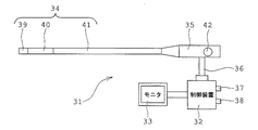
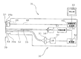
図7は本発明の実施例1にかかる照明光検出用光学系を備えた光学装置としての内視鏡装置の外観を概略的に示す説明図、図8は図7の内視鏡装置の内部の構成を概略的に示す説明図である。
Example 1
Next, specific examples of the optical apparatus including the illumination light detection optical system according to each of the above embodiments will be described.
FIG. 7 is an explanatory view schematically showing an appearance of an endoscope apparatus as an optical apparatus including the illumination light detection optical system according to the first embodiment of the present invention, and FIG. 8 is an internal view of the endoscope apparatus of FIG. It is explanatory drawing which shows the structure of no.
内視鏡装置31は、装置本体32と、内視鏡画像が表示されるモニタ33と、検査対象空間内に挿入される細長で可撓性を有する挿入部34と、挿入部34の挿入方向基端に接続された操作者により把持される操作部35と、操作部35から延出された可撓性を有するユニバーサルコード36を有して構成されている。装置本体32には、内視鏡装置31全体の電源スイッチであるメインスイッチ37と、装置本体32内に具備された光源のスイッチであるランプスイッチ38とが配設されている。
The
挿入部34には、挿入部34の先端側から順に、先端部39と、複数の湾曲駒が回動自在に連接されて形成された湾曲部40と、可撓性部材にて形成された長尺な可撓管部41とが連設されており、可撓管部41の基端部が、操作部35に接続されている。尚、湾曲部40は、操作部35の湾曲操作ノブ42の湾曲操作により、例えば上下/左右方向に湾曲される。
In the
先端部39の内部には、図8に示すように、検査対象空間内の観察像を結像するための対物光学系43と、対物光学系43により結像された検査対象空間内の観察像を電気信号である映像信号に変換するCCD等の撮像素子44と、照明光検出用光学系45と、検査対象空間内を照明する照明光を出射する蛍光部材46を備えている。
照明光検出用光学系45及び蛍光部材46は、夫々図1に示した第一実施形態の照明光検出用光学系10及び蛍光部材3とほぼ同様に構成されている。
蛍光部材3は、後述するLD47から出射された励起光と該励起光により励起された蛍光とが混成された光を照明光として出射する。
As shown in FIG. 8, an objective
The illumination light detection
The
撮像素子44には、映像信号線48が接続されている。映像信号線48は、装置本体32内に備えられている映像信号処理部49まで撮像素子44で変換された映像信号を伝送する。
映像信号処理部49は、伝送された映像信号をテレビ信号に変換し、内視鏡画像としてモニタ33に出力する。
A
The video
また、装置本体32内には、映像信号処理部49の他に、励起光を出射する光源となる発光素子、例えばレーザダイオード(LD)47と、LD47を駆動する制御を行う光源制御部であるLD制御部50と、LD47から出射された波長の短い励起光、例えば波長445nmの青色のレーザ光を集光させる集光光学系51とが備えられている。
In addition to the video
集光光学系51から出射されたレーザ光は、挿入部34及びユニバーサルコード36内において、一端が蛍光部材46に臨み他端が集光光学系51の焦点に臨むように配設された照明用ライトガイドである照明用光ファイバ52の他端に入射される。尚、照明用光ファイバ52は、1本の光ファイバで構成されている。
The laser light emitted from the condensing
照明用光ファイバ52の他端に入射されたレーザ光は、照明用光ファイバ52を通過して、照明用光ファイバ52の一端側に伝播され、その後、蛍光部材46に照射される。
The laser light incident on the other end of the illumination
蛍光部材46に含まれる蛍光体は、レーザ光を励起光として赤色光と緑色光の蛍光を出射する。蛍光は、蛍光部材46内で拡散された青色光と混成されて照明光となる白色光となって、前方に出射される。
The phosphor included in the
さらに、図8に示すように、装置本体32内には、LD制御部50に接続された光検出部54と、光検出部54に接続された光センサであるフォトダイオード(PD)53と、光検出用光ファイバ55の他端とPD53との間において、光検出用光ファイバ55の他端から出射される光の光路上に設けられた波長制限部材である光学フィルタ56が備えられている。
Furthermore, as shown in FIG. 8, in the apparatus
光学フィルタ56は、照明光検出用光学系45を介して抽出され、光検出用光ファイバ55を介して伝送された照明光の波長を制限して透過させ、透過後の光をPD53に検出させるフィルタ、具体的には、照明光検出用光学系45を介して抽出され、光検出用光ファイバ55を介して伝送された照明光から励起光である青色光を反射または吸収し、蛍光のみを透過させて、蛍光をPD53に検出させるフィルタである。
The
PD53は、光学フィルタ56を透過した蛍光を検出し、光検出部54は、PD53において検出された蛍光の強度を、後述するLD制御部30の駆動制御の下、検出するように構成されている。
The
蛍光部材46から出射され照明光検出用光学系45を介して偏向された照明光の戻り光は、挿入部34及びユニバーサルコード36内において、一端が照明光検出用光学系45に臨み他端がPD53に臨むように配設された光検出用ラィトガイドである光検出用光ファイバ55の一端に入射される。尚、光検出用光ファイバ55は、1本の光ファイバから構成されている。
The return light of the illumination light emitted from the
光検出用光ファイバ55の一端から入射された戻り光は、光検出用光ファイバ55を通過して、光検出用光ファイバ55の他端側に伝播され、光学フィルタ56に入射される。
The return light incident from one end of the light detection
その後、光学フィルタ56において、戻り光から蛍光のみが透過された後、該蛍光は、PD53に入射されて検出された後、さらに、制御部であるLD制御部50の駆動制御の下、光検出部54により、PD53により検出された蛍光の強度が検出され、該検出された強度から蛍光部材46の劣化がLD制御部50により検出される構成となっている。
Thereafter, after only the fluorescence is transmitted from the return light in the
次に、このように構成された実施例1の内視鏡装置の作用について説明する。先ず、メインスイッチ37がオンされると、内視鏡装置31全体の電源がオンされ、撮像素子44に結像された検査対象空間内の被写体の像が、映像信号処理部49においてテレビ信号に変換され、モニタ33に内視鏡画像として表示される。
Next, the operation of the endoscope apparatus of the first embodiment configured as described above will be described. First, when the
メインスイッチ37がオンされた状態で、ランプスイッチ38がオンされると、LD制御部50の駆動制御により、LD47が駆動され、LD47から出射された励起光である、例えば青色のレーザ光が、照明用光ファイバ52を介して蛍光部材46に入射される。
When the
その後、蛍光部材46から、青色のレーザ光を励起光として赤色光と緑色光の蛍光が出射され、該蛍光は、蛍光部材46内で拡散された青色光と混成されて照明光となる白色光となり、該白色光は、照明光学系45により、検査対象空間内に出射され、被写体が照明される。
Thereafter, red light and green light are emitted from the
この際、蛍光部材46から前方に出射された一部の光は、照明光学系45を介してPD53側に戻され、光検出用光ファイバ55を通過して、光学フィルタ56に入射される。その後、戻り光は、光学フィルタ56により、蛍光のみが透過され、該透過された蛍光が、PD53に入射される。即ち、PD53により蛍光が検出される。
At this time, part of the light emitted forward from the
その後、LD制御部50の駆動制御の下、光検出部54により、PD53において検出された蛍光の強度が検出され、該検出された強度から蛍光部材46の劣化がLD制御部50により検出される。
Thereafter, under the drive control of the
具体的には、光検出部54において、蛍光の強度が検出されない場合、または検出された蛍光の強度が、所定の値、詳しくは、検査空間対象内の検査に用いる通常の蛍光の強度よりも少なく、例えば、半分以下の強度が検出された場合、LD制御部50により、蛍光部材46は劣化している、と検出される。
Specifically, when the fluorescence intensity is not detected in the
その後、LD制御部50により、LD47からのレーザ光の出射の停止制御が行われ、LD47の駆動が停止される。尚、LD47の駆動を完全に停止させずに、LD47からレーザ光が出射しない出力で点灯するようにLD47を駆動制御してもよい。
Thereafter, the
実施例1の内視鏡装置によれば、照明光学系を第一実施形態の照明光検出光学系と同様に構成したので、光量ロスを極力少なく抑えながら、蛍光と励起光との混成比率が検査対象を照射する照明光と同じ比率の照明光を高精度に検出することができる。 According to the endoscope apparatus of Example 1, since the illumination optical system is configured in the same manner as the illumination light detection optical system of the first embodiment, the mixing ratio of fluorescence and excitation light is reduced while suppressing the light amount loss as much as possible. Illumination light having the same ratio as the illumination light that irradiates the inspection object can be detected with high accuracy.
また、実施例1の内視鏡装置は、装置本体32内の光検出用光ファイバ55の他端とPD53との間において、光検出用光ファイバ55の他端から出射される光の光路上に、照明光の戻り光から青色光を反射または吸収し、蛍光のみを透過させる光学フィルタ56を設けるとともに、光学フィルタ56により透過された蛍光を検出するPD53と、蛍光の強度を検出する光検出部54とを設け、さらに、蛍光部材46の劣化を検出するとともに、劣化の検出に基づき、LD47からのレーザ光の出射を停止させる駆動制御を行うLD制御部50を設けたので、蛍光部材46が劣化していたとしても、光検出用光ファイバ55、光学フィルタ56、PD53、光検出部54を介して、蛍光部材46の劣化を確実に検出することができる。このため、実施例1の内視鏡装置によれば、蛍光部材の劣化に伴う、蛍光の強度の低下または蛍光の未照射を確実に検出することができる。
In addition, the endoscope apparatus according to the first embodiment is on the optical path of light emitted from the other end of the optical fiber for
なお、本実施例においては、LD47から出射される励起光として、青色のレーザ光を用いたが、これに限らず、波長の短い励起光であれば、例えば紫外光を用いてもよい。この場合は、青色の蛍光も出射する蛍光体を用いることで白色光にすることができる。
In the present embodiment, blue laser light is used as the excitation light emitted from the
また、半導体発光素子は、LDに限定されず、低消費電力の半導体発光素子であれば、例えば発光ダイオード(LED)等であっても良い。 Further, the semiconductor light emitting element is not limited to the LD, and may be, for example, a light emitting diode (LED) as long as it is a semiconductor light emitting element with low power consumption.
また、本実施例においては、LD制御部50を、蛍光部材46の劣化を検出したときにLD47からのレーザ光の出射を停止させるように構成したが、これに加えて、LD制御部50を、蛍光部材46の劣化を検出したときに、警告音、警告表示等を発するように駆動制御して、使用者に対し、蛍光部材46の劣化を告知してもよい。
In the present embodiment, the
さらに、本実施例においては、LD制御部50は、蛍光部材46の劣化を検出するが、これに限らず、LD制御部50は、PD53により、蛍光の検出がなされない場合は、照明用光ファイバ52の破損も検出することができる。
Further, in the present embodiment, the
また、本実施例においては、ライトガイドである光検出用光ファイバ55、照明用光ファイバ52を、夫々1本の光ファイバで構成したが、これに限定されず、複数の光ファイバを束ねた光ファイババンドルで構成してもよい。
In this embodiment, the light detection
また、以下、別の変形例を、図9〜図11を用いて説明する。図9は図7の内視鏡装置の内部の構成の変形例を、挿入部の先端部のみ断面にして概略的に示す説明図、図10は図9の内視鏡装置の挿入部の先端部に着脱自在な光学アダプタを示す部分断面図、図11は図10の光学アダプタを図9の内視鏡装置の挿入部の先端部に装着した状態を示す部分断面図である。 Hereinafter, another modification will be described with reference to FIGS. FIG. 9 is an explanatory diagram schematically showing a modification of the internal configuration of the endoscope apparatus of FIG. 7 with only the distal end portion of the insertion section taken in cross section, and FIG. 10 is the distal end of the insertion section of the endoscope apparatus of FIG. FIG. 11 is a partial cross-sectional view showing a state where the optical adapter of FIG. 10 is attached to the distal end portion of the insertion portion of the endoscope apparatus of FIG. 9.
本変形例の内視鏡装置は、図9に示すように、先端部39の外周に、雄ねじ39aが形成されている。また、先端部39の外周であって雄ねじ39aよりも先端側に、位置決め溝39bが形成されている。尚、雄ねじ39aは、先端部39に光学アダプタ60を装着するためのネジである。
As shown in FIG. 9, the endoscope apparatus of this modification has a
先端部39の内部には、撮像素子44と、照明用光ファイバ52及び光検出用光ファイバ55の先端側が配置されており、撮像素子44は、撮像素子カバーガラス57により保護され、照明用光ファイバ52及び光検出用光ファイバ55の先端側は、光ファイバカバーガラス58により保護されている。
Inside the
図10に示すように、光学アダプタ60は、略円筒形状のアダプタ本体63と、略円柱形状の止め輪64と、抜け止め65とから主要部が構成されている。アダプタ本体63の内部には、撮像素子44に被写体の観察像を結像するための対物光学系43と、LD47からのレーザ光を励起光として蛍光を発する蛍光部材46と、蛍光部材46から出射される白色光である照明光を検査対象空間内に出射するとともに一部の光をPD53側に戻すための照明光検出用光学系45とが配置されている。照明光検出用光学系45及び蛍光部材46は、夫々図1に示した第一実施形態の照明光検出用光学系10及び蛍光部材3とほぼ同様に構成されている。
As shown in FIG. 10, the
アダプタ本体63の先端側外周には、雄ねじ63aが形成されている。雄ねじ63aは、抜け止め65の内周に形成された雌ねじ65aと螺合している。アダプタ本体63の挿入部側外周には、止め輪64と係合するための止め輪係合部63bが形成されている。
A
そして、止め輪係合部63bが止め輪64の先端側内周に形成されたアダプタ係合部64bと係合されることにより、止め輪64がアダプタ本体63に対し回転自在に構成されている。
Further, the retaining
また、抜け止め65の雌ねじ65aとアダプタ本体63の雄ねじ63aとの螺合部が接着固定されていることにより、止め輪64がアダプタ本体63から外れないように構成されている。
Further, the retaining
止め輪64の挿入部34側の内周には、雌ねじ64aが形成されている。雌ねじ64aは、先端部39の外周の雄ねじ39aと螺合することにより、光学アダプタ60が先端部39に装着される。
A
アダプタ本体63の挿入部34側の面には、位置決め突起63cが形成されている。位置決め突起63cは、光学アダプタ60が先端部39に装着された際、先端部39の位置決め溝39bと炭合することにより、アダプタ本体63の先端部39に対する回転を規制する。
A
これにより、光学アダプタ60が先端部39に装着された際、対物光学系43は撮像素子44に対向する位置に配置され、照明光検出用光学系45のPD53側出射面及び蛍光部材46は、光検出用光ファイバ55及び照明用光ファイバ52の先端側と対向する位置に夫々配置される。
Thereby, when the
図11に示すように、光学アダプタ60が、先端部39に装着された状態では、止め輪64の内周の雌ねじ64aと先端部39外周の雄ねじ39aとが螺合され、アダプタ本体63の位置決め突起63cと先端部39の位置決め溝39bとが螺合される。
As shown in FIG. 11, in a state where the
このように光学アダプタ60を先端部39に対し着脱自在に構成することで、光学アダプタ60の交換により、対物光学系43の特性を変更することができ、被写体に応じて視野角や観察方向、焦点深度が最適なものを選択することができる。尚、その他の構成は、図8の例と同様である。
By configuring the
光学アダプタ60が装着された状態では、LD47から出射された励起光であるレーザ光は、集光光学系51、照明用光ファイバ52、光ファイバカバーガラス58を通って、蛍光部材46に照射される。
In a state where the
蛍光部材46から前方に出射される照明光である白色光は、照明光検出用光学系45を介して検査対象空間内に出射されるとともに、一部の光がPD53側に戻される。戻り光は、光検出用光ファイバ55を通って、透過する光学フィルタ56で蛍光のみが抽出された後、PD53に検出され、その後、蛍光の強度が、LD制御部50の駆動制御の下、光検出部54により検出される。
White light, which is illumination light emitted forward from the
このように、蛍光部材46が光学アダプタ60に配設された構成では、先端部39から光学アダプタ60が取り外されると、蛍光部材46にLD47からレーザ光が照射されなくなるので照明光である白色光は出射されなくなることから、PD53において蛍光が検出されなくなる。
As described above, in the configuration in which the
よって、LD制御部50により、LD47からのレーザ光の出射が停止される駆動制御が行われることから、使用者は日玄しさを感じることなく光学アダプタ60を先端部39から着脱することができ、作業性が向上する。尚、この際、上述したように、LD47の駆動を完全に停止させずに、LD47からレーザ光が出射しない出力で点灯するようにlD47を駆動制御しても同様の効果を得ることができる。
Therefore, since the
また、光学アダプタ60を交換することにより、蛍光部材46を別の特性の蛍光部材に交換することができ、検査対象空間内を照明する光の波長を容易に変更することができる。このことから、使用者は、被写体に適した波長の照明を選択することができる。尚、その他の効果は、図8の例と同様である。
Moreover, by exchanging the
尚、光学アダプタ60の先端部39に対する着脱は、上述のようなねじの螺合に限定されず、ビス止めや凹凸係合によるロック構造等を用いてもよい。
The attachment / detachment of the
実施例2
図12は本発明の実施例2にかかる照明光検出用光学系を備えた光学装置としての内視鏡装置の内部の構成を概略的に示す説明図である。
実施例2の内視鏡装置は、図7、図8に示した内視鏡装置1と比べて、照明光の戻り光を、2つのPDで検出する点が異なる。ここでは、この相違点のみを説明し、実施例1と同様の構成には同じ符号を付し、その説明は省略する。
Example 2
FIG. 12 is an explanatory diagram schematically illustrating an internal configuration of an endoscope apparatus as an optical apparatus including the illumination light detection optical system according to the second embodiment of the present invention.
The endoscope apparatus according to the second embodiment is different from the
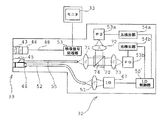
図12に示すように、装置本体31内には、光源制御部であるLD制御部50’に接続された光検出部54a,54bと、光検出部54aに接続されたフォトダイオード(PD)53aと、光検出部54bに接続されたフォトダイオード(PD)53bと、光検出用光ファイバ55の他端とPD53a,53bとの間に設けられた波長制限部材である光スプリッタ70が備えられている。
As shown in FIG. 12, in the apparatus
また、光スプリッタ70の入力端側、具体的には、光検出用光ファイバ55の他端に臨む位置には、集光光学系71が配置されている。また、光スプリッタ70の一方の出力端側には、集光光学系72が配置されている。また、光スプリッタ70の他方の出力端側には、集光光学系73が配置されている。集光光学系72の焦点付近には、PD53aが配置され、集光光学系73の焦点付近には、PD53bが配置されている。
Further, a condensing
集光光学系71は、光検知用光ファイバ55から出射された照明光の戻り光を集光して、光スプリッタ70に入射させる。集光光学系72は、光スプリッタ70から出射された蛍光を集光して、PD53aに入射させる。集光光学系73は、光スプリッタ70から出射された励起光を集光して、PD53bに入射させる。
The condensing
光スプリッタ70は、2個の直角プリズムの斜面同士を接合してキューブ型に構成されている。また、光スプリッタ70の一方のプリズムの斜面には、波長選択性のある反射薄膜74が蒸着されている。
The
反射薄膜74は、照明光の戻り光の内、励起光を透過し蛍光を反射する薄膜か、励起光を反射し蛍光を透過する薄膜かのいずれかにより構成されている。尚、以下の説明では、反射薄膜74は、励起光を透過し蛍光を反射する薄膜とする。この場合、PD53aは、蛍光のみを検出する第1の光センサとなり、PD53bは、励起光のみを検出する第2の光センサを構成する。
The reflective
このように構成された光スプリッタ70は、照明光の戻り光の波長を制限して透過と反射との少なくとも一方を行い、透過または反射後の励起光と蛍光とを、それぞれ別のPDにより検出させる。
The
具体的には、光スプリッタ70は、PD53bに向けて励起光である青色光を透過して、PD53bに青色光を検出させるとともに、PD53aに向けて蛍光を反射して、PD53aに蛍光を検出させる。
Specifically, the
光検出部54aは、PD53aにおいて検出された蛍光の強度を、LD制御部50'の駆動制御の下、検出する。光検出部54bは、PD53bにおいて検出された励起光の強度を、LD制御部50'の駆動制御の下、検出する。
The
LD制御部50’は、PD53aにおいて検出された蛍光の強度を、光検出部54aを駆動制御して検出するとともに、PD53bにおいて検出された励起光の強度を、光検出部54bを駆動制御して検出し、励起光の強度に対する蛍光の強度を検出することにより、蛍光部材46の劣化を検出する。
The
具体的には、光検出部54aにおいて、蛍光の強度が検出されない場合、または検出された励起光の強度に対する蛍光の強度が、所定の値、詳しくは、検査対象空間内の検査に用いる蛍光の強度よりも少なく、例えば、通常の半分以下の強度が検出された場合、LD制御部50’により、蛍光部材46は劣化している、と検出される。
Specifically, when the fluorescence intensity is not detected in the
その後、LD制御部50’により、LD47からのレーザ光の出射を停止する駆動制御が行われ、LD47の駆動が停止される。尚、LD47の駆動を完全に停止させずに、LD47からレーザ光が出射しない出力で点灯するようにLD47を駆動制御してもよい。
Thereafter, the
次に、このように構成された実施例2の内視鏡装置の作用を簡単に説明する。尚、実施例2においては、LD47によるレーザ光の出射から照明光の戻り光が光検出用光ファイバ55の他端から出射されるまでは、上述した実施例1と同様であるため、その説明は省略する。
Next, the operation of the endoscope apparatus of the second embodiment configured as described above will be briefly described. In the second embodiment, the process from the emission of the laser light by the
光検出用光ファイバ55の他端から出射された戻り光は、集光光学系71により集光されて、光スプリッタ70に入射される。その後、光スプリッタ70において、PD53bに向けて励起光である青色光が透過され、透過された青色光が集光光学系73により集光されて、PD53bに向けて出射され、PD53bに検知される。また、PD53aに向けて蛍光が反射され、反射された蛍光が集光光学系72により集光されて、PD53aに検知される。
The return light emitted from the other end of the optical fiber for
次いで、LD制御部50’の駆動制御の下、光検出部54aにより、蛍光の強度が検出されるともに、光検出部54bにより、青色光の強度が検出される。その後、LD制御部50’により、青色光の強度に対する蛍光の強度が検出される。これにより、蛍光部材46の劣化が検出される。そして、蛍光部材46の劣化が検出されると、LD制御部50’により、LD47からのレーザ光の出射が停止される制御が行われるか、LD47からレーザ光が出射しない出力で点灯するようにLD47を駆動する制御が行われる。
Next, under the drive control of the
このように、実施例2の内視鏡装置においては、光スプリッタ70により、戻り光から、蛍光と励起光とを分離して、それぞれ別個のPD53a,53bに蛍光と励起光とを検出させるとともに、LD制御部50’は、別個の光検出部54a,54bを駆動制御して、蛍光と励起光との強度をそれぞれ測定し、励起光の強度に対する蛍光の強度を検出することで、蛍光部材46の劣化を検出する。
As described above, in the endoscope apparatus according to the second embodiment, the
実施例2の内視鏡装置によれば、実施例1の内視鏡装置と同様、照明光学系を第一実施形態の照明光検出光学系と同様に構成したので、光量ロスを極力少なく抑えながら、蛍光と励起光との混成比率が検査対象を照射する照明光と同じ比率の照明光を高精度に検出することができる。 According to the endoscope apparatus of Example 2, since the illumination optical system is configured in the same manner as the illumination light detection optical system of the first embodiment, similarly to the endoscope apparatus of Example 1, the light amount loss is minimized. However, it is possible to detect with high accuracy the illumination light having a mixture ratio of fluorescence and excitation light that is the same as the illumination light that irradiates the inspection object.
また、実施例2の内視鏡装置によれば、蛍光の強度と励起光の強度との2つのパラメータを用いて、蛍光の強度の低下を検出するようにしたので、実施例1の内視鏡装置よりも、より精度良く、蛍光部材46の劣化を検出することができる。このため、実施例2の内視鏡装置によれば、蛍光部材の劣化に伴う、蛍光の強度の低下または蛍光の未照射をより確実に検出することができる。
Further, according to the endoscope apparatus of the second embodiment, the decrease in the fluorescence intensity is detected using the two parameters of the fluorescence intensity and the excitation light intensity. The deterioration of the
また、LD制御部50’は、PD53bにおいて検出された励起光の強度のみを、光検出部54bを駆動制御して検出することにより、照明用光ファイバ52またはLD47の破損を検知することができる。その際、LD制御部50’は、照明用光ファイバ52またはLD47の破損を検知後、LD47を完全に停止させる駆動制御を行う。
Further, the
尚、蛍光部材46の劣化と、照明用光ファイバ52またはLD47の破損との判断の切り分けは、上述したように、蛍光部材46の劣化検出後、LD47の駆動を完全に停止させずに、LD47からレーザ光が出射しない出力で点灯するようにLD47を駆動制御すれば、レーザ光が出射されていなくともLD47が駆動している場合は、使用者は蛍光部材46の劣化と判断でき、LD47の駆動が完全に停止している場合は、使用者は、照明用光ファイバ52またはLD47の破損と判断できる。
As described above, the determination of the deterioration of the
このように、実施例2の内視鏡装置では、蛍光部材46の劣化と、照明用光ファイバ52またはLD47の破損とを切り分けて検知することができる。
As described above, in the endoscope apparatus according to the second embodiment, the deterioration of the
尚、図12の例では、反射薄膜74として、励起光を透過し蛍光を反射する薄膜を用いたが、反射薄膜74には、励起光を反射し蛍光を透過する薄膜を用いてもよい。
In the example of FIG. 12, a thin film that transmits excitation light and reflects fluorescence is used as the reflective
その場合、集光光学系72は、光スプリッタ70から出射された励起光を集光して、PD53aに入射するものとなり、集光光学系73は、光スプリッタ70から出射された蛍光を集光して、PD53bに入射するものとなる。また、PD53aは、励起光のみを検出する第2の光センサとなり、PD53bは、蛍光のみを検出する第1の光センサとなる。
In that case, the condensing
よって、光スプリッタ70は、PD53bに向けて蛍光を透過して、PD53bに蛍光を検出させるとともに、PD53aに向けて励起光を反射して、PD53aに励起光を検出させる。
Therefore, the
また、光検出部54bは、PD53aにおいて検出された励起光の強度を、LD制御部50’の制御の下、検出するものとなり、光検出部54bは、PD53bにおいて検出された蛍光の強度を、LD制御部50’の駆動制御の下、検出するものとなる。
The
また、実施例2においても、波長の短い励起光としては、青色のレーザ光に限定されずに、例えば紫外光を用いてもよい。半導体発光素子は、LDに限定されず、低消費電力の半導体発光素子であれば、例えば発光ダイオード(LED)等でもよい。 Also in the second embodiment, the excitation light having a short wavelength is not limited to the blue laser light, and for example, ultraviolet light may be used. The semiconductor light emitting element is not limited to the LD, and may be, for example, a light emitting diode (LED) as long as it is a semiconductor light emitting element with low power consumption.
さらに、LD制御部50’は、蛍光部材46の劣化を検出した後、警告音や警告表示等を発する駆動制御を行うことにより、使用者に対し、蛍光部材46の劣化を告知してもよい。
Further, the
さらに、実施例2の内視鏡装置においても、図9〜図11に示した実施例1の変形例と同様に、挿入部34の先端部39に対し、光学アダプタ60が着脱自在な構成としてもよい。尚、この場合の効果は、図9〜図11に示した変形例とほぼ同じである。
Further, also in the endoscope apparatus of the second embodiment, the
実施例3
図13は本発明の実施例3にかかる照明光検出用光学系を備えた光学装置としての内視鏡装置の内部の構成を概略的に示す説明図である。
実施例3の内視鏡装置は、図11に示した内視鏡装置と比べて、光スプリッタを、入射される戻り光に対し、波長の制限を行わず、戻り光を2方向に分割する、単なるハーフミラーで構成した点が異なる。ここでは、この相違点のみを説明し、実施例1、実施例2と同様の構成には同じ符号を付し、その説明は省略する。
Example 3
FIG. 13 is an explanatory diagram schematically illustrating an internal configuration of an endoscope apparatus as an optical apparatus including the illumination light detection optical system according to the third embodiment of the present invention.
Compared with the endoscope apparatus shown in FIG. 11, the endoscope apparatus according to the third embodiment divides the return light into two directions without limiting the wavelength of the incident return light. The difference is that it consists of a simple half mirror. Here, only this difference is demonstrated, the same code | symbol is attached | subjected to the structure similar to Example 1 and Example 2, and the description is abbreviate | omitted.
図13に示すように、装置本体32内には、光源制御部であるLD制御部50”に接続された光検出部54a,54bと、光検出部54aに接続されたPD53aと、光検出部54bに接続されたPD53bと、波長制限部材である第1の光学フィルタ75と、波長制限部材である第2の光学フィルタ76と、光スプリッタ70’が備えられている。
As shown in FIG. 13, in the apparatus
また、光スプリッタ70’の入力端側、具体的には、光検出用光ファイバ55の他端に臨む位置には、集光光学系71が配置されている。また、光スプリッタ70’の一方の出力端側には、集光光学系72が配置されている。また、光スプリッタ70’の他方の出力端側には、集光光学系73が配置されている。
Further, a condensing
また、集光光学系72の焦点付近であって、集光光学系72とPD53aとの間には、第1の光学フィルタ75が配置され、集光光学系73の焦点付近であって、集光光学系73とPD53bとの間には、第2の光学フィルタ76が配置されている。
In addition, a first
集光光学系71は、光検知用光ファイバ55の他端から出射された照明光の戻り光を集光して、光スプリッタ70’に入射させる。集光光学系72は、光スプリッタ70’から出射された戻り光を集光して、第1の光学フィルタ75に入射させる。集光光学系73は、光スプリッタ70’から出射された戻り光を集光して、第2の光学フィルタ76に入射させる。
The condensing
光スプリッタ70’は、2個の直角プリズムの斜面同士を接合してキューブ型に構成されている。また、光スプリッタ70’は、一方のプリズムの斜面に、入射された照明光の戻り光をPD53aとPD53bに向けてそれぞれ分割する、単なるハーフミラーとして機能する反射薄膜74’が蒸着されている。
The optical splitter 70 'is formed in a cube shape by joining the inclined surfaces of two right-angle prisms. The
PD53aは、蛍光のみを検出する第1の光センサであり、PD53bは、励起光のみを検出する第2の光センサである。
The
また、第1の光学フィルタ75は、光スプリッタ70’により分割された照明光の戻り光の波長を制限して透過させ、PD53aに、透過後の戻り光を検出させるフィルタ、具体的には、蛍光のみを透過させ、PD53aに、透過後の蛍光を検出させるフィルタである。
The first
第2の光学フィルタ76は、光スプリッタ70’により分割された照明光の戻り光の波長を制限して透過させ、PD53bに、透過後の戻り光を検出させるフィルタ、具体的には、励起光である青色光のみを透過させ、PD53bに、透過後の青色光を検出させるフィルタである。
The second
光検出部54aは、PD53aにおいて検出された蛍光の強度を、LD制御部50”の駆動制御の下、検出する。光検出部54bは、PD53bにおいて検出された励起光の強度を、LD制御部50”の駆動制御の下、検出する。
The
LD制御部50”は、PD53aにおいて検出された蛍光の強度を、光検出部54aを用いて検出するとともに、PD53bにおいて検出された励起光の強度を、光検出部54bを用いて検出し、励起光の強度に対する蛍光の強度を検出することにより、蛍光部材46の劣化を検出する。
The
具体的には、光検出部54aにおいて、蛍光の強度が検出されない場合、または検出された励起光の強度に対する蛍光の強度が、所定の値、詳しくは、検査対象空間内の検査に用いる蛍光の強度よりも少なく、例えば、通常の半分以下の強度が検出された場合、LD制御部50”により、蛍光部材46は劣化している、と検出される。
Specifically, when the fluorescence intensity is not detected in the
その後、LD制御部50”により、LD47からのレーザ光の出射を停止する駆動制御が行われ、LD47の駆動が停止される。尚、LD47の駆動を完全に停止させずに、LD47からレーザ光が出射しない出力で点灯するようにLD47を駆動制御してもよい。
Thereafter, the
次に、このように構成された実施例3の内視鏡装置の作用を簡単に説明する。尚、実施例3においても、LD47によるレーザ光の出射から照明光の戻り光が光検出用光ファイバ55の他端から出射されるまでは、上述した実施例1と同様であるため、その説明は省略する。
Next, the operation of the endoscope apparatus of the third embodiment configured as described above will be briefly described. In the third embodiment, since the laser beam is emitted from the
光検出用光ファイバ55の他端から出射された戻り光は、集光光学系71により集光されて、光スプリッタ70’に入射される。その後、光スプリッタ70’において、PD53a,53bに向けて戻り光が分割され、一方の戻り光が集光光学系72により集光されて、PD53aに向けて出射され、第1の光学フィルタ75により、蛍光のみが透過された後、蛍光のみが、PD53aに検知される。
The return light emitted from the other end of the optical fiber for
また、他方の戻り光が、集光光学系73により集光されて、PD53bに向けて出射され、第2の光学フィルタ76により、励起光のみが透過された後、励起光のみが、PD53bに検知される。
The other return light is condensed by the condensing
次いで、LD制御部50”の駆動制御の下、光検出部54aにより、蛍光の強度が検出されるともに、光検出部54bにより、励起光の強度が検出される。その後、LD制御部50”により、励起光の強度に対する蛍光の強度が検出される。これにより、蛍光部材46の劣化が検出される。そして、蛍光部材46の劣化が検出されると、LD制御部50”により、LD47からのレーザ光の出射が停止される制御が行われるか、LD47からレーザ光が出射しない出力で点灯するようにLD47を駆動する制御が行われる。
Next, under the drive control of the
実施例3の内視鏡装置によれば、実施例1の内視鏡装置と同様、照明光学系を第一実施形態の照明光検出光学系と同様に構成したので、光量ロスを極力少なく抑えながら、蛍光と励起光との混成比率が検査対象を照射する照明光と同じ比率の照明光を高精度に検出することができる。 According to the endoscope apparatus of Example 3, as with the endoscope apparatus of Example 1, the illumination optical system is configured in the same manner as the illumination light detection optical system of the first embodiment, so that the light amount loss is minimized. However, it is possible to detect with high accuracy the illumination light having a mixture ratio of fluorescence and excitation light that is the same as the illumination light that irradiates the inspection object.
また、実施例3の内視鏡装置においても、LD制御部50”は、PD53bにおいて検出された励起光の強度のみを、光検出部54bを用いて検出することにより、照明用光ファイバ52またはLD47の破損を検知することができる。その際、LD制御部50”は、照明用光ファイバ52またはLD47の破損を検知後、LD47を完全に停止させる駆動制御を行う。
Also in the endoscope apparatus of the third embodiment, the
尚、蛍光部材46の劣化と、照明用光ファイバ52またはLD47の破損との判断の切り分けは、上述したように、蛍光部材46の劣化検出後、LD47の駆動を完全に停止させずに、LD47からレーザ光が出射しない出力で点灯するようにLD47を駆動制御すれば、レーザ光が出射されていなくともLD47が駆動している場合は、使用者は蛍光部材46の劣化と判断でき、LD47の駆動が完全に停止している場合は、使用者は、照明用光ファイバ52またはLD47の破損と判断できる。
As described above, the determination of the deterioration of the
このように、実施例3の内視鏡装置においても、蛍光部材46の劣化と、照明用光ファイバ52またはLD47の破損とを切り分けて検知することができる。
As described above, also in the endoscope apparatus according to the third embodiment, the deterioration of the
尚、実施例3の内視鏡装置においても、波長の短い励起光としては、青色のレーザ光に限定されずに、例えば紫外光を用いてもよい。また、半導体発光素子は、LDに限定されず、低消費電力の半導体発光素子であれば、例えば発光ダイオード(LED)等でもよい。 In the endoscope apparatus according to the third embodiment, the excitation light having a short wavelength is not limited to the blue laser light, and for example, ultraviolet light may be used. Further, the semiconductor light emitting element is not limited to the LD, and may be, for example, a light emitting diode (LED) as long as it is a semiconductor light emitting element with low power consumption.
さらに、LD制御部50”は、蛍光部材46の劣化を検出した後、警告音や警告表示等を発する駆動制御を行うことにより、使用者に対し、蛍光部材46の劣化を告知してもよい。
Further, the
さらに、実施例3の内視鏡装置においても、図9〜図11に示した実施例1の変形例と同様に、挿入部34の先端部39に対し、光学アダプタ60が着脱自在な構成としてもよい。尚、この場合の効果は、図9〜図11に示した変形例とほぼ同じである。
Furthermore, also in the endoscope apparatus of the third embodiment, the
実施例4
図14は本発明の実施例4にかかる照明光検出用光学系を備えた光学装置としての内視鏡装置の内部の構成を概略的に示す説明図である。
実施例4の内視鏡装置は、図7、図8に示した内視鏡装置と比べて、照明光の戻り光を、青、緑、赤にそれぞれ感度を持つようにしたカラーフィルタを組み合わせた3チャンネルのPDを1つにパッケージしたRGBカラーセンサにおいて、緑、赤色の蛍光と青色の励起光とに分けて透過させる点が異なる。ここでは、この相違点のみを説明し、実施例1と同様の構成には同じ符号を付し、その説明は省略する。
Example 4
FIG. 14 is an explanatory diagram schematically illustrating an internal configuration of an endoscope apparatus as an optical apparatus including the illumination light detection optical system according to the fourth embodiment of the present invention.
The endoscope apparatus according to the fourth embodiment is combined with a color filter in which the return light of the illumination light has sensitivity to blue, green, and red, respectively, as compared with the endoscope apparatus illustrated in FIGS. In the RGB color sensor in which three-channel PDs are packaged in one, green and red fluorescence and blue excitation light are transmitted separately. Here, only this difference will be described, the same reference numerals are given to the same components as those in the first embodiment, and the description thereof will be omitted.
図14に示すように、装置本体32内には、光源制御部であるLD制御部50”’に接続された光検出部54と、光検出部54に接続された光センサであるRGBカラーセンサ80が備えられている。
As shown in FIG. 14, in the apparatus
RGBカラーセンサ80は、照明光の戻り光を、青色、緑色、赤色にそれぞれ感度を持つようにしたカラーフィルタ81R、81G、81Bを組み合わせた3チャンネルのPDを1つにパッケージしたカラーセンサである。
The
赤色カラーフィルタ81R、緑色カラーフィルタ81Gは、照明光の戻り光の波長を制限して透過させ、透過後の戻り光をRGBカラーセンサ80に検出させるフィルタであり、具体的には、戻り光から青色の励起光を反射または吸収し、それぞれ、赤色、緑色の蛍光のみを透過させて、蛍光をRGBカラーセンサ80に検出させる第1の波長制限部材である。
The
青色カラーフィルタ81Bは、照明光の戻り光の波長を制限して透過させ、透過後の戻り光をRGBカラーセンサ80に検出させるフィルタであり、具体的には、戻り光から赤色及び緑色の蛍光を反射または吸収し、青色の励起光のみを透過させて、青色の励起光をRGBカラーセンサ80に検出させる第2の波長制限部材である。
The
光検出部54は、RGBカラーセンサ80において検出された蛍光の強度及び励起光の強度を、LD制御部50”’の駆動制御の下、検出する。
The
LD制御部50”’は、カラーフィルタ80において検出された蛍光及び励起光の強度を、光検出部54を用いて検出し、励起光の強度に対する蛍光の強度を検出することにより、蛍光部材46の劣化を検出する。
The
具体的には、RGBカラーセンサ80において、蛍光の強度が検出されない場合、または検出された励起光の強度に対する蛍光の強度が、所定の値、詳しくは、検査対象空間内の検査に用いる蛍光の強度よりも低く、例えば通常の半分以下の強度が検出された場合、LD制御部50”’により、蛍光部材46は劣化している、と検出される。
Specifically, when the intensity of the fluorescence is not detected in the
その後、LD制御部50”’により、LD47からのレーザ光の出射が停止される駆動制御が行われる。具体的には、LD47の駆動が停止される。尚、LD47の駆動を完全に停止させずに、LD47からレーザ光が出射しない出力で点灯するようにLD47を駆動制御してもよい。
Thereafter, the
次に、このように構成された実施例4の内視鏡装置の作用を簡単に説明する。尚、実施例4においても、LD47によるレーザ光の出射から照明光の戻り光が光検出用光ファイバ55の他端から出射されるまでは、上述した実施例1と同様であるため、その説明は省略する。
Next, the operation of the endoscope apparatus of the fourth embodiment configured as described above will be briefly described. In the fourth embodiment, the process from the emission of the laser light by the
光検出用光ファイバ55の他端から出射された戻り光は、RGBカラーフィルタ80に出射され、RGBカラーフィルタ80において、赤色カラーフィルタ81R、緑色カラーフィルタ80Gを介して、戻り光から赤色、緑色の蛍光のみをそれぞれのフィルタで透過させて、蛍光をRGBカラーセンサ80に検出させるとともに、青色カラーフィルタ81Bを介して、戻り光から青色の励起光のみを透過させて、励起光をRGBカラーセンサ80に検出させる。
The return light emitted from the other end of the optical fiber for
次いで、LD制御部50”’の駆動制御の下、光検出部54により、蛍光の強度及び励起光の強度が検出される。その後、LD制御部50”’により、励起光の強度に対する蛍光の強度が検出される。これにより、蛍光部材46の劣化が検出される。そして、蛍光部材46の劣化が検出されると、LD制御部50”’により、LD47からのレーザ光の出射が停止される制御が行われるか、LD47からレーザ光が出射しない出力で点灯するようにLD47を駆動する制御が行われる。
Next, under the drive control of the
実施例4の内視鏡装置によれば、実施例1の内視鏡装置と同様、照明光学系を第一実施形態の照明光検出光学系と同様に構成したので、光量ロスを極力少なく抑えながら、蛍光と励起光との混成比率が検査対象を照射する照明光と同じ比率の照明光を高精度に検出することができる。 According to the endoscope apparatus of Example 4, like the endoscope apparatus of Example 1, the illumination optical system is configured in the same manner as the illumination light detection optical system of the first embodiment, so that the light amount loss is minimized. However, it is possible to detect with high accuracy the illumination light having a mixture ratio of fluorescence and excitation light that is the same as the illumination light that irradiates the inspection object.
また、実施例4の内視鏡装置においても、LD制御部50”’は、RGBカラーセンサ80において検出された青色の励起光の強度のみを、光検出部54を用いて検出することにより、照明用光ファイバ55またはLD47の破損を検知することができる。その際、LD制御部50”’は、照明用光ファイバ55またはLD47の破損を検知後、LD47を完全に停止させる駆動制御を行う。
Also in the endoscope apparatus of the fourth embodiment, the
尚、蛍光部材46の劣化と、照明用光ファイバ52またはLD47の破損との判断の切り分けは、上述したように、蛍光部材46の劣化検出後、LD47の駆動を完全に停止させずに、LD47からレーザ光が出射しない出力で点灯するようにLD47を駆動制御すれば、レーザ光が出射されていなくともLD47が駆動している場合は、使用者は蛍光部材46の劣化と判断でき、LD47の駆動が完全に停止している場合は、使用者は、照明用光ファイバ52またはLD47の破損と判断できる。
As described above, the determination of the deterioration of the
このように、実施例4の内視鏡装置においても、LD制御部50”’は、蛍光部材46の劣化と、照明用光ファイバ52またはLD47の破損とを切り分けて検知することができる。
As described above, also in the endoscope apparatus according to the fourth embodiment, the
尚、実施例4の内視鏡装置においても、LD制御部50”’は、蛍光部材46の劣化を検出した後、警告音や警告表示等を発する駆動制御を行うことにより、使用者に対し、蛍光部材46の劣化を告知してもよい。
Also in the endoscope apparatus of the fourth embodiment, the
さらに、実施例4の内視鏡装置においても、図9〜図11に示した実施例1の変形例と同様に、挿入部34の先端部39に対し、光学アダプタ60が着脱自在な構成としてもよい。尚、この場合の効果は、図9〜図11に示した変形例とほぼ同じである。
Furthermore, also in the endoscope apparatus according to the fourth embodiment, the
また、上述した実施例1〜実施例4においては、内視鏡装置は、工業用の内視鏡装置を例に挙げて示したが、工業用の内視鏡装置に限定されず、医療用の内視鏡装置に適用可能である。 Further, in the above-described first to fourth embodiments, the endoscope apparatus has been described using an industrial endoscope apparatus as an example, but is not limited to an industrial endoscope apparatus, and is used for medical purposes. The present invention can be applied to other endoscope apparatuses.
本発明の照明光検出用光学系並びにそれを備えた光学装置及び内視鏡装置は、極細化した径でもって観察対象に照射しながら観察することが求められる医療や工業の分野に有用である。 INDUSTRIAL APPLICABILITY The illumination light detection optical system of the present invention and the optical apparatus and endoscope apparatus provided with the optical system are useful in medical and industrial fields that require observation while irradiating an observation target with an extremely thin diameter. .
1 発光素子
2 挿入部
3,3’ 蛍光部材
3a 反射面
3b’ 出射面
4 励起光導光手段
4a ファイバー(コア+クラッド)
4b 保持部材
5 光検出手段
5a 検出用照明光導光手段
5b 光検出部
5b1,5b2 受光素子
5c ダイクロイックミラー
5d 演算装置
10 照明光検出用光学系
11 照明光照射用柱状透明部材
11a 側面
11a1 接合面
11b 先端面
12 照明光抽出手段
13 偏向手段
14 透明媒体
15,15’ 照明光抽出用柱状透明部材
15a,15a’ 側面
15a1,15a1’ 接合面
15b,15b1’,15b2’ 傾斜面
15c,15c1’,15c2’ 反射膜
15d’ 端面
16 接着剤
17 ボールレンズアレイ
18 光拡散手段
19 透明部材
19a 一端面
19b 出射面
20 ボールレンズアレイ
21 接着剤
31 内視鏡装置
32 装置本体
33 モニタ
34 挿入部
35 操作部
36 ユニバーサルコード
37 メインスイッチ
38 ランプスイッチ
39 先端部
39a 雄ねじ
39b 位置決め溝
40 湾曲部
41 可撓管部
42 湾曲操作ノブ
43 対物光学系
44 撮像素子
45 照明光検出用光学系
46 蛍光部材
47 LD(レーザダイオード)
48 映像信号機
49 映像信号処理部
50,50’,50”,50”’ LD制御部
51 集光光学系
52 照明用光ファイバ
53,53a,53b PD(フォトダイオード)
54,54a,54b 光検出部
55 光検出用光ファイバ
56 光学フィルタ
57 撮像素子カバーガラス
58 光ファイバカバーガラス
60 光学アダプタ
63 アダプタ本体
63a 雄ねじ
63b 止め輪係合部
63c 位置決め突起
64 止め輪
64a 雌ねじ
64b アダプタ係合部
65 抜け止め
65a 雌ねじ
70,70’ 光スプリッタ
71,72,73 集光光学系
74 反射薄膜
75,76 光学フィルタ
80 RGBカラーセンサ
81R,81G,81B カラーフィルタ
151 受光部材
151a 側面
151b 端面
152,152’ 光センサ
153 照明用光源
154,155,155’ 導光手段
156 通信線
DESCRIPTION OF
48
54, 54a,
Claims (13)
前記蛍光部材から出射された照明光の一部を抽出する照明光検出用光学系と、該照明光検出用光学系により抽出された照明光を検出する光検出手段とをさらに有しており、
前記照明光検出用光学系が、前記蛍光部材の前方に同軸配置された照明光照射用柱状透明部材と、前記蛍光部材から前方に出射して前記照明光照射用柱状透明部材の内部に入る照明光のうち前記照明光照射用柱状透明部材の側面に対して全反射角よりも小さい角度で入射する照明光を該照明光照射用柱状透明部材から抽出する照明光抽出手段と、前記抽出した照明光を前記光検出手段に向ける偏向手段とを有し、
前記照明光抽出手段が、前記照明光照射用柱状透明部材よりも小さい屈折率を有し、かつ、接合作用を有する透明媒体と、該照明光照射用柱状透明部材と同じ屈折率を有する照明光抽出用柱状透明部材とからなり、前記透明媒体を介して前記照明光抽出用柱状透明部材の側面を、該照明光照射用柱状透明部材の側面に接合して構成され、
前記透明媒体が、接着剤と、ボールレンズとからなること、を特徴とする光学装置。 A light emitting element that emits excitation light, an elongated insertion part, a fluorescent member disposed near the tip of the insertion part, and an excitation light guiding unit that guides the excitation light emitted from the light emitting element to the fluorescent member. An optical device comprising:
Further comprising an illumination light detection optical system for extracting a part of the illumination light emitted from the fluorescent member, and a light detection means for detecting the illumination light extracted by the illumination light detection optical system,
Illumination light irradiation columnar transparent member coaxially disposed in front of the fluorescent member, and illumination light emitted forward from the fluorescent member and entering the illumination light irradiation columnar transparent member. Illumination light extraction means for extracting illumination light incident on a side surface of the illumination light irradiation columnar transparent member out of light at an angle smaller than a total reflection angle from the illumination light irradiation columnar transparent member, and the extracted illumination Deflection means for directing light toward the light detection means ,
The illumination light extraction means has a refractive index smaller than that of the columnar transparent member for illumination light irradiation and has a bonding action, and illumination light having the same refractive index as that of the columnar transparent member for illumination light irradiation It consists of a columnar transparent member for extraction, and the side surface of the columnar transparent member for extraction of illumination light is joined to the side surface of the columnar transparent member for illumination light irradiation via the transparent medium,
Optical device wherein the transparent medium, characterized with the adhesive, the Rukoto, such a ball lens.
前記蛍光部材から出射された照明光の一部を抽出する照明光検出用光学系と、前記蛍光部材の前方に配置されている照明光照射用柱状透明部材と、前記照明光検出用光学系により抽出された照明光を検出する光検出手段とを更に有しており、
前記照明光検出用光学系が、前記蛍光部材に面していてその一部の領域が前記蛍光部材の出射面の極く一部の領域に重なっている端面を有しており且つ該蛍光部材から前方に出射した照明光のうち前記蛍光部材の出射面の一部の領域から出射した光を前記端面の一部の領域を介して抽出するように配置された照明光抽出用柱状透明部材からなる照明光抽出手段と、前記抽出した照明光を前記光検出手段に向ける偏向手段とを有していること、を特徴とする光学装置。 A light emitting element that emits excitation light, an elongated insertion part, a fluorescent member disposed near the tip of the insertion part, and an excitation light guiding means that guides the excitation light emitted from the light emitting element to the fluorescent member; An optical device comprising:
An illumination light detection optical system for extracting a part of the illumination light emitted from the fluorescent member, an illumination light irradiation columnar transparent member disposed in front of the fluorescent member, and the illumination light detection optical system A light detecting means for detecting the extracted illumination light;
The illumination light detection optical system has an end face that faces the fluorescent member and a part of the optical system overlaps with a part of the emission surface of the fluorescent member, and the fluorescent member From the illumination light extraction columnar transparent member arranged to extract the light emitted from the partial area of the emission surface of the fluorescent member out of the illumination light emitted forward from the illumination light extraction column An optical apparatus comprising: an illumination light extraction unit that is configured to be a deflecting unit that directs the extracted illumination light toward the light detection unit.
前記蛍光部材から出射された照明光の一部を抽出する照明光検出用光学系と、該照明光検出用光学系により抽出された照明光を検出する光検出手段とをさらに有しており、
前記照明光検出用光学系が、前記蛍光部材の前方に同軸配置された照明光照射用柱状透明部材と、前記蛍光部材から前方に出射して前記照明光照射用柱状透明部材の内部に入る照明光のうち前記照明光照射用柱状透明部材の側面に対して全反射角よりも小さい角度で入射する照明光を該照明光照射用柱状透明部材から抽出する照明光抽出手段と、
前記抽出した照明光を前記光検出手段に向ける偏向手段とを有し、
前記偏向手段が、前記照明光抽出用柱状透明部材の先端に形成された傾斜面と該傾斜面に設けた反射膜とからなる反射面で構成されていることを特徴とする光学装置。 A light emitting element that emits excitation light, an elongated insertion part, a fluorescent member disposed near the tip of the insertion part, and an excitation light guiding unit that guides the excitation light emitted from the light emitting element to the fluorescent member. An optical device comprising:
Further comprising an illumination light detection optical system for extracting a part of the illumination light emitted from the fluorescent member, and a light detection means for detecting the illumination light extracted by the illumination light detection optical system,
Illumination light irradiation columnar transparent member coaxially disposed in front of the fluorescent member, and illumination light emitted forward from the fluorescent member and entering the illumination light irradiation columnar transparent member. Illumination light extraction means for extracting illumination light incident at an angle smaller than the total reflection angle with respect to the side surface of the illumination light irradiation columnar transparent member of light from the illumination light irradiation columnar transparent member;
Deflection means for directing the extracted illumination light toward the light detection means,
The deflection means, the optical science device you characterized in that it is constituted by a reflecting surface comprising a reflective film provided on the inclined surface and the inclined surface formed at the tip of the illumination light extraction columnar transparent members.
前記蛍光部材から出射された照明光の一部を抽出する照明光検出用光学系と、該照明光検出用光学系により抽出された照明光を検出する光検出手段とをさらに有しており、
前記照明光検出用光学系が、前記蛍光部材の前方に同軸配置された照明光照射用柱状透明部材と、前記蛍光部材から前方に出射して前記照明光照射用柱状透明部材の内部に入る照明光のうち前記照明光照射用柱状透明部材の側面に対して全反射角よりも小さい角度で入射する照明光を該照明光照射用柱状透明部材から抽出する照明光抽出手段と、前記抽出した照明光を前記光検出手段に向ける偏向手段とを有し、
前記偏向手段が、前記照明光抽出用柱状透明部材の先端に形成された2つの傾斜面と該2つの傾斜面に設けた反射膜とからなる2つの反射面で構成されていることを特徴とする光学装置。 A light emitting element that emits excitation light, an elongated insertion part, a fluorescent member disposed near the tip of the insertion part, and an excitation light guiding unit that guides the excitation light emitted from the light emitting element to the fluorescent member. An optical device comprising:
Further comprising an illumination light detection optical system for extracting a part of the illumination light emitted from the fluorescent member, and a light detection means for detecting the illumination light extracted by the illumination light detection optical system,
Illumination light irradiation columnar transparent member coaxially disposed in front of the fluorescent member, and illumination light emitted forward from the fluorescent member and entering the illumination light irradiation columnar transparent member. Illumination light extraction means for extracting illumination light incident on a side surface of the illumination light irradiation columnar transparent member out of light at an angle smaller than a total reflection angle from the illumination light irradiation columnar transparent member, and the extracted illumination Deflection means for directing light toward the light detection means,
The deflecting means is composed of two reflecting surfaces composed of two inclined surfaces formed at the tip of the illumination light extracting columnar transparent member and a reflecting film provided on the two inclined surfaces. It is that light science equipment.
前記蛍光部材から出射された照明光の一部を抽出する照明光検出用光学系と、前記蛍光部材の前方に配置されている照明光照射用柱状透明部材と、前記照明光検出用光学系により抽出された照明光を検出する光検出手段とを更に有しており、An illumination light detection optical system for extracting a part of the illumination light emitted from the fluorescent member, an illumination light irradiation columnar transparent member disposed in front of the fluorescent member, and the illumination light detection optical system A light detecting means for detecting the extracted illumination light;
前記照明光検出用光学系が、前記蛍光部材に面していてその一部の領域が前記蛍光部材の出射面の極く一部の領域に重なっている端面を有しており且つ該蛍光部材から前方に出射した照明光のうち前記蛍光部材の出射面の一部の領域から出射した光を前記端面の一部の領域を介して抽出するように配置された照明光抽出用柱状透明部材からなる照明光抽出手段と、前記抽出した照明光を前記光検出手段に向ける偏向手段とを有し、The illumination light detection optical system has an end face that faces the fluorescent member and a part of the optical system overlaps with a part of the emission surface of the fluorescent member, and the fluorescent member From the illumination light extraction columnar transparent member arranged to extract the light emitted from the partial area of the emission surface of the fluorescent member out of the illumination light emitted forward from the illumination light extraction column Illumination light extraction means, and deflection means for directing the extracted illumination light toward the light detection means,
前記偏向手段が、前記照明光抽出用柱状透明部材の先端に形成された傾斜面と該傾斜面に設けた反射膜とからなる反射面で構成されていることを特徴とする光学装置。An optical apparatus, wherein the deflecting unit is configured by a reflecting surface including an inclined surface formed at a tip of the illumination light extracting columnar transparent member and a reflecting film provided on the inclined surface.
前記蛍光部材から出射された照明光の一部を抽出する照明光検出用光学系と、該照明光検出用光学系により抽出された照明光を検出する光検出手段とをさらに有しており、Further comprising an illumination light detection optical system for extracting a part of the illumination light emitted from the fluorescent member, and a light detection means for detecting the illumination light extracted by the illumination light detection optical system,
前記照明光検出用光学系が、前記蛍光部材の前方に同軸配置された照明光照射用柱状透明部材と、前記蛍光部材から前方に出射して前記照明光照射用柱状透明部材の内部に入る照明光のうち前記照明光照射用柱状透明部材の側面に対して全反射角よりも小さい角度で入射する照明光を該照明光照射用柱状透明部材から抽出する照明光抽出手段と、前記抽出した照明光を前記光検出手段に向ける偏向手段とを有し、Illumination light irradiation columnar transparent member coaxially disposed in front of the fluorescent member, and illumination light emitted forward from the fluorescent member and entering the illumination light irradiation columnar transparent member. Illumination light extraction means for extracting illumination light incident on a side surface of the illumination light irradiation columnar transparent member out of light at an angle smaller than a total reflection angle from the illumination light irradiation columnar transparent member, and the extracted illumination Deflection means for directing light toward the light detection means,
前記照明光照射用柱状透明部材の先端面に光拡散手段をさらに備え、A light diffusing means is further provided on the front end surface of the columnar transparent member for illumination light irradiation;
前記光拡散手段が、前記照明光照射用柱状透明部材の先端面と、該照明光照射用柱状透明部材と同じ屈折率を持つ透明部材の一端面とを、異なる屈折率のボールレンズアレイ及び接着剤を挟んで接合してなることを特徴とする光学装置。The light diffusing means attaches the front end surface of the illumination light irradiation columnar transparent member and the one end surface of the transparent member having the same refractive index as the illumination light irradiation columnar transparent member and a ball lens array having different refractive indexes and adhesion An optical device characterized by being bonded with an agent interposed therebetween.
前記照明光検出用光学系を介して得られた光を励起光成分と蛍光成分とに分光する分光部材と、
分光された夫々の光を受光する受光素子と、
該夫々の受光素子で受光した光量の比率を算出する演算装置と、
を有する請求項1〜10のいずれかに記載の光学装置。 The light detecting means is
A spectral member that splits the light obtained through the illumination light detection optical system into an excitation light component and a fluorescence component;
A light receiving element for receiving each of the dispersed light;
An arithmetic unit for calculating a ratio of the amount of light received by each of the light receiving elements;
The optical device according to any one of claims 1 to 10.
光センサと、
一端が前記照明光検出用光学系における前記照明光抽出用柱状透明部材の後端に臨み、他端が前記光センサに臨むように設けられ、且つ、前記蛍光部材から前方へ出射した照明光のうち、前記照明光抽出用柱状透明部材を介して抽出され前記偏向手段を介して偏向された光を該光センサへ伝播する光検出用ライトガイドと、
前記光検出用ライトガイドの前記他端と前記光センサとの間に設けられ、照明光における所定波長を制限して透過と反射の少なくとも一方を行い、透過または反射した光を前記光センサに検出させる波長制限部材と、
前記光センサにおいて検出された光の強度を検出し、前記蛍光部材の劣化を検出する制御を行う制御部と、
を備えていることを特徴とする請求項1〜10のいずれかに記載の光学装置。 The light detecting means is
An optical sensor;
One end of the illumination light detecting optical system in the optical system for detecting illumination light faces the rear end of the columnar transparent member, and the other end faces the optical sensor, and the illumination light emitted forward from the fluorescent member. Among them, a light guide for light detection that propagates light extracted through the columnar transparent member for extraction of illumination light and deflected through the deflecting means to the photosensor,
Provided between the other end of the light guide for light detection and the light sensor, restricts a predetermined wavelength in the illumination light, performs at least one of transmission and reflection, and detects the transmitted or reflected light to the light sensor A wavelength limiting member to be made,
A control unit that detects the intensity of light detected by the optical sensor and performs control to detect deterioration of the fluorescent member;
The optical device according to claim 1, comprising:
Priority Applications (2)
| Application Number | Priority Date | Filing Date | Title |
|---|---|---|---|
| JP2007129555A JP5133595B2 (en) | 2007-05-15 | 2007-05-15 | Illumination light detection optical system, and optical apparatus and endoscope apparatus including the same |
| US12/152,333 US7667211B2 (en) | 2007-05-15 | 2008-05-13 | Illumination light detecting optical system and optical apparatus and endoscope apparatus provided with the same |
Applications Claiming Priority (1)
| Application Number | Priority Date | Filing Date | Title |
|---|---|---|---|
| JP2007129555A JP5133595B2 (en) | 2007-05-15 | 2007-05-15 | Illumination light detection optical system, and optical apparatus and endoscope apparatus including the same |
Publications (3)
| Publication Number | Publication Date |
|---|---|
| JP2008284030A JP2008284030A (en) | 2008-11-27 |
| JP2008284030A5 JP2008284030A5 (en) | 2010-06-17 |
| JP5133595B2 true JP5133595B2 (en) | 2013-01-30 |
Family
ID=40026568
Family Applications (1)
| Application Number | Title | Priority Date | Filing Date |
|---|---|---|---|
| JP2007129555A Expired - Fee Related JP5133595B2 (en) | 2007-05-15 | 2007-05-15 | Illumination light detection optical system, and optical apparatus and endoscope apparatus including the same |
Country Status (2)
| Country | Link |
|---|---|
| US (1) | US7667211B2 (en) |
| JP (1) | JP5133595B2 (en) |
Families Citing this family (30)
| Publication number | Priority date | Publication date | Assignee | Title |
|---|---|---|---|---|
| JP5273949B2 (en) * | 2007-06-05 | 2013-08-28 | オリンパス株式会社 | Illumination device and endoscope device |
| JP5014885B2 (en) * | 2007-06-13 | 2012-08-29 | オリンパス株式会社 | Illumination device and endoscope device |
| JP5386936B2 (en) | 2008-11-05 | 2014-01-15 | ヤマハ株式会社 | Sound emission and collection device |
| KR101648598B1 (en) * | 2008-11-18 | 2016-08-16 | 스트리커 코포레이션 | Endoscopic led light source having a feedback control system |
| WO2010064322A1 (en) * | 2008-12-05 | 2010-06-10 | オリンパス株式会社 | Illuminating apparatus and endoscope apparatus |
| WO2010070720A1 (en) * | 2008-12-15 | 2010-06-24 | オリンパス株式会社 | Illuminating device and endoscopic apparatus |
| JP5315119B2 (en) * | 2009-04-22 | 2013-10-16 | オリンパス株式会社 | Endoscope and endoscope observation system |
| JP5767775B2 (en) * | 2009-07-06 | 2015-08-19 | 富士フイルム株式会社 | Endoscope device |
| JP5563656B2 (en) * | 2010-03-30 | 2014-07-30 | テルモ株式会社 | Probe and diagnostic imaging apparatus |
| JP5800472B2 (en) * | 2010-06-04 | 2015-10-28 | オリンパス株式会社 | Light source device |
| JP5371921B2 (en) * | 2010-09-29 | 2013-12-18 | 富士フイルム株式会社 | Endoscope device |
| JP5450527B2 (en) | 2011-08-10 | 2014-03-26 | 富士フイルム株式会社 | Endoscope device |
| JP5848116B2 (en) * | 2011-12-22 | 2016-01-27 | 富士フイルム株式会社 | Light source device |
| WO2013146014A1 (en) * | 2012-03-29 | 2013-10-03 | オリンパスメディカルシステムズ株式会社 | Endoscope system |
| CN103619234B (en) * | 2012-04-04 | 2017-03-01 | 奥林巴斯株式会社 | Light supply apparatuses |
| JP6226220B2 (en) * | 2012-12-27 | 2017-11-08 | 大日本印刷株式会社 | Illumination device, projection device, scanner and exposure device |
| WO2014152757A2 (en) | 2013-03-15 | 2014-09-25 | Stryker Corporation | Endoscopic light source and imaging system |
| JP6116381B2 (en) * | 2013-05-31 | 2017-04-19 | オリンパス株式会社 | Endoscope system |
| JP5997676B2 (en) * | 2013-10-03 | 2016-09-28 | 富士フイルム株式会社 | Endoscope light source device and endoscope system using the same |
| WO2016006371A1 (en) * | 2014-07-09 | 2016-01-14 | オリンパス株式会社 | Endoscope system and endoscope light-source device |
| JP2016046087A (en) * | 2014-08-22 | 2016-04-04 | ウシオ電機株式会社 | Light detection device and light source device |
| EP3234455B1 (en) * | 2014-12-16 | 2023-08-23 | Cellomics, Inc | Optic homogenizer |
| US10690904B2 (en) | 2016-04-12 | 2020-06-23 | Stryker Corporation | Multiple imaging modality light source |
| US9726824B1 (en) * | 2016-09-15 | 2017-08-08 | Google Inc. | Optical circuit switch collimator |
| US10135216B1 (en) * | 2017-09-27 | 2018-11-20 | Joe Denton Brown | Monitoring method and apparatus for surgical laser fibers |
| US10433710B1 (en) * | 2018-05-22 | 2019-10-08 | Innovaquartz Inc. | In-vivo imaging and access system utilizing a canted working channel and a ring illuminated surgical camera |
| WO2020065912A1 (en) * | 2018-09-28 | 2020-04-02 | オリンパス株式会社 | Spectroscopic analyzer |
| US10743755B1 (en) * | 2018-10-11 | 2020-08-18 | InnovaQuartz LLC | Multi-spectrum ring illuminated surgical camera |
| JP7224435B2 (en) * | 2019-02-27 | 2023-02-17 | 株式会社フジクラ | laser device |
| US11867897B2 (en) * | 2021-07-06 | 2024-01-09 | Evident Corporation | Insertion assisting instrument and extraction method of insertion portion of endoscope |
Family Cites Families (7)
| Publication number | Priority date | Publication date | Assignee | Title |
|---|---|---|---|---|
| JPS6199484A (en) * | 1984-10-19 | 1986-05-17 | Olympus Optical Co Ltd | Endoscope |
| US6126655A (en) * | 1998-08-11 | 2000-10-03 | The General Hospital Corporation | Apparatus and method for selective laser-induced heating of biological tissue |
| JP2000076912A (en) * | 1998-08-28 | 2000-03-14 | Nissei Denki Kk | Light source device |
| JP2001292956A (en) * | 2000-04-17 | 2001-10-23 | Olympus Optical Co Ltd | Lighting optical system for endoscope |
| US6592234B2 (en) * | 2001-04-06 | 2003-07-15 | 3M Innovative Properties Company | Frontlit display |
| JP4547243B2 (en) | 2004-12-08 | 2010-09-22 | オリンパス株式会社 | Endoscope system |
| JP4624770B2 (en) * | 2004-12-09 | 2011-02-02 | オリンパス株式会社 | Endoscope device |
-
2007
- 2007-05-15 JP JP2007129555A patent/JP5133595B2/en not_active Expired - Fee Related
-
2008
- 2008-05-13 US US12/152,333 patent/US7667211B2/en not_active Expired - Fee Related
Also Published As
| Publication number | Publication date |
|---|---|
| JP2008284030A (en) | 2008-11-27 |
| US7667211B2 (en) | 2010-02-23 |
| US20080283770A1 (en) | 2008-11-20 |
Similar Documents
| Publication | Publication Date | Title |
|---|---|---|
| JP5133595B2 (en) | Illumination light detection optical system, and optical apparatus and endoscope apparatus including the same | |
| JP4812430B2 (en) | Endoscope device | |
| US20210007590A1 (en) | Endoscopic light source and imaging system | |
| US8409081B2 (en) | Illumination light application structure and endoscope provided with the same | |
| JP3435268B2 (en) | Fluorescence observation endoscope device | |
| JP5506743B2 (en) | Rigid endoscope equipment | |
| US20120010465A1 (en) | Endoscope apparatus | |
| US20110230719A1 (en) | Image capturing method and apparatus | |
| JP5795490B2 (en) | Light source device | |
| US20120310047A1 (en) | Light source apparatus | |
| US10805512B2 (en) | Dual path endoscope | |
| JP2002065602A (en) | Light optical system and enscopic device | |
| JP2005323737A (en) | Endoscope device | |
| US20120053420A1 (en) | Endoscopic light guide and endoscope having the same | |
| JP5662283B2 (en) | Light source device | |
| JP2009291347A (en) | Light source unit and endoscope system using it | |
| JP2008289863A (en) | Illuminating light irradiation mechanism and endoscope with the same | |
| US9345385B2 (en) | Subject observation apparatus and subject observation method | |
| KR20150002130A (en) | Endoscopy lighting module improving light efficiency | |
| JP4624770B2 (en) | Endoscope device | |
| US20220142568A1 (en) | Optical device and endoscope system | |
| JP2009254464A (en) | Optical scanning endoscope, optical scanning endoscope processor, and optical scanning endoscope apparatus | |
| CN118476876A (en) | Illumination system for fluorescence imaging and medical imaging system | |
| JP2012231834A (en) | Light source device | |
| JP2017018483A (en) | Medical probe |
Legal Events
| Date | Code | Title | Description |
|---|---|---|---|
| A621 | Written request for application examination |
Free format text: JAPANESE INTERMEDIATE CODE: A621 Effective date: 20100427 |
|
| A521 | Request for written amendment filed |
Free format text: JAPANESE INTERMEDIATE CODE: A523 Effective date: 20100428 |
|
| A977 | Report on retrieval |
Free format text: JAPANESE INTERMEDIATE CODE: A971007 Effective date: 20120323 |
|
| A131 | Notification of reasons for refusal |
Free format text: JAPANESE INTERMEDIATE CODE: A131 Effective date: 20120814 |
|
| A521 | Request for written amendment filed |
Free format text: JAPANESE INTERMEDIATE CODE: A523 Effective date: 20120912 |
|
| RD02 | Notification of acceptance of power of attorney |
Free format text: JAPANESE INTERMEDIATE CODE: A7422 Effective date: 20120912 |
|
| TRDD | Decision of grant or rejection written | ||
| A01 | Written decision to grant a patent or to grant a registration (utility model) |
Free format text: JAPANESE INTERMEDIATE CODE: A01 Effective date: 20121016 |
|
| A01 | Written decision to grant a patent or to grant a registration (utility model) |
Free format text: JAPANESE INTERMEDIATE CODE: A01 |
|
| A61 | First payment of annual fees (during grant procedure) |
Free format text: JAPANESE INTERMEDIATE CODE: A61 Effective date: 20121108 |
|
| FPAY | Renewal fee payment (event date is renewal date of database) |
Free format text: PAYMENT UNTIL: 20151116 Year of fee payment: 3 |
|
| R151 | Written notification of patent or utility model registration |
Ref document number: 5133595 Country of ref document: JP Free format text: JAPANESE INTERMEDIATE CODE: R151 |
|
| FPAY | Renewal fee payment (event date is renewal date of database) |
Free format text: PAYMENT UNTIL: 20151116 Year of fee payment: 3 |
|
| S111 | Request for change of ownership or part of ownership |
Free format text: JAPANESE INTERMEDIATE CODE: R313111 |
|
| R350 | Written notification of registration of transfer |
Free format text: JAPANESE INTERMEDIATE CODE: R350 |
|
| S531 | Written request for registration of change of domicile |
Free format text: JAPANESE INTERMEDIATE CODE: R313531 |
|
| R350 | Written notification of registration of transfer |
Free format text: JAPANESE INTERMEDIATE CODE: R350 |
|
| R250 | Receipt of annual fees |
Free format text: JAPANESE INTERMEDIATE CODE: R250 |
|
| R250 | Receipt of annual fees |
Free format text: JAPANESE INTERMEDIATE CODE: R250 |
|
| R250 | Receipt of annual fees |
Free format text: JAPANESE INTERMEDIATE CODE: R250 |
|
| LAPS | Cancellation because of no payment of annual fees |