JP5132254B2 - refrigerator - Google Patents
refrigerator Download PDFInfo
- Publication number
- JP5132254B2 JP5132254B2 JP2007278984A JP2007278984A JP5132254B2 JP 5132254 B2 JP5132254 B2 JP 5132254B2 JP 2007278984 A JP2007278984 A JP 2007278984A JP 2007278984 A JP2007278984 A JP 2007278984A JP 5132254 B2 JP5132254 B2 JP 5132254B2
- Authority
- JP
- Japan
- Prior art keywords
- cover member
- refrigerator
- hinge
- mounting hole
- hole
- Prior art date
- Legal status (The legal status is an assumption and is not a legal conclusion. Google has not performed a legal analysis and makes no representation as to the accuracy of the status listed.)
- Active
Links
Images


Landscapes
- Refrigerator Housings (AREA)
Description
この発明は、抜き取り自在に差し込まれるヒンジピンにより扉の左右開きを変更することができる冷蔵庫に関する。 The present invention relates to a refrigerator capable of changing the left and right opening of a door by a hinge pin that is detachably inserted.
従来、冷蔵庫としては、冷蔵庫本体と、この冷蔵庫本体の左右両側のそれぞれに設けられるヒンジ保持部材と、左右両側のヒンジ保持部材に択一的に取り付けられて扉を上記冷蔵庫本体に対して回転可能に取り付けるヒンジピンと、上記冷蔵庫本体に取り付けられて上記左右両側のヒンジ保持部材を同時に覆うカバー部材とを備えたものがある(特開2006−64279号公報:特許文献1参照)。 Conventionally, as a refrigerator, the refrigerator main body, hinge holding members provided on the left and right sides of the refrigerator main body, and the hinge holding members on both the left and right sides can be selectively attached to rotate the door with respect to the refrigerator main body. And a cover member that is attached to the refrigerator body and covers the left and right hinge holding members at the same time (see Japanese Patent Application Laid-Open No. 2006-64279: Patent Document 1).
図8に示すように、上記カバー部材104は、上記冷蔵庫本体の上部のテーブル部103に、取り付けられている。上記カバー部材104は、左右方向に長尺に形成されている。
As shown in FIG. 8, the
そして、上記扉の左右開きを変更するときに、上記カバー部材104を取り外して、上記ヒンジピンを左右に差し変える。
しかしながら、上記従来の冷蔵庫では、上記カバー部材104は、左右方向に長尺に形成された大型であるので、上記扉の左右開きを変更するときに、上記カバー部材104の取り外しの作業スペースが大きくなる問題があった。
However, in the conventional refrigerator, since the
そこで、この発明の課題は、上記扉の左右開きを変更するときに、上記カバー部材の取り外しの作業スペースを小さくできる冷蔵庫を提供することにある。 Then, the subject of this invention is providing the refrigerator which can make small the work space of the removal of the said cover member, when changing the right-and-left opening of the said door.
上記課題を解決するため、この発明の冷蔵庫は、
冷蔵庫本体と、
左右両側のそれぞれの上部に取付孔を有する扉と、
上記冷蔵庫本体の左右両側のそれぞれに設けられると共に、上記取付孔の上側でこの取付孔に重なる貫通孔を有するヒンジ保持部材と、
上記貫通孔の上側からこの貫通孔に挿通され上記取付孔に抜き取り自在に差し込まれ、左右両側の上記貫通孔および上記取付孔に択一的に取り付けられて、上記扉を上記冷蔵庫本体に対して回転可能に取り付けるヒンジピンと、
上記扉の左右両側のそれぞれの下側に配置されると共に上記扉を上記冷蔵庫本体に対して上記ヒンジピンの軸回りに回転可能に取り付ける下ヒンジ部と、
上記冷蔵庫本体の左右両側のそれぞれに離脱自在に取り付けられると共に上記ヒンジ保持部材および上記ヒンジピンを覆うカバー部材と
を備え、
上記カバー部材は、ツメ部とガイド部とを有し、
上記冷蔵庫本体は、上記ツメ部を掛けるツメ部取付孔と、上記ガイド部を挿入するガイド部取付孔とを有し、
上記ツメ部を上記ツメ部取付孔に掛けることで、上記カバー部材は、上記冷蔵庫本体に固定されると共に、上記ガイド部を上記ガイド部取付孔に一定方向に挿入することで、上記カバー部材は、上記冷蔵庫本体に位置決めされて、上記一定方向以外への動きを抑制され、
上記カバー部材は、上記ツメ部および上記ガイド部が取り付けられた本体部を有し、
この本体部は、厚肉部と薄肉部とを有し、
上記薄肉部における上記ヒンジ保持部材に対向する面は、上記厚肉部における上記ヒンジ保持部材に対向する面よりも、上記ヒンジ保持部材から遠い位置にあり、
上記ツメ部は、上記薄肉部に連なり、上記ガイド部は、上記厚肉部に連なっていることを特徴としている。
In order to solve the above problems, the refrigerator of the present invention is
The refrigerator body,
Doors with mounting holes on the top of each of the left and right sides;
A hinge holding member that is provided on each of the left and right sides of the refrigerator main body and has a through hole that overlaps the mounting hole above the mounting hole,
The through hole is inserted into the through hole from the upper side of the through hole and is detachably inserted into the mounting hole, and is selectively attached to the through hole and the mounting hole on both the left and right sides, and the door is attached to the refrigerator body. A hinge pin that is rotatably mounted;
A lower hinge portion that is arranged on the lower side of each of the left and right sides of the door and that attaches the door to the refrigerator body so as to be rotatable about the axis of the hinge pin;
A cover member that is removably attached to each of the left and right sides of the refrigerator body and covers the hinge holding member and the hinge pin ,
The cover member has a claw portion and a guide portion,
The refrigerator body has a claw part mounting hole for hooking the claw part, and a guide part mounting hole for inserting the guide part,
The cover member is fixed to the refrigerator main body by hooking the claw portion on the claw portion attachment hole, and the cover member is inserted into the guide portion attachment hole in a certain direction by inserting the guide portion into the guide portion attachment hole. , Positioned in the refrigerator body, the movement in the direction other than the certain direction is suppressed,
The cover member has a body portion to which the claw portion and the guide portion are attached,
The main body has a thick part and a thin part,
The surface facing the hinge holding member in the thin portion is located farther from the hinge holding member than the surface facing the hinge holding member in the thick portion,
The claw portion is continuous with the thin portion, and the guide portion is continuous with the thick portion .
この発明の冷蔵庫によれば、上記冷蔵庫本体の左右両側のそれぞれに離脱自在に取り付けられると共に上記ヒンジ保持部材および上記ヒンジピンを覆うカバー部材を備えるので、上記扉の左右開きを変更するときに、左右の上記カバー部材を個別に取り外して、上記ヒンジピンを左右に差し変える。 According to the refrigerator of the present invention, since it includes the cover member that is removably attached to the left and right sides of the refrigerator main body and covers the hinge holding member and the hinge pin, when changing the left and right opening of the door, The cover members are individually removed, and the hinge pins are changed left and right.
したがって、上記カバー部材は、上記冷蔵庫本体の左右両側のそれぞれに設けられ、上記カバー部材を小型に形成できるので、上記扉の左右開きを変更するときに、上記カバー部材の取り外しの作業スペースを小さくできる。
また、上記カバー部材は、ツメ部とガイド部とを有し、上記冷蔵庫本体は、上記ツメ部取付孔と上記ガイド部取付孔とを有し、上記ツメ部を上記ツメ部取付孔に掛けることで、上記カバー部材は、上記冷蔵庫本体に固定されると共に、上記ガイド部を上記ガイド部取付孔に一定方向に挿入することで、上記カバー部材は、上記冷蔵庫本体に位置決めされて、上記一定方向以外への動きを抑制されるので、簡単な構成で、上記カバー部材の上記冷蔵庫本体への固定および位置決めを行うことができる。
また、上記薄肉部における上記ヒンジ保持部材に対向する面は、上記厚肉部における上記ヒンジ保持部材に対向する面よりも、上記ヒンジ保持部材から遠い位置にあるので、上記薄肉部は、上記厚肉部に比べて、上記ヒンジ保持部材側への押圧力に対する抵抗力が小さくなって、上記薄肉部は、弾性変形しやすくなる。したがって、上記薄肉部に連なっている上記ツメ部を、上記ツメ部取付孔に、容易に着脱できる。
Therefore, the cover member is provided on each of the left and right sides of the refrigerator body, and the cover member can be formed in a small size. Therefore, when changing the left and right opening of the door, the work space for removing the cover member can be reduced. it can.
The cover member includes a claw portion and a guide portion, and the refrigerator main body includes the claw portion attachment hole and the guide portion attachment hole, and the claw portion is hung on the claw portion attachment hole. The cover member is fixed to the refrigerator main body, and the cover member is positioned in the refrigerator main body by inserting the guide portion into the guide portion mounting hole in a predetermined direction. Therefore, the cover member can be fixed and positioned on the refrigerator main body with a simple configuration.
In addition, since the surface of the thin portion facing the hinge holding member is located farther from the hinge holding member than the surface of the thick portion facing the hinge holding member, the thin portion is Compared with the meat portion, the resistance force against the pressing force toward the hinge holding member is reduced, and the thin portion is easily elastically deformed. Therefore, the claw portion connected to the thin portion can be easily attached to and detached from the claw portion mounting hole.
また、一実施形態の冷蔵庫では、上記カバー部材を弾性変形して上記ツメ部を上記ツメ部取付孔から外すと共に、上記カバー部材を上記一定方向にスライドして上記ガイド部を上記ガイド部取付孔から抜き取ることで、上記カバー部材は、上記冷蔵庫本体から離脱される。 In one embodiment of the refrigerator, the cover member is elastically deformed to remove the claw portion from the claw portion mounting hole, and the cover member is slid in the predetermined direction to move the guide portion to the guide portion mounting hole. The cover member is detached from the refrigerator main body by being extracted from the refrigerator body.
この実施形態の冷蔵庫によれば、上記カバー部材を弾性変形して上記ツメ部を上記ツメ部取付孔から外すと共に、上記カバー部材を上記一定方向にスライドして上記ガイド部を上記ガイド部取付孔から抜き取ることで、上記カバー部材は、上記冷蔵庫本体から離脱されるので、専用工具を使用せずに上記カバー部材を一度の作業で上記冷蔵庫本体から取り外すことができる。 According to the refrigerator of this embodiment, the cover member is elastically deformed to remove the claw portion from the claw portion mounting hole, and the cover member is slid in the predetermined direction to move the guide portion to the guide portion mounting hole. Since the cover member is detached from the refrigerator main body by pulling out from the refrigerator main body, the cover member can be removed from the refrigerator main body in one operation without using a dedicated tool.
また、一実施形態の冷蔵庫では、
上記カバー部材は、上記ヒンジピンの真上に位置するピン部を有し、
このピン部は、上記ヒンジピンが上記取付孔に完全に差し込まれない状態で、上記ヒンジピンに接触して、上記カバー部材の上記冷蔵庫本体への取り付けを阻止する一方、上記ヒンジピンが上記取付孔に完全に差し込まれた状態で、上記ヒンジピンに接触せずに、上記カバー部材の上記冷蔵庫本体への取り付けを可能にする。
Moreover, in the refrigerator of one embodiment,
The cover member has a pin portion located directly above the hinge pin,
The pin portion contacts the hinge pin in a state where the hinge pin is not completely inserted into the mounting hole and prevents the cover member from being attached to the refrigerator body, while the hinge pin is completely inserted into the mounting hole. The cover member can be attached to the refrigerator main body without being in contact with the hinge pin in a state of being inserted into the refrigerator.
この実施形態の冷蔵庫によれば、上記カバー部材のピン部は、上記ヒンジピンが上記取付孔に完全に差し込まれない状態で、上記ヒンジピンに接触して、上記カバー部材の上記冷蔵庫本体への取り付けを阻止する一方、上記ヒンジピンが上記取付孔に完全に差し込まれた状態で、上記ヒンジピンに接触せずに、上記カバー部材の上記冷蔵庫本体への取り付けを可能にするので、上記ヒンジピンが上記取付孔に確実に差し込まれていない状態で、上記カバー部材を上記冷蔵庫本体に取り付けようとすると、上記ピン部が上記ヒンジピンの上部に当接して、上記カバー部材を上記冷蔵庫本体に取り付けることができず、上記ヒンジピンが上記取付孔に確実に差し込まれているか否かを、容易に判断することができる。また、上記ピン部にて上記ヒンジピンの上記取付孔からの抜けを防止することができる。 According to the refrigerator of this embodiment, the pin portion of the cover member is in contact with the hinge pin in a state where the hinge pin is not completely inserted into the attachment hole, and the cover member is attached to the refrigerator body. On the other hand, since the hinge pin is completely inserted into the attachment hole, the cover member can be attached to the refrigerator body without contacting the hinge pin, so that the hinge pin is inserted into the attachment hole. When the cover member is to be attached to the refrigerator main body without being securely inserted, the pin portion comes into contact with the upper portion of the hinge pin, and the cover member cannot be attached to the refrigerator main body. It can be easily determined whether or not the hinge pin is securely inserted into the mounting hole. Also, the pin portion can prevent the hinge pin from coming off from the mounting hole.
また、一実施形態の冷蔵庫では、上記冷蔵庫本体における上記左右のカバー部材の間に位置する部分は、上記扉の真上に張り出しており、この張り出し部分の内部は、断熱材で満たされている。 Moreover, in the refrigerator of one Embodiment, the part located between the said left and right cover members in the said refrigerator main body has protruded just above the said door, and the inside of this protrusion part is satisfy | filled with the heat insulating material. .
この実施形態の冷蔵庫によれば、上記冷蔵庫本体の張り出し部分の内部は、断熱材で満たされているので、庫内からの冷気漏れを防ぐことができる。 According to the refrigerator of this embodiment, since the inside of the overhang | projection part of the said refrigerator main body is satisfy | filled with the heat insulating material, it can prevent the cold air leak from the inside of a store | warehouse | chamber.
また、一実施形態の冷蔵庫では、上記カバー部材は、上記冷蔵庫本体における上記左右のカバー部材の間に位置する部分と同じ材質である。 Moreover, in the refrigerator of one Embodiment, the said cover member is the same material as the part located between the said left and right cover members in the said refrigerator main body.
この発明の冷蔵庫によれば、上記冷蔵庫本体の左右両側のそれぞれに離脱自在に取り付けられると共に上記ヒンジ保持部材を覆うカバー部材を備えるので、上記扉の左右開きを変更するときに、上記カバー部材の取り外しの作業スペースを小さくできる。 According to the refrigerator of the present invention, since the cover member that is detachably attached to both the left and right sides of the refrigerator main body and covers the hinge holding member is provided, when the left and right opening of the door is changed, The work space for removal can be reduced.
以下、この発明を図示の実施の形態により詳細に説明する。 Hereinafter, the present invention will be described in detail with reference to the illustrated embodiments.
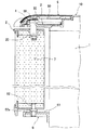
図1は、この発明の冷蔵庫の一実施形態である平面図を示している。図2は、図1のA−A断面図を示している。図1と図2に示すように、この冷蔵庫は、冷蔵庫本体1と、扉2と、上記扉2の上側で上記冷蔵庫本体1に設けられるヒンジ保持部材3と、上記扉2を上記ヒンジ保持部材3に対して回転可能に取り付けるヒンジピン4と、上記扉2の下側に配置されると共に上記扉2を上記冷蔵庫本体1に対して上記ヒンジピン4の軸回りに回転可能に取り付ける下ヒンジ部6と、上記冷蔵庫本体1に取り付けられると共に上記ヒンジ保持部材3および上記ヒンジピン4を覆うカバー部材5とを備える。すなわち、上記扉2は、上記ヒンジピン4の軸回りに回転し、上記冷蔵庫本体1に対して開閉可能になる。
FIG. 1: has shown the top view which is one Embodiment of the refrigerator of this invention. FIG. 2 shows an AA cross-sectional view of FIG. As shown in FIGS. 1 and 2, the refrigerator includes a refrigerator main body 1, a
上記冷蔵庫本体1の上部は、テーブル部10であり、このテーブル部10の上面は、テーブル面として利用される。なお、上記扉2を上下に複数個並列した冷蔵庫であって、この複数の扉2の何れかに、本発明のヒンジ構造を用いてもよい。
The upper part of the refrigerator body 1 is a
上記扉2は、左右両側のそれぞれの上部(上面)に取付孔20を有する。上記扉2の内部は、ウレタン等の断熱材7で満たされている。
The
上記ヒンジ保持部材3は、上記冷蔵庫本体1の上記テーブル部10の左右両側のそれぞれに設けられている。具体的に述べると、上記ヒンジ保持部材3は、プレート状であり、上記冷蔵庫本体1の上面に、ねじ等にて取り付けられている。また、上記ヒンジ保持部材3は、上記扉2の上記取付孔20の上側でこの取付孔20に重なる貫通孔30を有する。
The
上記ヒンジピン4は、上記ヒンジ保持部材3の上記貫通孔30の上側から、この貫通孔30に挿通され、上記扉2の上記取付孔20に抜き取り自在に差し込まれて、上記扉2を上記冷蔵庫本体1に対して回転可能に取り付ける。
The
上記下ヒンジ部6は、上記扉2の左右両側のそれぞれの下側に配置されると共に上記冷蔵庫本体1に取り付けられる支持部材61と、この支持部材61と上記扉2とを相対的に回転可能に連結する下ピン62とを備える。
The lower hinge portion 6 is disposed on the lower sides of the left and right sides of the
具体的に述べると、上記扉2は、左右両側のそれぞれの下部に孔部を有し、上記支持部材61は、上記扉2の下部の孔部に重なる孔部を有する。上記下ピン62は、上記下ピン62の軸方向の中央部に、鍔部62aを有する。そして、上記下ピン62の両端部は、それぞれ、上記扉2の下部の孔部と、上記支持部材61の孔部とに挿入され、上記下ピン62の鍔部62aは、上記扉2の下面と上記支持部材61との間に挟まれて、上記下ピン62は、上記扉2と上記支持部材61とに離脱自在に取り付けられる。
More specifically, the
上記ヒンジピン4は、右側の上記ヒンジ保持部材3に差し込まれている。上記下ピン62は、右側の上記支持部材61に差し込まれている。上記冷蔵庫本体1の右側にある上記ヒンジ保持部材3、上記ヒンジピン4および上記下ヒンジ部6により、上記扉2は、上記冷蔵庫本体1に対して上記ヒンジピン4の軸回りに回転可能になる。要するに、上記扉2は、右開きになる。なお、「右側」とは、冷蔵庫の扉に向かった正面視の右側をいう。
The
上記ヒンジ保持部材3と上記ヒンジピン4は、上記ヒンジピン4が上記扉2の上記取付孔20に差し込まれた状態で、上記ヒンジピン4の軸回り方向に相互に位置決めされている。具体的に述べると、上記ヒンジピン4の先端部は、Dカット加工を施され、上記扉2の上記取付孔20は、上記ヒンジピン4の先端部に対応する形状に形成されている。このように、簡単な構成で、上記ヒンジピン4と上記取付孔20とを嵌合することができる。
The
上記カバー部材5は、上記冷蔵庫本体1の上部の上記テーブル部10の左右両側のそれぞれに離脱自在に取り付けられる。左右の上記カバー部材5は、左右の上記ヒンジ保持部材3のそれぞれを覆う。上記左右のカバー部材5は、互いに対称に、形成されている。上記カバー部材5は、弾性変形して、上記テーブル部10の前縁部に着脱される。
The
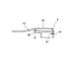
図3A、図3Bおよび図3Cに示すように、上記カバー部材5は、本体部50と、この本体部50に取り付けられたツメ部56、ガイド部57およびピン部58とを有する。このカバー部材5は、図1の右側のカバー部材5を示している。なお、図3Bは、図3AのX方向からみた図であり、図3Cは、図3AのY方向からみた図である。
As shown in FIGS. 3A, 3B, and 3C, the
この本体部50は、湾曲状に形成され、厚肉部50aと薄肉部50bとを有する。上記薄肉部50bにおける上記ヒンジ保持部材3に対向する面は、上記厚肉部50aにおける上記ヒンジ保持部材3に対向する面よりも、上記ヒンジ保持部材3から遠い位置にある。
The
上記薄肉部50bにおける上記ヒンジ保持部材3に対向する面と、上記厚肉部50aにおける上記ヒンジ保持部材3に対向する面との間には、段差部51が設けられている。この段差部51は、斜めにカットされて、形成されている。
A
つまり、上記薄肉部50bは、上記厚肉部50aに比べて、上記ヒンジ保持部材3側への押圧力に対する抵抗力が小さくなって、上記薄肉部50bは、弾性変形しやすくなる。
That is, the
上記ツメ部56は、上記薄肉部50bに連なっている。上記ツメ部56は、上記本体部50の一辺側に、一方向(上記冷蔵庫本体1の内側)に突出するように、設けられている。
The
上記ガイド部57は、複数設けられ、この複数のガイド部57は、上記一方向(上記冷蔵庫本体1の内側)に突出するように、設けられている。
A plurality of the
上記ピン部58は、上記本体部50における上記ヒンジ保持部材3に対向する面に、上記ヒンジ保持部材3側に突出するように、設けられている。
The
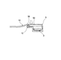
図2に示すように、上記ピン部58は、上記ヒンジピン4の真上に位置する。このピン部58は、上記ヒンジピン4が上記取付孔20に完全に差し込まれない状態で、上記ヒンジピン4に接触して、上記カバー部材5の上記冷蔵庫本体1への取り付けを阻止する一方、上記ヒンジピン4が上記取付孔20に完全に差し込まれた状態で、上記ヒンジピン4に接触せずに、上記カバー部材5の上記冷蔵庫本体1への取り付けを可能にする。
As shown in FIG. 2, the
図4と図5に示すように、上記冷蔵庫本体1のテーブル部10は、上記カバー部材5の上記ツメ部56を掛けるツメ部取付孔12と、上記カバー部材5の上記ガイド部57を挿入するガイド部取付孔14とを有する。なお、図4は、図1のB1−B1断面図を示し、図5は、図1のB2−B2断面図を示す。
As shown in FIGS. 4 and 5, the
上記ツメ部56を上記ツメ部取付孔12に掛けることで、上記カバー部材5は、上記冷蔵庫本体1に固定されると共に、上記ガイド部57を上記ガイド部取付孔14に一定方向(左右方向)に挿入することで、上記カバー部材5は、上記冷蔵庫本体1に位置決めされて、上記一定方向(左右方向)以外への動きを抑制される。つまり、上記ガイド部57が上記ガイド部取付孔14に挿入されて、上記カバー部材5は、前後方向および上下方向の動きが抑制され、上記カバー部材5が不意に上記テーブル部10から脱落することを防止する。
The
上記カバー部材5を弾性変形して上記ツメ部56を上記ツメ部取付孔12から外すと共に、上記カバー部材5を上記一定方向(左右方向)にスライドして上記ガイド部57を上記ガイド部取付孔14から抜き取ることで、上記カバー部材5は、上記冷蔵庫本体1から離脱される。
The
つまり、上記カバー部材5を取り外す際、図6Aに示すように、上記カバー部材5の上記ツメ部56付近の上面を指で押さえて、下方向の負荷をかける。上記カバー部材5の弾性変形により、上記ツメ部56の位置を無負荷状態の位置から下げて、上記ツメ部56の上記ツメ部取付孔12に対する掛かりをなくしてから、図6Bに示すように、上記ガイド部57による動きの抑制を受けていない左右方向に、上記カバー部材5をスライドさせることで、上記カバー部材5を上記テーブル部10から取り外すことができる。
That is, when removing the
図1と図7Aに示すように、上記冷蔵庫本体1の上記テーブル部10における上記左右のカバー部材5,5の間に位置する部分10aは、上記扉2の真上に張り出している。この張り出し部分10aの内部は、(ウレタン等の)断熱材7で満たされている。上記カバー部材5は、上記張り出し部分10aと同じ材質である。このため、上記カバー部材5を、上記張り出し部分10aに対して、色調や質感を合わすことができ、一体感を持たせることができる。なお、図7Aは、図1のC1−C1断面図である。
As shown in FIG. 1 and FIG. 7A, a
具体的に述べると、上記張り出し部分10a以外において、上記テーブル部10の上面と上記冷蔵庫本体1の外箱17との間に、第1の密閉空間が形成されている。上記張り出し部分10aにおいて、上記テーブル部10の上面とキャップ15との間に、第2の密閉空間が形成されている。
Specifically, a first sealed space is formed between the upper surface of the
上記第1の密閉空間と上記第2の密閉空間とは、孔16によって、繋がっており、上記断熱材7がウレタンである場合、ウレタン発泡の際に、上記断熱材7は、上記第1の密閉空間で発泡し、さらに、上記孔16を通過して、上記第2の密閉空間を満たす。
The first sealed space and the second sealed space are connected by a
上記テーブル部10に上記張り出し部分10aを設けているので、上記テーブル部10の上面で、ジュースや醤油等の液体がこぼれたり、埃が溜まっていたとしても、上記張り出し部分10aによって、上記扉2のパッキンへの進入を阻止して、衛生的に問題がない。
Since the protruding
図1と図7Bに示すように、上記テーブル部10は、上面部10bと、この上面部10bの裏面に設けられた複数のリブ部10cとを有する。なお、図7Bは、図1のC2−C2断面図である。
As shown in FIGS. 1 and 7B, the
上記上面部10bの肉厚tは、2.3mmであり、隣り合う上記リブ部10cのピッチPは、25mmである。このため、上記上面部10bに、耐熱グレード樹脂を用いなくても、上記上面部10bに、耐熱温度100℃を表示できる性質を持たせることができる。したがって、上記上面部10bに、安価な一般耐熱グレードの樹脂を用いても、上記上面部10bに、レンジなどを置くことが可能になる。
The wall thickness t of the upper surface portion 10b is 2.3 mm, and the pitch P between the
次に、上記扉2を右開きから左開きに変更する場合を説明する。
Next, a case where the
まず、上記左右のカバー部材5を弾性変形させて上記冷蔵庫本体1から取り外す。そして、上記扉2を閉じた状態で、上記扉2の右側の上記取付孔20、および、右側の上記ヒンジ保持部材3の上記貫通孔30に差し込まれている上記ヒンジピン4を抜き取る。
First, the left and
その後、上記扉2を上記冷蔵庫本体1から取り外して、上記ピン部62を右側の上記支持部材61から抜き取り、このピン部62を左側の上記支持部材61に差し込み、上記扉2の左側の下部の孔部を、上記ピン部62に差し込ませる。
Thereafter, the
そして、抜き取った上記ヒンジピン4を、左側の上記ヒンジ保持部材3の上記貫通孔30、および、上記扉2の左側の上記取付孔20に差し込むことで、上記扉2を左開きに変更することができる。そして、上記左右のカバー部材5を弾性変形させて上記冷蔵庫本体1に再度取り付ける。このように、専用工具を使用せず、容易に上記扉2の左右開きを変更することができる。
Then, by inserting the extracted
上記構成の冷蔵庫によれば、上記冷蔵庫本体1の左右両側のそれぞれに離脱自在に取り付けられると共に上記ヒンジ保持部材3および上記ヒンジピン4を覆うカバー部材5を備えるので、上記扉2の左右開きを変更するときに、左右の上記カバー部材5を個別に取り外して、上記ヒンジピン4を左右に差し変える。
According to the refrigerator having the above configuration, the left and right opening of the
したがって、上記カバー部材5は、上記冷蔵庫本体1の左右両側のそれぞれに設けられ、上記カバー部材5を小型に形成できるので、上記扉2の左右開きを変更するときに、上記カバー部材5の取り外しの作業スペースを小さくできる。また、上記カバー部材5の材料の量を、従来に比べて、少なくすることができ、冷蔵庫の左右にヒンジ構造が存在することを視覚的に示すことができる。
Therefore, since the
また、上記カバー部材5は、ツメ部56とガイド部57とを有し、上記冷蔵庫本体1は、上記ツメ部取付孔12と上記ガイド部取付孔14とを有し、上記ツメ部56を上記ツメ部取付孔12に掛けることで、上記カバー部材5は、上記冷蔵庫本体1に固定されると共に、上記ガイド部57を上記ガイド部取付孔14に一定方向に挿入することで、上記カバー部材5は、上記冷蔵庫本体1に位置決めされて、上記一定方向以外への動きを抑制されるので、簡単な構成で、上記カバー部材5の上記冷蔵庫本体1への固定および位置決めを行うことができる。
The
また、上記カバー部材5を弾性変形して上記ツメ部56を上記ツメ部取付孔12から外すと共に、上記カバー部材5を上記一定方向にスライドして上記ガイド部57を上記ガイド部取付孔14から抜き取ることで、上記カバー部材5は、上記冷蔵庫本体1から離脱されるので、専用工具を使用せずに上記カバー部材5を一度の作業で上記冷蔵庫本体1から取り外すことができる。
Further, the
また、上記薄肉部50bにおける上記ヒンジ保持部材3に対向する面は、上記厚肉部50aにおける上記ヒンジ保持部材3に対向する面よりも、上記ヒンジ保持部材3から遠い位置にあるので、上記薄肉部50bは、上記厚肉部50aに比べて、上記ヒンジ保持部材3側への押圧力に対する抵抗力が小さくなって、上記薄肉部50bは、弾性変形しやすくなる。したがって、上記薄肉部50bに連なっている上記ツメ部56を、上記ツメ部取付孔12に、容易に着脱できる。
Moreover, since the surface facing the
また、上記カバー部材5のピン部58は、上記ヒンジピン4が上記取付孔20に完全に差し込まれない状態で、上記ヒンジピン4に接触して、上記カバー部材5の上記冷蔵庫本体1への取り付けを阻止する一方、上記ヒンジピン4が上記取付孔20に完全に差し込まれた状態で、上記ヒンジピン4に接触せずに、上記カバー部材5の上記冷蔵庫本体1への取り付けを可能にするので、上記ヒンジピン4が上記取付孔20に確実に差し込まれていない状態で、上記カバー部材5を上記冷蔵庫本体1に取り付けようとすると、上記ピン部58が上記ヒンジピン4の上部に当接して、上記カバー部材5を上記冷蔵庫本体1に取り付けることができず、上記ヒンジピン4が上記取付孔20に確実に差し込まれているか否かを、容易に判断することができる。また、上記ピン部58にて上記ヒンジピン4の上記取付孔20からの抜けを防止することができる。
In addition, the
また、上記冷蔵庫本体1の張り出し部分10aの内部は、断熱材7で満たされているので、庫内からの冷気漏れを防ぐことができる。
Moreover, since the inside of the overhang |
これに対して、従来の冷蔵庫では、図8に示すように、カバー部材104は、冷蔵庫本体の左右に対して長尺に形成されているので、上記カバー部材104の材料の量が多くなると共に、冷蔵庫の左右にヒンジ構造が存在することを視覚的に示すことができない。
On the other hand, in the conventional refrigerator, as shown in FIG. 8, since the
また、従来の冷蔵庫では、図8と図9に示すように、上記カバー部材104の内部に、取外し機構105が設置されている。なお、図9は、図8のD−D断面図である。
Moreover, in the conventional refrigerator, as shown in FIGS. 8 and 9, a
詳しく述べると、上記カバー部材104の第1のツメ部125aが、冷蔵庫本体の上部のテーブル部103の取付孔126に掛かると共に、上記カバー部材104の第2のツメ部125bが、上記テーブル部103に設置された上記取外し機構105の先端にある抑止部124に掛かることによって、上記カバー部材104が上記テーブル部103に固定されている。
More specifically, the
そして、上記カバー部材104を取り外すには、上記取外し機構105を指などにより奥方向に押し、上記取外し機構105のばね構造113を収縮させることで、上記取外し機構105の上記抑止部124と上記カバー部材104の上記第2のツメ部125bとの掛かりを外した後、図10に示すように、上記カバー部材104を上方向に持ち上げ、上記カバー部材104の上記第1のツメ部125aと上記テーブル部103の上記取付孔126との掛かりを外すことで、上記カバー部材104の取外しを行っていた。
In order to remove the
このように、上記カバー部材104を取り外す際には、上記ばね構造113を収縮させると同時に、上記カバー部材104の上記第2のツメ部125bの掛かりを外す作業を行い、その後、上記カバー部材104の上記第1のツメ部125aの掛かりを外す作業を行っており、手間がかかっていた。
As described above, when the
また、上記カバー部材104に上記取外し機構105を収納しなくてはならず、その分、上記テーブル部103を厚くする必要がある。また、上記カバー部材104の内部に、上記取外し機構5が設置されているため、上記カバー部材104の内部に、ウレタン等の断熱材を満たすことはできない。
Further, the
なお、この発明は上述の実施形態に限定されない。例えば、上記下ヒンジ部6は、上記扉2の下面に設けられた切り欠き凹部(または凸部)と、上記冷蔵庫本体1に設けられると共に上記切り欠き凹部(または上記凸部)に嵌合する凸部(または切り欠き凹部)とを備えるようにしてもよい。
In addition, this invention is not limited to the above-mentioned embodiment. For example, the lower hinge portion 6 is provided in the notch recess (or projection) provided on the lower surface of the
1 冷蔵庫本体
10 テーブル部
10a 張り出し部分
10b 上面部
10c リブ部
12 ツメ部取付孔
14 ガイド部取付孔
15 キャップ
16 孔
17 外箱
2 扉
20 取付孔
3 ヒンジ保持部材
30 貫通孔
4 ヒンジピン
5 カバー部材
50 本体部
50a 厚肉部
50b 薄肉部
51 段差部
56 ツメ部
57 ガイド部
58 ピン部
6 下ヒンジ部
61 支持部材
62 下ピン
62a 鍔部
7 断熱材
103 テーブル部
104 カバー部材
105 取外し機構
113 ばね構造
124 抑止部
125a 第1のツメ部
125b 第2のツメ部
126 取付孔
DESCRIPTION OF SYMBOLS 1 Refrigerator
Claims (2)
左右両側のそれぞれの上部に取付孔を有する扉と、
上記冷蔵庫本体の左右両側のそれぞれに設けられると共に、上記取付孔の上側でこの取付孔に重なる貫通孔を有するヒンジ保持部材と、
上記貫通孔の上側からこの貫通孔に挿通され上記取付孔に抜き取り自在に差し込まれ、左右両側の上記貫通孔および上記取付孔に択一的に取り付けられて、上記扉を上記冷蔵庫本体に対して回転可能に取り付けるヒンジピンと、
上記扉の左右両側のそれぞれの下側に配置されると共に上記扉を上記冷蔵庫本体に対して上記ヒンジピンの軸回りに回転可能に取り付ける下ヒンジ部と、
上記冷蔵庫本体の左右両側のそれぞれに離脱自在に取り付けられると共に上記ヒンジ保持部材および上記ヒンジピンを覆うカバー部材と
を備え、
上記カバー部材は、ツメ部とガイド部とを有し、
上記冷蔵庫本体は、上記ツメ部を掛けるツメ部取付孔と、上記ガイド部を挿入するガイド部取付孔とを有し、
上記ツメ部を上記ツメ部取付孔に掛けることで、上記カバー部材は、上記冷蔵庫本体に固定されると共に、上記ガイド部を上記ガイド部取付孔に一定方向に挿入することで、上記カバー部材は、上記冷蔵庫本体に位置決めされて、上記一定方向以外への動きを抑制され、
上記カバー部材は、上記ツメ部および上記ガイド部が取り付けられた本体部を有し、
この本体部は、厚肉部と薄肉部とを有し、
上記薄肉部における上記ヒンジ保持部材に対向する面は、上記厚肉部における上記ヒンジ保持部材に対向する面よりも、上記ヒンジ保持部材から遠い位置にあり、
上記ツメ部は、上記薄肉部に連なり、上記ガイド部は、上記厚肉部に連なっていることを特徴とする冷蔵庫。 The refrigerator body,
Doors with mounting holes on the top of each of the left and right sides;
A hinge holding member that is provided on each of the left and right sides of the refrigerator main body and has a through hole that overlaps the mounting hole above the mounting hole,
The through hole is inserted into the through hole from the upper side of the through hole and is detachably inserted into the mounting hole, and is selectively attached to the through hole and the mounting hole on both the left and right sides, and the door is attached to the refrigerator body. A hinge pin that is rotatably mounted;
A lower hinge portion that is arranged on the lower side of each of the left and right sides of the door and that attaches the door to the refrigerator body so as to be rotatable about the axis of the hinge pin;
A cover member that is removably attached to each of the left and right sides of the refrigerator body and covers the hinge holding member and the hinge pin ,
The cover member has a claw portion and a guide portion,
The refrigerator body has a claw part mounting hole for hooking the claw part, and a guide part mounting hole for inserting the guide part,
The cover member is fixed to the refrigerator main body by hooking the claw portion on the claw portion attachment hole, and the cover member is inserted into the guide portion attachment hole in a certain direction by inserting the guide portion in a certain direction. , Positioned in the refrigerator body, the movement in the direction other than the certain direction is suppressed,
The cover member has a body portion to which the claw portion and the guide portion are attached,
The main body has a thick part and a thin part,
The surface facing the hinge holding member in the thin portion is located farther from the hinge holding member than the surface facing the hinge holding member in the thick portion,
The claw part is connected to the thin part, and the guide part is connected to the thick part .
上記カバー部材は、上記ヒンジピンの真上に位置するピン部を有し、
このピン部は、上記ヒンジピンが上記取付孔に完全に差し込まれない状態で、上記ヒンジピンに接触して、上記カバー部材の上記冷蔵庫本体への取り付けを阻止する一方、上記ヒンジピンが上記取付孔に完全に差し込まれた状態で、上記ヒンジピンに接触せずに、上記カバー部材の上記冷蔵庫本体への取り付けを可能にすることを特徴とする冷蔵庫。 The refrigerator according to claim 1 ,
The cover member has a pin portion located directly above the hinge pin,
The pin portion contacts the hinge pin in a state where the hinge pin is not completely inserted into the mounting hole and prevents the cover member from being attached to the refrigerator body, while the hinge pin is completely inserted into the mounting hole. The refrigerator, wherein the cover member can be attached to the refrigerator body without being in contact with the hinge pin in a state of being inserted into the refrigerator.
Priority Applications (1)
| Application Number | Priority Date | Filing Date | Title |
|---|---|---|---|
| JP2007278984A JP5132254B2 (en) | 2007-10-26 | 2007-10-26 | refrigerator |
Applications Claiming Priority (1)
| Application Number | Priority Date | Filing Date | Title |
|---|---|---|---|
| JP2007278984A JP5132254B2 (en) | 2007-10-26 | 2007-10-26 | refrigerator |
Publications (3)
| Publication Number | Publication Date |
|---|---|
| JP2009109035A JP2009109035A (en) | 2009-05-21 |
| JP2009109035A5 JP2009109035A5 (en) | 2010-08-12 |
| JP5132254B2 true JP5132254B2 (en) | 2013-01-30 |
Family
ID=40777707
Family Applications (1)
| Application Number | Title | Priority Date | Filing Date |
|---|---|---|---|
| JP2007278984A Active JP5132254B2 (en) | 2007-10-26 | 2007-10-26 | refrigerator |
Country Status (1)
| Country | Link |
|---|---|
| JP (1) | JP5132254B2 (en) |
Families Citing this family (2)
| Publication number | Priority date | Publication date | Assignee | Title |
|---|---|---|---|---|
| JP2012078009A (en) * | 2010-10-01 | 2012-04-19 | Sharp Corp | Refrigerator |
| WO2022210481A1 (en) * | 2021-04-02 | 2022-10-06 | シャープ株式会社 | Refrigerator |
Family Cites Families (7)
| Publication number | Priority date | Publication date | Assignee | Title |
|---|---|---|---|---|
| JPS6086889U (en) * | 1983-11-17 | 1985-06-14 | 株式会社東芝 | insulation box body |
| JPH0620024Y2 (en) * | 1988-05-09 | 1994-05-25 | ダイキン工業株式会社 | Air conditioner indoor unit |
| JPH03282180A (en) * | 1990-03-29 | 1991-12-12 | Sanyo Electric Co Ltd | Door for refrigerator and the like |
| JPH04132331U (en) * | 1991-05-27 | 1992-12-08 | 株式会社富士通ゼネラル | Air conditioner installation equipment |
| JP2004293913A (en) * | 2003-03-26 | 2004-10-21 | Sanyo Electric Co Ltd | Refrigerator |
| JP4217674B2 (en) * | 2004-08-26 | 2009-02-04 | シャープ株式会社 | Opening and closing structure of the refrigerator door |
| JP2006308203A (en) * | 2005-04-28 | 2006-11-09 | Sharp Corp | Refrigerator |
-
2007
- 2007-10-26 JP JP2007278984A patent/JP5132254B2/en active Active
Also Published As
| Publication number | Publication date |
|---|---|
| JP2009109035A (en) | 2009-05-21 |
Similar Documents
| Publication | Publication Date | Title |
|---|---|---|
| JP4963258B2 (en) | Opening and closing device of cold box | |
| JP5429451B2 (en) | Lid opening / closing device, electronic device, and image forming apparatus | |
| JP5132254B2 (en) | refrigerator | |
| JP6292525B2 (en) | Electronics | |
| JP2007034921A (en) | Electronic device | |
| JP6691366B2 (en) | Wall access door | |
| KR20070065139A (en) | Door open/close direction change structure for a drum washing machine | |
| JP4217674B2 (en) | Opening and closing structure of the refrigerator door | |
| JP2007101085A (en) | Wiring cover attachment structure | |
| JP5187971B2 (en) | Electrical equipment storage box | |
| JP6730494B1 (en) | Hinges and cabinets with hinges | |
| JP5451553B2 (en) | Combustion equipment | |
| JP2009236217A (en) | Seal member | |
| JP4809947B2 (en) | Panel mounting structure | |
| JP4384461B2 (en) | Inner lid for heat insulation of ceiling inspection port | |
| JP5093432B2 (en) | Display device | |
| JP5962415B2 (en) | Media slot door | |
| JP6106583B2 (en) | refrigerator | |
| JP4699485B2 (en) | Electronics | |
| JP4640111B2 (en) | Device display device | |
| JPH0128795Y2 (en) | ||
| JP4031762B2 (en) | Heat sink mounting structure for rice cookers | |
| JP2002094249A (en) | Structure for opening/closing operating part of electronic device unit | |
| JPS6135198Y2 (en) | ||
| KR200409808Y1 (en) | Emi shielding structure |
Legal Events
| Date | Code | Title | Description |
|---|---|---|---|
| A521 | Written amendment |
Free format text: JAPANESE INTERMEDIATE CODE: A523 Effective date: 20100624 |
|
| A621 | Written request for application examination |
Free format text: JAPANESE INTERMEDIATE CODE: A621 Effective date: 20100624 |
|
| A977 | Report on retrieval |
Free format text: JAPANESE INTERMEDIATE CODE: A971007 Effective date: 20120214 |
|
| A131 | Notification of reasons for refusal |
Free format text: JAPANESE INTERMEDIATE CODE: A131 Effective date: 20120306 |
|
| A521 | Written amendment |
Free format text: JAPANESE INTERMEDIATE CODE: A523 Effective date: 20120425 |
|
| TRDD | Decision of grant or rejection written | ||
| A01 | Written decision to grant a patent or to grant a registration (utility model) |
Free format text: JAPANESE INTERMEDIATE CODE: A01 Effective date: 20121016 |
|
| A01 | Written decision to grant a patent or to grant a registration (utility model) |
Free format text: JAPANESE INTERMEDIATE CODE: A01 |
|
| A61 | First payment of annual fees (during grant procedure) |
Free format text: JAPANESE INTERMEDIATE CODE: A61 Effective date: 20121106 |
|
| FPAY | Renewal fee payment (event date is renewal date of database) |
Free format text: PAYMENT UNTIL: 20151116 Year of fee payment: 3 |
|
| R150 | Certificate of patent or registration of utility model |
Free format text: JAPANESE INTERMEDIATE CODE: R150 Ref document number: 5132254 Country of ref document: JP Free format text: JAPANESE INTERMEDIATE CODE: R150 |