JP5132007B2 - lighting equipment - Google Patents
lighting equipment Download PDFInfo
- Publication number
- JP5132007B2 JP5132007B2 JP2012057067A JP2012057067A JP5132007B2 JP 5132007 B2 JP5132007 B2 JP 5132007B2 JP 2012057067 A JP2012057067 A JP 2012057067A JP 2012057067 A JP2012057067 A JP 2012057067A JP 5132007 B2 JP5132007 B2 JP 5132007B2
- Authority
- JP
- Japan
- Prior art keywords
- socket
- lighting
- lighting unit
- arm
- unit
- Prior art date
- Legal status (The legal status is an assumption and is not a legal conclusion. Google has not performed a legal analysis and makes no representation as to the accuracy of the status listed.)
- Expired - Fee Related
Links
Images

Landscapes
- Fastening Of Light Sources Or Lamp Holders (AREA)
- Non-Portable Lighting Devices Or Systems Thereof (AREA)
Description
本発明は、例えば住宅の天井面に取り付けられて廊下や壁等を照明するダウンライト等に用いられる照明器具に関する。 The present invention relates to a lighting apparatus used for a downlight or the like that is attached to a ceiling surface of a house and illuminates a corridor, a wall, or the like.
電球型LED光源を、その光軸方向がソケットの差し込み方向を軸として回転するようにした照明器具を既に提案している(例えば、特許文献1参照)。 There has already been proposed a lighting fixture in which a light bulb-type LED light source is rotated with its optical axis direction as the axis of the socket insertion direction (see, for example, Patent Document 1).
通常、白熱灯を蛍光灯やLED等の省エネ性に優れた代替光源へ置換する場合、ミニクリプトンランプ等の小型白熱光源を用いた薄型ダウンライトは照明器具の高さを押さえるためにランプが斜めに配置されていることが多い。 Normally, when replacing incandescent lamps with alternative light sources that excel in energy saving, such as fluorescent lamps and LEDs, thin downlights using small incandescent light sources such as mini-krypton lamps are slanted to keep the height of the luminaire low. It is often arranged in.
またLED電球等の代替光源はミニクリプトン電球よりも大きいため代替光源を取り付けることが非常に困難であり、装着できたとしても斜め方向へ照射されるために照明器具から照射される光が白熱灯の時と大きく変わるためランプを置換して代替使用することが困難であった。 Moreover, since the alternative light source such as the LED bulb is larger than the mini krypton bulb, it is very difficult to attach the alternative light source. It was difficult to replace the lamp and use it instead.
本発明は、前述した課題を解決するためになされたものであり、その目的は、ソケットへの装着を極めて簡単に行うことにより交換作業性の向上を図ることができる照明器具を提供することにある。 The present invention has been made to solve the above-described problems, and an object of the present invention is to provide a lighting apparatus capable of improving the exchange workability by performing the mounting to the socket very easily. is there.
本発明に係る照明器具は、アームと、前記アームに装着したソケットと、前記アームに固定される反射板と、端子台と、前記ソケットに嵌合される点灯ユニットと、を備え、住宅等の天井面に形成された取付穴に取り付けられる照明器具であって、前記ソケットを水平面に対して予め定められた角度で傾斜した状態で前記アームに組み付け、前記アームは、その側部に前記端子台を組み付けており、器具配線を通じて前記端子台を前記ソケット内に電気的に接続しており、前記反射板は、床面側を凹とした形状であって、前記点灯ユニットは、前記ソケットに嵌合する取付部と、当該取付部と前記ソケットの嵌合によって前記ソケットに電気的に接続される電源部と、照射方向を床面側へ向けたLEDを有し前記電源部と電気的に接続される点灯部と、を一体的に備え、前記点灯部は、前記取付部の前記ソケットに対する嵌合方向とは異なる方向であって床面側の方向へ、前記電源部に対し接続・分離可能であり、前記取付部が前記ソケットに嵌合した状態で、前記点灯部が前記電源部に接続される。 A lighting fixture according to the present invention includes an arm, a socket attached to the arm, a reflector fixed to the arm, a terminal block, and a lighting unit fitted into the socket, such as a house. A lighting fixture to be attached to a mounting hole formed in a ceiling surface, wherein the socket is assembled to the arm in a state inclined at a predetermined angle with respect to a horizontal plane, and the arm is connected to the terminal block on a side thereof. The terminal block is electrically connected to the socket through the instrument wiring, and the reflector has a concave shape on the floor surface side, and the lighting unit is fitted into the socket. A fitting part, a power supply part electrically connected to the socket by fitting of the attachment part and the socket, and an LED having an irradiation direction toward the floor surface side and electrically connected to the power supply part Be done Comprising a lighting unit, an integrally, the lighting unit, said a fitting direction with respect to the socket of the mounting portion of a different direction to the direction of the floor surface side, can be connected and separated with respect to the power supply unit The lighting part is connected to the power supply part in a state where the attachment part is fitted in the socket .
本発明の照明器具によれば、ソケットを有するアームと、アームのソケットに嵌合して商用電源を得る取付部と商用電源から得られた電気を調整する電源部と電源部から供給された電力で点灯するLEDを内蔵した点灯部とを有する点灯ユニットとを備えた。 According to the lighting apparatus of the present invention, an arm having a socket, a mounting portion that fits into the socket of the arm to obtain a commercial power source, a power source portion that adjusts electricity obtained from the commercial power source, and power supplied from the power source portion And a lighting unit having a lighting part with a built-in LED that lights up.
以下、本発明の一実施形態に係る照明器具についてダウンライトを例に図面を参照して説明する。 Hereinafter, a lighting apparatus according to an embodiment of the present invention will be described with reference to the drawings by taking a downlight as an example.
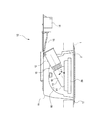
図1に示すように、本発明の一実施形態である照明器具10は、アーム11と、アーム11に装着したソケット12と、アーム11にネジにて固定される反射板16と、端子台14と、を備え、住宅等の天井面1に形成された取付穴2に取り付けられる。
As shown in FIG. 1, a
アーム11は、その側部に端子台14を組み付けており、器具配線15を通じて端子台14をソケット12内に電気的に接続している。
The
アーム11は反射板16を中央部に形成している。反射板16は図1中の下方である床面側を凹とした球面形状に形成されている。アーム11は、その下端部にフランジ形状の枠部材17を有する。
The
アーム11はソケット12を水平面A1に対して予め定められた角度α1だけ傾斜して組み付けている。
The
ソケット12には点灯ユニット13が嵌合される。点灯ユニット13は、取付部18と、電源部19と、点灯部20と、を一体的に備える。
A
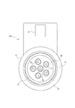
図2にも示すように、点灯部20は複数の例えば6個のLED(発光ダイオード)21を有し、中心の1個の周りに5個を放射状に配置している。
As shown in FIG. 2, the
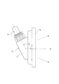
図3にも示すように、取付部18は若干の可撓性を有する樹脂材料を用いて成形されており、商用電源(図4参照)ACを得るために用いられる。電源部19は商用電源ACから得られた電気を直流電流に変換する等して調整する。点灯部20は電源部19から供給された直流電流でLED21を点灯させる。
As shown in FIG. 3, the
電源部19は点灯部20と分離可能に組み付けられている。そのため、点灯部20はLED21の明るさや光色や配光等の光学的特性の異なる仕様の点灯部20を適宜変更して電源部19に接続することができる。
従って、照明器具10は、明るさ、光色、配光等の光学的特性を適宜変更することにより光のコーディネートを簡単に行うことができる。
The
Therefore, the
電源部19と点灯部20とが分離可能であるために、電源部19をソケット12に先に装着し、その後に電源部19に点灯部20を接続することができる。
従って、照明器具10は、アーム11内の反射板16に干渉することなく点灯部20を確実に接続することができる。
Since the
Therefore, the
点灯部20は図3中の下方へ向けた照射方向を有する。点灯部20の照射方向と取付部18のソケット12への嵌合方向とは予め定められた角度α2を有している。角度α2は任意に設定変更することができる。
従って、照明器具10は、取付部18のソケット12への嵌合方向に対する点灯部20の照射方向を任意の方向に変更することにより、点灯部20の照射方向による光の演出を行うことができる。
The
Therefore, the
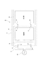
図4にも示すように、ソケット12は一対の端子22、23を有する。電源部19は取付部18のソケット12側に電気接続部である一対の端子24、25を有するとともに点灯部20側に一対の端子26、27を有する。点灯部20は電源部19側に一対の端子28、29を有する。
As shown also in FIG. 4, the
点灯部20の端子28、29は点灯部20を電源部19に接続することにより電源部19の端子26、27にそれぞれ電気的に接続される。
The
電源部19の端子24、25は点灯ユニット13をソケット12に嵌合することによりソケット12内の端子22、23にそれぞれ電気的に接続され、商用電源ACに接続される。
The
図5(A)にも示すように、取付部18には軸部30と筒部31と一対の可撓部32とを備えている。
As shown in FIG. 5A, the
軸部30はソケット12内に挿入される軸形状に形成されている。軸部30には電源部19の一対の端子24、25のうちの一方の端子24が収容されている。端子24は先端部を軸部30から突出している。
The
筒部31は軸部30の外側に円筒形状に形成されており、ソケット12の内径よりもわずかに小さいに外径を有する。
The
可撓部32は筒部31の対向する位置において筒部31からそれぞれ切欠かれており、軸部30に向けて可撓可能である。
The
可撓部32の外周部には電源部19の一対の端子24、25のうちの他方の端子25がそれぞれ被着されている。他方の端子25は、それぞれの先端部の外周部にロック手段の一方を構成する凹凸の係合突起部33を形成している。
The
図5(B)にも示すように、ソケット12は周板34と底板35とを有する。ソケット12内の一対の端子22、23は底板35に組み付けられている。
As shown in FIG. 5B, the
ソケット12内の一対の端子22、23のうちの他方の端子23は周板34の内周に配置されている。他方の端子23は、それぞれの先端部の外周部にロック手段の他方を構成する凹凸の係合突起受部36を形成している。
The
点灯ユニット13は、取付部18をソケット12内に挿入していくと、可撓部32がソケット12の周板34の内面に摺接することにより軸部30に向けて外径を小さくするように弾性変形しながらソケット12内に進行していく。
When the
図5(C)にも示すように、その後、軸部30の一方の端子24はソケット12の底板35の一方の端子22に電気的に接続される。
As shown in FIG. 5C, thereafter, one
同時に、可撓部32は弾性反発力を蓄積しているために、外径を大きくするように弾性復元する。これにより、弾性復元力により可撓部32の他方の端子25の係合突起部33が他方の端子23の係合突起受部36に係合されてロック状態となって保持され、他方の端子25が他方の端子23に電気的に接続される。
At the same time, since the
このように、点灯ユニット13は、ねじ込みを行うことなく、取付部18がソケット12へ差し込まれるだけの簡単な操作で各端子24、22および25、23の電気的な接続が行われる。
In this manner, the
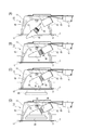
次に、照明器具10の組み立て手順について説明する。
Next, the assembly procedure of the
図6(A)にも示すように、まず、点灯ユニット13の電源部19と点灯部20とを分離しておく。ここで、例えばショップ等において、複数の仕様の点灯部20を用意しておき、使用者が選んだ点灯部20と電源部19とをセット販売するようにするのが望ましい。
As shown in FIG. 6A, first, the
図6(B)にも示すように、そして、電源部19だけを持って電源部19をソケット12に向けて進行していき、電源部19のみをソケット12に装着する。
As shown in FIG. 6B, the
電源部19は取付部18がソケット12へ差し込まれることにより、各端子24、22および25、23が電気的に接続される。
The
図6(C)に示すように、次に、電源部19に対して点灯部20を接続する。点灯部20は図6(C)中の下方から電源部19に向けて進行していく。
Next, as illustrated in FIG. 6C, the
図6(D)に示すように、点灯部20の電源部19への接続により、点灯部20の各端子28、29が電源部19の各端子26、27にそれぞれ電気的に接続される。
As shown in FIG. 6D, the
本発明の一実施形態の照明器具10では、点灯ユニット13はソケット12への嵌合によりアーム11に装着される。
これにより、点灯ユニット13は従来のソケット12にそのまま装着することができるので、アーム11への加工を不要にして代替光源への適用を簡単に行うことができる。
従って、ソケット12への装着を極めて簡単に行うことにより交換作業性の向上を図ることができる。
In the
Thereby, since the
Therefore, the replacement workability can be improved by mounting the
本発明の一実施形態の照明器具10では、点灯ユニット13はソケット12への差し込み等によりアーム11に装着される。
従って、従来のもののように、LED電球をソケットの最奥までねじ込んで電気接続をする必要がなくなるとともに、LED21の光軸選択がねじ込みの影響を受けることがない。
In the
Therefore, unlike the conventional one, there is no need to screw the LED bulb into the socket to make an electrical connection, and the optical axis selection of the LED 21 is not affected by the screwing.
本発明の一実施形態の照明器具10では、取付部18のソケット12への嵌合方向に対して点灯部20の照射方向を任意の方向に変更することができる。
従って、取付部18のソケット12への嵌合方向に対する点灯部20の照射方向を任意の方向に変更することにより、点灯部20の照射方向による光の演出を行うことができる。
In the
Therefore, by changing the irradiation direction of the
本発明の一実施形態の照明器具10では、点灯部20の構成を任意に変更して電源部19に結合することができる。
従って、明るさ、光色、配光等の光学的特性を変更することにより光のコーディネートを簡単に行うことができる。
In the
Therefore, it is possible to easily coordinate light by changing optical characteristics such as brightness, light color, and light distribution.
本発明の一実施形態の照明器具10では、点灯部20を電源部19から取り外しておいて電源部19をソケット12に装着し、その後に電源部19に点灯部20を接続することができる。
従って、アーム11内の反射板16に干渉することなく点灯部20を確実に接続することができる。
In the
Therefore, the
本発明の一実施形態の照明器具10では、点灯ユニット13は取付部18をソケット12に嵌合することにより端子24、25がソケット12の端子22、23に電気的に接続される。このとき、点灯ユニット13は各端子24、25に有する係合突起部33と各端子22、23に有する係合突起受部36とのロックによりソケット12に装着された状態を保持される。
従って、点灯ユニット13はソケット12に装着された状態で容易に脱落せずに通電回路を確実に形成することができる。
In the
Therefore, the
なお、前記各実施形態で使用したアーム11、ソケット12、反射板16、枠部材17等は例示したものに限定するものではなく適宜変更が可能である。
In addition, the
1 天井面
2 取付穴
10 照明器具
11 アーム
12 ソケット
13 点灯ユニット
14 端子台
15 器具配線
16 反射板
17 枠部材
18 取付部
19 電源部
20 点灯部
21 LED
24、25 端子(電気接続部)
33 係合突起部(ロック手段)
36 係合突起受部(ロック手段)
AC 商用電源
DESCRIPTION OF
24, 25 terminals (electrical connections)
33 Engaging protrusion (locking means)
36 Engagement projection receiving part (locking means)
AC commercial power
Claims (1)
前記アームに装着したソケットと、
前記アームに固定される反射板と、
端子台と、
前記ソケットに嵌合される点灯ユニットと、を備え、
住宅等の天井面に形成された取付穴に取り付けられる照明器具であって、
前記ソケットを水平面に対して予め定められた角度で傾斜した状態で前記アームに組み付け、
前記アームは、その側部に前記端子台を組み付けており、器具配線を通じて前記端子台を前記ソケット内に電気的に接続しており、
前記反射板は、床面側を凹とした形状であって、
前記点灯ユニットは、前記ソケットに嵌合する取付部と、当該取付部と前記ソケットの嵌合によって前記ソケットに電気的に接続される電源部と、照射方向を床面側へ向けたLEDを有し前記電源部と電気的に接続される点灯部と、を一体的に備え、
前記点灯部は、前記取付部の前記ソケットに対する嵌合方向とは異なる方向であって床面側の方向へ、前記電源部に対し接続・分離可能であり、前記取付部が前記ソケットに嵌合した状態で、前記点灯部が前記電源部に接続される、照明器具。 Arm,
A socket attached to the arm;
A reflector fixed to the arm;
A terminal block;
A lighting unit fitted in the socket,
It is a lighting fixture attached to a mounting hole formed on a ceiling surface of a house,
The socket is assembled to the arm in a state inclined at a predetermined angle with respect to a horizontal plane,
The arm has the terminal block assembled on its side, and the terminal block is electrically connected to the socket through instrument wiring,
The reflector has a concave shape on the floor side,
The lighting unit includes a mounting portion that fits into the socket, a power source that is electrically connected to the socket by fitting the mounting portion and the socket, and an LED whose irradiation direction is directed to the floor surface side. A lighting unit electrically connected to the power supply unit,
The lighting portion can be connected to and separated from the power supply portion in a direction different from the fitting direction of the mounting portion with respect to the socket and in the direction of the floor surface, and the mounting portion is fitted into the socket. In this state, the lighting unit is connected to the power source unit .
Priority Applications (1)
| Application Number | Priority Date | Filing Date | Title |
|---|---|---|---|
| JP2012057067A JP5132007B2 (en) | 2012-03-14 | 2012-03-14 | lighting equipment |
Applications Claiming Priority (1)
| Application Number | Priority Date | Filing Date | Title |
|---|---|---|---|
| JP2012057067A JP5132007B2 (en) | 2012-03-14 | 2012-03-14 | lighting equipment |
Related Parent Applications (1)
| Application Number | Title | Priority Date | Filing Date |
|---|---|---|---|
| JP2009014591A Division JP2010170955A (en) | 2009-01-26 | 2009-01-26 | Illumination fixture |
Publications (2)
| Publication Number | Publication Date |
|---|---|
| JP2012109282A JP2012109282A (en) | 2012-06-07 |
| JP5132007B2 true JP5132007B2 (en) | 2013-01-30 |
Family
ID=46494619
Family Applications (1)
| Application Number | Title | Priority Date | Filing Date |
|---|---|---|---|
| JP2012057067A Expired - Fee Related JP5132007B2 (en) | 2012-03-14 | 2012-03-14 | lighting equipment |
Country Status (1)
| Country | Link |
|---|---|
| JP (1) | JP5132007B2 (en) |
Cited By (1)
| Publication number | Priority date | Publication date | Assignee | Title |
|---|---|---|---|---|
| KR101539719B1 (en) * | 2013-11-07 | 2015-07-28 | 박노길 | Led lamp of directly attached |
Families Citing this family (2)
| Publication number | Priority date | Publication date | Assignee | Title |
|---|---|---|---|---|
| JP6041267B2 (en) * | 2013-05-13 | 2016-12-07 | パナソニックIpマネジメント株式会社 | lighting equipment |
| JP6498077B2 (en) * | 2015-08-24 | 2019-04-10 | みのる化成株式会社 | Mounting structure of lighting device for temporary toilet and temporary toilet provided with the same |
Family Cites Families (4)
| Publication number | Priority date | Publication date | Assignee | Title |
|---|---|---|---|---|
| JP3989794B2 (en) * | 2001-08-09 | 2007-10-10 | 松下電器産業株式会社 | LED illumination device and LED illumination light source |
| JP2005216495A (en) * | 2004-01-27 | 2005-08-11 | Matsushita Electric Works Ltd | Led unit with base |
| JP2008251444A (en) * | 2007-03-30 | 2008-10-16 | Toshiba Lighting & Technology Corp | Led bulb and lighting fixture |
| JP2008262763A (en) * | 2007-04-11 | 2008-10-30 | Koowa:Kk | Ceiling-embedded luminaire |
-
2012
- 2012-03-14 JP JP2012057067A patent/JP5132007B2/en not_active Expired - Fee Related
Cited By (1)
| Publication number | Priority date | Publication date | Assignee | Title |
|---|---|---|---|---|
| KR101539719B1 (en) * | 2013-11-07 | 2015-07-28 | 박노길 | Led lamp of directly attached |
Also Published As
| Publication number | Publication date |
|---|---|
| JP2012109282A (en) | 2012-06-07 |
Similar Documents
| Publication | Publication Date | Title |
|---|---|---|
| US8714785B2 (en) | Cap, socket device, and luminaire | |
| US8157408B2 (en) | Lighting apparatus | |
| WO2009154162A1 (en) | Led lamp | |
| JP2007134324A (en) | Electric bulb assembly and method of manufacturing electric bulb | |
| US20120187836A1 (en) | Lamp and lighting apparatus | |
| JP5438547B2 (en) | Connector | |
| JP2013542568A (en) | Uniform module light source | |
| CN104114943A (en) | Lighting arrangements | |
| JP2011134665A (en) | Lamp with base and lighting fixture | |
| JP5662065B2 (en) | Straight tube lamp and lighting device | |
| JP5132007B2 (en) | lighting equipment | |
| KR101869248B1 (en) | Ring type LED Lamp | |
| JP2010244872A (en) | Led lighting apparatus | |
| CN213810069U (en) | Lamp fitting | |
| KR101486227B1 (en) | Illumination device and assembly therewith | |
| JP2010170955A (en) | Illumination fixture | |
| JP2013093104A (en) | Lighting device and lighting fixture | |
| KR101341084B1 (en) | Light emitting diode downlight | |
| CN112483912A (en) | Lamp fitting | |
| KR20110048927A (en) | Led illuminator | |
| EP3203145A1 (en) | A lighting device | |
| KR200473660Y1 (en) | Removable type LED light fixture | |
| JP6279333B2 (en) | Lighting unit | |
| TWI638961B (en) | A led lamp and a lamp assembly having the same | |
| JP6924963B2 (en) | lighting equipment |
Legal Events
| Date | Code | Title | Description |
|---|---|---|---|
| A621 | Written request for application examination |
Free format text: JAPANESE INTERMEDIATE CODE: A621 Effective date: 20120321 |
|
| A871 | Explanation of circumstances concerning accelerated examination |
Free format text: JAPANESE INTERMEDIATE CODE: A871 Effective date: 20120406 |
|
| A975 | Report on accelerated examination |
Free format text: JAPANESE INTERMEDIATE CODE: A971005 Effective date: 20120418 |
|
| A131 | Notification of reasons for refusal |
Free format text: JAPANESE INTERMEDIATE CODE: A131 Effective date: 20120508 |
|
| A521 | Written amendment |
Free format text: JAPANESE INTERMEDIATE CODE: A523 Effective date: 20120626 |
|
| A131 | Notification of reasons for refusal |
Free format text: JAPANESE INTERMEDIATE CODE: A131 Effective date: 20120724 |
|
| A521 | Written amendment |
Free format text: JAPANESE INTERMEDIATE CODE: A523 Effective date: 20120830 |
|
| TRDD | Decision of grant or rejection written | ||
| A01 | Written decision to grant a patent or to grant a registration (utility model) |
Free format text: JAPANESE INTERMEDIATE CODE: A01 Effective date: 20121009 |
|
| A01 | Written decision to grant a patent or to grant a registration (utility model) |
Free format text: JAPANESE INTERMEDIATE CODE: A01 |
|
| A61 | First payment of annual fees (during grant procedure) |
Free format text: JAPANESE INTERMEDIATE CODE: A61 Effective date: 20121105 |
|
| FPAY | Renewal fee payment (prs date is renewal date of database) |
Free format text: PAYMENT UNTIL: 20151116 Year of fee payment: 3 |
|
| R150 | Certificate of patent (=grant) or registration of utility model |
Free format text: JAPANESE INTERMEDIATE CODE: R150 |
|
| LAPS | Cancellation because of no payment of annual fees |