JP5130276B2 - Wireless base station - Google Patents
Wireless base station Download PDFInfo
- Publication number
- JP5130276B2 JP5130276B2 JP2009263207A JP2009263207A JP5130276B2 JP 5130276 B2 JP5130276 B2 JP 5130276B2 JP 2009263207 A JP2009263207 A JP 2009263207A JP 2009263207 A JP2009263207 A JP 2009263207A JP 5130276 B2 JP5130276 B2 JP 5130276B2
- Authority
- JP
- Japan
- Prior art keywords
- power
- base station
- radio base
- signal
- estimation unit
- Prior art date
- Legal status (The legal status is an assumption and is not a legal conclusion. Google has not performed a legal analysis and makes no representation as to the accuracy of the status listed.)
- Expired - Fee Related
Links
- 238000012935 Averaging Methods 0.000 claims description 45
- 238000000034 method Methods 0.000 claims description 36
- 238000012545 processing Methods 0.000 claims description 33
- 230000005540 biological transmission Effects 0.000 claims description 22
- 238000010295 mobile communication Methods 0.000 description 17
- 125000004122 cyclic group Chemical group 0.000 description 14
- 230000004044 response Effects 0.000 description 8
- 230000000694 effects Effects 0.000 description 5
- 101000741965 Homo sapiens Inactive tyrosine-protein kinase PRAG1 Proteins 0.000 description 2
- 102100038659 Inactive tyrosine-protein kinase PRAG1 Human genes 0.000 description 2
- 230000003044 adaptive effect Effects 0.000 description 2
- 230000001427 coherent effect Effects 0.000 description 2
- 238000010586 diagram Methods 0.000 description 2
- 238000005259 measurement Methods 0.000 description 2
- 238000001774 stimulated Raman spectroscopy Methods 0.000 description 2
- 201000000913 Duane retraction syndrome Diseases 0.000 description 1
- 230000003111 delayed effect Effects 0.000 description 1
- 238000000162 direct recoil spectroscopy Methods 0.000 description 1
- 238000005562 fading Methods 0.000 description 1
- 230000007774 longterm Effects 0.000 description 1
- 238000000926 separation method Methods 0.000 description 1
Images

Classifications
-
- H—ELECTRICITY
- H04—ELECTRIC COMMUNICATION TECHNIQUE
- H04J—MULTIPLEX COMMUNICATION
- H04J11/00—Orthogonal multiplex systems, e.g. using WALSH codes
- H04J11/0023—Interference mitigation or co-ordination
- H04J11/0026—Interference mitigation or co-ordination of multi-user interference
- H04J11/0036—Interference mitigation or co-ordination of multi-user interference at the receiver
-
- H—ELECTRICITY
- H04—ELECTRIC COMMUNICATION TECHNIQUE
- H04B—TRANSMISSION
- H04B17/00—Monitoring; Testing
- H04B17/30—Monitoring; Testing of propagation channels
- H04B17/309—Measuring or estimating channel quality parameters
- H04B17/318—Received signal strength
- H04B17/327—Received signal code power [RSCP]
-
- H—ELECTRICITY
- H04—ELECTRIC COMMUNICATION TECHNIQUE
- H04B—TRANSMISSION
- H04B17/00—Monitoring; Testing
- H04B17/30—Monitoring; Testing of propagation channels
- H04B17/309—Measuring or estimating channel quality parameters
- H04B17/345—Interference values
-
- H—ELECTRICITY
- H04—ELECTRIC COMMUNICATION TECHNIQUE
- H04J—MULTIPLEX COMMUNICATION
- H04J13/00—Code division multiplex systems
- H04J13/0007—Code type
- H04J13/0055—ZCZ [zero correlation zone]
- H04J13/0059—CAZAC [constant-amplitude and zero auto-correlation]
Landscapes
- Engineering & Computer Science (AREA)
- Computer Networks & Wireless Communication (AREA)
- Signal Processing (AREA)
- Quality & Reliability (AREA)
- Physics & Mathematics (AREA)
- Electromagnetism (AREA)
- Mobile Radio Communication Systems (AREA)
Description
本発明は、無線基地局に関する。 The present invention relates to a radio base station.
LTE(Long Term Evolution)方式の移動通信システムでは、上りリンクにおいて送信される参照信号(RS:Reference Signal)は、CAZAC系列によって構成されている。 In an LTE (Long Term Evolution) mobile communication system, a reference signal (RS) transmitted in the uplink is configured by a CAZAC sequence.
かかるLTE方式の移動通信システムでは、無線基地局eNBは、受信した参照信号を用いて、無線基地局eNBにおける受信品質、例えば、SIR(Signal to Interference Ratio)を推定し、推定したSIRを用いて、所定制御処理を行うように構成されている。 In such an LTE mobile communication system, the radio base station eNB estimates received quality at the radio base station eNB, for example, SIR (Signal to Interference Ratio), using the received reference signal, and uses the estimated SIR. The predetermined control process is performed.
しかしながら、LTE方式では、無線基地局eNBにおいて、どのように、SIRを推定すべきかについて仕様化されていないという問題点があった。 However, the LTE system has a problem that the radio base station eNB does not specify how to estimate the SIR.
そこで、本発明は、上述の課題に鑑みてなされたものであり、参照信号を用いて、高精度に、無線基地局eNBにおける受信品質を推定することができる無線基地局を提供することを目的とする。 Therefore, the present invention has been made in view of the above-described problems, and an object of the present invention is to provide a radio base station that can estimate reception quality in the radio base station eNB with high accuracy using a reference signal. And
本発明の第1の特徴は、移動局から、時間領域及び周波数領域で振幅が一定であり自己相関が0である所定系列を用いて形成されている所定信号を受信するように構成されている無線基地局であって、前記移動局によって送信された前記所定信号の送信信号を構成する系列内の連続する所定数のサンプルと、前記無線基地局における該所定信号の受信信号を構成する系列内の連続する所定数のサンプルとの間の相関値を算出し、該相関値を用いて該所定信号の受信電力を算出するように構成されている信号電力推定部を具備することを要旨とする。 A first feature of the present invention is configured to receive a predetermined signal formed from a mobile station using a predetermined sequence having constant amplitude and zero autocorrelation in the time domain and the frequency domain. A radio base station, a predetermined number of consecutive samples in the sequence constituting the transmission signal of the predetermined signal transmitted by the mobile station, and the sequence constituting the reception signal of the predetermined signal in the radio base station And a signal power estimation unit configured to calculate a correlation value between a predetermined number of consecutive samples and to calculate received power of the predetermined signal using the correlation value. .
以上説明したように、本発明によれば、参照信号を用いて、高精度に、無線基地局eNBにおける受信品質を推定することができる無線基地局を提供することができる。 As described above, according to the present invention, it is possible to provide a radio base station that can estimate the reception quality in the radio base station eNB with high accuracy using a reference signal.
(本発明の第1の実施形態に係る移動通信システムの構成)
図1及び図2を参照して、本発明の第1の実施形態に係る移動通信システムの構成について説明する。
(Configuration of mobile communication system according to the first embodiment of the present invention)
With reference to FIG.1 and FIG.2, the structure of the mobile communication system which concerns on the 1st Embodiment of this invention is demonstrated.
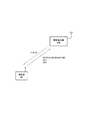
本実施形態に係る移動通信システムは、LTE方式の移動通信システムであって、図1に示すように、無線基地局eNBと、移動局UEとを具備している。 The mobile communication system according to the present embodiment is an LTE mobile communication system, and includes a radio base station eNB and a mobile station UE as shown in FIG.
図1に示すように、移動局UEは、上りリンクにおいて、物理信号として、SRS(Sounding Reference Signal、サウンディング参照信号)や、DRS(Demodulation Reference Signal、復調用参照信号)等を送信するように構成されている。 As shown in FIG. 1, the mobile station UE is configured to transmit SRS (Sounding Reference Signal, Sounding Reference Signal), DRS (Demodulation Reference Signal, Demodulation Reference Signal) and the like as physical signals in the uplink. Has been.
ここで、SRSは、無線基地局eNBによって、上りリンクの受信品質の測定や無線基地局eNBと移動局UEとの間のタイミングの測定等に用いられる参照信号である。 Here, the SRS is a reference signal used by the radio base station eNB for measurement of uplink reception quality, measurement of timing between the radio base station eNB and the mobile station UE, and the like.
なお、SRSは、PUSCH(Physical Uplink Shared Channel、物理上り共有チャネル)を介して送信される上りデータ信号やPUCCH(Physical Uplink Control Channel、物理上り制御チャネル)を介して送信される上り制御信号とは独立に周期的に送信される。 Note that the SRS is an uplink data signal transmitted via a PUSCH (Physical Uplink Shared Channel) and an uplink control signal transmitted via a PUCCH (Physical Uplink Channel, physical uplink control channel). Transmitted independently and periodically.
また、DRSは、PUSCHやPUCCHに時間多重される復調用の参照信号である。 The DRS is a demodulation reference signal that is time-multiplexed with the PUSCH or PUCCH.
また、移動局UEは、上りリンクにおいて、PUCCHを介して、上り制御信号として、PDSCH(Physical Downlink Shared Channel、物理下り共有チャネル)を介して送信された下りデータ信号に対する送達確認情報(ACK/NACK)や、下りリンクの受信品質(CQI:Channel Quality Indicator)等を送信するように構成されている。 Also, the mobile station UE transmits acknowledgment information (ACK / NACK) for a downlink data signal transmitted via PDSCH (Physical Downlink Shared Channel) as an uplink control signal via PUCCH in the uplink. ), Downlink reception quality (CQI: Channel Quality Indicator), and the like.
ここで、上述したSRSやDRSや上り制御信号は、時間領域及び周波数領域で振幅が一定であり自己相関が0である所定系列であるCAZAC(Constant Amplitude Zero Auto-Correlation)系列を用いて形成されている所定信号である。 Here, the above-described SRS, DRS, and uplink control signal are formed using a CAZAC (Constant Amplitude Zero Auto-Correlation) sequence, which is a predetermined sequence having constant amplitude and zero autocorrelation in the time domain and the frequency domain. Is a predetermined signal.
ここで、CAZAC系列に対して、サイクリックシフト(Cyclic Shift)を施すことによって、直交する複数の系列を生成することができる。すなわち、CAZAC系列は、サイクリックシフトによる多重可能な最大数を「NMAX」とした場合、サイクリックシフトにより生成された2つの異なる系列を構成する任意のKサンプル同士の相関値が「0」となるという特徴を有する。 Here, by applying a cyclic shift to the CAZAC sequence, a plurality of orthogonal sequences can be generated. That is, in the CAZAC sequence, when the maximum number that can be multiplexed by cyclic shift is “N MAX ”, the correlation value between arbitrary K samples constituting two different sequences generated by cyclic shift is “0”. It has the feature of becoming.
一般に、CAZAC系列の系列長を「M」とすると、1サンプルずつサイクリックシフトして系列を生成した場合に、最大でM個の系列を生成可能である。 Generally, if the sequence length of a CAZAC sequence is “M”, a maximum of M sequences can be generated when a sequence is generated by cyclic shifting one sample at a time.
しかしながら、マルチパスフェージング環境では、遅延波の影響により、どのサイクリックシフト量による系列なのかを見分けることが不可能になるため、マルチパスの最大遅延量よりも大きな値にサイクリックシフト量を決定する必要がある。 However, in a multipath fading environment, it becomes impossible to distinguish the cyclic shift amount due to the delay wave, so the cyclic shift amount is determined to be larger than the maximum multipath delay amount. There is a need to.
また、サイクリックシフト量を小さくして、系列数を多く取った場合には、符号多重数の増加による符号間干渉が大きくなるため、信号の分離精度が劣化する。 Also, when the cyclic shift amount is reduced and the number of sequences is increased, intersymbol interference due to an increase in the number of code multiplexes is increased, so that the signal separation accuracy is deteriorated.
したがって、上記の遅延波及び符号間干渉の影響を考慮してサイクリックシフト量を決定し、かかるサイクリックシフト量用いて生成した系列数が、前記最大多重数「NMAX」に相当する。ここで、「NMAX」には「NMAX≦M」の関係が成り立つ。 Therefore, the cyclic shift amount is determined in consideration of the influence of the delayed wave and intersymbol interference, and the number of sequences generated using the cyclic shift amount corresponds to the maximum multiplexing number “N MAX ”. Here, it established a relationship of "N MAX ≦ M" to "N MAX".
本実施形態に係る移動通信システムでは、例えば、CAZAC系列として、Zadoff-Chu系列や、Computer searchによるバイナリ系列等が用いられるように構成されている。 In the mobile communication system according to the present embodiment, for example, a Zadoff-Chu sequence, a binary sequence by Computer search, or the like is used as a CAZAC sequence.
また、無線基地局eNBは、下りリンクにおいて、PDCCH(Physical Downlink Control Channel、物理下り制御チャネル)を介して、スケジューリング信号や送信電力制御信号(TPC(Transmission Power Control)コマンド)等を含む下り制御信号を送信するように構成されている。 In addition, the radio base station eNB transmits a downlink control signal including a scheduling signal, a transmission power control signal (TPC (Transmission Power Control) command), etc. via a PDCCH (Physical Downlink Control Channel) in the downlink. Is configured to send.
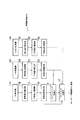
図2に示すように、無線基地局eNBは、SRS受信部11Aと、信号電力推定部11Bと、干渉電力推定部11Cと、受信品質推定部11Dと、DRS受信部12Aと、信号電力推定部12Bと、干渉電力推定部12Cと、受信品質推定部12Dと、PUCCH受信部13Aと、信号電力推定部13Bと、干渉電力推定部13Cと、受信品質推定部13Dと、スケジューリング処理部14と、TPCコマンド生成部15とを具備している。
As shown in FIG. 2, the radio base station eNB includes an
SRS受信部11Aは、移動局UEによって周期的に送信されているSRSを受信するように構成されている。
The
信号電力推定部11Bは、例えば、後述する図4に示す方法によって、移動局UEによって送信されたSRSの受信電力Spowerを算出するように構成されている。
The signal
干渉電力推定部11Cは、例えば、後述する図5に示す方法によって、無線基地局eNBにおけるSRSの受信信号r(n)に含まれる干渉電力Ipowerを算出するように構成されている。 The interference power estimation unit 11C is configured to calculate the interference power I power included in the SRS received signal r (n) in the radio base station eNB, for example, by the method shown in FIG. 5 described later.
受信品質推定部11Dは、信号電力推定部11Bによって算出された受信電力Spower及び干渉電力推定部11Cによって算出された干渉電力Ipowerを用いて、サブフレームごとに、無線基地局eNBにおけるSRSの受信品質(例えば、SIR)を算出するように構成されている。
The
ここで、受信品質推定部11Dは、信号電力推定部11Bによって算出された受信電力Spower及び干渉電力推定部11Cによって算出された干渉電力Ipowerに対して時間方向の平均化処理(すなわち、複数のサブフレームに渡る平均化処理)、及び、周波数方向の平均化(すなわち、複数のSRSの送信帯域に渡る平均化処理)を施した結果に基づいて、無線基地局eNBにおけるSRSのSIRを算出するように構成されていてもよい。
Here, the reception
また、受信品質推定部11Dは、干渉電力推定部11Cによって算出された干渉電力Ipowerに対して時間方向の平均化処理(すなわち、複数のサブフレームに渡る平均化処理)、及び、周波数方向の平均化(すなわち、複数のSRSの送信帯域に渡る平均化処理)を施した結果、及び、SRSの受信タイミングにおける信号電力推定部11Bによって算出された瞬時の受信電力Spowerに基づいて、無線基地局eNBにおけるSRSのSIRを算出するように構成されていてもよい。
In addition, the reception
このとき、信号電力推定部11Bによって算出された瞬時の受信電力Spowerは、周波数方向の平均化(すなわち、複数のSRSの送信帯域に渡る平均化処理)が施されたものであってもよい。
At this time, the instantaneous received power S power calculated by the signal
DRS受信部12Aは、移動局UEによって送信されているDRSを受信するように構成されている。
The DRS receiving
信号電力推定部12Bは、例えば、後述する図4に示す方法によって、移動局UEによって送信されたDRSの受信電力Spowerを算出するように構成されている。
The signal
干渉電力推定部12Cは、例えば、後述する図5に示す方法によって、無線基地局eNBにおけるDRSの受信信号r(n)に含まれる干渉電力Ipowerを算出するように構成されている。
The interference
受信品質推定部12Dは、信号電力推定部12Bによって算出された受信電力Spower及び干渉電力推定部12Cによって算出された干渉電力Ipowerを用いて、サブフレームごとに、無線基地局eNBにおけるDRSの受信品質(例えば、SIR)を算出するように構成されている。
The
ここで、受信品質推定部12Dは、信号電力推定部12Bによって算出された受信電力Spower及び干渉電力推定部12Cによって算出された干渉電力Ipowerに対して時間方向の平均化処理(すなわち、複数のサブフレームに渡る平均化処理)、及び、周波数方向の平均化(すなわち、複数のDRSの送信帯域に渡る平均化処理)を施した結果に基づいて、無線基地局eNBにおけるDRSのSIRを算出するように構成されていてもよい。
Here, the reception
また、受信品質推定部12Dは、干渉電力推定部12Cによって算出された干渉電力Ipowerに対して時間方向の平均化処理(すなわち、複数のサブフレームに渡る平均化処理)、及び、周波数方向の平均化(すなわち、複数のDRSの送信帯域に渡る平均化処理)を施した結果、及び、DRSの受信タイミングにおける信号電力推定部12Bによって算出された瞬時の受信電力Spowerに基づいて、無線基地局eNBにおけるDRSのSIRを算出するように構成されていてもよい。
In addition, the reception
このとき、信号電力推定部12Cによって算出された瞬時の受信電力Spowerは、周波数方向の平均化(すなわち、複数のDRSの送信帯域に渡る平均化処理)が施されたものであってもよい。
At this time, the instantaneous received power S power calculated by the
PUCCH受信部13Aは、移動局UEによってPUCCHを介して送信されている上り制御信号を受信するように構成されている。
The PUCCH receiving
信号電力推定部13Bは、例えば、後述する図4に示す方法によって、移動局UEによって送信された上り制御信号の受信電力Spowerを算出するように構成されている。 The signal power estimation unit 13B is configured to calculate the reception power S power of the uplink control signal transmitted by the mobile station UE, for example, by the method shown in FIG. 4 described later.
干渉電力推定部13Cは、例えば、後述する図5に示す方法によって、無線基地局eNBにおける上り制御信号の受信信号r(n)に含まれる干渉電力Ipowerを算出するように構成されている。 The interference power estimation unit 13C is configured to calculate the interference power I power included in the reception signal r (n) of the uplink control signal in the radio base station eNB, for example, by the method shown in FIG. 5 described later.
受信品質推定部13Dは、信号電力推定部13Bによって算出された受信電力Spower及び干渉電力推定部13Cによって算出された干渉電力Ipowerを用いて、サブフレームごとに、無線基地局eNBにおける上り制御信号の受信品質(例えば、SIR)を算出するように構成されている。
The reception
ここで、受信品質推定部13Dは、信号電力推定部13Bによって算出された受信電力Spower及び干渉電力推定部13Cによって算出された干渉電力Ipowerに対して時間方向の平均化処理(すなわち、複数のサブフレームに渡る平均化処理)、及び、周波数方向の平均化(すなわち、複数のPUCCHの送信帯域に渡る平均化処理)を施した結果に基づいて、無線基地局eNBにおける上り制御信号のSIRを算出するように構成されていてもよい。
Here, the reception
また、受信品質推定部13Dは、干渉電力推定部13Cによって算出された干渉電力Ipowerに対して時間方向の平均化処理(すなわち、複数のサブフレームに渡る平均化処理)、及び、周波数方向の平均化(すなわち、複数のPUCCHの送信帯域に渡る平均化処理)を施した結果、及び、上り制御信号の受信タイミングにおける信号電力推定部13Bによって算出された瞬時の受信電力Spowerに基づいて、無線基地局eNBにおける上り制御信号のSIRを算出するように構成されていてもよい。
In addition, the reception
このとき、信号電力推定部13Cによって算出された瞬時の受信電力Spowerは、周波数方向の平均化(すなわち、複数のPUCCHの送信帯域に渡る平均化処理)が施されたものであってもよい。 At this time, the instantaneous received power S power calculated by the signal power estimation unit 13C may be subjected to averaging in the frequency direction (that is, averaging processing over transmission bands of a plurality of PUCCHs). .
スケジューリング処理部14は、受信品質推定部11D及び受信品質推定部12Dによって算出された無線基地局eNBにおけるSIRに基づいて、所定制御処理、すなわち、時間・周波数スケジューリング処理や適応変復調(AMC:Adaptive Modulation and channel Coding)処理(変調方式及び符号化率の選択処理)等を行うように構成されている。
Based on the SIR in the radio base station eNB calculated by the reception
TPCコマンド生成部15は、受信品質推定部11Dと受信品質推定部12Dと受信品質推定部13Dとによって算出された無線基地局eNBにおけるSIRに基づいて、所定制御処理、すなわち、上りリンクにおける送信電力制御処理(例えば、TPCコマンドの生成処理及びPDCCHを介した移動局UEへの送信処理)を行うように構成されている。
The TPC
(本発明の第1の実施形態に係る移動通信システムの動作)
図3乃至図5を参照して、本発明の第1の実施形態に係る移動通信システムの動作について、具体的には、本発明の第1の実施形態に係る無線基地局eNBの動作について説明する。
(Operation of the mobile communication system according to the first embodiment of the present invention)
With reference to FIG. 3 to FIG. 5, the operation of the mobile communication system according to the first embodiment of the present invention, specifically, the operation of the radio base station eNB according to the first embodiment of the present invention will be described. To do.
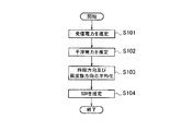
図3に示すように、ステップS101において、無線基地局eNBは、移動局UEによって送信されたSRSやDRSや上り制御信号の受信電力Spowerを推定する。ここで、図4を参照して、SRSを用いた受信電力Spowerの推定方法について説明する。 As shown in FIG. 3, in step S101, the radio base station eNB estimates the received power S power of the SRS, DRS, and uplink control signal transmitted by the mobile station UE. Here, with reference to FIG. 4, a method of estimating the received power S power using SRS will be described.
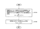
図4に示すように、例えば、無線基地局eNBの信号電力推定部11Bは、ステップS101Aにおいて、移動局UE#Lによって送信されたSRSの送信信号XL(n)を構成する系列内の連続する所定数Nのサンプル「a」〜「a+N−1」と、無線基地局eNBにおけるSRSの受信信号r(n)を構成する系列内の連続する所定数Nのサンプル「a」〜「a+N−1」との間の相関値Z(a)を算出し、ステップS101Bにおいて、相関値Z(a)を用いてSRSの受信電力Spowerを算出する。
As illustrated in FIG. 4, for example, the signal
具体的には、SRSの受信信号r(n)は、

によって表される。 Represented by
「n」は、「0」乃至「M」の範囲内の整数の値を取るパラメータであり、「M」は、SRSを構成する系列の長さである。また、「Xk(n)」は、移動局UE#kによって送信されたSRSの周波数領域の送信信号であり、「Hk(n)」は、移動局UE#kと無線基地局eNBとの間の伝搬路状態、すなわち、周波数応答であり、「N(n)」は、無線基地局eNBにおいて受信される干渉電力である。 “N” is a parameter that takes an integer value within the range of “0” to “M”, and “M” is the length of the sequence that constitutes the SRS. Further, “X k (n)” is a transmission signal in the frequency domain of the SRS transmitted by the mobile station UE # k, and “H k (n)” is the mobile station UE # k, the radio base station eNB, Is the frequency response, and “N (n)” is the interference power received at the radio base station eNB.
ここで、干渉電力とは、無線基地局eNBで付加される熱雑音及び他セルからの干渉電力の和である。さらに、「K」は、当該サブフレームにおけるSRSに多重されている移動局UEの数であり、「K≦NMAX」が成立する。なお、「N(n)」の分散は、「σ2」であるものとする。 Here, the interference power is the sum of thermal noise added by the radio base station eNB and interference power from other cells. Furthermore, “K” is the number of mobile stations UE multiplexed on the SRS in the subframe, and “K ≦ N MAX ” is established. Note that the variance of “N (n)” is “σ 2 ”.
ここで、信号電力推定部11Bは、
によって、相関値Z(a)を算出し、
![]()
![]()
によって、SRSの受信電力Spowerを算出するように構成されていてもよい。 May be configured to calculate the received power S power of the SRS.
以下、(式1)及び(式2)によって、SRSの受信電力Spowerを算出する理由について説明する。 Hereinafter, the reason for calculating the received power S power of the SRS will be described using (Expression 1) and (Expression 2).
第1に、移動局UE#Lによって送信されたSRSの受信電力を算出することを想定する。 First, it is assumed that the received power of the SRS transmitted by the mobile station UE # L is calculated.
かかる場合、無線基地局eNBは、各移動局UEに対して、送信すべきSRSを構成する系列やSRSの送信タイミングやSRSの送信周波数を割り当てるため、各移動局UEによって送信されるSRSを構成する系列「X(n)」について既知であるため、移動局UE#Lによって送信されたSRSを構成する系列「XL(n)」を用いて、以下のように、相関値Z(a)を算出する。
ここで、「Z(a)」は、系列内のサンプル「a」からスタートした場合の連続するNサンプルに渡る「XL(n)」と「r(n)」との間の相関値である。 Here, "Z (a)" is a correlation between across N consecutive samples in the case of starting from the sample in the sequence "a" and "X L (n)" and "r (n)" is there.
(式3)に示す「Z(a)」の第1項は、移動局UE#Lと無線基地局eNBとの間の伝搬路状態の推定値と等価であり、移動局UE#Lによって送信されたSRSの受信電力成分である。 The first term of “Z (a)” shown in (Equation 3) is equivalent to the estimated value of the propagation path state between the mobile station UE # L and the radio base station eNB, and is transmitted by the mobile station UE # L. The received SRS received power component.
また、(式3)に示す「Z(a)」の第2項は、同一のセル内で同一のSRSに多重された移動局UE#L以外の移動局UEからの干渉電力成分である。さらに、(式3)に示す「Z(a)」の第3項は、他セルからの干渉電力成分である。 Further, the second term of “Z (a)” shown in (Expression 3) is an interference power component from the mobile station UE other than the mobile station UE # L multiplexed on the same SRS in the same cell. Further, the third term of “Z (a)” shown in (Expression 3) is an interference power component from another cell.
ここで、簡素化のため、任意のNサンプルにおいて、周波数応答が一定である、すなわち、コヒーレントとであると見なせるものと仮定すると、「n=a,a+1,…a+N−1」のN個の周波数応答のサンプルは全て等しくなる。かかる周波数応答を「HL(n)=H’」とする。 Here, for simplification, assuming that the frequency response is constant in any N samples, that is, can be regarded as coherent, N number “n = a, a + 1,... A + N−1” All frequency response samples are equal. The frequency response is “H L (n) = H ′”.
かかる場合、周波数応答の変動に起因するサイクリックシフトによる多重を行った際の直交性の崩れを無視することができ、CAZAC系列をサイクリックシフトすることによって生成された系列は全て直交する、したがって、(式3)に示す「Z(a)」の第2項は、理想的には「0」となる。 In such a case, the loss of orthogonality when performing multiplexing by cyclic shift due to frequency response fluctuations can be ignored, and the sequences generated by cyclic shifting CAZAC sequences are all orthogonal, and therefore The second term of “Z (a)” shown in (Expression 3) is ideally “0”.
また、サンプル数Nが十分大きい場合には、(式3)に示す「Z(a)」の第3項は、平均化効果によって、ノイズ成分である「N(n)」が抑圧され、理想的には「0」となる。(式3)に示す「Z(a)」の第3項は、実際には、「0」にはならないが、SRSの受信電力成分である(式3)に示す「Z(a)」の第1項と比べて十分に小さくなるので無視することが可能である。 When the number of samples N is sufficiently large, the third term of “Z (a)” shown in (Equation 3) suppresses the noise component “N (n)” by the averaging effect, and is ideal. Thus, it is “0”. The third term of “Z (a)” shown in (Expression 3) is not actually “0”, but it is the received power component of SRS of “Z (a)” shown in (Expression 3). Since it is sufficiently smaller than the first term, it can be ignored.
したがって、理想的には、(式3)に示されるZ(a)について、以下のように単純化することができる。
ここで、CAZAC系列を構成するサンプルの振幅値の二乗値は「1」であるものと仮定している。 Here, it is assumed that the square value of the amplitude value of the samples constituting the CAZAC sequence is “1”.
したがって、以下のように、SRSの受信電力Spowerを算出することができる。
![]()
![]()
ここで、サンプル数Nは、サイクリックシフトによる多重可能な最大数NMAXの整数倍であれば、任意の値を取ることができる。したがって、「N=NMAX」とすれば、最小の平均化区間となるため、小さい周波数帯域幅あたりのSRSの受信電力Spowerを算出することができ、「N=M」とすれば、系列全体に渡っての平均化区間となるため、大きい周波数帯域幅あたりのSRSの受信電力Spowerを算出することができる。このため、算出すべきSIRの用途に応じて、サンプル数Nを使い分けることが可能である。 Here, the sample number N can take any value as long as it is an integer multiple of the maximum number N MAX that can be multiplexed by cyclic shift. Therefore, if “N = N MAX ”, the minimum averaging interval is obtained, so that the received power S power of the SRS per small frequency bandwidth can be calculated, and if “N = M”, the sequence Since this is an averaging interval over the whole, the received power S power of SRS per large frequency bandwidth can be calculated. For this reason, it is possible to selectively use the number N of samples according to the use of the SIR to be calculated.
例えば、SRSの系列の長さが「120」である場合、SRSは、1サブキャリアおきに周波数方向にマッピングされるため、最大で20リソースブロック(RB:Resource Block)に渡ってSRSの受信電力Spowerを算出することができる。 For example, when the length of the SRS sequence is “120”, since the SRS is mapped in the frequency direction every other subcarrier, the received power of the SRS over a maximum of 20 resource blocks (RBs). S power can be calculated.
ここで、SRSが、両端のRBを除くRB#2〜#21に渡ってマッピングされているものとする。
Here, it is assumed that SRS is mapped over
かかる場合、Z(a)を算出する場合に、「a=0」及び「N=24」とすると、RB#2〜#5の4RBに渡ってのSRSの受信電力Spowerを算出することができ、Z(a)を算出する場合に、「a=24」及び「N=24」とすると、RB#6〜#9の4RBに渡ってのSRSの受信電力Spowerを算出することができ、Z(a)を算出する場合に、「a=48」及び「N=24」とすると、RB#10〜#13の4RBに渡ってのSRSの受信電力Spowerを算出することができ、Z(a)を算出する場合に、「a=72」及び「N=24」とすると、RB#14〜#17の4RBに渡ってのSRSの受信電力Spowerを算出することができ、Z(a)を算出する場合に、「a=96」及び「N=24」とすると、RB#18〜#21の4RBに渡ってのSRSの受信電力Spowerを算出することができる。
In this case, when calculating Z (a), assuming that “a = 0” and “N = 24”, it is possible to calculate the received power S power of the SRS over 4 RBs of
一方、Z(a)を算出する場合に、「a=0」及び「N=120」とすると、RB#2〜#21の広帯域に渡ってのSRSの受信電力Spowerを算出することができる。
On the other hand, when calculating Z (a), if “a = 0” and “N = 120”, it is possible to calculate the received power S power of SRS over a wide band of
無線基地局eNBの信号電力推定部12Bは、上述した信号電力推定部11Bと同様の方法で、DRSの受信電力Spowerを算出するように構成されていてもよい。
The signal
また、無線基地局eNBの信号電力推定部13Bも、上述した信号電力推定部11Bと同様の方法で、上り制御信号の受信電力Spowerを算出するように構成されていてもよい。
Also, the signal power estimation unit 13B of the radio base station eNB may be configured to calculate the reception power S power of the uplink control signal by the same method as the signal
ステップS102において、無線基地局eNBは、無線基地局eNBにおけるSRS、DRS及び上り制御信号の受信信号r(n)に含まれる干渉電力Ipowerを推定する。ここで、図5を参照して、SRSを用いた干渉電力Ipowerの推定方法について説明する。 In step S102, the radio base station eNB estimates the interference power I power included in the received signal r (n) of the SRS, DRS, and uplink control signal in the radio base station eNB. Here, a method for estimating the interference power I power using SRS will be described with reference to FIG.
図5に示すように、例えば、無線基地局eNBの干渉電力推定部11Cは、ステップS102Aにおいて、スライディング相関を行う、すなわち、上述の連続する所定数Nのサンプル内の先頭サンプル「a」をスライドさせて、Z(a)、Z(a+1)及びZ(a+2)を算出する。 As illustrated in FIG. 5, for example, the interference power estimation unit 11C of the radio base station eNB performs sliding correlation in step S102A, that is, slides the first sample “a” in the predetermined number N of consecutive samples described above. To calculate Z (a), Z (a + 1) and Z (a + 2).
ここで、Z(a)、Z(a+1)及びZ(a+2)は、以下のように算出される。
ここで、サイクリックシフトによる直交が理想的に実現できており、所望の移動局UE#L以外の移動局UEからの受信電力成分は、完全に除去できていると仮定している。かかる場合、所望の干渉電力Ipowerは、N(n)の分散σ2となる。S(a)、S(a+1)及びS(a+2)は、かかる場合の理想的なSRSの受信電力成分であり、以下のように表される。
ステップS102Bにおいて、無線基地局eNBの干渉電力推定部11Cは、かかるZ(a)、Z(a+1)及びZ(a+2)を用いて、(式5)に示すように、複数の干渉電力サンプルItmp(a)を算出する。
![]()
![]()
以下、(式5)によって、干渉電力サンプルItmp(a)を算出する理由について説明する。 Hereinafter, the reason why the interference power sample I tmp (a) is calculated by (Equation 5) will be described.
(式4)において、第1項は、移動局UE#Lによって送信されたSRSの受信電力成分であり、第2項は、算出すべき干渉電力成分である。 In (Expression 4), the first term is a received power component of the SRS transmitted by the mobile station UE # L, and the second term is an interference power component to be calculated.
例えば、隣接するサブキャリアの周波数応答が等しい、すなわち、周波数変動が小さい場合には、S(a)及びS(a+1)がほぼ等しくなると解することができるため、Z(a)とZ(a+1)との差分によって、上述の干渉電力成分を算出することが可能であると解する。 For example, when the frequency responses of adjacent subcarriers are the same, that is, when the frequency fluctuation is small, it can be understood that S (a) and S (a + 1) are almost equal, so Z (a) and Z (a + 1) It is understood that the above-described interference power component can be calculated by the difference from
しかしながら、実際には、周波数変動は多少なりとも存在するため、(式5)に示すように、Z(a)とZ(a+2)との平均値、すなわち、Z(a)とZ(a+1)との間の中間値を、Z(a+1)から減算することによって、精度よく、移動局UE#Lによって送信されたSRSの受信電力成分を除去し、干渉電力サンプルItmp(a)を算出することができる。 However, in practice, since there is some frequency variation, as shown in (Equation 5), the average value of Z (a) and Z (a + 2), that is, Z (a) and Z (a + 1) Is subtracted from Z (a + 1), the received power component of the SRS transmitted by the mobile station UE # L is accurately removed, and the interference power sample I tmp (a) is calculated. be able to.
ステップS102Cにおいて、無線基地局eNBの干渉電力推定部11Cは、(式6)に示すように、複数の干渉電力サンプルItmp(a)に対して平均化処理を施すことによって、無線基地局eNBにおける所定信号の受信信号r(n)に含まれる干渉電力Ipowerを算出する。
以下、(式6)によって、干渉電力Ipowerを算出する理由について説明する。 Hereinafter, the reason for calculating the interference power I power will be described using (Equation 6).
複数の干渉電力サンプルItmp(a)を計算する際に登場する理想的な受信電力成分であるS(a)、S(a+1)及びS(a+2)に注目すると、S(a)、S(a+1)及びS(a+2)は、N個のサンプルにわたっての周波数応答成分の平均値である。したがって、S(a)とS(a+1)との間で、周波数変動が十分小さい、すなわち、コヒーレントである場合には、「n=a,a+1,…a+N−1」のN個の周波数応答のサンプルは全て等しくなるため、「S(a)≒S(a+1)」の関係が成り立つ。また、同様に、「S(a+1)≒S(a+2)」の関係も成り立つ。 Focusing on S (a), S (a + 1), and S (a + 2), which are ideal received power components that appear when calculating a plurality of interference power samples I tmp (a), S (a), S ( a + 1) and S (a + 2) are average values of frequency response components over N samples. Therefore, when the frequency variation between S (a) and S (a + 1) is sufficiently small, that is, coherent, N frequency responses of “n = a, a + 1,... A + N−1” Since the samples are all equal, the relationship “S (a) ≈S (a + 1)” is established. Similarly, the relationship “S (a + 1) ≈S (a + 2)” holds.
したがって、かかる関係を利用すると、上述の(式5)は、以下のように展開することができる。
1個の干渉電力サンプルItmp(a)では、サンプル数が少なく、誤差も大きくなるため、無線基地局eNBの干渉電力推定部11Cは、スライディング相関を行う、すなわち、上述の連続する所定数Nのサンプル内の先頭サンプル「a」をスライドさせて、複数の干渉電力サンプルItmp(a),(a=0,1,…M−N−2)を算出し、かかる複数の干渉電力サンプルItmp(a)に対して集合平均処理を施すことによって、上述の干渉電力Ipowerを算出する。 In one interference power sample I tmp (a), since the number of samples is small and the error is large, the interference power estimation unit 11C of the radio base station eNB performs sliding correlation, that is, the above-described predetermined predetermined number N The first sample “a” in the samples is slid to calculate a plurality of interference power samples I tmp (a), (a = 0, 1,... M−N−2), and the plurality of interference power samples I are calculated. The interference power I power described above is calculated by performing a set averaging process on tmp (a).
(式6)に示すように、「Itmp(a)」は、干渉成分の複素信号であるため、「Itmp(a)」に対して「Itmp(a)」の複素共役「Itmp(a)*」を乗算することによって、電力相当の成分を算出する。 As shown in (Expression 6), “I tmp (a)” is a complex signal of an interference component, and therefore, complex conjugate “I tmp ” of “I tmp (a)” with respect to “I tmp (a)”. (A) Calculates a component corresponding to electric power by multiplying * ”.
なお、(式6)は、以下の(式7)ように、展開可能である。
ここで、E[]は、集合平均化処理の演算を示し、かかる集合平均化処理の演算では、CAZAC系列である「XL(n)」の電力値が「1」となるものと仮定する。 Here, E [] indicates the operation of the set averaging process, and it is assumed that the power value of “X L (n)” that is the CAZAC sequence is “1” in the operation of the set averaging process. .
なお、(式7)では、(1/N)という係数が存在するため、(式8)に示すように、「Itmp(a)」と「Itmp(a)」の複素共役「Itmp(a)*」とを乗算した場合、(式8)に、(1/N)2という係数が存在することになる。ここで、算出すべき干渉電力Ipowerは、干渉成分である「σ2」であるため、(1/N)2という係数の効果を打ち消すために、(式8)において、「N2」を乗算する必要がある。 In (Expression 7), since there is a coefficient (1 / N), as shown in (Expression 8), a complex conjugate “I tmp ” of “I tmp (a)” and “I tmp (a)” is used. When (a) * "is multiplied, a coefficient of (1 / N) 2 exists in (Equation 8). Here, since the interference power I power to be calculated is “σ 2 ” which is an interference component, in order to cancel the effect of the coefficient of (1 / N) 2 , “N 2 ” Need to multiply.
また、「N(a)」については、平均値「0」であり、分散値「σ2」であるガウス平均を用いることを想定している。したがって、「E[N(x)×N(y)]=σ2(x=y)」及び「E[N(x)×N(y)]=0(x≠y)」の関係が成立する。かかる関係を利用することによって、(式8)の2行目から3行目への展開が可能となる。 For “N (a)”, it is assumed that a Gaussian average having an average value “0” and a variance value “σ 2 ” is used. Therefore, the relationship “E [N (x) × N (y)] = σ 2 (x = y)” and “E [N (x) × N (y)] = 0 (x ≠ y)” is established. To do. By utilizing such a relationship, the expansion from the second line to the third line in (Equation 8) becomes possible.
無線基地局eNBの干渉電力推定部12Cは、上述した干渉電力推定部11Cと同様の方法で、DRSの受信信号r(n)に含まれる干渉電力Ipowerを算出するように構成されていてもよい。
The interference
また、無線基地局eNBの干渉電力推定部13Cも、上述した干渉電力推定部11Cと同様の方法で、上り制御信号の受信信号r(n)に含まれる干渉電力Ipowerを算出するように構成されていてもよい。 Further, the interference power estimation unit 13C of the radio base station eNB is also configured to calculate the interference power I power included in the reception signal r (n) of the uplink control signal by the same method as the interference power estimation unit 11C described above. May be.
無線基地局eNBの受信品質推定部11Dは、ステップS103において、信号電力推定部11Bによって算出された受信電力Spower及び干渉電力推定部11Cによって算出された干渉電力Ipowerに対して時間方向及び周波数方向の平均化処理を施し、ステップS104において、かかる平均化処理の結果に基づいて、無線基地局eNBにおけるSRSの受信品質(例えば、SIR)を算出する。
In step S103, the reception
また、無線基地局eNBの受信品質推定部12Dは、ステップS103において、信号電力推定部12Bによって算出された受信電力Spower及び干渉電力推定部12Cによって算出された干渉電力Ipowerに対して時間方向及び周波数方向の平均化処理を施し、ステップS104において、かかる平均化処理の結果に基づいて、無線基地局eNBにおけるDRSの受信品質(例えば、SIR)を算出する。
Also, the reception
同様に、無線基地局eNBの受信品質推定部13Dは、ステップS103において、信号電力推定部13Bによって算出された受信電力Spower及び干渉電力推定部13Cによって算出された干渉電力Ipowerに対して時間方向Itmp(a)の平均化処理を施し、ステップS104において、かかる平均化処理の結果に基づいて、無線基地局eNBにおける上り制御信号の受信品質(例えば、SIR)を算出する。
Similarly, in step S103, the reception
(本発明の第1の実施形態に係る移動通信システムの作用・効果)
SRSやDRSやPUCCHを介して送信される上り制御信号には、サイクリックシフトによって複数の移動局UEが直交多重される。したがって、自セル内の干渉(移動局UE間のコード間干渉)を抑圧できないと、無線基地局eNBは、実際の干渉電力よりも大きな干渉電力を観測してしまうため、所定制御処理を正確に行うことができない。
(Operations and effects of the mobile communication system according to the first embodiment of the present invention)
A plurality of mobile stations UE are orthogonally multiplexed by cyclic shift on uplink control signals transmitted via SRS, DRS, and PUCCH. Therefore, if interference within the own cell (inter-code interference between mobile stations UE) cannot be suppressed, the radio base station eNB observes interference power that is larger than the actual interference power. I can't do it.
かかる問題点に対して、本発明の第1の実施形態に係る移動通信システムによれば、スライディング相関によって、自セル内のCAZAC系列の多重による干渉を抑圧した複数の干渉サンプル「Itmp(a)」を生成し、かかる複数の干渉サンプル「Itmp(a)」を用いて、平均化効果を高めることによって、他セルからの干渉電力Ipowerの推定精度を上げることができる。 In order to solve this problem, the mobile communication system according to the first embodiment of the present invention uses a sliding correlation to suppress a plurality of interference samples “I tmp (a ) ”And using such a plurality of interference samples“ I tmp (a) ”to increase the averaging effect, the estimation accuracy of the interference power I power from other cells can be increased.
また、本発明の第1の実施形態に係る移動通信システムによれば、自セル内の移動局UE間の干渉の影響を抑え、SRSの受信電力Spowerを高精度に推定し、他セルからの干渉電力Ipowerを高精度に推定することができるため、時間・周波数スケジューリング処理やAMC処理やTPC処理等の精度を向上させ、システムのパフォーマンスを向上させることができる。 Moreover, according to the mobile communication system according to the first embodiment of the present invention, the influence of interference between mobile stations UE in its own cell is suppressed, the received power S power of SRS is estimated with high accuracy, and from other cells. the interference power I power it is possible to estimate with high accuracy, improving the accuracy of such time-frequency scheduling process and AMC process and TPC treatment, thereby improving the system performance.
また、本発明の第1の実施形態に係る移動通信システムによれば、SRSのSIRを高精度に推定することができるため、移動局UEがSRSを送信しているか否かについて、高精度に判断することができる。 Further, according to the mobile communication system according to the first embodiment of the present invention, since the SIR of the SRS can be estimated with high accuracy, whether or not the mobile station UE is transmitting SRS with high accuracy. Judgment can be made.
例えば、無線基地局eNBは、「RRC Reconfiguration」等によってSRSの設定を変更した場合等で、移動局UEの処理遅延によって反映が間に合っていなかった場合に、上述のSIRを参照して、かかる移動局UEがSRSを送信していない、或いは、設定の変更が反映されていないと判断することができる。 For example, the radio base station eNB refers to the above-mentioned SIR when the SRS setting is changed by “RRC Reconfiguration” or the like and the reflection is not in time due to the processing delay of the mobile station UE, It can be determined that the station UE does not transmit the SRS or that the setting change is not reflected.
また、「Multi-user MIMO」が適用されている場合に、DRSは、移動局UE間で多重されることになるが、本発明の第1の実施形態に係る移動通信システムによれば、高精度にDRSのSIRを推定することができるため、AMC処理やTPC処理等の精度を向上させ、システムのパフォーマンスを向上させることができる。 Further, when “Multi-user MIMO” is applied, the DRS is multiplexed between the mobile stations UE. According to the mobile communication system according to the first embodiment of the present invention, the DRS is multiplexed. Since the SIR of DRS can be estimated with high accuracy, the accuracy of AMC processing, TPC processing, etc. can be improved, and the performance of the system can be improved.
本発明の第1の実施形態に係る移動通信システムによれば、高精度にPUCCHを介して送信される上り制御信号のSIRを推定することができるため、TPC処理等の精度を向上させ、システムのパフォーマンスを向上させることができる。 According to the mobile communication system according to the first embodiment of the present invention, the SIR of the uplink control signal transmitted via the PUCCH can be estimated with high accuracy. Can improve performance.
また、本発明の第1の実施形態に係る移動通信システムによれば、無線基地局eNBは、PUCCHを介して送信される送達確認情報(ACK/NACK/DTX)の3値判定を高精度に行うことができる。 Further, according to the mobile communication system according to the first embodiment of the present invention, the radio base station eNB performs ternary determination of the acknowledgment information (ACK / NACK / DTX) transmitted via the PUCCH with high accuracy. It can be carried out.
以上に述べた本実施形態の特徴は、以下のように表現されていてもよい。 The characteristics of the present embodiment described above may be expressed as follows.
本実施形態の第1の特徴は、移動局UE#Lから、CAZAC系列(時間領域及び周波数領域で振幅が一定であり自己相関が0である所定系列)を用いて形成されている所定信号(SRS、DRS、PUCCH信号等)を受信するように構成されている無線基地局eNBであって、移動局UE#Lによって送信された所定信号の送信信号XL(n)を構成する系列内の連続する所定数Nのサンプル「a」〜「a+N−1」と、無線基地局eNBにおける所定信号の受信信号r(n)を構成する系列内の連続する所定数Nのサンプル「a」〜「a+N−1」との間の相関値Z(a)を算出し、相関値Z(a)を用いて所定信号の受信電力Spowerを算出するように構成されている信号電力推定部11B、12B、13Bを具備することを要旨とする。
A first feature of the present embodiment is that a predetermined signal (predetermined sequence having a constant amplitude and zero autocorrelation in the time domain and the frequency domain) is generated from the mobile station UE # L by the mobile station UE # L. SRS, DRS, PUCCH signal, etc.), which are configured to receive a radio base station eNB within a sequence that constitutes a transmission signal X L (n) of a predetermined signal transmitted by the mobile station UE # L A predetermined number N of consecutive samples “a” to “a + N−1” and a predetermined number N of consecutive samples “a” to “a” in the sequence constituting the received signal r (n) of the predetermined signal in the radio base station eNB. a power
本実施形態の第1の特徴において、信号電力推定部11B、12B、13Bは、
によって、相関値Z(a)を算出し、
![]()
![]()
によって、所定信号の受信電力Spowerを算出するように構成されていてもよい。 May be configured to calculate the received power S power of the predetermined signal.
本実施形態の第1の特徴において、連続する所定数Nのサンプル内の先頭サンプル「a」をスライドさせて、複数の干渉電力サンプルItmp(a)を算出し、かかる干渉電力サンプルItmp(a)に対して平均化処理を施すことによって、無線基地局eNBにおける所定信号の受信信号r(n)に含まれる干渉電力Ipowerを算出するように構成されている干渉電力推定部11C、12C、13Cを具備してもよい。
In the first feature of the present embodiment, the first sample “a” in a predetermined number N of consecutive samples is slid to calculate a plurality of interference power samples I tmp (a), and the interference power samples I tmp (
本実施形態の第1の特徴において、干渉電力推定部11C、12C、13Cは、
![]()
![]()
によって、上述の複数の干渉電力サンプルItmp(a)を算出し、
によって、上述の干渉電力Ipowerを算出するように構成されていてもよい。 Thus, the above-described interference power I power may be calculated.
本実施形態の第1の特徴において、信号電力推定部11B、12B、13Bによって算出された受信電力Spower及び干渉電力推定部11C、12C、13Cによって算出された干渉電力Ipowerを用いて、無線基地局eNBにおける所定信号の受信品質(例えば、SIR)を算出するように構成されている受信品質推定部11D、12D、13Dと、かかる受信品質に基づいて、所定制御処理(例えば、スケジューリング処理、変調方式及び符号化率の選択処理或いは上りリンクにおける送信電力制御処理)を行うように構成されているスケジューリング処理部14及びTPCコマンド生成部15とを具備してもよい。
In the first feature of the present embodiment, wirelessly using the reception power S power calculated by the signal
本実施形態の第1の特徴において、受信品質推定部11D、12D、13Dは、信号電力推定部11B、12B、13Bによって算出された受信電力Spower及び干渉電力推定部11C、12C、13Cによって算出された干渉電力Ipowerに対して時間方向及び周波数方向の平均化処理を施した結果に基づいて、無線基地局eNBにおける受信品質を算出するように構成されていてもよい。
In the first feature of the present embodiment, the reception
なお、上述の無線基地局eNB及び移動局UEの動作は、ハードウェアによって実施されてもよいし、プロセッサによって実行されるソフトウェアモジュールによって実施されてもよいし、両者の組み合わせによって実施されてもよい。 Note that the operations of the radio base station eNB and the mobile station UE described above may be implemented by hardware, may be implemented by a software module executed by a processor, or may be implemented by a combination of both. .
ソフトウェアモジュールは、RAM(Random Access Memory)や、フラッシュメモリや、ROM(Read Only Memory)や、EPROM(Erasable Programmable ROM)や、EEPROM(Electronically Erasable and Programmable ROM)や、レジスタや、ハードディスクや、リムーバブルディスクや、CD-ROMといった任意形式の記憶媒体内に設けられていてもよい。 The software module includes a RAM (Random Access Memory), a flash memory, a ROM (Read Only Memory), an EPROM (Erasable Programmable ROM), an EEPROM (Electronically Erasable and Programmable ROM, a hard disk, a registerable ROM, a hard disk). Alternatively, it may be provided in a storage medium of an arbitrary format such as a CD-ROM.
かかる記憶媒体は、プロセッサが当該記憶媒体に情報を読み書きできるように、当該プロセッサに接続されている。また、かかる記憶媒体は、プロセッサに集積されていてもよい。また、かかる記憶媒体及びプロセッサは、ASIC内に設けられていてもよい。かかるASICは、無線基地局eNB及び移動局UE内に設けられていてもよい。また、かかる記憶媒体及びプロセッサは、ディスクリートコンポーネントとして無線基地局eNB及び移動局UE内に設けられていてもよい。 Such a storage medium is connected to the processor so that the processor can read and write information from and to the storage medium. Further, such a storage medium may be integrated in the processor. Such a storage medium and processor may be provided in the ASIC. Such an ASIC may be provided in the radio base station eNB and the mobile station UE. Further, the storage medium and the processor may be provided in the radio base station eNB and the mobile station UE as discrete components.
以上、上述の実施形態を用いて本発明について詳細に説明したが、当業者にとっては、本発明が本明細書中に説明した実施形態に限定されるものではないということは明らかである。本発明は、特許請求の範囲の記載により定まる本発明の趣旨及び範囲を逸脱することなく修正及び変更態様として実施することができる。従って、本明細書の記載は、例示説明を目的とするものであり、本発明に対して何ら制限的な意味を有するものではない。従って、本明細書の記載は、例示説明を目的とするものであり、本発明に対して何ら制限的な意味を有するものではない。 Although the present invention has been described in detail using the above-described embodiments, it is obvious to those skilled in the art that the present invention is not limited to the embodiments described in this specification. The present invention can be implemented as modified and changed modes without departing from the spirit and scope of the present invention defined by the description of the scope of claims. Therefore, the description of the present specification is for illustrative purposes and does not have any limiting meaning to the present invention. Therefore, the description of the present specification is for illustrative purposes and does not have any limiting meaning to the present invention.
UE…移動局
eNB…無線基地局
11A…SRS受信部
12A…DRS受信部
13A…PUCCH受信部
11B、12B、13B…信号電力推定部
11C、12C、13C…干渉電力推定部
11D、12D、13D…受信品質推定部
14…スケジューリング処理部
15…TPCコマンド生成部
UE ... mobile station eNB ...
Claims (7)
前記移動局によって送信された前記所定信号の送信信号を構成する系列内の連続する所定数のサンプルと、前記無線基地局における該所定信号の受信信号を構成する系列内の連続する所定数のサンプルとの間の相関値を算出し、該相関値を用いて該所定信号の受信電力を算出するように構成されている信号電力推定部と、
前記連続する所定数のサンプル内の先頭サンプルをスライドさせて、複数の干渉電力サンプルを算出し、該干渉電力サンプルに対して平均化処理を施すことによって、前記無線基地局における前記所定信号の受信信号に含まれる干渉電力を算出するように構成されている干渉電力推定部と
を具備することを特徴とする無線基地局。 A radio base station configured to receive, from a mobile station, a predetermined signal formed using a predetermined sequence having a constant amplitude and zero autocorrelation in the time domain and the frequency domain,
A predetermined number of consecutive samples in the sequence constituting the transmission signal of the predetermined signal transmitted by the mobile station, and a predetermined number of consecutive samples in the sequence constituting the reception signal of the predetermined signal in the radio base station A signal power estimator configured to calculate a correlation value between and a received power of the predetermined signal using the correlation value ;
Receiving the predetermined signal at the radio base station by sliding a head sample in the predetermined number of consecutive samples to calculate a plurality of interference power samples and performing an averaging process on the interference power samples A radio base station comprising: an interference power estimation unit configured to calculate interference power included in the signal .
によって、前記相関値を算出し、
によって、前記所定信号の受信電力を算出するように構成されていることを特徴とする請求項1に記載の無線基地局。 The signal power estimator is
To calculate the correlation value,
The radio base station according to claim 1, wherein the radio base station is configured to calculate received power of the predetermined signal.
によって、前記複数の干渉電力サンプルを算出し、
によって、前記干渉電力を算出するように構成されていることを特徴とする請求項1に記載の無線基地局。 The interference power estimation unit
To calculate the plurality of interference power samples,
The radio base station according to claim 1 , wherein the radio base station is configured to calculate the interference power.
前記受信品質に基づいて、所定制御処理を行うように構成されている所定制御処理部とを具備することを特徴とする請求項1又は3に記載の無線基地局。 Reception configured to calculate reception quality of the predetermined signal in the radio base station using the reception power calculated by the signal power estimation unit and the interference power calculated by the interference power estimation unit A quality estimator;
Based on the reception quality, the radio base station according to claim 1 or 3, characterized in that it comprises a predetermined control processing unit configured to perform a predetermined control process.
Priority Applications (5)
| Application Number | Priority Date | Filing Date | Title |
|---|---|---|---|
| JP2009263207A JP5130276B2 (en) | 2009-11-18 | 2009-11-18 | Wireless base station |
| CN2010800524079A CN102640530A (en) | 2009-11-18 | 2010-11-12 | Wireless base station |
| EP10831514A EP2503817A1 (en) | 2009-11-18 | 2010-11-12 | Wireless base station |
| US13/510,466 US20120269084A1 (en) | 2009-11-18 | 2010-11-12 | Radio base station |
| PCT/JP2010/070201 WO2011062119A1 (en) | 2009-11-18 | 2010-11-12 | Wireless base station |
Applications Claiming Priority (1)
| Application Number | Priority Date | Filing Date | Title |
|---|---|---|---|
| JP2009263207A JP5130276B2 (en) | 2009-11-18 | 2009-11-18 | Wireless base station |
Publications (2)
| Publication Number | Publication Date |
|---|---|
| JP2011109473A JP2011109473A (en) | 2011-06-02 |
| JP5130276B2 true JP5130276B2 (en) | 2013-01-30 |
Family
ID=44059598
Family Applications (1)
| Application Number | Title | Priority Date | Filing Date |
|---|---|---|---|
| JP2009263207A Expired - Fee Related JP5130276B2 (en) | 2009-11-18 | 2009-11-18 | Wireless base station |
Country Status (5)
| Country | Link |
|---|---|
| US (1) | US20120269084A1 (en) |
| EP (1) | EP2503817A1 (en) |
| JP (1) | JP5130276B2 (en) |
| CN (1) | CN102640530A (en) |
| WO (1) | WO2011062119A1 (en) |
Families Citing this family (10)
| Publication number | Priority date | Publication date | Assignee | Title |
|---|---|---|---|---|
| US8830849B2 (en) * | 2010-01-11 | 2014-09-09 | Qualcomm Incorporated | Method and apparatus for detecting transmission signals |
| JP5378337B2 (en) * | 2010-09-28 | 2013-12-25 | Kddi株式会社 | Wireless communication system |
| TWI487415B (en) * | 2011-05-02 | 2015-06-01 | Inst Information Industry | Network system, femtocell, femtocell management apparatus, resource allocation method and computer program product thereof |
| US9398585B2 (en) | 2011-11-07 | 2016-07-19 | Qualcomm Incorporated | Methods and apparatus for proximity detection |
| US8717927B2 (en) | 2012-03-15 | 2014-05-06 | Telefonaktiebolaget L M Ericsson (Publ) | Combining channel quality measurements based on sounding reference signals and demodulation reference signals |
| CN102869109B (en) * | 2012-09-19 | 2014-12-24 | 大唐移动通信设备有限公司 | Method and device for PUSCH (Physical Uplink Shared Channel) scheduling of terminal |
| CN114650541A (en) * | 2015-10-16 | 2022-06-21 | 苹果公司 | SAS interference suppression options |
| JP6151807B1 (en) * | 2016-01-19 | 2017-06-21 | ソフトバンク株式会社 | Method for estimating interference power and noise power between mobile stations using demodulation reference signal in MU-MIMO |
| JP6553533B2 (en) * | 2016-03-11 | 2019-07-31 | 株式会社Nttドコモ | base station |
| CN111245533A (en) * | 2018-11-28 | 2020-06-05 | 中兴通讯股份有限公司 | Signal quality estimation method, base station, and storage medium |
Family Cites Families (14)
| Publication number | Priority date | Publication date | Assignee | Title |
|---|---|---|---|---|
| JP2002237766A (en) * | 2001-02-08 | 2002-08-23 | Nec Corp | Adaptive antenna receiving device |
| JP4323103B2 (en) * | 2001-02-20 | 2009-09-02 | 三菱電機株式会社 | Mobile communication system, multicarrier CDMA transmitter and multicarrier CDMA receiver |
| CN1527620A (en) * | 2003-03-05 | 2004-09-08 | 北京三星通信技术研究有限公司 | Method of estimating power of interference signal code |
| US7388910B2 (en) * | 2003-03-10 | 2008-06-17 | Advanced Receiver Technologies, Llc | Method and apparatus for single burst equalization of single carrier signals in broadband wireless access systems |
| US7623569B2 (en) * | 2004-01-14 | 2009-11-24 | Samsung Electronics Co., Ltd. | Apparatus and method for estimating interference and noise in a communication system |
| JP4369294B2 (en) * | 2004-05-13 | 2009-11-18 | 株式会社エヌ・ティ・ティ・ドコモ | Noise power estimation apparatus, noise power estimation method, and signal detection apparatus |
| KR100713436B1 (en) * | 2004-10-28 | 2007-05-07 | 삼성전자주식회사 | Apparatus and method for estimating CINR in communication system |
| US7864884B2 (en) * | 2006-04-27 | 2011-01-04 | Nokia Corporation | Signal detection in OFDM system |
| US8045927B2 (en) * | 2006-04-27 | 2011-10-25 | Nokia Corporation | Signal detection in multicarrier communication system |
| US8417248B2 (en) * | 2006-08-14 | 2013-04-09 | Texas Instruments Incorporated | Methods and apparatus to schedule uplink transmissions in wireless communication systems |
| US8155100B2 (en) * | 2007-07-30 | 2012-04-10 | Samsung Electronics Co., Ltd. | Method and apparatus for transmitting and receiving different signal types in communication systems |
| JP2009065403A (en) * | 2007-09-06 | 2009-03-26 | Nec Corp | Method and device for estimating reception quality in radio communication |
| KR101441500B1 (en) * | 2008-06-20 | 2014-11-04 | 삼성전자주식회사 | Apparatus and method for transmission of sounding reference signal in uplink wireless communication systems with multiple antennas and sounding reference signal hopping |
| CN102301774B (en) * | 2009-01-30 | 2014-04-23 | 株式会社日立制作所 | Wireless communication system and communication control method |
-
2009
- 2009-11-18 JP JP2009263207A patent/JP5130276B2/en not_active Expired - Fee Related
-
2010
- 2010-11-12 WO PCT/JP2010/070201 patent/WO2011062119A1/en active Application Filing
- 2010-11-12 CN CN2010800524079A patent/CN102640530A/en active Pending
- 2010-11-12 EP EP10831514A patent/EP2503817A1/en not_active Withdrawn
- 2010-11-12 US US13/510,466 patent/US20120269084A1/en not_active Abandoned
Also Published As
| Publication number | Publication date |
|---|---|
| US20120269084A1 (en) | 2012-10-25 |
| JP2011109473A (en) | 2011-06-02 |
| CN102640530A (en) | 2012-08-15 |
| EP2503817A1 (en) | 2012-09-26 |
| WO2011062119A1 (en) | 2011-05-26 |
Similar Documents
| Publication | Publication Date | Title |
|---|---|---|
| JP5130276B2 (en) | Wireless base station | |
| US11251918B2 (en) | Apparatus and methods for wireless channel sounding | |
| JP6088592B2 (en) | Application of sequence hopping and orthogonal covering codes for uplink reference signals | |
| US9288020B2 (en) | Transmission of sounding reference signals in TDD communication systems | |
| US8615199B2 (en) | Method of transmitting interference information signal in wireless communication system | |
| EP2894822A1 (en) | Method and apparatus for transmitting and receiving different types of reference signals in communication systems | |
| EP2367391A1 (en) | Method of transmitting a scheduling request on an uplink control channel in a wireless communication system and user equipment comprising a processor for transmitting the scheduling request | |
| US20090129492A1 (en) | Transmitter, communication system and transmission method | |
| JP5232660B2 (en) | Mobile communication system, radio base station and mobile station | |
| US20130028241A1 (en) | Method for sending uplink sounding reference signal, method for estimating channel, mobile terminal, base station and wireless communication system | |
| JP2015019429A (en) | Communication device and communication method | |
| JP4657888B2 (en) | Transmitter and transmission method | |
| KR101874083B1 (en) | Method and apparatus for transmitting uplink control channel for high speed terminal | |
| JP2010199902A (en) | Radio base station, and transmission power control method | |
| US20180103475A1 (en) | Information transmission method, apparatus, and system | |
| WO2017045179A1 (en) | Data transmission method, terminal device, and base station | |
| US9553703B2 (en) | Method and apparatus for transmitting downlink hybrid automatic repeat request information in wireless communication system | |
| CN111865517B (en) | Method and device for transmitting reference signal | |
| JP2013157937A (en) | Base station device and communication control method |
Legal Events
| Date | Code | Title | Description |
|---|---|---|---|
| A621 | Written request for application examination |
Free format text: JAPANESE INTERMEDIATE CODE: A621 Effective date: 20110829 |
|
| A131 | Notification of reasons for refusal |
Free format text: JAPANESE INTERMEDIATE CODE: A131 Effective date: 20120731 |
|
| A521 | Request for written amendment filed |
Free format text: JAPANESE INTERMEDIATE CODE: A523 Effective date: 20120926 |
|
| TRDD | Decision of grant or rejection written | ||
| A01 | Written decision to grant a patent or to grant a registration (utility model) |
Free format text: JAPANESE INTERMEDIATE CODE: A01 Effective date: 20121016 |
|
| A01 | Written decision to grant a patent or to grant a registration (utility model) |
Free format text: JAPANESE INTERMEDIATE CODE: A01 |
|
| A61 | First payment of annual fees (during grant procedure) |
Free format text: JAPANESE INTERMEDIATE CODE: A61 Effective date: 20121105 |
|
| R150 | Certificate of patent or registration of utility model |
Free format text: JAPANESE INTERMEDIATE CODE: R150 |
|
| FPAY | Renewal fee payment (event date is renewal date of database) |
Free format text: PAYMENT UNTIL: 20151109 Year of fee payment: 3 |
|
| R250 | Receipt of annual fees |
Free format text: JAPANESE INTERMEDIATE CODE: R250 |
|
| R250 | Receipt of annual fees |
Free format text: JAPANESE INTERMEDIATE CODE: R250 |
|
| R250 | Receipt of annual fees |
Free format text: JAPANESE INTERMEDIATE CODE: R250 |
|
| LAPS | Cancellation because of no payment of annual fees |