JP5128445B2 - Column member for temporary scaffold - Google Patents
Column member for temporary scaffold Download PDFInfo
- Publication number
- JP5128445B2 JP5128445B2 JP2008303528A JP2008303528A JP5128445B2 JP 5128445 B2 JP5128445 B2 JP 5128445B2 JP 2008303528 A JP2008303528 A JP 2008303528A JP 2008303528 A JP2008303528 A JP 2008303528A JP 5128445 B2 JP5128445 B2 JP 5128445B2
- Authority
- JP
- Japan
- Prior art keywords
- tenon
- pipe
- temporary
- stepped portion
- column
- Prior art date
- Legal status (The legal status is an assumption and is not a legal conclusion. Google has not performed a legal analysis and makes no representation as to the accuracy of the status listed.)
- Active
Links
Images


Description
この発明は、建築現場の仮設足場において垂直方向に柱状構造体を構築するために使用される仮設足場用の柱部材に関するものである。 The present invention relates to a column member for a temporary scaffold used for constructing a columnar structure in a vertical direction in a temporary scaffold at a construction site.
従来から建築現場等では柱部材として垂直方向に支柱パイプを継ぎ足し、その支柱パイプに所定間隔で配設されている緊結ポジションに対して水平パイプ(布材)を架設し、水平パイプ間に更に足場板を設置するとともに、必要に応じて補強用の斜材や手すりを配置して仮設足場を組み立てている。そしてこの仮設足場の内側に建築物を構築するようにしている。このような支柱パイプは一般に単管支柱と称されており、比較的低層の建築物用の仮設足場を構築する際に使用されることが多い。このような単管支柱による仮設足場の一例として特許文献1を示す。
一方、建枠と称して左右一対の脚柱と両脚柱を上端位置で連結する横架材を基本構造とする柱部材も仮設足場の構成部材として使用されている。建枠は同じ構造の仮設足場を構築する場合に単管支柱を使用する場合よりも組み立て時間が短縮化されるため、一般に単管支柱を使用する場合に比べて高層の建築物に使用されることが多い。もっとも、両者にはどの程度の高さの建築物の仮設足場にどちらを使用しなければいけないというほどの厳密な差異があるわけではない。建枠を使用した仮設足場の一例として特許文献2示す。
On the other hand, a column member having a basic structure of a horizontal frame that connects a pair of left and right leg columns and both leg columns at the upper end position as a building frame is also used as a constituent member of a temporary scaffold. Building frames are generally used for high-rise buildings compared to using single-pipe struts because the assembly time is shorter than when using single-pipe props when building a temporary scaffold with the same structure. There are many cases. However, there is no strict difference between the two so that they must be used for the temporary scaffolding of the building. Patent Document 2 shows an example of a temporary scaffold that uses a building frame.
上記のように単管支柱と建枠は使用される現場が実質的に重複する場合があるにも関わらず同じ仮設足場で併用されることはなかった。これにはいくつかの理由がある。
1)従来の認可を受けている単管支柱は図13に示すように、緊結ポジション101は180度対向して同じ高さに配置された一対の第1の緊結ホルダー102と、両第1の緊結ホルダー102と垂直方向に上下幅分がずれるとともに両第1の緊結ホルダー102と90度ずれて180度対向して同じ高さに配置される一対の第2の緊結ホルダー103とから構成されている。従って、90度方向が変わると水平材を取り付ける高さが変わってしまうこととなるので、混在させると建枠も高さの異なる2種類用意しなければならないこととなって面倒であること。
2)1)の問題は第1及び第2の緊結ホルダー102,103を同じ高さに規格化したものの認可を受けることで一応解決できる。(この第1及び第2の緊結ホルダー102,103を同じ高さにした単管支柱を便宜上「新単管支柱」と呼称する。)
しかし、一般にほぞとほぞ穴が建枠のほうが単管支柱(新単管支柱も)よりも小さく設計されているため、建枠を新単管支柱に取り付けてもぴったりと収まらない。つまりがたつきが生じてしまうこととなる。この場合において建枠側のほぞとほぞ穴を単管支柱に併せて大きくした場合には建枠の重量が総体的に増して実際上取り扱いが不便である。
3)そのため2)において新単管支柱側のほぞとほぞ穴を建枠側に併せて小さくすることで、その改良型の新単管支柱と建枠とを1つの仮設足場内で併用することは可能となる。しかし一方、改良前の新単管支柱はぴったりとはいかないまでも、改良型の新単管支柱のほぞに嵌まってしまうため、組み上がった仮設足場内に誤って改良前の新単管支柱が混ざってしまうとその部分ががたつくこととなって危険である。
これら各理由から、従来では単管支柱と建枠とを1つの仮設足場内で併用することができなかった。
本発明は、このような従来の技術に存在する問題点に着目してなされたものである。その目的とするところは、種類の異なる柱部材、例えば単管支柱と建枠とを1つの仮設足場内で併用することを可能とする仮設足場用の柱部材を提供することにある。
As described above, the single-pipe column and the building frame were not used together in the same temporary scaffolding even though the sites used may overlap substantially. There are several reasons for this.
1) As shown in FIG. 13, a conventional single-tube column that has been approved has a pair of
2) The problem 1) can be solved once by obtaining approval for the first and
However, since the mortise and mortise are generally designed to be smaller than the single pipe strut (also the new single pipe strut), the building frame does not fit exactly even if it is attached to the new single pipe strut. In other words, rattling occurs. In this case, if the tenon and the mortise on the building frame side are enlarged together with the single pipe column, the weight of the building frame increases overall, which is inconvenient in handling.
3) Therefore, in 2), the tenon and mortise on the new single pipe column side are made smaller on the building frame side, and the improved new single pipe column and building frame are used together in one temporary scaffold. Is possible. However, the new single-tube strut before the improvement does not fit perfectly, but it fits into the tenon of the improved new single-tube strut. If they are mixed, it will be dangerous.
For each of these reasons, conventionally, it has been impossible to use a single-tube support column and a building frame in one temporary scaffold.
The present invention has been made paying attention to such problems existing in the prior art. The purpose is to provide a column member for a temporary scaffolding that makes it possible to use different types of column members, for example, a single-pipe column and a building frame in one temporary scaffold.
上記の目的を達成するために請求項1に記載の発明では、本体パイプ両端の第1及び第2の端部にそれぞれほぞとほぞ穴とが形成され、同種あるいは他種の仮設足場用の柱部材に対して相互に前記ほぞ又はほぞ穴を介して直列に連結されることで垂直方向に柱状構造体を構築する当該柱部材であって、前記ほぞは前記本体パイプの外径よりも小径に構成され、同ほぞの同本体パイプ側基部には前記ほぞ穴の内径と略一致するとともに同ほぞよりも大径の外径を有する段差部が形成され、前記第1の端部の端面には同段差部方向に突出し、かつ少なくとも前記ほぞの外周位置まで進出することのない突起が形成され、前記ほぞ穴には前記ほぞの外径に略一致する内径の内パイプが前記第2の端部の端面位置から前記段差部の高さ分退避した位置に自身の端面が配置されるように嵌挿され、同第2の端部側端面には前記突起が嵌合される切り欠きが形成されることをその要旨とする。 In order to achieve the above object, according to the first aspect of the present invention, a tenon and a mortise hole are respectively formed at the first and second ends of the both ends of the main body pipe, and the columns for the same type or other types of temporary scaffolding are provided. A columnar member that constructs a columnar structure in the vertical direction by being connected in series to each other via the tenon or mortise, and the tenon has a smaller diameter than the outer diameter of the main body pipe The main body pipe side base of the tenon is formed with a stepped portion that substantially matches the inner diameter of the tenon hole and has an outer diameter larger than that of the tenon, and is formed on the end surface of the first end. A protrusion that protrudes in the direction of the step portion and does not advance at least to the outer peripheral position of the tenon is formed, and an inner pipe having an inner diameter that substantially matches the outer diameter of the tenon is formed in the tenon hole. The position retracted from the end face position by the height of the stepped portion Fitted to the end face of itself is arranged, the same second end side end face as its gist that the notch the protrusion is fitted is formed.
このような構成で、まず本発明の柱部材同士を直列に連結する場合においては次のような作用となる。
本発明の柱部材のほぞを隣接する本発明の柱部材のほぞ穴に挿入すると内パイプ内周面にほぞの外周面が接し、段差部の外周面がほぞ穴の内周面に接することとなる。両柱部材は接触する面同士によって連結方向に案内されて相対的に接近していく。第1の端部側の突起はちょうど第2の端部側の切り欠きに対応して両者は凹凸関係で嵌合することとなり、柱部材同士は互いの端面が当接して連結が完了する。尚、ここに、「段差部外径がほぞ穴の内径と略一致」とは実際にはごくわずかにほぞ穴の方が段差部外径よりも大きいことを意味し、「ほぞの外径に略一致する内径の内パイプ」とは実際にはごくわずかにほぞ穴(内パイプ内径)の方がほぞ外径よりも大きいことを意味する。実際に完全に一致してしまえば両者を嵌合させられないし、といってほぞ穴(内パイプ内径)があまり大きすぎると両者間に大きながたつきが生じて使用できないからである。そのため、以下の説明では便宜上ほぞとこれと嵌合できるほぞ穴(内パイプ内径)とを外径と内径が略一致すると表現するものとする。
With such a configuration, when the column members of the present invention are first connected in series, the following effects are obtained.
When the tenon of the column member of the present invention is inserted into the mortise of the adjacent column member of the present invention, the outer peripheral surface of the tenon is in contact with the inner peripheral surface of the inner pipe, and the outer peripheral surface of the step portion is in contact with the inner peripheral surface of the mortise. Become. Both column members are guided in the connecting direction by the surfaces that come into contact with each other and relatively approach each other. The projections on the first end side are fitted in a concave-convex relationship corresponding to the notches on the second end side, and the end surfaces of the column members are in contact with each other to complete the connection. Here, “the outer diameter of the stepped portion substantially matches the inner diameter of the mortise” actually means that the mortise is slightly slightly larger than the outer diameter of the stepped portion. The “inner pipe having substantially the same inner diameter” actually means that the mortise (inner pipe inner diameter) is slightly slightly larger than the tenon outer diameter. If the two actually match completely, the two cannot be fitted together. However, if the mortise (inner pipe inner diameter) is too large, there will be a large backlash between the two and they cannot be used. Therefore, in the following description, the tenon and the tenon hole (inner pipe inner diameter) that can be fitted with the tenon are expressed as the outer diameter and the inner diameter substantially coincide with each other.
一方、異なる種類の柱部材を本発明の柱部材に直列に連結する場合には次のようなパターンが想定されることとなる。
1.本発明の柱部材のほぞ側との連結について
(1)上記本発明の柱部材のほぞに略一致するほぞ穴を有する部材は連結可能である。
(2)上記段差部の外径よりも大きな内径のほぞ穴を有する部材は上記本発明の柱部材のほぞに対してかなり大径であるのでほぞとの関係でがたつくとともに、挿入に伴って自身の端面が突起に衝突して柱部材の端面と正しく当接できないこととなる。そのため、本発明の柱部材と連結することはできない。
2.本発明の柱部材のほぞ穴側との連結について
(1)上記内パイプ内径に略一致したほぞを有する部材は内パイプ内周面にほぞの外周面が接しながら挿入が可能となるため連結可能である。
(2)上記内パイプ内径よりも大きなほぞを有する部材は内パイプの端面よりも進出できないため(つまり内パイプが邪魔をしてほぞ穴奥までほぞを挿入することができない)、連結することはできない。
On the other hand, when different types of column members are connected in series to the column members of the present invention, the following pattern is assumed.
1. About the connection with the tenon side of the pillar member of this invention (1) The member which has a tenon hole substantially corresponding to the tenon of the said pillar member of this invention is connectable.
(2) A member having a tenon having an inner diameter larger than the outer diameter of the stepped portion is considerably larger in diameter than the tenon of the column member of the present invention, so that the member has a looseness in relation to the tenon and is itself accompanying the insertion. As a result, the end surface of the cylinder collides with the protrusion and cannot correctly contact the end surface of the column member. Therefore, it cannot be connected to the column member of the present invention.
2. Regarding the connection of the column member of the present invention to the mortise side (1) The member having a tenon substantially corresponding to the inner pipe inner diameter can be inserted because the outer peripheral surface of the tenon is in contact with the inner peripheral surface of the inner pipe. It is.
(2) Since a member having a tenon larger than the inner diameter of the inner pipe cannot advance beyond the end face of the inner pipe (that is, the inner pipe cannot obstruct and the tenon cannot be inserted deeply into the tenon hole) Can not.
これによって、例えば上記従来の課題において指摘したような、改良型の新単管支柱(本発明)に対して改良前の新単管支柱を連結しようとした場合には、上記の1.(2)と2.(2)の関係になって連結はできないため取り間違えることはない。また、ほぞの外径が改良型の新単管支柱と同じである建枠は上記1.(1)と2.(1)の関係になるため取り付けることが可能となる。
尚、既存の建枠の長さが本発明の柱部材の長さに対して足りない場合等において適宜建枠にコネクタ(短い柱部材)を介在させて本発明の柱部材のほぞ穴側に連結させるようにしてもよい。あるいは本発明の柱部材のほぞ穴に挿入できるだけのほぞが形成されていない場合にもコネクタを介在させることが可能である。
Thus, for example, when the new single tube strut before the improvement is connected to the improved new single tube strut (the present invention) as pointed out in the above-mentioned conventional problem, the above 1. (2) and 2. Since it is not possible to connect in the relationship (2), there is no mistake. In addition, the building frame whose outer diameter of the tenon is the same as that of the improved new single-pipe strut is the above 1. (1) and 2. Since it becomes the relationship of (1), it becomes possible to attach.
In addition, when the length of the existing building frame is insufficient with respect to the length of the column member of the present invention, a connector (short column member) is appropriately interposed in the building frame to the mortise side of the column member of the present invention. You may make it connect. Alternatively, it is possible to interpose the connector even when tenons that can be inserted into the tenon holes of the column member of the present invention are not formed.
また、請求項2の発明では請求項1に記載の発明の構成に加え、隣接する前記第1の緊前記突起の先端は前記段差部の前記ほぞとの境界線部分に位置していることをその要旨とする。
このような構成とすることによって、段差部と略一致(段差部よりもわずかに大径)するほぞ穴を有するような本来連結させたくはない部材が段差部にわずかながらも嵌合されてしまってがたつきが少なくなり安定化するのを防止することができる。
また、請求項3の発明では、本体パイプ両端の第1及び第2の端部にそれぞれほぞとほぞ穴とが形成され、同種あるいは他種の仮設足場用の柱部材に対して相互に前記ほぞ又はほぞ穴を介して直列に連結されることで垂直方向に柱状構造体を構築する当該柱部材であって、前記ほぞは前記本体パイプの外径よりも小径に構成され、同ほぞの同本体パイプ側基部には前記ほぞ穴の内径と略一致するとともに同ほぞよりも大径の外径を有する段差部が形成され、同段差部の外周の一部には外方に突出する突起が形成され、前記ほぞ穴には前記ほぞの外径に略一致する内径の内パイプが前記第2の端部の端面位置から前記段差部の高さ分退避した位置に自身の端面が配置されるように嵌挿され、同第2の端部側端面には前記突起が嵌合される切り欠きが形成されることをその要旨とする。
このような構成でも上記請求項1と同様の作用が実行される。
Further, in the invention of claim 2, in addition to the structure of the invention of claim 1, the tip of the adjacent first tightening projection is located at a boundary line portion of the step portion with the tenon. The gist.
By adopting such a configuration, a member that does not want to be connected, such as a mortise hole that substantially coincides with the stepped portion (slightly larger in diameter than the stepped portion), is slightly fitted to the stepped portion. It is possible to prevent the rattling from becoming less stable.
According to a third aspect of the present invention, mortises and mortises are formed at the first and second ends of the both ends of the main pipe, respectively, and the tenon is mutually attached to the same or other types of temporary scaffolding column members. Alternatively, the column member is configured in such a manner that the columnar structure is constructed in the vertical direction by being connected in series via a mortise, wherein the tenon is configured to have a smaller diameter than the outer diameter of the main body pipe. A step portion having an outer diameter substantially equal to the inner diameter of the mortise and having a larger outer diameter than the tenon is formed on the pipe side base portion, and a protrusion protruding outward is formed on a part of the outer periphery of the step portion. The inner surface of the mortise is arranged such that an inner pipe having an inner diameter substantially equal to the outer diameter of the tenon is retracted from the end surface position of the second end portion by the height of the stepped portion. And a notch in which the protrusion is fitted on the end surface on the second end side. As its gist that but is formed.
Even with such a configuration, the same operation as in the first aspect is performed.
また、請求項4の発明では請求項1〜3のいずれかに記載の発明の構成に加え、本体パイプの周方向には180度対向して同じ高さに配置された一対の第1の緊結ホルダーと、同両第1の緊結ホルダーと同高さにおいて周方向に90度ずれて180度対向して同じ高さに配置される一対の第2の緊結ホルダーとからなる緊結ポジションを有し、前記両緊結ホルダーは前記本体パイプの長手方向に沿って溶着される左右一対の脚部プレートと、同両脚部プレートの外端側で同両脚部プレートを連結する連結プレートとから構成され、前記第1の緊結ホルダーの前記脚部プレートは前記本体パイプ側ほど上下方向に幅広とされるとともに前記本体パイプ側と接する一部を含む領域に内外を連通する透孔を形成するとともに、前記第2の緊結ホルダーの前記脚部プレートは前記本体パイプ側ほど上下方向に幅狭とされ、前記第2の緊結ホルダーの前記脚部プレートは前記第1の緊結ホルダーの前記脚部プレートに形成された前記透孔内に挿入され、平面視において交叉状に配置されるとともに、四方の前記緊結ホルダーの前記連結プレートの上縁が略同一水平面上に配置されていることをその要旨とする。
このような構成では、第1の緊結ホルダーの両脚部プレートの本体パイプに対する溶着位置と、第2の緊結ホルダーの両脚部プレートの本体パイプに対する溶接位置とは本体パイプに対してそれぞれ周方向及び上下方向にずれているため、本体パイプや緊結ホルダーのサイズが変更されても溶接するための溶接代が重なってしまうことがない。一方、各緊結ホルダーの連結プレートがそれぞれ同一水平位置に配置されるため、各緊結ホルダーに連結される水平パイプ(布材)が同一高さに配置されることとなる。従って、直交する方向でも水平材を取り付ける高さが変わってしまうことがないので異なる種類の柱部材を連結させることも容易となる。
Further, in the invention of claim 4, in addition to the structure of the invention of any one of claims 1 to 3, a pair of first fastening elements arranged at the same height so as to be opposed to each other by 180 degrees in the circumferential direction of the main body pipe. A tightening position comprising a holder and a pair of second tightening holders disposed at the same height opposite to each other by 180 degrees and 90 degrees in the circumferential direction at the same height as the first tightening holders; The binding holders are composed of a pair of left and right leg plates welded along the longitudinal direction of the main body pipe, and a connecting plate for connecting the leg plate on the outer end side of the leg plates. The leg plate of the one binding holder is wider in the vertical direction toward the body pipe side, and has a through hole communicating with the inside and outside in a region including a part in contact with the body pipe side, and the second plate Tightening holder The leg plate of the second fastening holder is narrower in the vertical direction toward the body pipe side, and the leg plate of the second fastening holder is in the through-hole formed in the leg plate of the first fastening holder. The gist of the present invention is that the connecting plate of the four fastening holders is arranged on substantially the same horizontal plane, and is arranged in a cross shape in plan view.
In such a configuration, the welding position of the leg plate of the first binding holder with respect to the main body pipe and the welding position of the leg plate of the second binding holder with respect to the main body pipe are respectively circumferential and vertical with respect to the main body pipe. Due to the deviation in the direction, the welding allowance for welding does not overlap even if the size of the main pipe or the tightening holder is changed. On the other hand, since the connection plates of the binding holders are arranged at the same horizontal position, the horizontal pipes (cloth materials) connected to the binding holders are arranged at the same height. Therefore, since the height for attaching the horizontal member does not change even in the orthogonal direction, it is easy to connect different types of column members.
また、請求項5の発明では請求項4に記載の発明の構成に加え、隣接する前記第1の緊結ホルダーと前記第2の緊結ホルダーの前記脚部プレート間には補強プレートが配設されていることをその要旨とする。
このような構成とすることによって請求項1の発明の作用に加えて、隣接する緊結ホルダー同士がしっかりと固定されることとなる。
Further, in the invention of claim 5, in addition to the structure of the invention of claim 4, a reinforcing plate is disposed between the leg plates of the first and second fastening holders adjacent to each other. The gist of this is.
By adopting such a configuration, in addition to the action of the invention of claim 1, adjacent binding holders are firmly fixed.
上記各請求項の発明の仮設足場用の柱部材では、自身をほぞとほぞ穴の関係で直列に連結することが可能であるとともに、同じ外径のほぞを備えるとともに本体部分の外径の異なる他種の柱部材を連結させることが可能である。一方、本発明の柱部材よりもほぞ穴の大きい他種の柱部材については確実に連結を防止することができるため、異なる種類の柱部材を選択的に1つの仮設足場内で併用することが可能となる。 In the column member for a temporary scaffold according to the invention of each of the above claims, it is possible to connect itself in series in a tenon and tenon relationship, and the tenon of the same outer diameter is provided and the outer diameter of the main body portion is different. It is possible to connect other types of pillar members. On the other hand, since it is possible to reliably prevent connection of other types of column members having a larger mortise than the column member of the present invention, different types of column members can be selectively used in one temporary scaffold. It becomes possible.
以下、本発明の仮設足場用の柱部材の一実施例である仮設用支柱(単管支柱)について図面に基づいて説明する。
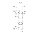
図1に示すように、仮設用支柱11は合金製の断面円形のパイプ部材であって、本体パイプ12の第1の端部としての上端部12Aの上端面12a及び第2の端部としての下端部12Bの下端面12bの面の連続方向は軸方向に対して直交している。上端面12aには先端方向に突出する半円形形状の一対の突起14が180度対向する位置に一体形成されている。下端面12bの前記突起14と同じ周方向位置においてやはり180度対向する位置には一対の半円形形状の切り欠き15が形成されている。突起14は仮設用支柱11を直列に連結する際に切り欠き15に嵌合されることとなる。本実施例では突起14の左右幅は12mmとされ、上下高さは10mmとされている。切り欠き15の左右幅は15mmとされ、上下高さは11.5mmとされている。つまり、切り欠き15は突起14外形よりも若干大きめに形成され嵌合時に若干の遊びがあるようになっている。これは製造誤差によって嵌合時に切り欠き15の内縁と突起14とが干渉して連結不能状態となることを避けるためである。
Hereinafter, a temporary support column (single tube column) which is an example of a column member for a temporary scaffold according to the present invention will be described with reference to the drawings.
As shown in FIG. 1, the
図1及び図4に示すように、本体パイプ12の上端部12には同本体パイプ12よりも一回り小さなサイズの第1の補助パイプ16が嵌挿固定されている。第1の補助パイプ16の上端側は本体パイプ12の上端面12aから所定量(本実施例では10mm)突出している。第1の補助パイプ16のこの突出した部分が段差部17とされている。段差部17の上端面17aはちょうど突起14の先端位置と一致する。
第1の補助パイプ16には連結ほぞ18が嵌挿固定されている。連結ほぞ18は先端が塞がれた断面円形形状のパイプ部材である。連結ほぞ18の基部寄り側面には180度対向する位置に固定ピン用の第1のピン穴19が形成されている。
本体パイプ12の下端部12Bには前記第1の補助パイプ16と同サイズの第2の補助パイプ20が嵌挿固定されている。内パイプとしての第2の補助パイプ20の下端面20aは本体パイプ12の下端面12bから所定量(本実施例では10mm)退避している。この退避量は段差部17の本体パイプ12の上端面12aからの突出量と一致する。第2の補助パイプ20の内周面と本体パイプ12の下端面12b寄りの内周面によってほぞ穴21が構成されている。本体パイプ12の下端面12bから所定距離をおいて180度対向する位置に固定ピン用の第2のピン穴32が形成されている。
As shown in FIGS. 1 and 4, a first
A connecting
A second
本体パイプ12の外周には長手方向に沿って所定間隔毎に緊結ポジション22が設けられている。本実施例では緊結ポジション22は4箇所に設けられているが、本体パイプ12の長さによって緊結ポジション22の数や位置を変更することは可能である。
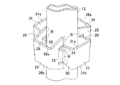
図2に示すように、緊結ポジション22は180度対向して同じ高さに配置された一対の第1の緊結ホルダー23と、両第1の緊結ホルダー23と同高さにおいて周方向に90度ずれて180度対向して同じ高さに配置される一対の第2の緊結ホルダー24とから構成されている。
図2、図3(a)に示すように、第1の緊結ホルダー23は左右一対の脚部プレート25と、同両脚部プレート25の外端側で同両脚部プレート25を連結する連結プレート26とから構成されている。脚部プレート25と連結プレート26は一枚の鋼板をコ字状に屈曲することによって一体的に構成されている。両脚部プレート25はその基端側で本体パイプ12に当接させられ溶着させられている。尚、溶着金属による肉盛り部分を図2上の図示ではBで表している。
脚部プレート25は本体パイプ12に対する溶着側(以下、この溶着側を本体側とする)ほど上下方向に幅広となるように構成されている。脚部プレート25は基端側が切り欠かれるとともに切り残された一部が外方に斜めに折り曲げられて補強プレート28が形成されている。補強プレート28が外方に折り曲げられた状態で上下の切り欠き溝27間には透孔29が形成されることとなる。透孔29は脚部プレート25が本体パイプ12に溶着された状態で本体パイプ12に隣接した位置に窓孔状となって配置されることとなる。連結プレート26は水平かつ互いに平行に延出された上下縁線26a,26bを備え、図1に示すように上側ほど外方に開くように傾斜させられている。
Tightening
As shown in FIG. 2, the
As shown in FIGS. 2 and 3A, the first binding
The
図2、図3(b)に示すように、第2の緊結ホルダー24は左右一対の脚部プレート30と、同両脚部プレート30の外端側で同両脚部プレート30を連結する連結プレート31とから構成されている。脚部プレート30と連結プレート31は一枚の鋼板をコ字状に屈曲することによって一体的に構成されている。両脚部プレート30はその基端側で本体パイプ12に当接させられ溶着させられている。脚部プレート30は本体側ほど上下方向に幅狭となるように構成されている。連結プレート31は水平かつ互いに平行に延出された上下縁線31a,31bを備え、上記第1の緊結ホルダー23側の連結プレート26と同様上側ほど外方に開くように傾斜させられている。連結プレート31は上記第1の緊結ホルダー23の連結プレート26と同形状とされている。
図2に示すように、第1及び第2の緊結ホルダー23,24が本体パイプ12に固着された状態で隣接する第1及び第2の緊結ホルダー23,24の脚部プレート25,30は互いに交叉して配置されている。すなわち、第2の緊結ホルダー24側の脚部プレート30の先端部30aが第1の緊結ホルダー23側の脚部プレート25の透孔29を介して第1の緊結ホルダー23に包囲された内側に進出した状態とされている。一方、第1の緊結ホルダー23の補強プレート28の先端は第2の緊結ホルダー24側の脚部プレート30の外壁面に対して溶着されている。
As shown in FIGS. 2 and 3B, the second
As shown in FIG. 2, the
次に、このように構成される仮設用支柱11の使用方法の一例について説明する。
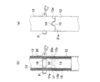
まず仮設用支柱11同士を直列に連結する場合について説明する。この場合には図5に示すように、下方の仮設用支柱11の連結ほぞ18を上方の仮設用支柱11のほぞ穴21を連結させることとなる。
下方の仮設用支柱11の連結ほぞ18を上方の仮設用支柱11のほぞ穴21に挿入すると連結ほぞ18の外周面が第2の補助パイプ20の内周面と接する。この接触状態で軸方向に両者を軸方向に相対的に接近させていくようにする。この時、突起14先端が第2の補助パイプ20の下端面20aと衝突しないように上方の仮設用支柱11の切り欠き15と下方の仮設用支柱11の突起14とを本体パイプ12の周方向において位置調整して両者を対向配置させた上で嵌合させる。突起14と切り欠き15との嵌合に伴って段差部17の外周面が本体パイプ12の下端面12b寄りの内周面と接していくこととなる。連結完了状態では上下本体パイプ12の上端面12aと下端面12bとが当接するとともに、段差部17の上端面17aと第2の補助パイプ20の下端面20aが当接することとなる。そして連結完了後にちょうど照合される第1及び第2のピン穴19,32に対して固定ピンPを挿通して連結した仮設用支柱11の抜け落ちを防止する。この時、上下の仮設用支柱11の各緊結ポジション22において第1の緊結ホルダー23と第2の緊結ホルダー24の向きは軸方向で一致する。
ここに、実施例の仮設用支柱11と同じ外径の本体パイプであってパイプ下縁に上記切り欠き15を有さず、上記連結ほぞ18よりも大径のほぞを有する従来型の仮設用支柱が混ざる場合を想定する。
そのような従来型の仮設用支柱に対して実施例の仮設用支柱11の連結ほぞ18を連結させる場合には連結ほぞ18は挿入可能ではあるものの、突起14が連結の邪魔となるので端部同士が当接できないため間違えて使用してしまうことはない。また、逆に従来型の仮設用支柱に対して従来型の仮設用支柱のほぞを連結させる場合には、ほぞがわずかに挿入された段階で第2の補助パイプ20に干渉してしまうため奥まで挿入することはできないこととなって、やはり間違えて使用してしまうことはない。
Next, an example of how to use the
First, a case in which the
When the connecting
Here, it is a main body pipe having the same outer diameter as that of the
In the case where the
次に例えば図8に示すように、仮設用支柱11と建枠40とが1つの仮設足場で混在して使用されるケースにおいて仮設用支柱11と建枠40とを連結する場合について説明する。尚、図8は仮設用支柱11と建枠40とを併用した一例であって、この図に示されるような足場板35、筋交い36、布材37、ベース金具38等の配置位置・数・形状はこれらに限定されるものではない。
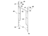
本実施例で使用される建枠40は、図6に示すように左右一対の脚柱パイプ41と両脚柱パイプ41を上端位置で連結する連結パイプ42とから基本的な骨格が構成されている。各脚柱パイプ41の内側面には補強フレーム43が配設されている。脚柱パイプ41は断面円形形状のパイプ部材であって、その外径は上記第2の補助パイプ20の内径と略一致し、その内径は連結ほぞ18の外径と略一致する。脚柱パイプ41の上下端部はそれぞれほぞ穴44とされる。脚柱パイプ41の上下端部寄りには第3のピン穴45が形成されている。
本実施例では上方に配置される仮設用支柱11と建枠40とを連結させる際には図6及び図7に示すコネクタ46を使用する。コネクタ46は建枠40のほぞの短さを補う部材である。コネクタ46は中央のリング部47を境界として上下にそれぞれ連結ほぞ48を形成した部材である。連結ほぞ48の外径は脚柱パイプ41の内径と略一致する。(つまりコネクタ46の連結ほぞ48は仮設用支柱11の連結ほぞ18と同径である)。コネクタ46の連結ほぞ48には使用時に前記第2及び第3のピン穴32,45と照合される第4のピン穴49が形成されている。リング部47は仮設用支柱11と脚柱パイプ41を連結する際に仮設用支柱11側の第2の補助パイプ20を受ける受けフランジとしての役割をする。リング部47の外径は脚柱パイプ41の外径と一致する。
Next, as shown in FIG. 8, for example, a case where the
As shown in FIG. 6, the
In this embodiment, the
まず、図9(a)に示すように建枠40の上方側に仮設用支柱11を連結する場合について説明する。
図7(a)に示すように、建枠40の脚柱パイプ41と仮設用支柱11の間にコネクタ46を配置し、図7(b)のようにコネクタ46の一方の連結ほぞ48をほぞ穴21に挿入する。但し、この場合に連結ほぞ48が嵌合されるのは第2の補助パイプ20のみである。他方の連結ほぞ48を脚柱パイプ41のほぞ穴44に挿入することで建枠40と仮設用支柱11は連結されることとなる。図7(c)に示すように、連結が完了した状態でコネクタ46はそのリング部47の上縁面47aが第2の補助パイプ20の下端面20aに当接し、リング部47の下縁面47bが脚柱パイプ41の上縁面41aに当接する。そして連結完了後に照合される第2及び第4のピン穴32,49と第2及び第3のピン穴32,45に対して固定ピンPを挿通する。
一方、図9(b)のように建枠40の下方側に仮設用支柱11を連結する場合では、コネクタ46を使用せず脚柱パイプ41の下端側ほぞ穴44に仮設用支柱11の連結ほぞ18を挿入する。連結完了状態では脚柱パイプ41の下縁面41bと段差部17の上端面17aとが当接する。上記と同様連結完了後に照合される第1及び第3のピン穴19,45に対して固定ピンPを挿通する。
First, the case where the
As shown in FIG. 7A, a
On the other hand, when the
上記のように構成することにより本実施例の仮設用支柱11は次のような効果が奏される。
(1)従来型の仮設用支柱が間違って本実施例の仮設用支柱11に連結されることはなく、一方、建枠40は本実施例の仮設用支柱11に連結することが可能であるので、種類の異なる柱部材から選択的に建枠40のみを本実施例の仮設用支柱11と一緒に併用でき、柱部材の使用価値が高まる。
(2)同種の仮設用支柱11を上下に連結する場合に突起14と切り欠き15とを嵌合させるだけで緊結ポジション22を構成する第1及び第2の緊結ホルダー23,24の向きを縦方向に揃えることができる。
(3)突起14先端は段差部17の上端面17aと一致するため、誤って連結した従来型の仮設用支柱のほぞ穴が段差部17上端面17aから先に進出することができず、段差部17に嵌合されてしまうことが防止されることとなる。
(4) 緊結ポジション22を構成する第1及び第2の緊結ホルダー23,17は第1及び第2の緊結ホルダー23,17は両者の脚部プレート25,25の形状は異なっても連結プレート26,26の形状と高さ方向の配置位置は同じとなるため、布材37を同高さに取り付けることができ、その結果布材37に架設される90度向きの異なる足場板35も同高さに配置することができ、コーナー部分での足場板の段差をなくすことができる。また、この結果、上記のように同じ足場で建枠40とともに使用することができる。
By configuring as described above, the
(1) The conventional temporary support column is not mistakenly connected to the
(2) When the same type of
(3) Since the tip end of the
(4) The first and
尚、この発明は、次のように変更して具体化することも可能である。
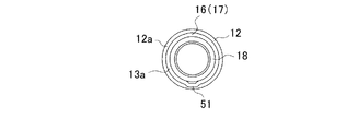
上記実施例では突起14を本体パイプ12の上端面12aに形成するようにしていたが、図11及び図12に示すように、段差部17の側面の一部、つまり第1の補助パイプ16の上部寄りの一部を本体パイプ12の外面(つら)と同程度に外方に膨出させて突起51とするようにしてもよい。このような構成でも上記と同様の効果が奏される。
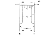
・上記実施例では建枠40の上方側に仮設用支柱11を連結する場合にはコネクタ46を配置するようにしていたが、図10のように建枠40の脚柱パイプ41にほぞ50と上記リング部47と同じ機能のリング部51(受けフランジ)を前もって形成するようにしても構わない。この場合ではほぞ穴44は脚柱パイプ41の下端のみに形成されることとなる。
・上記のような突起14と切り欠き15の形状やその数は一例であって、他の形状にしたり数を変更することは自由である。
・上記仮設用支柱11や建枠40の構成やサイズは一例であって、変更可能である。
・コネクタ46の構成は上記は一例である。
・本発明の仮設足場用の柱部材を仮設用支柱以外の柱部材に応用することも自由である。
・その他、本発明の趣旨を逸脱しない態様で実施することは自由である。
It should be noted that the present invention can be modified and embodied as follows.
In the above embodiment, the
In the above embodiment, when the
The shape and number of the
The configurations and sizes of the
The above configuration of the
-It is also free to apply the column member for the temporary scaffold of the present invention to a column member other than the temporary column.
-Besides, it is free to implement in a mode that does not depart from the gist of the present invention.
11…仮設足場用の柱部材としての仮設用支柱、14、51…突起、15…切り欠き、18…ほぞ、17…段差部、20…内パイプとしての第2の補助パイプ、21…ほぞ穴。
DESCRIPTION OF
Claims (5)
前記ほぞは前記本体パイプの外径よりも小径に構成され、同ほぞの同本体パイプ側基部には前記ほぞ穴の内径と略一致するとともに同ほぞよりも大径の外径を有する段差部が形成され、前記第1の端部の端面には同段差部方向に突出し、かつ少なくとも前記ほぞの外周位置まで進出することのない突起が形成され、
前記ほぞ穴には前記ほぞの外径に略一致する内径の内パイプが前記第2の端部の端面位置から前記段差部の高さ分退避した位置に自身の端面が配置されるように嵌挿され、同第2の端部側端面には前記突起が嵌合される切り欠きが形成されることを特徴とする仮設足場用の柱部材。 Tenons and mortises are formed at the first and second ends of both ends of the main pipe, and are connected in series to the same or other types of temporary scaffolding column members via the tenon or mortise. The column member for constructing a columnar structure in the vertical direction by being,
The tenon is configured to have a smaller diameter than the outer diameter of the main pipe, and the main pipe side base of the tenon has a stepped portion that substantially matches the inner diameter of the tenon hole and has a larger outer diameter than the tenon. Formed on the end surface of the first end portion is formed with a protrusion that protrudes in the direction of the stepped portion and does not advance at least to the outer peripheral position of the tenon,
An inner pipe having an inner diameter substantially matching the outer diameter of the tenon is fitted in the tenon so that the end face of the inner pipe is disposed at a position retracted from the end face position of the second end portion by the height of the stepped portion. A pillar member for a temporary scaffold, wherein a notch into which the protrusion is fitted is formed on the end surface on the second end side.
前記ほぞは前記本体パイプの外径よりも小径に構成され、同ほぞの同本体パイプ側基部には前記ほぞ穴の内径と略一致するとともに同ほぞよりも大径の外径を有する段差部が形成され、同段差部の外周の一部には外方に突出する突起が形成され、前記ほぞ穴には前記ほぞの外径に略一致する内径の内パイプが前記第2の端部の端面位置から前記段差部の高さ分退避した位置に自身の端面が配置されるように嵌挿され、同第2の端部側端面には前記突起が嵌合される切り欠きが形成されることを特徴とする仮設足場用の柱部材。 Tenons and mortises are formed at the first and second ends of both ends of the main pipe, and are connected in series to the same or other types of temporary scaffolding column members via the tenon or mortise. The column member for constructing a columnar structure in the vertical direction by being,
The tenon is configured to have a smaller diameter than the outer diameter of the main pipe, and the main pipe side base of the tenon has a stepped portion that substantially matches the inner diameter of the tenon hole and has a larger outer diameter than the tenon. A protrusion projecting outward is formed on a part of the outer periphery of the stepped portion, and an inner pipe having an inner diameter substantially matching the outer diameter of the tenon is formed in the tenon end surface of the second end portion A notch into which the projection is fitted is formed on the second end portion side end surface so that the end surface thereof is disposed at a position retracted from the position by the height of the stepped portion. A pillar member for a temporary scaffold characterized by the above.
前記両緊結ホルダーは前記本体パイプの長手方向に沿って溶着される左右一対の脚部プレートと、同両脚部プレートの外端側で同両脚部プレートを連結する連結プレートとから構成され、
前記第1の緊結ホルダーの前記脚部プレートは前記本体パイプ側ほど上下方向に幅広とされるとともに前記本体パイプ側と接する一部を含む領域に内外を連通する透孔を形成するとともに、前記第2の緊結ホルダーの前記脚部プレートは前記本体パイプ側ほど上下方向に幅狭とされ、
前記第2の緊結ホルダーの前記脚部プレートは前記第1の緊結ホルダーの前記脚部プレートに形成された前記透孔内に挿入され、平面視において交叉状に配置されるとともに、四方の前記緊結ホルダーの前記連結プレートの上縁が略同一水平面上に配置されていることを特徴とする請求項1〜3のいずれかに記載の仮設足場用の柱部材。 A pair of first tightening holders arranged at the same height facing each other in the circumferential direction of the main pipe, and opposed to each other at the same height as the first tightening holders by 90 degrees in the circumferential direction. And a tightening position comprising a pair of second tightening holders arranged at the same height,
The two fastening holders are composed of a pair of left and right leg plates that are welded along the longitudinal direction of the main body pipe, and a connecting plate that connects the leg plates on the outer end side of the leg plates.
The leg plate of the first tightening holder is wider in the vertical direction toward the body pipe side, and has a through hole communicating with the inside and outside in a region including a part in contact with the body pipe side. The leg plate of the binding holder of 2 is narrower in the vertical direction toward the body pipe side,
The leg plate of the second binding holder is inserted into the through hole formed in the leg plate of the first binding holder, and is arranged in a cross shape in a plan view. The column member for a temporary scaffold according to any one of claims 1 to 3, wherein an upper edge of the connection plate of the holder is disposed on substantially the same horizontal plane.
Priority Applications (1)
| Application Number | Priority Date | Filing Date | Title |
|---|---|---|---|
| JP2008303528A JP5128445B2 (en) | 2008-05-21 | 2008-11-28 | Column member for temporary scaffold |
Applications Claiming Priority (3)
| Application Number | Priority Date | Filing Date | Title |
|---|---|---|---|
| JP2008132789 | 2008-05-21 | ||
| JP2008132789 | 2008-05-21 | ||
| JP2008303528A JP5128445B2 (en) | 2008-05-21 | 2008-11-28 | Column member for temporary scaffold |
Publications (2)
| Publication Number | Publication Date |
|---|---|
| JP2010001725A JP2010001725A (en) | 2010-01-07 |
| JP5128445B2 true JP5128445B2 (en) | 2013-01-23 |
Family
ID=41583654
Family Applications (1)
| Application Number | Title | Priority Date | Filing Date |
|---|---|---|---|
| JP2008303528A Active JP5128445B2 (en) | 2008-05-21 | 2008-11-28 | Column member for temporary scaffold |
Country Status (1)
| Country | Link |
|---|---|
| JP (1) | JP5128445B2 (en) |
Families Citing this family (1)
| Publication number | Priority date | Publication date | Assignee | Title |
|---|---|---|---|---|
| DE102018109386A1 (en) * | 2018-04-19 | 2019-10-24 | Altrad Plettac Assco Gmbh | Reduction sleeve, pipe connector, connection system, scaffolding component, scaffolding system and method for producing a scaffolding component |
-
2008
- 2008-11-28 JP JP2008303528A patent/JP5128445B2/en active Active
Also Published As
| Publication number | Publication date |
|---|---|
| JP2010001725A (en) | 2010-01-07 |
Similar Documents
| Publication | Publication Date | Title |
|---|---|---|
| JP5904668B2 (en) | Temporary scaffolding materials | |
| JP5128446B2 (en) | Column member for temporary scaffold | |
| JP5128445B2 (en) | Column member for temporary scaffold | |
| JP2008169668A (en) | Foundation reinforcement unit, foundation reinforcement structure and coupling implement of foundation reinforcement | |
| JP2005248699A (en) | Tool for assembling column reinforcing bar | |
| JP4934483B2 (en) | Bracket for temporary scaffold | |
| JP6784712B2 (en) | Posts for temporary scaffolding | |
| JP3201716U (en) | Temporary scaffolding materials | |
| KR20180046603A (en) | Holding member for scaffold and scaffold using it | |
| JP2017203375A (en) | Strut for wedge-tight scaffold and strut structure using the same | |
| JP3143339U (en) | Scaffold auxiliary material mounting bracket | |
| JP2006169883A (en) | Temporary construction member and joint for temporary construction member | |
| JP5042796B2 (en) | Independent pillar for steel house, steel house using the same, and panel method | |
| JP4918521B2 (en) | Temporary strut and method for manufacturing the same | |
| JP7231925B2 (en) | Connection structure for temporary scaffolding | |
| WO2021245736A1 (en) | Joining hardware | |
| JP2017025537A (en) | Member for temporary scaffold | |
| JP6746551B2 (en) | Temporary scaffolding | |
| JP2013083121A (en) | Metal fitting | |
| JP2016169577A (en) | Preceding handrail with brace for curved surface | |
| JP2019173549A (en) | Member for temporary scaffold | |
| JP2016079758A (en) | Support post socket for scaffold used in construction work | |
| JP7194435B2 (en) | Structure of temporary scaffolding and connecting fittings used therefor | |
| JP2019060103A (en) | Pipe connecting tool | |
| JP6729881B2 (en) | Binding device on scaffolding |
Legal Events
| Date | Code | Title | Description |
|---|---|---|---|
| A621 | Written request for application examination |
Free format text: JAPANESE INTERMEDIATE CODE: A621 Effective date: 20110617 |
|
| A977 | Report on retrieval |
Free format text: JAPANESE INTERMEDIATE CODE: A971007 Effective date: 20121017 |
|
| TRDD | Decision of grant or rejection written | ||
| A01 | Written decision to grant a patent or to grant a registration (utility model) |
Free format text: JAPANESE INTERMEDIATE CODE: A01 Effective date: 20121019 |
|
| A01 | Written decision to grant a patent or to grant a registration (utility model) |
Free format text: JAPANESE INTERMEDIATE CODE: A01 |
|
| A61 | First payment of annual fees (during grant procedure) |
Free format text: JAPANESE INTERMEDIATE CODE: A61 Effective date: 20121031 |
|
| R150 | Certificate of patent or registration of utility model |
Free format text: JAPANESE INTERMEDIATE CODE: R150 Ref document number: 5128445 Country of ref document: JP Free format text: JAPANESE INTERMEDIATE CODE: R150 |
|
| FPAY | Renewal fee payment (event date is renewal date of database) |
Free format text: PAYMENT UNTIL: 20151109 Year of fee payment: 3 |
|
| R250 | Receipt of annual fees |
Free format text: JAPANESE INTERMEDIATE CODE: R250 |
|
| R250 | Receipt of annual fees |
Free format text: JAPANESE INTERMEDIATE CODE: R250 |
|
| R250 | Receipt of annual fees |
Free format text: JAPANESE INTERMEDIATE CODE: R250 |