JP5124720B2 - Shoulder pain relief device - Google Patents
Shoulder pain relief device Download PDFInfo
- Publication number
- JP5124720B2 JP5124720B2 JP2007308031A JP2007308031A JP5124720B2 JP 5124720 B2 JP5124720 B2 JP 5124720B2 JP 2007308031 A JP2007308031 A JP 2007308031A JP 2007308031 A JP2007308031 A JP 2007308031A JP 5124720 B2 JP5124720 B2 JP 5124720B2
- Authority
- JP
- Japan
- Prior art keywords
- upper arm
- shoulder pain
- rotator cuff
- shoulder
- hook
- Prior art date
- Legal status (The legal status is an assumption and is not a legal conclusion. Google has not performed a legal analysis and makes no representation as to the accuracy of the status listed.)
- Active
Links
Images


Description
本発明は、肩関節腱板断裂患者のための肩痛緩和装具に関する。The present invention relates to a shoulder pain relieving brace for the shoulder joint cuff tear patient.
通常、肩関節腱板を断裂乃至損傷した者は極度の肩痛に見舞われる。肩痛は、日常の座位、歩行時は勿論ながら、特に、夜間においては顕著に現れ、睡眠の妨げとなることが知られている。 Usually, a person who has torn or damaged a shoulder joint rotator cuff will experience extreme shoulder pain. It is known that shoulder pain appears prominently at night as well as during daily sitting and walking, and disturbs sleep.
こうした問題を解決するために、種々の装具乃至治療器具が提案されているが、一般的には、古くから用いられている肩枕がある。このような肩枕は、専らクッション機能を利用するもので、大きな効果は得られなかった。 In order to solve these problems, various appliances or treatment instruments have been proposed, but generally there are shoulder pillows that have been used for a long time. Such a shoulder pillow exclusively uses the cushion function, and a great effect cannot be obtained.
また、肩痛を軽減するのに効果的な装具として、更に種々の提案がなされているが、例えば、次の技術が挙げられる。
上記の引用文献1によれば、夜間における肩痛の原因を究明し、仰臥位にあっては、重力が肩関節に作用し、その患者の肩部が下垂して肩関節が伸展し、収縮を強いられることが原因であると見られている。 According to the above cited
そこで、対策として、仰臥時に肩の下側にブロック状の部材を当てがい、肩関節が下垂しないようにすることを考え、且つ、このようなブロック状の部材が寝返りをうっても肩から外れないようにするために、肩覆い部材に固定させるようにしたものである。 Therefore, as a countermeasure, consider putting a block-shaped member on the underside of the shoulder when supine to prevent the shoulder joint from drooping, and even if such a block-shaped member rolls over, it comes off the shoulder. In order to prevent this, it is fixed to the shoulder covering member.
こうした装具によって、従来の専らクッション効果を狙った肩枕では得られなかった効果的な肩痛軽減作用が期待できるようになったが、対象が、肩関節腱板を断裂乃至損傷した者ということで、比較的その目的が達成できたものと見られる。
何故なら、施術により腱板の縫合手術を行った患者に対してこの装具を実施したところ、夜間(昼も)の肩痛が思った程に軽減されないことが報告された。With these braces, it has become possible to expect an effective shoulder pain reduction effect that could not be obtained with conventional shoulder pillows aimed solely at the cushion effect, but the subject was a person who had torn or damaged the shoulder joint rotator cuff It seems that the purpose was relatively achieved.
It was reported that when this brace was performed on a patient who had a rotator cuff suture operation, the shoulder pain at night (noon) was not reduced as much as expected.
こうした事態は、肩関節腱板の損傷患者が、大別して、損傷乃至断裂がそのままである場合と、施術により腱板の縫合手術を行い、その後にリハビリを行っている場合の2つの態様が考えられ、それぞれの状態において肩痛発生のメカニズムに差異があることが原因ではないかと考えられる。
即ち、推測するに、施術により腱板の縫合手術を行うと、腱板が従前よりも短くなり、自然の状態(筋肉の弛緩状態)で、肩関節における肩と腕との相対位置が変わること、即ち、肩関節の水平屈曲が寧ろ自然な状態になり、健常者の肩関節とは異なる状態にあることが原因ではないかと考えられるのである。There are two modes for this situation: patients with shoulder joint rotator cuff injury can be broadly divided into cases in which the damage or tear remains intact, and rotator cuff sutures are performed by surgery, followed by rehabilitation. It is thought that this is due to the difference in the mechanism of shoulder pain in each state.
In other words, it is speculated that when the rotator cuff is sutured by surgery, the rotator cuff becomes shorter than before, and the relative position of the shoulder and arm in the shoulder joint changes in the natural state (muscle relaxed state). That is, it is considered that the horizontal bending of the shoulder joint is in a natural state rather than being in a state different from that of a healthy person.
このように施術により腱板の縫合手術を行った場合、肩関節における肩と腕との相対位置が変わって、肩関節の水平屈曲が進行する結果、前述の肩関節の下垂の程度が大きく成ることが想定できる。このように肩関節の下垂が大きくなる場合に、単に肩関節の下垂を抑えるだけであるなら、上述のブロック状の部材の位置を変えたり、大きさを変えたりすることで容易に対処可能であり、また、そのように実際に行われてきたものである。
しかし乍ら、実際には、こうした対処方法を施しても、肩痛が大幅に改善されるということはなかったのである。When the rotator cuff is sutured in this manner, the relative position between the shoulder and the arm in the shoulder joint changes, and as a result of the horizontal flexion of the shoulder joint, the degree of drooping of the shoulder joint increases. Can be assumed. If the shoulder joint droops in this way, if it is simply to suppress the drooping of the shoulder joint, it can be easily handled by changing the position or size of the block-shaped member described above. Yes, and it has actually been done that way.
However, in fact, this treatment did not significantly improve shoulder pain.
本発明は、かかる問題点に鑑み、肩関節腱板断裂患者の肩痛を効果的に軽減できようにすることを目的とする。In view of the above problems, and an object thereof is to make possible to effectively reduce the shoulder joint cuff tears patient's shoulders pain.
本発明にかかる肩痛緩和装具は、上記課題を解決するために、請求項1に記載の通り、肩関節腱板断裂患者のための肩痛緩和装具であって、
上腕を所定の外転角で保持して腱板を弛緩させるように上腕と身体側部との間に位置される本体部材(1)と、
前記本体部材(1)を身体に取り付ける取り付け手段(2)と、
上腕に巻回保持され、係止手段(3)を備えた上腕用保持部材(4)とからなり、
前記本体部材(1)は、バッグ状に構成され、内部に体積を可変できる充填部材(11)を備え、該充填部材(11)がキャップ(11A)を備えたエアバッグで構成され、エアの充填量によって体積を可変できるように構成されており、
前記上腕用保持部材(4)に、患者の上腕の腋下の開度姿勢を安定させる腋下部材(6)が備えられ、且つ、該腋下部材(6)が前記本体部材(1)に係脱自 在に設けられている、
ことを特徴とする。Shoulder pain relieving orthosis according to the present invention, in order to solve the above problems, as described in
A body member (1) positioned between the upper arm and the body side so as to relax the rotator cuff while holding the upper arm at a predetermined abduction angle;
Attachment means (2) for attaching the body member (1) to the body;
The upper arm holding member (4) which is wound around the upper arm and has locking means (3) ,
The main body member (1) is configured in a bag shape and includes a filling member (11) whose volume can be changed inside. The filling member (11) is configured by an airbag including a cap (11A). It is configured so that the volume can be changed according to the filling amount,
The upper arm holding member (4) is provided with an arm member (6) for stabilizing the arm position of the patient's upper arm, and the arm member (6) is attached to the main body member (1). is provided in the disengaged self standing,
It is characterized by that.
本発明において、肩関節腱板断裂患者とは、肩関節腱板断裂を手術によって回復させられた者で、術後のリハビリを受ける状態にある患者である。In the present invention, the shoulder joint cuff tears patient, a person who has been allowed to recover by surgery shoulder joint cuff tear, a patient who is in a state to receive a postoperative rehabilitation.
本発明によれば、上腕と身体側部との間に位置される本体部材、そして、上腕用保持部材及び腋下部材によって上腕を所定の外転角で保持すること、特に、キャップを備えたエアバッグで構成された充填部材によって、上腕の保持外転角を、エアの吹き込み量を調整するだけで、大きな角度範囲において、容易に所要の角度に無段階に調節して適正に腱板を弛緩させ、以って、肩関節腱板の全体の有効な弛緩状態が得られて肩痛が軽減されるに至ったものである。これは、上腕を所定の外転角で保持することにより、損傷腱板に対する肩甲下筋、棘上筋、棘下筋、小円筋の弛緩状態のバランスが図れる結果によるものと考えられる。 According to the present invention, the main body member positioned between the upper arm and the body side part , and the upper arm is held at a predetermined abduction angle by the upper arm holding member and the armpit member , in particular, the cap is provided. With a filling member composed of an air bag, the abduction angle of the upper arm can be easily adjusted steplessly to the required angle in a large angle range by simply adjusting the amount of air blown, and the rotator cuff can be properly adjusted. It is relaxed, so that an effective relaxation state of the entire shoulder joint rotator cuff is obtained and shoulder pain is reduced. This is considered to be due to the result that the balance of the relaxed state of the subscapular muscle, the supraspinatus, the subspinous muscle, and the small circular muscle with respect to the damaged rotator cuff can be achieved by holding the upper arm at a predetermined abduction angle.
そして、腱板緊張緩和部材を備える場合には、該腱板緊張緩和部材が上腕用保持部材に対して係止されるものであるので、上腕用保持部材の上腕に対する装着位置の調節或いは上腕用保持部材に対する腱板緊張緩和部材の係止位置の調節によって、肩甲骨に対する腱板緊張緩和部材の位置を調節可能とすることができて、上述の上腕を所定の外転角で保持することと相まって、仰臥姿勢においても、適正、且つ有効な腱板緊張緩和状態を得られ、肩痛緩和を一層効果的に達成できる。
本発明のその他利点は、以下の記載から明らかとなろう。When the rotator cuff tension reducing member is provided , the rotator cuff tension reducing member is locked to the upper arm holding member. By adjusting the locking position of the rotator cuff tension relief member with respect to the holding member, the position of the rotator cuff tension relief member relative to the scapula can be adjusted, and the above-mentioned upper arm is held at a predetermined abduction angle; In combination, a proper and effective rotator cuff relaxation state can be obtained even in a supine posture , and shoulder pain can be alleviated more effectively.
Other advantages of the present invention will become apparent from the following description.
本発明の実施に際しては、前記本体部材1が、バッグ状に構成され、内部に体積を可変できる充填部材11を備えていることが好ましい。
このように構成することで、本体部材1の体積を可変でき、各患者の身体の大きさ及び異なる腱板の状態(施術による収縮度)に合わせた上腕の適正な外転角を容易に調節することができる。この外転角(身体側部に対する上腕の開き角度)としては、術後直後であれば、好ましくは80度であるが、暫時リハビリにより、80度から30度の範囲に減少させるように調整されることになる。In carrying out the present invention, it is preferable that the
With this configuration, the volume of the
また、前記充填部材11がエアバッグで構成され、エアの充填量によって体積を可変できるように構成されていることが好ましい。
このように構成することで、前記充填部材11の体積の調節がエアの吹き込み量を調節するだけで簡単に行い得る。Moreover, it is preferable that the said filling
With this configuration, the volume of the
更に、前記上腕用保持部材4に、患者の上腕の腋下の開度姿勢を安定させる腋下部材6が備えられ、且つ、該腋下部材6が前記本体部材1に係脱自在に設けられているのが好ましい。
このように、腋下部材6を備え、これを前記上腕用保持部材4と本体部材1とで固定することで、患者の上腕と身体との開度姿勢(角度)をより一層安定保持させることができ、腱板の弛緩状態が維持され易くなる。Further, the upper
As described above, the
また、前記上腕用保持部材4の係止手段3が第1の面ファスナー3Aで構成され、前記腱板緊張緩和部材5に該第1の面ファスナー3Aに係合する第2の面ファスナー5Aが備えられているのが好ましい。このような面ファスナーについては、面ファスナーとファスナーとの組み合わせ、通常のファスナーに代えてもよい。
このような第1、第2の面ファスナー3A,5Aを用いることで、ワンタッチで腱板緊張緩和部材5を装着でき、また、そのファスナーの有効範囲内で装着位置を微調整でき、各患者に対する適正位置での装着が容易に行い得る。Further, the locking means 3 of the upper
By using such first and second hook-and-
更に、前記腋下部材6に第3の面ファスナー6Aが備えられ、前記本体部材1に第4の面ファスナー1Cが備えられ、両者が係脱自在とされているのが好ましい。
このように、第3、第4の面ファスナー6A,1Cを用いることによって腋下部材6の装着を容易に行い得ると共にそのファスナーの有効範囲内で装着位置を微調整できる。Furthermore, it is preferable that the
Thus, by using the third and fourth hook-and-loop fasteners 6A and 1C, the
また、前記腋下部材6と前記上腕用保持部材4とが一体に構成されているのが好ましい。
このように構成することで、前記上腕用保持部材4を上腕に巻回固定することで、自動的に前記腋下部材6が腋下に位置されることとなり、装着が簡便に行い得る。
勿論、前記上腕用保持部材4と前記腋下部材6とを別体とし、両者を面ファスナーで係脱させるようにしてもよい。Moreover, it is preferable that the said
By configuring in this way, the
Of course, the upper
更に、前記取り付け手段2が、身体に巻回され、長さ調節が自在のベルト状体2Aで構成されているのが好ましい。
このように、長さ調節が自在のベルト状体2Aを用いることで、身体にたいする装着状態を任意に調節できて便利である。Furthermore, it is preferable that the attachment means 2 is constituted by a belt-
Thus, by using the belt-
本発明にかかる肩関節腱板断裂患者のための肩痛緩和装具の実施の形態を、図面を参照して以下詳述する。
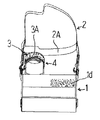
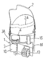
図1乃至図4は、前腕保持部材13と腱板緊張緩和部材5を外した状態を示し、図5乃至図8は、前腕保持部材13は装着し、腱板緊張緩和部材5を外した状態を示す。
本発明にかかる肩痛緩和装具は、上腕10を所定の外転角で保持して腱板を弛緩させるように上腕と身体側部との間に位置される本体部材1、前記本体部材1を身体に取り付ける取り付け手段2、上腕10に巻回保持され、係止手段3を備えた上腕用保持部材4、及び前記係止手段3に係脱自在に係止され、患者の仰臥時に腱板の緊張を緩和する状態に肩甲骨を支持する腱板緊張緩和部材5からなる。An embodiment of shoulder pain relieving brace for the shoulder joint cuff tears patient according to the present invention will be described in detail hereinafter with reference to the accompanying drawings.
1 to 4 show a state in which the
The shoulder pain relief device according to the present invention includes a
ここで、本体部材1について説明する。
この本体部材1は、図1乃至図8に示すように、開閉蓋1Dを備えたバッグ状(合成繊維織布の縫製)に構成され、内部に体積を可変できる充填部材11を備えている。このように構成することで、本体部材1の体積を可変でき、各患者の身体の大きさ及び異なる腱板の状態(施術による収縮度)に合わせた上腕の適正な外転角を容易に調節することができる。
そして、この実施例では、前記充填部材11は、キャップ11Aを備えたエアバッグで構成され、エアの充填量によって体積を可変できるように構成されている。この充填部材11の体積が変わると、腕の外転角が変わることになる。Here, the
As shown in FIGS. 1 to 8, the
In this embodiment, the filling
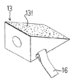
更に、図13に示すように、この本体部材1には、その外側部に、補助収容部1Eが備えられ、内部に別の充填材12が、所要の嵩になるように折り畳まれ、所要の体積を形成し収納されている。この充填材12としては、保形成のあるシート、ここではエアーキャップ(商標名)(クッション効果を目的として小気泡が所定の間隔で配置された合成樹脂製のシート)が用いられ、これが所定の嵩になるように折畳まれて収容される。これらの充填部材11及び充填材12は、前記開閉蓋1Dが被せられることで本体部材1の内に被覆され、この開閉蓋1Dを開けることで、取出しが可能となる。これらの充填部材11及び充填材12の嵩を調節することで、腕の外転角を適正角度に調整できる。Further, as shown in FIG. 13, the
また、図1乃至図8及び図13、図14乃至図16示すように、本体部材1は、前記本体部材1を身体に取り付ける取り付け手段2、即ち、身体に巻回され、長さ調節が自在のベルト状体2Aを備えている。
このベルト状体2Aは、治癒腱板とは反対側の肩と身体側部に巻回されるもので、図示の如く、通常の肩掛けバッグ或いはリュックサックのように、バックルを備えていて、装着時の長さを調節できるタイプのものである。
しかし、ベルト状体2の巻回方法については、どのような形態を採用しても差し支えないものであり、また、ベルトの本数、構造についても適宜選択できる。Further, as shown in FIGS. 1 to 8, 13, and 14 to 16, the
This belt-
However, the winding method of the belt-
更に、この本体部材1には、前腕保持部材13が備えられる。
この前腕保持部材13は、本体部材1の一部、ここでは開閉蓋1Dに備えた第6の面ファスナー1dに対して、この前腕保持部材13に備えた第7の面ファスナー16を係脱させることで、所望の位置に装着できる。この前腕保持部材13に手首部を固定することで、腱板が弛緩する状態に、腕を所定の外旋角で固定する。Further, the
The
この開閉蓋1Dは、前記本体部材1の補助収容部1Eに前記充填材12を収容した状態にあっては、図6に示すように、略全体が上向きとなり、前記前腕保持部材13も上向き状態に位置され、ここに前腕14が肘関節から上方に曲げられた状態で固定されることになる。
この前腕保持部材13は、外形が三角柱の台座部13Dを備え、手首側が広幅の底辺側となるように、即ち、該台座部13Dに前腕を載せたときに手首側が肘よりも上方に位置するように前記本体部材1に装着され、前腕14の位置を所望の位置に選択的に固定することで、腱板に対する負荷を更に軽減できるようにされている。図示において、13eは、手首を止める面ファスナータイプのベルト状体である。図9及び図10の13fは、台座部13Dの上面の面ファスナーを示す。 In the state where the
The
次に、上腕10に巻回保持され、係止手段3を備えた上腕用保持部材4について説明する。
この上腕用保持部材4は、帯状体で構成され、そこに係止手段3としての第1の面ファスナー3Aが備えられている。この係止手段3としては、その他に、適宜の位置に複数個配置したホックの如き係止手段としてもよい。
従って、帯状体を用いることで、上腕10の任意の位置に装着して固定することができるものである。
そして、前記上腕用保持部材4は、後述の腋下部材6と一体に構成されており、ここでは、この上腕用保持部材4の帯状体が、腋下部材6に一体逢着されている。Next, the upper
The upper
Therefore, by using a belt-like body, it can be mounted and fixed at an arbitrary position of the
The upper
次に、腱板緊張緩和部材5について、図11及び図12、その他の図面に基づいて説明する。この腱板緊張緩和部材5は、外形が三角柱(正面視で直角三角形)を成し、内部に保形性の充填物(ここではエアーキャップ(商標名))を挿入した袋状体で構成されている。この腱板緊張緩和部材5は、その大きさを調節した状態で仰臥状体の患者の肩甲骨に当てられるように設置されることになる。即ち、図14に示す如く、その三角柱の鋭角先端側が脊椎側に向き、厚みのある底辺側が上腕10側にくるように位置されるのである。Next, the rotator cuff
そして、前記上腕用保持部材4の係止手段3が、上述のように第1の面ファスナー3Aで構成されているので、前記腱板緊張緩和部材5に該第1の面ファスナー3Aに係合する第2の面ファスナー5Aが備えることで、両者を所定の範囲内の位置で係脱自在に装着することができる。 Since the locking means 3 of the upper
更に、前記本体部材1には、患者の上腕の腋下の開度姿勢を安定させる腋下部材6を係脱自在に設けてある。この腋下部材6は、上述の通り、その帯状体が前記上腕用保持部材4に一体逢着されている。
そして、前記腋下部材6に第3の面ファスナー6Aが備えられ、前記本体部材1に第4の面ファスナー1Cが備えられ、両者が係脱自在とされている。
この腋下部材6も、外形は、三角柱を成し、その角部が腋下に接当されるように位置される。Further, wherein the
The
The
図14は、肩痛緩和装具の仰臥姿勢での使用状態を示し、この本体部材1を身体に装着した状態で、上腕保持部6Bに腱板緊張緩和部材5が、その傾斜面の所望の位置(肩痛緩和位置)で係止されている。即ち、腱板緊張緩和部材5の上腕下方への挿入位置は、任意に選定できるもので、その三角形の傾斜面により、上腕を支持するに適した支持状態を得ることができる。この際、腱板緊張緩和部材5が必ずしも肩甲骨の下方に達する必要性ない。要するに上腕の肩関節及び上腕の下垂が防げればよい。
上記腱板緊張緩和部材5が一旦上腕保持部6Bに係止されれば、上腕保持部6Bが一体の腋下部材6を介して本体部材1に固定されることになり、本体部材1が身体に固定されているものであるから、全体として、上記腱板緊張緩和部材5の位置が固定されることになる。FIG. 14 shows a use state of the shoulder pain relief device in a supine posture, and with the
Once the rotator cuff
図15は、歩行姿勢での使用状態を示し、ここでは、施術直後のリハビリとして、本体部材1の補助収容部1Eに充填材12が充填されて、本体部材1が嵩の高い状態とされ、前腕保持部が本体部材1の上面に位置された状態となって、ここに所定の外旋角度で前腕14が固定される。このようにすると、リハビリにより肩の可動範囲を広げ易くなる。
また、図16は、同様の歩行姿勢での使用状態を示すが、ここでは、施術暫くしてリハビリが進行した状態での使用状態を示す。従って、本体部材1の補助収容部1Eから充填材12が除去され、本体部材1が嵩の低い状態とされ、前腕保持部が本体部材1の横側面に位置された状態となって、ここに前腕14が固定される。FIG. 15 shows a use state in a walking posture, and here, as rehabilitation immediately after the treatment, the auxiliary
Moreover, FIG. 16 shows the use state in the same walking posture, but here shows the use state in a state where rehabilitation has progressed for a while after the treatment. Accordingly, the
(腋下部材の一部変形例)
上記実施例では、図9等に示すように、前記腋下部材6に上腕保持部6Bが一体的に備えられているが、腋下部材6と上腕保持部6Bとを別体とし、夫々を面ファスナーで係脱させる構成としてもよい。換言すると、要するに、上腕保持部6Bが少なくとも腱板緊張緩和部材5を所要の姿勢で係止できればよいものである。(Partial modification of the armpit member)
In the above embodiment, as shown in FIG. 9 and the like, the
本発明の肩痛緩和装具は、肩関節腱板断裂患者のための肩痛に有効であるが、その他に、手術を施していない患者に対しても有効であり、その応用範囲は広いものである。Shoulder pain relieving orthosis of the present invention is effective for shoulder pain for the shoulder joint cuff tears patient Other also effective for patients not subjected to surgery, its application range than wide ones is there.
1:本体部材
1C:第4の面ファスナー
2:取り付け手段
2A:ベルト状体
3:係止手段
3A:第1の面ファスナー
4:上腕用保持部材
5:腱板緊張緩和部材
5A:第2の面ファスナー
6:腋下部材
6A:第3の面ファスナー
6B:上腕保持部
6C:第5の面ファスナー
11:充填部材1: Main body member 1C: Fourth hook-and-loop fastener 2: Attachment means 2A: Belt-like body 3: Locking means 3A: First hook-and-loop fastener 4: Upper arm holding member 5: Rotator cuff
Claims (6)
上腕を所定の外転角で保持して腱板を弛緩させるように上腕と身体側部との間に位置される本体部材(1)と、
前記本体部材(1)を身体に取り付ける取り付け手段(2)と、
上腕に巻回保持され、係止手段(3)を備えた上腕用保持部材(4)とからなり、
前記本体部材(1)は、バッグ状に構成され、内部に体積を可変できる充填部材(11)を備え、該充填部材(11)がキャップ(11A)を備えたエアバッグで構成され、エアの充填量によって体積を可変できるように構成されており、
前記上腕用保持部材(4)に、患者の上腕の腋下の開度姿勢を安定させる腋下部材(6)が備えられ、且つ、該腋下部材(6)が前記本体部材(1)に係脱自 在に設けられている、
ことを特徴とする肩痛緩和装具。A shoulder pain relieving brace for the shoulder joint cuff tear patient,
A body member (1) positioned between the upper arm and the body side so as to relax the rotator cuff while holding the upper arm at a predetermined abduction angle;
Attachment means (2) for attaching the body member (1) to the body;
The upper arm holding member (4) which is wound around the upper arm and has locking means (3) ,
The main body member (1) is configured in a bag shape and includes a filling member (11) whose volume can be changed inside. The filling member (11) is configured by an airbag including a cap (11A). It is configured so that the volume can be changed according to the filling amount,
The upper arm holding member (4) is provided with an arm member (6) for stabilizing the arm position of the patient's upper arm, and the arm member (6) is attached to the main body member (1). is provided in the disengaged self standing,
Shoulder pain relief device characterized by that.
Priority Applications (1)
| Application Number | Priority Date | Filing Date | Title |
|---|---|---|---|
| JP2007308031A JP5124720B2 (en) | 2007-10-30 | 2007-10-30 | Shoulder pain relief device |
Applications Claiming Priority (1)
| Application Number | Priority Date | Filing Date | Title |
|---|---|---|---|
| JP2007308031A JP5124720B2 (en) | 2007-10-30 | 2007-10-30 | Shoulder pain relief device |
Publications (2)
| Publication Number | Publication Date |
|---|---|
| JP2009106716A JP2009106716A (en) | 2009-05-21 |
| JP5124720B2 true JP5124720B2 (en) | 2013-01-23 |
Family
ID=40775905
Family Applications (1)
| Application Number | Title | Priority Date | Filing Date |
|---|---|---|---|
| JP2007308031A Active JP5124720B2 (en) | 2007-10-30 | 2007-10-30 | Shoulder pain relief device |
Country Status (1)
| Country | Link |
|---|---|
| JP (1) | JP5124720B2 (en) |
Families Citing this family (4)
| Publication number | Priority date | Publication date | Assignee | Title |
|---|---|---|---|---|
| JP6360416B2 (en) * | 2014-10-22 | 2018-07-18 | 株式会社リハビテック | Shoulder pain relief device |
| JP6758706B2 (en) * | 2016-09-05 | 2020-09-23 | 森松株式会社 | Auxiliary equipment |
| KR101858400B1 (en) | 2017-08-23 | 2018-05-15 | 이세영 | Shoulder brace |
| US20210069004A1 (en) * | 2018-04-13 | 2021-03-11 | Primedtech Limited | Unobtrusive elbow brace |
Family Cites Families (4)
| Publication number | Priority date | Publication date | Assignee | Title |
|---|---|---|---|---|
| JPH0335558U (en) * | 1989-08-17 | 1991-04-08 | ||
| JP2913187B2 (en) * | 1989-11-15 | 1999-06-28 | 俊郎 中村 | Shoulder orthosis |
| JP4566582B2 (en) * | 2004-03-02 | 2010-10-20 | 栄二 井樋 | Shoulder joint orthosis |
| JP2007037710A (en) * | 2005-08-02 | 2007-02-15 | Matsumoto Gishi Seisakusho:Kk | Night pain reducing device (supporter) |
-
2007
- 2007-10-30 JP JP2007308031A patent/JP5124720B2/en active Active
Also Published As
| Publication number | Publication date |
|---|---|
| JP2009106716A (en) | 2009-05-21 |
Similar Documents
| Publication | Publication Date | Title |
|---|---|---|
| US11504257B2 (en) | Adjustable dorsal night splint | |
| CN104936559B (en) | Knee cap keeps equipment and knee rectifier | |
| US7563236B2 (en) | Shoulder sling with support pillow and pouch | |
| US8109273B2 (en) | Shoulder immobilizer and fracture stabilization device | |
| US8287478B2 (en) | Shoulder stabilizing orthotic | |
| JP2010534507A (en) | Shoulder brace | |
| US5515867A (en) | Head support for shoulder surgery positioner | |
| JP2008510524A (en) | Traction equipment | |
| JP5124720B2 (en) | Shoulder pain relief device | |
| ES2658359T3 (en) | Devices for applying tension to a patient's shoulder and associated installation method | |
| US20060293623A1 (en) | Orthopedic restraint and method for shoulder remediation | |
| JP4566582B2 (en) | Shoulder joint orthosis | |
| JP3139333U (en) | Shoulder pain relief device | |
| KR200375248Y1 (en) | Arms unit for abduction auxiliary of articulatio humeri | |
| JP6360416B2 (en) | Shoulder pain relief device | |
| RU2161463C1 (en) | Device for keeping of human | |
| JP3162853U (en) | Shoulder abduction orthosis | |
| CN211023407U (en) | Arm rehabilitation suspender | |
| KR101554020B1 (en) | Body relaxation device | |
| ITMI20131491A1 (en) | TUTOR FOR THE IMMOBILIZATION OF A TRAUMATED OR OPERATED SHOULDER | |
| JP3163864U (en) | Shoulder abduction orthosis | |
| WO2006002324A2 (en) | Orthopedic restraint and method for shoulder remediation | |
| KR20080095949A (en) | Instrument for stretching |
Legal Events
| Date | Code | Title | Description |
|---|---|---|---|
| A621 | Written request for application examination |
Free format text: JAPANESE INTERMEDIATE CODE: A621 Effective date: 20100927 |
|
| A977 | Report on retrieval |
Free format text: JAPANESE INTERMEDIATE CODE: A971007 Effective date: 20120410 |
|
| A131 | Notification of reasons for refusal |
Free format text: JAPANESE INTERMEDIATE CODE: A131 Effective date: 20120417 |
|
| A521 | Written amendment |
Free format text: JAPANESE INTERMEDIATE CODE: A523 Effective date: 20120608 |
|
| TRDD | Decision of grant or rejection written | ||
| A01 | Written decision to grant a patent or to grant a registration (utility model) |
Free format text: JAPANESE INTERMEDIATE CODE: A01 Effective date: 20120724 |
|
| A61 | First payment of annual fees (during grant procedure) |
Free format text: JAPANESE INTERMEDIATE CODE: A61 Effective date: 20120804 |
|
| A711 | Notification of change in applicant |
Free format text: JAPANESE INTERMEDIATE CODE: A711 Effective date: 20120919 |
|
| R150 | Certificate of patent or registration of utility model |
Ref document number: 5124720 Country of ref document: JP Free format text: JAPANESE INTERMEDIATE CODE: R150 Free format text: JAPANESE INTERMEDIATE CODE: R150 |
|
| FPAY | Renewal fee payment (event date is renewal date of database) |
Free format text: PAYMENT UNTIL: 20151109 Year of fee payment: 3 |
|
| R250 | Receipt of annual fees |
Free format text: JAPANESE INTERMEDIATE CODE: R250 |
|
| R250 | Receipt of annual fees |
Free format text: JAPANESE INTERMEDIATE CODE: R250 |
|
| R250 | Receipt of annual fees |
Free format text: JAPANESE INTERMEDIATE CODE: R250 |