JP5124544B2 - Washing machine - Google Patents
Washing machine Download PDFInfo
- Publication number
- JP5124544B2 JP5124544B2 JP2009197567A JP2009197567A JP5124544B2 JP 5124544 B2 JP5124544 B2 JP 5124544B2 JP 2009197567 A JP2009197567 A JP 2009197567A JP 2009197567 A JP2009197567 A JP 2009197567A JP 5124544 B2 JP5124544 B2 JP 5124544B2
- Authority
- JP
- Japan
- Prior art keywords
- counterweight
- washing machine
- rotating drum
- machine according
- washing
- Prior art date
- Legal status (The legal status is an assumption and is not a legal conclusion. Google has not performed a legal analysis and makes no representation as to the accuracy of the status listed.)
- Active
Links
Images


Description
本発明は、回転ドラムを備える洗濯機のアンバランス低減に関する。この発明の洗濯機は洗濯機能だけを備えた洗濯機、洗濯と乾燥を行う洗濯乾燥機を含む。 The present invention relates to an unbalance reduction of a washing machine including a rotating drum. The washing machine of the present invention includes a washing machine having only a washing function and a washing / drying machine that performs washing and drying.
このアンバランス低減に係る洗濯機は、例えば、特開平6−269593号公報(特許文献1)に記載されている。 A washing machine related to this unbalance reduction is described in, for example, Japanese Patent Laid-Open No. 6-269593 (Patent Document 1).
特許文献1に示す洗濯機は、リントフィルタによるアンバランスを解消する上で有効な発明である。
The washing machine shown in
特許文献1に示す脱水洗濯機は、リントフィルタによるアンバランスを解消するために
洗濯兼脱水槽の底部でリントフィルタから180°の位置に重りを配置してアンバランスの低減を図ったものである。
The dehydrating washing machine shown in
しかし、洗濯兼脱水槽を含む回転ドラムはリントフィルタを含む種々のアンバランスの要因があり、回転ドラム全体に対するアンバランス調整が望まれる。また、回転ドラムの片側を支持した片持支持機構の構成では回転ドラムの底面に重りを配置してもアンバランスによる回転振動を抑制する働きが弱く、回転振動を効果的に抑制緩和することが難しい。また、回転ドラムの底面側はアンバランス調整する重りの取り付けがし易くない。 However, the rotating drum including the washing and dewatering tank has various unbalance factors including the lint filter, and it is desired to adjust the unbalance with respect to the entire rotating drum. In addition, in the configuration of the cantilever support mechanism that supports one side of the rotating drum, even if a weight is arranged on the bottom surface of the rotating drum, the function of suppressing rotational vibration due to unbalance is weak, and rotational vibration can be effectively suppressed and reduced. difficult. Further, it is not easy to attach a weight for adjusting the unbalance on the bottom surface side of the rotating drum.
本発明は、上記の課題に鑑み、回転ドラムのアンバランスによる回転振動を効果的に抑制緩和することができる洗濯機を提供することを目的とする。 In view of the above problems, an object of the present invention is to provide a washing machine capable of effectively suppressing and mitigating rotational vibration due to unbalance of a rotating drum.
本発明は、洗濯物を洗う回転ドラムと、洗濯水を溜め、かつ前記回転ドラムを内置する外槽と、回転ドラムを駆動する駆動モータが含まれる回転ドラム駆動系と、外槽を内置する外枠と、この外枠に外槽を防振支持する防振機構を備え、回転ドラムは、洗濯物が入れられるドラム槽と、回転ドラムの回転バランスをとる流体バランスリングを有し、かつ回転ドラムは、回転軸心線方向の一端側を回転ドラム駆動系で支持した片持ち支持の回転支持機構であって、前記一端側の反対側である他端側に流体バランスリングを配置している洗濯機において、回転ドラムの回転バランスを調整するカウンターウエイトを流体バランスリングに備えることを特徴とする。 The present invention relates to a rotating drum for washing laundry, an outer tub for storing washing water and having the rotating drum installed therein, a rotating drum drive system including a driving motor for driving the rotating drum, and an outer tub for installing the outer tub. The rotary drum includes a frame and a vibration isolating mechanism that supports the outer tub on the outer frame, and the rotary drum includes a drum tub in which laundry is placed, a fluid balance ring that balances the rotation of the rotary drum, and the rotary drum. is one end of the rotation axis line direction to a rotation support mechanism of the support the cantilevered by rotary drum drive system are arranged a fluid balance ring on the other side which is opposite to the one end In the washing machine, the fluid balance ring is provided with a counterweight for adjusting the rotational balance of the rotating drum.
本発明によれば、回転ドラムの回転バランスを調整するカウンターウエイトを流体バランスリングに備えるので、回転ドラムのアンバランスによる回転振動を効果的に抑制緩和することができる洗濯機を提供できる。 According to the present invention, since the counterweight for adjusting the rotational balance of the rotating drum is provided in the fluid balance ring, it is possible to provide a washing machine that can effectively suppress and reduce rotational vibration due to unbalanced rotating drum.
本発明の実施形態に係る実施例について、図面を引用して説明する。 Examples according to embodiments of the present invention will be described with reference to the drawings.
本発明の洗濯機は、洗濯機能だけを備えた洗濯機、洗濯と乾燥を行う洗濯乾燥機を含む。本実施例では洗濯乾燥機を挙げて説明する。また、本実施例の洗濯乾燥機は回転ドラムの開口部が斜め上向きの形態をしているが、本発明は回転ドラムを横(水平)にする横置き、あるいは縦に置く種々の形態の洗濯機に適用できる。 The washing machine of the present invention includes a washing machine having only a washing function and a washing / drying machine that performs washing and drying. In this embodiment, a washing / drying machine will be described. In addition, the washing and drying machine of the present embodiment has a configuration in which the opening of the rotating drum is obliquely upward. However, the present invention can be used in various forms of washing in which the rotating drum is placed horizontally (horizontally) or vertically. Applicable to the machine.
まず、本発明の実施例に係る洗濯乾燥機の概要について、図1に沿って説明する。 First, the outline | summary of the washing-drying machine based on the Example of this invention is demonstrated along FIG.
洗濯乾燥機は、外枠筺体1と、外枠筺体内にサスペンション3や引きバネ4で防振支持される洗濯機構本体等により構成される。
The washing / drying machine includes an
洗濯機構本体は外槽2を有する。外槽2は合成樹脂で形成され、洗濯水を溜める。この外槽2は中央より後寄りのところを複数個のサスペンション3で下方から支持する。また外槽2の上部を引きバネ4で吊り下げ支持することにより、洗濯機構本体は防振支持される。
The washing mechanism main body has an outer tub 2. The outer tub 2 is made of synthetic resin and stores washing water. The outer tub 2 is supported from below by a plurality of
サスペンション3は、外槽2を含む洗濯機構本体の全重量を支持するものであり、強固な弾性支持構成を有し、外枠筐体1の外枠ベース20に固定されている。特に脱水運転時に生じる外槽2の強い上下振動を吸収し、脱水起動時に発生する外槽2の異常振動や高速脱水回転(1700RPM程度)にともなうアンバランス振動を抑えるための減衰機構などが設けられている。
The
また、外槽2を上部から吊り下げ支持する引きバネ4は、外槽2の倒れ防止を兼ねた支持や脱水時の上下・左右振動を低減するために設けられている。 Further, the pulling spring 4 for supporting the outer tub 2 by suspending it from the upper part is provided to support the falling of the outer tub 2 and to prevent vertical / horizontal vibration during dehydration.
外枠筐体1の上側内部には、給水電磁弁6,洗剤投入ケース8が設けられる。洗剤投入ケース8は、注水ホース7により給水電磁弁6と連通接続される。給水電磁弁6には、給水ホース5が接続される。給水ホース5の先端は水道の蛇口(図示せず)に接続される。
A water supply electromagnetic valve 6 and a detergent charging case 8 are provided inside the upper side of the
洗濯やすすぎ時には、給水電磁弁6が開放操作され、注水ホース7から洗剤投入ケース8に洗濯やすすぎに必要な水が供給される。 When washing is too easy, the water supply electromagnetic valve 6 is opened, and water necessary for washing and washing is supplied from the water injection hose 7 to the detergent charging case 8.
洗剤投入ケース8には、洗濯に必要な洗剤が投入される。また、すすぎ時に、洗濯物の仕上がりを良くするための柔軟仕上げ剤が洗剤投入ケース8に設けられた仕上げ剤を溜めるケース部に投入され、必要な時に外槽2に自動的に投入される。洗濯時に、注水ホース7から供給された水により、洗剤投入ケース8内で洗剤が溶かされ、フレキシブルホース10を流れて外槽2の上部から内部に投入される。
A detergent necessary for washing is put into the detergent charging case 8. Further, at the time of rinsing, a softening finishing agent for improving the finish of the laundry is put into the case portion for storing the finishing agent provided in the detergent charging case 8 and automatically put into the outer tub 2 when necessary. At the time of washing, the detergent is dissolved in the detergent charging case 8 by the water supplied from the water injection hose 7, flows through the
回転ドラム11は、ドラム槽11aと流体バランスリング13を有する。回転ドラム11は外槽2に回動自在に内置される。ドラム槽11aは円筒状の胴体部と奥側壁部と前側の開口部を有する。ドラム槽11aの開口部に取り付け固定される流体バランスリング13はリング形状をしており、中央には回転ドラム11に洗濯物を出し入れする投入口11bを有する。回転ドラム11は、前側を外枠筐体1の前側に向け、奥側壁部を外枠筐体1の後側に向けるように配置される。
The rotating
円筒形状の外槽2と、同じく円筒形状の回転ドラム11は円筒の軸心線が同心になるように置かれるので、回転ドラム11の外周と外槽2の内周はギャップが均一になる。回転ドラム11の投入口11bは外枠筐体1の前側に設けられている投入口11cに臨むように配置される。
Since the cylindrical outer tub 2 and the similarly cylindrical rotating
外槽2と回転ドラム11は、回転ドラム11の投入口11bが設けられている前端側を上向きに、後端側の下向きになるように傾斜させて配置される。この傾き角度(水平線に対する軸心線の角度)θは、15度である。洗濯物の取り出しなどから15度程度の傾き角度が望ましいが、(5〜30)度程度の範囲内で傾き角度θを選択できる。
The outer tub 2 and the rotating
外枠筐体1は、投入口11cを開閉される外蓋12が備えられる。回転ドラム11に洗濯物の出し入れする際に外蓋12の開閉が行われる。
The
ベローズ21は、外枠筐体1の投入口11cの口縁部と、外槽2の投入口11dの内縁部に水密的に取り付けられる。ゴム(弾性体)でできているベローズ21により、外枠筐体1と外槽2の間の水密は保たれる。外蓋12は内側がベローズ21に密着するので、外枠筐体1の投入口11cから外部への漏水は生じない。
The
回転ドラム11は、ドラム槽11aの胴体部に複数の脱水穴14を有する。脱水時に、洗濯物に含まれている水分が脱水穴14により遠心力で外槽2内に脱水される。ドラム槽11aの胴体部には、内周に等間隔で配置された複数(3本)のリフター16が設けられる。このリフター16は回転ドラム11の回転軸心線方向に沿って延在する。リフター16の高さは、通常は長手方向に亘ってほぼ同じ高さである。
The rotating
回転ドラム11を回転駆動する回転ドラム駆動系の駆動モータとしてのDCブラシレスモータ19は、外槽2の後部外側面に取り付け固定される。回転ドラム11はドラム槽11aの奥側壁部の外側面に金属で形成されたフランジ17を有する。フランジ17に設けた主軸18はDCブラシレスモータ19のロータに結合される。こうして、回転ドラム11は、DCブラシレスモータ19を介して外槽2に回転自在に支持される。
A
排水路の排水ホース23は一端が外槽2の後側下部に連通するように設けられ、他端側が洗濯乾燥機の外枠ベース20を貫通して外側に延び、家屋の排水穴に挿入される。排水ホース23の途中には排水電磁弁22が設けられ、排水電磁弁22を開き、外槽2内に溜まる洗濯水を排水する。
The
次に図2〜図8を沿い、本発明の主要部に関する説明をする。 Next, the main part of the present invention will be described with reference to FIGS.
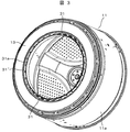
回転ドラム11は、図2,図3に示すように、ドラム槽11a,流体バランスリング13を有する。ドラム槽11aはステンレス鋼鈑で、流体バランスリング13は合成樹脂で形成されている。ドラム槽11aは、胴体部と奥側壁部と前側の開口部を有する。回転ドラム11が縦置きのときには、奥側壁部が底部になり、前側の開口部が上側の開口部になる。回転ドラム11は奥側壁部の外側面に設けたフランジ17を介して駆動モータに支持される。すなわち、回転ドラム11は回転軸心線方向の一端側(奥側壁部およびフランジ17)を駆動モータが含まれる回転ドラム駆動系で支持し、前記一端側の反対側である他端側に流体バランスリング13を配置している。これは、所謂、片持ち支持の回転支持機構であって、支持側の反対側であるドラム槽11aの開口部に流体バランスリング13を備えて回転アンバランスを抑えるようにしている。
As shown in FIGS. 2 and 3, the
この流体バランスリング13は脱水運転時の洗濯物9によるアンバランサの振動を低減する。流体バランスリング13は、図4,図5に示すように、流体収納部30と、カウンターウエイト33が収納される収納凹部31を有する。カウンターウエイト33は回転ドラム11の回転バランスを調整するものである。詳しくは後述する。流体収納部30は複数の流体収納室30a,30b,30c,30d,30eを有する。この環状の流体収納室30a,30b,30c,30d,30eは径方向に並び、かつドラム槽11aの回転軸心に対して同心的な配置になっている。
The
流体収納室30a,30b,30c,30d,30eは流体が円周方向に抵抗無く自由に流れにくいように半径方向にリブ(図示せず)が付けられている。流体収納室の中に充填される流体用の液体は比重が重く腐敗しない材料として塩化ナトリウム、塩化カリウムや塩化カルシュウムなどを水溶液が使用される。
The
流体バランスリング支持板40はステンレス鋼鈑で形成され、外周端がドラム槽11aの開口端にはぜ折かしめで締結されている。この流体バランスリングは流体バランスリング支持板40は支持されるので、流体バランスリングを直にドラム槽11aに取り付けとは違い、流体バランスリングは強い振動にも耐えるように確り支持される。外槽カバー32は流体バランスリング13を外側から覆うように設けられる。外槽カバー32は外周側が外槽2の前側(開口端側)に取り付け支持される。
The fluid balance
流体バランスリング13には、カウンターウエイト33を挿入する収納凹部31は設けられる。カウンターウエイト33は回転ドラム11の回転バランスの不釣合いで重さの軽い方に付ける。これにより、回転バランスの不釣合いが調整され、回転アンバランスない回転ドラム11を提供できる。また、カウンターウエイト33は回転バランスの不釣合いに応じた重さのものを適宜に用いることで、回転バランスの不釣合い調整はより適正に行われる。こうして回転ドラム自体に存在する回転アンバランスをカウンターウエイトで調整することにより、回転ドラムを高速脱水回転(1700RPM程度)で脱水運転においても振動の少ない洗濯乾燥機を提供できる。
The
回転ドラム11の回転アンバランスはアンバランス測定機で測定する。この測定で回転ドラム11の回転バランスの不釣合い重量、および不釣合いで重さの軽い方の位置を知ることができる。不釣合い重量に応じた重さのカウンターウエイト33を選び、重さの軽い方の位置にある収納凹部31にセットすることで、回転ドラム11の回転バランスは調整される。重さの軽い方の位置が複数存在するときは、不釣合い重量に応じた重さのカウンターウエイト33を選び、各々の位置にセットすることで調整を図る。
The rotational unbalance of the
また、回転バランスの調整後に再度測定し、回転バランスの調整が不十分なときはカウンターウエイト33を取り付けて再調整をする。この回転バランスの調整は回転ドラム自体で行っているが、回転ドラムと駆動モータが一体となった回転体の回転アンバランスを測定して回転バランスの調整を図ることも可能である。ただし、回転ドラムと駆動モータを連結した洗濯機構本体として組立った状態では、回転アンバランスの測定,カウンターウエイトの取り付け等で克服しなければならない課題がある。
Further, the measurement is performed again after adjusting the rotation balance. When the adjustment of the rotation balance is insufficient, the
収納凹部31はカウンターウエイト33を挿入する挿入口が流体バランスリング13を外側から覆うように設けられた外槽カバー32と向き合うように設けられている。このため、収納凹部の挿入口をドラム槽11aの内側向きに設けるのとは違い、ドラム槽11aで動き回る洗濯物が収納凹部31やカウンターウエイト33に接触して傷むこともない。また、収納凹部を流体バランスリング13の外周側に設けるのとは違い、収納凹部31やカウンターウエイト33と外槽2との間隙を十分に確保できる。
The
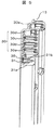
収納凹部31は、図6,図7に示すように、収納用内周壁31aと収納用外周壁31bと仕切り壁31cで形成される。径小の収納用内周壁31aと径大の収納用外周壁31bは流体収納室と同様にドラム槽11aの回転軸心に対して同心的な配置になっている。仕切り壁31cは径小の収納用内周壁31aと径大の収納用外周壁31bとの間に放射状に等間隔で設けられる。このため、仕切り壁31cで仕切られる複数(32個)の収納凹部31は回転ドラムの回転軸心を中心とする円周上に等間隔で配置される。
As shown in FIGS. 6 and 7, the
等間隔に配置された多数の収納凹部31を設けたので、カウンターウエイト33を取り付ける適性な位置を選ぶことができる。また、収納凹部31は収納用内周壁31aと収納用外周壁31bと仕切り壁31cで囲まれた凹部になっているので、挿入されたカウンターウエイト33の位置が保たれる。カウンターウエイト33の位置ずれが生じなく、調整後に回転バランスの狂いが起きない。
Since a large number of storage recesses 31 arranged at equal intervals are provided, an appropriate position for attaching the
収納凹部31には、図7に示すように、奥側(底側)から外側に向かって隆起するボス部34が設けられている。収納凹部31に挿入したカウンターウエイト33は、ボス部34に受け止められる。カウンターウエイト33の中央を貫通するネジ通し穴35(図8,図6に示す)に差し込んだネジ36(止め具)をボス部34のネジ穴に螺合することにより、カウンターウエイト33は収納凹部31に固定される。
As shown in FIG. 7, the
ボス部34は、図7に示すように、外周に4つの補強リブ34a,34bを有する。補強リブ34aは長方形状をした収納凹部31の長手方向に形成されている。補強リブ34bは長方形状をした収納凹部31の短手方向に形成されている。補強リブ34bは収納凹部31の内壁面につながっているが、補強リブ34aの方は収納凹部31の内壁面に達していない。このため、収納凹部31に収めたカウンターウエイト33はカウンターウエイト33の長手方向端部(一方)を押すことで、他方の長手方向端部が浮き上がるように収納凹部31から突き出る。カウンターウエイト33の入れ替えが容易であるので、回転バランスの調整作業が容易に行われる。なお、カウンターウエイト33の長さは収納凹部31の長さよりも幾分短めにすると、入れ替えがしやすい。
As shown in FIG. 7, the
図6,図7の図示から分かるように、収納凹部31の挿入口は挿入口縁部が収納用内周壁31aの前側端面や流体収納部30の前側端面よりも後退するように下がっている。仕切り壁31cの前側端面や収納用外周壁31bの前側端面は挿入口縁部と面一になっている。そして、カウンターウエイト33を止めるネジ36の頭が収納凹部31の挿入口縁部から外側に突出しない範囲でカウンターウエイト33の厚みを選んでいる。これは、洗濯物が仕切り壁31cの前側端面、ネジ36ないしカウンターウエイト33に接触するのを回避するためである。
As can be seen from FIGS. 6 and 7, the insertion port of the
すなわち、収納凹部31を形成する収納用内周壁31aの前側端面と外槽カバー32の内周側端部32aは隙間(3mm程度)を介して対向している。収納用内周壁31aの前側端面と内周側端部32aは環状である。そして、回転側の収納用内周壁31aが回転ドラム11の投入口11bになり、回転しない側の内周側端部32aが外槽2の投入口11dになっている。つまり、仕切り壁31cの前側端面、カウンターウエイト33ないし止めるネジ36の頭が収納用内周壁31aの前側端面よりも後退した位置になっているので、回転ドラム11で動き回る洗濯物の端が前記隙間(3mm程度)から進入しても、仕切り壁31cの前側端面、カウンターウエイト33ないし止めるネジ36の頭に洗濯物が接触するのは回避される。
That is, the front end surface of the storage inner
カウンターウエイト33は、図8に示すように、鋼鈑のカウンターウエイト片板37を積み重ねて構成する。長方形状したカウンターウエイト片板37は中央のネジ通し穴35を中心として両側の対象位置に結合用の凹凸部35aを有する。この凹凸部35aは押出用の治具でカウンターウエイト片板37を厚み方向にプレスして形成する。カウンターウエイト片板37は押された面が凹み、反対側面が突出(凸)して凹凸部35aができる。
As shown in FIG. 8, the
積み重ねるカウンターウエイト片板37は隣合う凹凸が嵌合する。この嵌合により複数のカウンターウエイト片板37が結合してカウンターウエイト33ができる。端用のカウンターウエイト片板38は中央のネジ通し穴35を中心として両側の対象位置に結合用の溝穴38aを有する。この溝穴38aに凹凸部35aの凸が嵌合する。この嵌合によりカウンターウエイト片板37と端用のカウンターウエイト片板38が結合してカウンターウエイト33ができる。
Adjacent irregularities fit into the
複数のカウンターウエイト片板37,端用のカウンターウエイト片板38で作られるカウンターウエイト33は凹凸部35a、および溝穴38aによって結合されるので、ばらばらに崩れることがなく、収納凹部31への挿入や取り出しがし易く、回転バランスの調整作業がし易い。また、カウンターウエイト33は端用のカウンターウエイト片板38を内側にして収納凹部31に挿入する。端用のカウンターウエイト片板38は凸がないので、ボス部34(補強リブを含む)に対する座りが安定する。それとともに収納凹部31に挿入されたカウンターウエイト33の外側に置かれるカウンターウエイト片板38は表面
が凹凸部35aの凹になるので、凸が表面に来る場合に比べ、洗濯物等と接触する可能性が少なくなる。また、カウンターウエイト33はカウンターウエイト片板37の重ね枚数を変えて重さを加減できる。このため、回転ドラム11の回転バランスの調整を容易に行うことができる。
The
回転ドラム11は、前述したように、回転軸心線方向の一端側(奥側壁部およびフランジ17)を駆動モータが含まれる回転ドラム駆動系で支持した片持ち支持の回転支持機構となっている。そして、回転ドラム駆動系に含まれる主軸18で支持する支持部の反対側である回転ドラム11の前側に流体バランスリング13を設けることにより、回転ドラム11に偏在する洗濯物で発生する回転アンバランスの振動を緩和している。この回転アンバランスの振動は支持部を支点として流体バランスリング13がある回転ドラム11の前側が大きく振幅する首振り振動を呈する。カウンターウエイト33は首振り振動の振幅が大きくなる回転ドラム11の前側に置かれる流体バランスリング13に設けるので、回転アンバランスによる振動の抑制が大きく作用する。このため、小さな少量のカウンターウエイトより回転ドラムの回転バランスを調整することができる。
As described above, the
また、回転アンバランスの調整はカウンターウエイトが取り付けられる収納凹部を流体バランスリングの内周側部位に設ける構成にしたので安価である。すなわち、流体バランスリングにある流体収納部の内周側に収納凹部を追加する構成であるので、流体バランスリングの内周の寸法形状を変更するだけである。外周側の寸法形状は変更がないので、ドラム槽や外槽の寸法を変える必要はなく、安価になるのである。 Further, the adjustment of the rotational imbalance is inexpensive because the storage recess to which the counterweight is attached is provided in the inner peripheral portion of the fluid balance ring. That is, since the storage concave portion is added to the inner peripheral side of the fluid storage portion in the fluid balance ring, only the dimensional shape of the inner periphery of the fluid balance ring is changed. Since there is no change in the dimensional shape on the outer peripheral side, there is no need to change the dimensions of the drum tank and the outer tank, and the cost is reduced.
1 外枠筐体
2 外槽
3 サスペンション
4 引きバネ
11 回転ドラム
13 流体バランスリング
30 流体収納部
31 収納凹部
31a 径小の収納用内周壁
31b 径大の収納用外周壁
31c 仕切り壁
32 外槽カバー
33 カウンターウエイト
34 ボス部
35 ネジ通し穴
36 ネジ
37 カウンターウエイト片板
40 流体バランスリング支持板
DESCRIPTION OF
Claims (6)
洗濯水を溜め、かつ前記回転ドラムを内置する外槽と、
前記回転ドラムを駆動する駆動モータが含まれる回転ドラム駆動系と、
前記外槽を内置する外枠と、
前記外枠に前記外槽を防振支持する防振機構を備え、
前記回転ドラムは、前記洗濯物が入れられるドラム槽と、回転ドラムの回転バランスをとる流体バランスリングを有し、
かつ前記回転ドラムは、回転軸心線方向の一端側を前記回転ドラム駆動系で支持した片持ち支持の回転支持機構であって、前記一端側の反対側である他端側に前記流体バランスリングを配置している、
洗濯機において、
前記回転ドラムの回転バランスを調整するカウンターウエイトを流体バランスリングに備えることを特徴とする洗濯機。 A rotating drum for washing laundry,
An outer tub for storing washing water and placing the rotating drum therein;
A rotating drum driving system including a driving motor for driving the rotating drum;
An outer frame for placing the outer tub,
Provided with an anti-vibration mechanism for anti-vibration support of the outer tub on the outer frame,
The rotating drum has a drum tub in which the laundry is put, and a fluid balance ring that balances the rotation of the rotating drum,
And the rotary drum, one end of the rotation axis line direction to a rotation support mechanism of the cantilevered was supported by the rotary drum driving system, the fluid balance on the other side which is opposite to the one end Arranging the ring,
In the washing machine,
A washing machine comprising a fluid balance ring provided with a counterweight for adjusting the rotational balance of the rotary drum.
前記回転バランスの不釣り合いで重さの軽い方に設ける前記カウンターウエイトの重さは不釣り合い重量に応じた重さであることを特徴とする洗濯機。 The washing machine according to claim 1,
The washing machine according to claim 1, wherein a weight of the counterweight provided in a lighter weight with an unbalanced rotational balance is a weight corresponding to the unbalanced weight.
前記カウンターウエイトは鋼鈑のカウンターウエイト片板を重ねて構成することを特徴とする洗濯機。 The washing machine according to claim 1,
2. The washing machine according to claim 1, wherein the counterweight is configured by stacking steel counterweight pieces.
前記カウンターウエイト片板は重ね合わせ方向に形成された結合用の凹凸部を有することを特徴とする洗濯機。 The washing machine according to claim 3,
2. The washing machine according to claim 1, wherein the counterweight piece plate has a concavity and convexity portion for bonding formed in an overlapping direction.
前記流体バランスリングは前記回転ドラムの回転軸心線を中心とする円周上に等間隔で形成した複数の収納凹部を有し、前記外槽は前記流体バランスリングを外側から覆う外槽カバーを有し、前記収納凹部は前記カウンターウエイトを挿入する挿入口が前記外槽カバーに向いていることを特徴とする洗濯機。 The washing machine according to claim 1,
The fluid balance ring has a plurality of storage recesses formed at equal intervals on a circumference centered on the rotation axis of the rotary drum, and the outer tank is provided with an outer tank cover that covers the fluid balance ring from the outside. The washing recess is characterized in that the insertion recess into which the counterweight is inserted faces the outer tub cover.
前記流体バランスリングは前記回転ドラムの回転軸心線を中心とする円周上に等間隔で形成した複数の収納凹部を有し、この収納凹部に挿入する前記カウンターウエイトの止め具を備え、前記止め具の頭部、および前記カウンターウエイトは、前記収納凹部の挿入口の口縁部よりも内側に位置することを特徴とする洗濯機。 The washing machine according to claim 1,
The fluid balance ring has a plurality of storage recesses formed at equal intervals on a circumference centering on the rotation axis of the rotary drum, and includes a counterweight stopper inserted into the storage recess, The washing machine according to claim 1, wherein the head of the stopper and the counterweight are located on the inner side of the mouth edge of the insertion opening of the storage recess.
Priority Applications (2)
| Application Number | Priority Date | Filing Date | Title |
|---|---|---|---|
| JP2009197567A JP5124544B2 (en) | 2009-08-28 | 2009-08-28 | Washing machine |
| CN2010102593215A CN102002840A (en) | 2009-08-28 | 2010-08-19 | Washing machine |
Applications Claiming Priority (1)
| Application Number | Priority Date | Filing Date | Title |
|---|---|---|---|
| JP2009197567A JP5124544B2 (en) | 2009-08-28 | 2009-08-28 | Washing machine |
Related Child Applications (1)
| Application Number | Title | Priority Date | Filing Date |
|---|---|---|---|
| JP2012236223A Division JP5422722B2 (en) | 2012-10-26 | 2012-10-26 | Washing machine |
Publications (2)
| Publication Number | Publication Date |
|---|---|
| JP2011045600A JP2011045600A (en) | 2011-03-10 |
| JP5124544B2 true JP5124544B2 (en) | 2013-01-23 |
Family
ID=43810530
Family Applications (1)
| Application Number | Title | Priority Date | Filing Date |
|---|---|---|---|
| JP2009197567A Active JP5124544B2 (en) | 2009-08-28 | 2009-08-28 | Washing machine |
Country Status (2)
| Country | Link |
|---|---|
| JP (1) | JP5124544B2 (en) |
| CN (1) | CN102002840A (en) |
Cited By (1)
| Publication number | Priority date | Publication date | Assignee | Title |
|---|---|---|---|---|
| CN105040349A (en) * | 2014-04-23 | 2015-11-11 | 日立空调·家用电器株式会社 | Tumbling-box washing machine |
Families Citing this family (1)
| Publication number | Priority date | Publication date | Assignee | Title |
|---|---|---|---|---|
| JP2020103565A (en) * | 2018-12-27 | 2020-07-09 | 青島海爾洗衣机有限公司QingDao Haier Washing Machine Co.,Ltd. | Drum type washing machine |
Family Cites Families (9)
| Publication number | Priority date | Publication date | Assignee | Title |
|---|---|---|---|---|
| JP2954031B2 (en) * | 1995-08-28 | 1999-09-27 | 三星電子株式会社 | Washing machine balance |
| DE69608876T3 (en) * | 1995-12-28 | 2006-05-24 | Samsung Electronics Co., Ltd., Suwon | Drum machine with balancing devices |
| CA2206923C (en) * | 1996-06-28 | 2001-07-10 | Hans Oetiker Ag Maschinen- Und Apparatefabrik | Improved balancing arrangement for hollow drive shafts |
| CN2347990Y (en) * | 1998-09-30 | 1999-11-10 | 中国济南洗衣机厂 | Drum washing machine with balancing means |
| JP2003093787A (en) * | 2001-09-27 | 2003-04-02 | Sanyo Electric Co Ltd | Drum type washing machine |
| JP2003230792A (en) * | 2002-02-07 | 2003-08-19 | Toshiba Corp | Drum type washing machine |
| JP4334499B2 (en) * | 2005-04-21 | 2009-09-30 | 株式会社東芝 | Drum washing machine |
| KR20070119322A (en) * | 2006-06-15 | 2007-12-20 | 엘지전자 주식회사 | Washing machine |
| JP4393501B2 (en) * | 2006-11-08 | 2010-01-06 | 日立アプライアンス株式会社 | Drum washing machine |
-
2009
- 2009-08-28 JP JP2009197567A patent/JP5124544B2/en active Active
-
2010
- 2010-08-19 CN CN2010102593215A patent/CN102002840A/en active Pending
Cited By (1)
| Publication number | Priority date | Publication date | Assignee | Title |
|---|---|---|---|---|
| CN105040349A (en) * | 2014-04-23 | 2015-11-11 | 日立空调·家用电器株式会社 | Tumbling-box washing machine |
Also Published As
| Publication number | Publication date |
|---|---|
| CN102002840A (en) | 2011-04-06 |
| JP2011045600A (en) | 2011-03-10 |
Similar Documents
| Publication | Publication Date | Title |
|---|---|---|
| KR101644885B1 (en) | washing machine | |
| KR20130016932A (en) | Washing machine | |
| KR101605760B1 (en) | Washing machine | |
| KR20130080222A (en) | Washing machine | |
| KR20140018681A (en) | Washing machine | |
| JP5422722B2 (en) | Washing machine | |
| JP2012130475A (en) | Drum washing machine | |
| RU2536025C2 (en) | Washing machine manufacture method | |
| EP2390400B1 (en) | Laundry machine | |
| RU2505634C2 (en) | Machine for laundry processing | |
| JP5124544B2 (en) | Washing machine | |
| JP2012130474A (en) | Drum washing machine | |
| CN107429465B (en) | Washing machine | |
| EP2435613B1 (en) | Laundry machine | |
| JP2011072350A (en) | Washing machine | |
| KR100826206B1 (en) | drum type washer | |
| JP2015096233A (en) | Washing machine | |
| JP4393501B2 (en) | Drum washing machine | |
| JP5400523B2 (en) | Liquid balancer and washing machine equipped with the same | |
| KR101186600B1 (en) | gasket for drum washing machine | |
| EP2435610B1 (en) | Laundry machine | |
| KR101792506B1 (en) | Laundry Machine | |
| JP5256238B2 (en) | Drum washing machine | |
| JP2017074188A (en) | Drum type washing machine | |
| KR101692728B1 (en) | Control method for washing machine |
Legal Events
| Date | Code | Title | Description |
|---|---|---|---|
| A621 | Written request for application examination |
Free format text: JAPANESE INTERMEDIATE CODE: A621 Effective date: 20110805 |
|
| A521 | Written amendment |
Free format text: JAPANESE INTERMEDIATE CODE: A523 Effective date: 20110805 |
|
| A977 | Report on retrieval |
Free format text: JAPANESE INTERMEDIATE CODE: A971007 Effective date: 20120112 |
|
| A131 | Notification of reasons for refusal |
Free format text: JAPANESE INTERMEDIATE CODE: A131 Effective date: 20120124 |
|
| A521 | Written amendment |
Free format text: JAPANESE INTERMEDIATE CODE: A523 Effective date: 20120326 |
|
| TRDD | Decision of grant or rejection written | ||
| A01 | Written decision to grant a patent or to grant a registration (utility model) |
Free format text: JAPANESE INTERMEDIATE CODE: A01 Effective date: 20121002 |
|
| A01 | Written decision to grant a patent or to grant a registration (utility model) |
Free format text: JAPANESE INTERMEDIATE CODE: A01 |
|
| A61 | First payment of annual fees (during grant procedure) |
Free format text: JAPANESE INTERMEDIATE CODE: A61 Effective date: 20121029 |
|
| FPAY | Renewal fee payment (event date is renewal date of database) |
Free format text: PAYMENT UNTIL: 20151102 Year of fee payment: 3 |
|
| R150 | Certificate of patent or registration of utility model |
Ref document number: 5124544 Country of ref document: JP Free format text: JAPANESE INTERMEDIATE CODE: R150 Free format text: JAPANESE INTERMEDIATE CODE: R150 |
|
| S531 | Written request for registration of change of domicile |
Free format text: JAPANESE INTERMEDIATE CODE: R313531 |
|
| S533 | Written request for registration of change of name |
Free format text: JAPANESE INTERMEDIATE CODE: R313533 |
|
| R350 | Written notification of registration of transfer |
Free format text: JAPANESE INTERMEDIATE CODE: R350 |