JP5122312B2 - Seal connector for shielded cable connection - Google Patents
Seal connector for shielded cable connection Download PDFInfo
- Publication number
- JP5122312B2 JP5122312B2 JP2008023924A JP2008023924A JP5122312B2 JP 5122312 B2 JP5122312 B2 JP 5122312B2 JP 2008023924 A JP2008023924 A JP 2008023924A JP 2008023924 A JP2008023924 A JP 2008023924A JP 5122312 B2 JP5122312 B2 JP 5122312B2
- Authority
- JP
- Japan
- Prior art keywords
- shielded cable
- nipple
- nut
- elastic sleeve
- covering
- Prior art date
- Legal status (The legal status is an assumption and is not a legal conclusion. Google has not performed a legal analysis and makes no representation as to the accuracy of the status listed.)
- Expired - Fee Related
Links
Images


Description
本発明は、機器との接続に用いるシールドケーブルについて、シール(漏洩防止)のために使用するシールドケーブル接続用のシールコネクタに関する。 The present invention relates to a shielded connector for connecting a shielded cable used for sealing (leakage prevention) of a shielded cable used for connection with a device.
従来、機器との接続に用いるケーブルについて、ニップル内に挿入したシール部材に対して当該ニップルとフクロナットとで締め付けを行うことにより、シール部材を軸中心(内径方向)に縮小させてケーブルに密着して漏洩防止を図った技術の一例が開示されている(例えば特許文献1を参照)。
特許文献1の技術では一般的なケーブルに適用したが、この技術をシールドケーブルにも同様に適用することが可能である。適用例を図示すると、例えば図6のようになる。当該図6の場合はワイヤーブレード113にアース線111が接続されているので、シールドケーブル110をコネクタ100で機器70の所定穴に固定し、アース線111を機器70に備え付けの端子等に締結してアースを取る必要がある。したがって、コネクタ100の固定作業以外にアース線111の締結作業が必要となる点で手間と時間を要し、アース線111の締結を忘れた場合にはアースされないという問題点があった。
Although the technique of Patent Document 1 is applied to a general cable, this technique can be similarly applied to a shielded cable. An application example is shown in FIG. 6, for example. In the case of FIG. 6, since the ground wire 111 is connected to the wire blade 113, the shield cable 110 is fixed to a predetermined hole of the
本発明はこのような点に鑑みてなしたものであり、漏洩防止を図りながらも、従来よりも作業量を減らしてワイヤーブレードを確実にアースできるシールドケーブル接続用のシールコネクタを提供することを目的とする。 The present invention has been made in view of the above points, and provides a sealed connector for connecting a shielded cable that can reliably ground the wire blade by reducing the amount of work compared to the prior art while preventing leakage. Objective.
(1)課題を解決するための手段(以下では単に「解決手段」と呼ぶ。)1は、請求項1に記載した通りである。
解決手段1によれば、ワイヤーブレードを被覆部に被せた状態で弾性スリーブをニップル内に挿入し、ニップルの外端とテーパワッシャの外端との間に二つのフランジ部を位置させる。この状態でニップルとフクロナットとを噛合してゆくと二つのフランジ部がともに溝部側に圧縮され、当該溝部を中心として軸心方向に膨出してシールドケーブルの外周に食い込むようになる。ワイヤーブレードは直接接触する導電性のニップルおよびロックナットを通じて機器(例えば筐体)にアースされるので、従来のようなアース線の締結作業は不要になり、従来よりも作業量を減らすことができる。また、ニップルとフクロナットとを噛合するだけで弾性スリーブがシールドケーブルに食い込んで密着するので、漏洩防止を図ることができる。
(1) Means for solving the problem (hereinafter simply referred to as “solution means”) 1 is as described in claim 1.
According to the solution 1, the elastic sleeve is inserted into the nipple while the wire blade is covered with the covering portion, and the two flange portions are positioned between the outer end of the nipple and the outer end of the taper washer. In this state, when the nipple and the hook nut are engaged with each other, the two flange portions are both compressed toward the groove portion, bulge in the axial direction around the groove portion, and bite into the outer periphery of the shield cable. Since the wire blade is grounded to the device (for example, the housing) through the conductive nipple and the lock nut that are in direct contact with each other, there is no need for fastening the ground wire as in the conventional case, and the work amount can be reduced as compared with the conventional case. . Further, since the elastic sleeve bites into and comes into close contact with the shielded cable simply by engaging the nipple and the owl nut, it is possible to prevent leakage.
(2)解決手段2は、請求項2に記載した通りである。
解決手段2によれば、ニップルのテーパ部はシールドケーブルを挿入する方向に次第に狭くなるように形成されている。シールドケーブルの直径が小さかったり大きくても、ワイヤーブレードを被覆部に被せた状態で弾性スリーブをニップル内に挿入するだけで確実にニップルを通じて機器にアースすることが可能になる。
(2) Solution 2 is as described in claim 2.
According to the solution 2, the tapered portion of the nipple is formed so as to become gradually narrower in the direction in which the shield cable is inserted. Even if the diameter of the shielded cable is small or large, it is possible to reliably ground the device through the nipple by simply inserting the elastic sleeve into the nipple with the wire blade placed on the covering portion.
(3)解決手段3は、請求項3に記載した通りである。
解決手段3によれば、弾性スリーブは、被覆部が形成された側の端部を、シールドケーブルにおける外装被覆の端部に引っ掛けられる形状(例えばL字状等)に形成している。そのため、弾性スリーブに備えられた二つのフランジ部をニップルの外端とテーパワッシャの外端との間に確実に位置させることができる。よって、弾性スリーブの溝部を中心としてシールドケーブルの外周に食い込ませて漏洩防止を図ることができる。
(3) The solving means 3 is as described in claim 3.
According to the solution 3, the elastic sleeve is formed such that the end portion on the side where the covering portion is formed is shaped to be hooked on the end portion of the outer sheath of the shielded cable (for example, an L shape). Therefore, the two flange portions provided in the elastic sleeve can be reliably positioned between the outer end of the nipple and the outer end of the taper washer. Therefore, it is possible to prevent leakage by biting into the outer periphery of the shielded cable with the groove portion of the elastic sleeve as the center.
本発明によれば、漏洩防止を図りながらも、従来よりも作業量を減らしてワイヤーブレードを確実にアースすることができる。 According to the present invention, it is possible to reliably ground the wire blade by reducing the amount of work compared to the conventional one while preventing leakage.
本発明を実施するための最良の形態について、図1〜図5を参照しながら説明する。 The best mode for carrying out the present invention will be described with reference to FIGS.
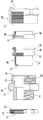
まず図1には、シールコネクタの分解構成例を模式的に一部破断図で表す。すなわち上半分を断面図で表し、下半分を外観図で表す。本発明のシールコネクタは、ロックナット10,ニップル20,弾性スリーブ30,テーパワッシャ40,フクロナット50などの部品によって構成される。弾性スリーブ30を除いて、各部品は導電性の素材(例えば金属や導電性樹脂等)で形成する。
First, FIG. 1 schematically shows an exploded configuration example of a seal connector in a partially broken view. That is, the upper half is represented by a sectional view and the lower half is represented by an external view. The seal connector of the present invention is constituted by components such as a
ロックナット10はネジ部11と先鋭部12等を有する。ネジ部11は後述するニップル20のネジ部24と噛合し、シールコネクタ全体を機器に固定する。先鋭部12は先端が尖っており、機器に固定した際に筐体と接触して導通(アース)を確実にする。
The
ニップル20は、収納部21,テーパ部22,傾斜部23およびネジ部24,25等を有する。収納部21は後述するパッキン71(図3を参照)を収納する。テーパ部22は、シールドケーブルを挿入する方向(すなわち図面左方向)に次第に狭く(言い換えれば直径が小さく)なるように形成する。傾斜部23は後述するテーパワッシャ40の傾斜部41とともに弾性スリーブ30のフランジ部33,35を溝部34側に圧縮する。ネジ部25はフクロナット50のネジ部51と噛合し、上述した傾斜部23,41によるフランジ部33,35の圧縮を行う。
The
弾性スリーブ30は弾性素材で形成され、鉤部31,被覆部32,溝部34および二つのフランジ部33,35等を有する。鉤部31は被覆部32が形成された側の端部であって、本例では軸心方向に突出するようにL字状に形成している。被覆部32はシールドケーブルのワイヤーブレードを被せる外周面の部位である。二つのフランジ部33,35は、その相互間に溝部34が形成される。
The
テーパワッシャ40は傾斜部41とフランジ部42等を有する。フクロナット50はネジ部51と係止部52等を有する。テーパワッシャ40はフランジ部42が係止部52で係止するようにフクロナット50の中に入れて用いる。
The
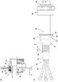
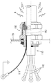
上述のように構成されるシールコネクタを用いてシールドケーブルを機器に固定する方法について、図2〜図4を参照して説明する。図2にはシールドケーブルに弾性スリーブ等を通した状態を表す。図3にはシールコネクタを締結する前の状態を表す。図4にはシールコネクタを締結した後の状態を表す。図5には図4の一部を拡大して表す。 A method of fixing the shielded cable to the device using the seal connector configured as described above will be described with reference to FIGS. FIG. 2 shows a state where an elastic sleeve or the like is passed through the shielded cable. FIG. 3 shows a state before the seal connector is fastened. FIG. 4 shows a state after the seal connector is fastened. FIG. 5 shows an enlarged part of FIG.
まず、収納部21にパッキン71を嵌め込んだニップル20を、ロックナット10を用いて機器70の所定穴に固定する。具体的には、ロックナット10の先鋭部12が機器70に当たって止まるまで、ロックナット10のネジ部11とニップル20のネジ部24とを噛合して締結する。こうして固定した状態を図2(A)に示す。なお、機器70(具体的には筐体)は予めアースされているものとする。
First, the
一方、弾性スリーブ30,テーパワッシャ40およびフクロナット50をシールドケーブル60に通す。このうち弾性スリーブ30は、鉤部31が外装被覆64の端部に当たって止まっている。このときの状態を図2(B)に示す。本例のシールドケーブル60は、内側から外側に向かって複数本(図2(B)では3本であるが、実際には数十本)の電線61,内装被覆62,ワイヤーブレード63,外装被覆64の順で構成している。
On the other hand, the
図2(B)に表す状態でワイヤーブレード63の端部を裏返すようにして(矢印D1を参照)、ワイヤーブレード63が弾性スリーブ30の被覆部32を覆う。そしてシールドケーブル60の電線61からニップル20を通し、ニップル20のネジ部25とフクロナット50のネジ部51とを少しだけ噛合すると図3のようになる。
In the state shown in FIG. 2B, the end of the
図3において、裏返して被覆部32を覆ったワイヤーブレード63はニップル20のテーパ部22と密着状態になる。また、ニップル20の傾斜部23(外端)とテーパワッシャ40の傾斜部41(外端)との間に二つのフランジ部33,35が位置する。
噛合しているニップル20のネジ部25とフクロナット50のネジ部51とを締め付けてゆくと、フクロナット50が所定方向(図面の矢印D2方向)に移動する。この移動に従って、ニップル20の傾斜部23とテーパワッシャ40の傾斜部41とが弾性スリーブ30のフランジ部33,35をともに溝部34側に圧縮し、溝部34が次第に無くなってゆく。フクロナット50をニップル20に締結し終えると、図4に表すようにフランジ部33,35が接触した状態となり、かつ溝部34を中心とする部位の弾性スリーブ30がシールドケーブル60の軸心方向に膨出して外周に食い込む。
In FIG. 3, the
When the threaded
図4の一部を拡大した図5を参照すると、被覆部32を覆ったワイヤーブレード63はテーパ部22すなわちニップル20に接触し、ニップル20に噛合するロックナット10の先鋭部12が機器70に接触する。したがって、外来ノイズNはワイヤーブレード63→ニップル20→ロックナット10→機器70の順に流れてアースされる(図5に表す矢印D3を参照)。
Referring to FIG. 5 in which a part of FIG. 4 is enlarged, the
上述した実施の形態によれば、以下に表す各効果を得ることができる。
(1)ワイヤーブレード63を被覆部32に被せた状態で弾性スリーブ30をニップル20内に挿入し、ニップル20の傾斜部23とテーパワッシャ40の傾斜部41との間に二つのフランジ部33,35を位置させた(図3を参照)。この状態でニップル20とフクロナット50とを噛合してゆくと二つのフランジ部33,35がともに溝部34側に圧縮され、当該溝部34を中心として軸心方向に膨出してシールドケーブル60の外周に食い込む(図4を参照)。ワイヤーブレード63は直接接触するニップル20およびロックナット10を通じて機器70にアースされるので(図5を参照)、従来のようなアース線111の締結作業は不要になり、従来よりも作業量を減らすことができる。また、ニップル20とフクロナット50とを噛合するだけで弾性スリーブ30がシールドケーブル60に食い込んで密着するので、漏洩防止を図ることができる。
According to the embodiment described above, the following effects can be obtained.
(1) The
(2)ニップル20のテーパ部22はシールドケーブル60を挿入する方向に次第に狭くなるように形成した(図1,図3を参照)。シールドケーブル60の直径が小さかったり大きくても、ワイヤーブレード63を被覆部32に被せた状態で弾性スリーブ30をニップル20内に挿入するだけで確実にニップル20を通じて機器70にアースできる。
(2) The tapered
(3)弾性スリーブ30の鉤部31は、シールドケーブル60における外装被覆64の端部に引っ掛けられるL字状に形成した(図1,図3を参照)。そのため、弾性スリーブ30に備えられた二つのフランジ部33,35をニップル20の傾斜部23とテーパワッシャ40の傾斜部41との間に確実に位置させることができる。よって、弾性スリーブ30の溝部34を中心としてシールドケーブル60の外周に食い込ませて漏洩防止を図ることができる。
(3) The
〔他の実施の形態〕
以上では本発明を実施するための最良の形態について説明したが、本発明は当該形態に何ら限定されるものではない。言い換えれば、本発明の要旨を逸脱しない範囲内において、種々なる形態で実施することもできる。例えば、次に示す各形態を実現してもよい。
[Other Embodiments]
Although the best mode for carrying out the present invention has been described above, the present invention is not limited to this mode. In other words, various forms can be implemented without departing from the scope of the present invention. For example, the following forms may be realized.
(1)上述した実施の形態では、ロックナット10を用いてニップル20を機器70に固定するにあたって、ロックナット10のネジ部11とニップル20のネジ部24とを噛合して締結した(図2(B)を参照)。この形態に代えて、ネジ部以外の締結手段によりロックナット10を用いてニップル20を機器70に固定してもよく、ロックナット10を用いずにニップル20のみを導電性の締結部材(例えばネジやリベット等)で機器70に固定してもよい。いずれの形態にせよ、ニップル20からロックナット10または締結部材を通じて機器70にアースすることができる。
(1) In the above-described embodiment, when the
(2)上述した実施の形態では、弾性スリーブ30の鉤部31はシールドケーブル60における外装被覆64の端部に引っ掛けられるL字状に形成した(図1,図3を参照)。この形態に代えて、L字状以外の形状(例えばU字状やJ字状などの形状)であって外装被覆64の端部に引っ掛けられる形状で鉤部31を形成してもよい。L字状以外の形状であっても、弾性スリーブ30に備えられた二つのフランジ部33,35をニップル20の傾斜部23とテーパワッシャ40の傾斜部41との間に確実に位置させることができる。したがって、上述した実施の形態と同様の効果を得ることができる。
(2) In the above-described embodiment, the
(3)上述した実施の形態では、テーパワッシャ40とフクロナット50とを別体に構成した(図1を参照)。この形態に代えて、テーパワッシャ40とフクロナット50とを一体に構成してもよい。言い換えれば、フクロナット50における係止部52の部位に傾斜部41を備える構造とすればよい。この構造であっても、ニップル20の傾斜部23とともに二つのフランジ部33,35をともに溝部34側に圧縮させ、当該溝部34を中心として軸心方向に膨出してシールドケーブル60の外周に食い込ませることができる。したがって、上述した実施の形態と同様の効果を得ることができる。
(3) In the above-described embodiment, the tapered
10 ロックナット
11 ネジ部
12 先鋭部
20 ニップル
21 収納部
22 テーパ部
23 傾斜部
24 ネジ部
25 ネジ部
30 弾性スリーブ
31 鉤部
32 被覆部
33,35 フランジ部
34 溝部
40 テーパワッシャ
41 傾斜部
42 フランジ部
50 フクロナット
51 ネジ部
52 係止部
60 シールドケーブル
61 電線
62 内装被覆
63 ワイヤーブレード
64 外装被覆
70 機器
71 パッキン
100 コネクタ
110 シールドケーブル
111 アース線
112 電線
113 ワイヤーブレード
N ノイズ
DESCRIPTION OF
Claims (3)
シールドケーブルを挿入可能な筒状に形成され、挿入したシールドケーブルのワイヤーブレードを外周面に被せるための被覆部と、溝部を挟んで形成した二つのフランジ部とを備えた弾性スリーブを有し、
弾性スリーブは、ワイヤーブレードを被覆部に被せた状態でニップル内に挿入されるとともに、ニップルの外端とテーパワッシャの外端との間に二つのフランジ部を位置させ、ニップルとフクロナットとの噛合時に二つのフランジ部がともに溝部側に圧縮されて当該溝部を中心として軸心方向に膨出してシールドケーブルの外周に食い込み可能となるように構成したシールドケーブル接続用のシールコネクタ。 A shielded cable having a conductive nipple that can be inserted into a shielded cable and fixed to a predetermined hole of the device using a lock nut, a owl nut that meshes with the nipple, and a taper washer attached to the inside of the owl nut. A sealed connector for connecting a shielded cable that is tightened by engaging a nipple inserted with a crocodile nut,
It is formed in a cylindrical shape into which a shielded cable can be inserted, and has an elastic sleeve provided with a covering portion for covering the outer peripheral surface with the wire blade of the inserted shielded cable, and two flange portions formed with a groove interposed therebetween,
The elastic sleeve is inserted into the nipple with the wire blade covered, and two flanges are positioned between the outer end of the nipple and the outer end of the taper washer to engage the nipple and the crocodile nut. A shield connector for connecting a shielded cable, wherein two flanges are sometimes compressed toward the groove and bulge in the axial direction around the groove so as to be able to bite into the outer periphery of the shielded cable.
ニップルは、シールドケーブルを挿入する方向に次第に狭くなるように形成したテーパ部を有するシールドケーブル接続用のシールコネクタ。 A sealed connector for connecting a shielded cable according to claim 1,
The nipple is a sealed connector for connecting a shielded cable having a tapered portion formed so as to be gradually narrowed in a direction in which the shielded cable is inserted.
弾性スリーブは、被覆部が形成された側の端部を、シールドケーブルにおける外装被覆の端部に引っ掛けられる形状に形成したシールドケーブル接続用のシールコネクタ。 A sealed connector for connecting a shielded cable according to claim 1 or 2,
The elastic sleeve is a sealed connector for connecting a shielded cable in which the end portion on the side where the covering portion is formed is hooked to the end portion of the sheath covering of the shielded cable.
Priority Applications (1)
| Application Number | Priority Date | Filing Date | Title |
|---|---|---|---|
| JP2008023924A JP5122312B2 (en) | 2008-02-04 | 2008-02-04 | Seal connector for shielded cable connection |
Applications Claiming Priority (1)
| Application Number | Priority Date | Filing Date | Title |
|---|---|---|---|
| JP2008023924A JP5122312B2 (en) | 2008-02-04 | 2008-02-04 | Seal connector for shielded cable connection |
Publications (2)
| Publication Number | Publication Date |
|---|---|
| JP2009189098A JP2009189098A (en) | 2009-08-20 |
| JP5122312B2 true JP5122312B2 (en) | 2013-01-16 |
Family
ID=41071788
Family Applications (1)
| Application Number | Title | Priority Date | Filing Date |
|---|---|---|---|
| JP2008023924A Expired - Fee Related JP5122312B2 (en) | 2008-02-04 | 2008-02-04 | Seal connector for shielded cable connection |
Country Status (1)
| Country | Link |
|---|---|
| JP (1) | JP5122312B2 (en) |
Families Citing this family (2)
| Publication number | Priority date | Publication date | Assignee | Title |
|---|---|---|---|---|
| JP5093048B2 (en) * | 2008-10-24 | 2012-12-05 | 株式会社豊田自動織機 | Cable fixing structure |
| US9282654B2 (en) | 2014-05-06 | 2016-03-08 | Honeywell International Inc. | HVAC controller with air flow barrier |
Family Cites Families (6)
| Publication number | Priority date | Publication date | Assignee | Title |
|---|---|---|---|---|
| JPS5615890Y2 (en) * | 1977-02-10 | 1981-04-14 | ||
| JP2514093Y2 (en) * | 1990-06-22 | 1996-10-16 | 株式会社北澤電機製作所 | Wire penetration hardware for electromagnetic interference |
| GB2269711B (en) * | 1992-08-11 | 1996-04-03 | Hawke Cable Glands Ltd | Cable gland |
| JP2580724Y2 (en) * | 1993-01-22 | 1998-09-17 | 矢崎総業株式会社 | Shield connector for device direct mounting |
| JP3074437B2 (en) * | 1994-06-24 | 2000-08-07 | 矢崎総業株式会社 | Terminal treatment structure of shield braid |
| JP4254945B2 (en) * | 2002-11-25 | 2009-04-15 | 日本フレックス株式会社 | Cable seal connector |
-
2008
- 2008-02-04 JP JP2008023924A patent/JP5122312B2/en not_active Expired - Fee Related
Also Published As
| Publication number | Publication date |
|---|---|
| JP2009189098A (en) | 2009-08-20 |
Similar Documents
| Publication | Publication Date | Title |
|---|---|---|
| JP5622307B2 (en) | Shield connector | |
| JP6681026B2 (en) | Protector and wire harness | |
| US7183486B2 (en) | Liquid-tight connector with deformable o-ring | |
| KR102298899B1 (en) | Electric device | |
| JP6086381B2 (en) | Connector structure | |
| WO2014203845A1 (en) | Shielding unit | |
| JP6727951B2 (en) | Electric wire introduction part structure of electric compressor, shielded electric wire having the same, and electric compressor | |
| JPH11502697A (en) | Sealed cable bushing of shielded cable | |
| JP2014216267A (en) | Terminal connection structure of plural electric wires | |
| CN107482360B (en) | Connector with a locking member | |
| US10256577B2 (en) | Connector | |
| JP5122312B2 (en) | Seal connector for shielded cable connection | |
| JP6193668B2 (en) | Probe for ultrasonic diagnostic equipment | |
| CN104078792B (en) | Cable connector assembly and the electrical equipment including cable connector assembly | |
| KR101723045B1 (en) | Connector | |
| JP2016207484A (en) | connector | |
| JP2009187839A (en) | Protection cap of terminal joint part | |
| JP3714809B2 (en) | Shielded wire mounting device | |
| AU2017390918B2 (en) | Cable connector assembly | |
| JP2007122929A (en) | F-type connector for coaxial cable, television connection cable, and electronic equipment box | |
| JP6580021B2 (en) | Cable gland | |
| RU119180U1 (en) | CABLE INPUT | |
| US10950971B2 (en) | Circular connector with sealing grommet and retaining ring | |
| JP6184211B2 (en) | Cable lead-out structure | |
| AU2017100799A4 (en) | Structure for fixing a carbon brush leading-out wire |
Legal Events
| Date | Code | Title | Description |
|---|---|---|---|
| A621 | Written request for application examination |
Free format text: JAPANESE INTERMEDIATE CODE: A621 Effective date: 20110104 |
|
| A977 | Report on retrieval |
Free format text: JAPANESE INTERMEDIATE CODE: A971007 Effective date: 20120426 |
|
| TRDD | Decision of grant or rejection written | ||
| A01 | Written decision to grant a patent or to grant a registration (utility model) |
Free format text: JAPANESE INTERMEDIATE CODE: A01 Effective date: 20121016 |
|
| A01 | Written decision to grant a patent or to grant a registration (utility model) |
Free format text: JAPANESE INTERMEDIATE CODE: A01 |
|
| A61 | First payment of annual fees (during grant procedure) |
Free format text: JAPANESE INTERMEDIATE CODE: A61 Effective date: 20121024 |
|
| FPAY | Renewal fee payment (event date is renewal date of database) |
Free format text: PAYMENT UNTIL: 20151102 Year of fee payment: 3 |
|
| R150 | Certificate of patent or registration of utility model |
Free format text: JAPANESE INTERMEDIATE CODE: R150 |
|
| R250 | Receipt of annual fees |
Free format text: JAPANESE INTERMEDIATE CODE: R250 |
|
| LAPS | Cancellation because of no payment of annual fees |