JP5119829B2 - Timepiece with connecting member - Google Patents
Timepiece with connecting member Download PDFInfo
- Publication number
- JP5119829B2 JP5119829B2 JP2007249099A JP2007249099A JP5119829B2 JP 5119829 B2 JP5119829 B2 JP 5119829B2 JP 2007249099 A JP2007249099 A JP 2007249099A JP 2007249099 A JP2007249099 A JP 2007249099A JP 5119829 B2 JP5119829 B2 JP 5119829B2
- Authority
- JP
- Japan
- Prior art keywords
- case
- connecting member
- band
- back cover
- main body
- Prior art date
- Legal status (The legal status is an assumption and is not a legal conclusion. Google has not performed a legal analysis and makes no representation as to the accuracy of the status listed.)
- Expired - Fee Related
Links
- 230000002093 peripheral effect Effects 0.000 claims description 12
- 238000005452 bending Methods 0.000 claims description 7
- 239000000463 material Substances 0.000 description 14
- 239000011162 core material Substances 0.000 description 12
- 230000004048 modification Effects 0.000 description 5
- 238000012986 modification Methods 0.000 description 5
- 230000008859 change Effects 0.000 description 3
- 239000011347 resin Substances 0.000 description 3
- 229920005989 resin Polymers 0.000 description 3
- 230000008878 coupling Effects 0.000 description 2
- 238000010168 coupling process Methods 0.000 description 2
- 238000005859 coupling reaction Methods 0.000 description 2
- 230000000694 effects Effects 0.000 description 2
- 210000004247 hand Anatomy 0.000 description 2
- 239000010985 leather Substances 0.000 description 2
- 238000012856 packing Methods 0.000 description 2
- 238000004804 winding Methods 0.000 description 2
- 229920000742 Cotton Polymers 0.000 description 1
- 239000000853 adhesive Substances 0.000 description 1
- 230000001070 adhesive effect Effects 0.000 description 1
- 238000005219 brazing Methods 0.000 description 1
- 239000004744 fabric Substances 0.000 description 1
- 239000000835 fiber Substances 0.000 description 1
- 239000004973 liquid crystal related substance Substances 0.000 description 1
- 238000004519 manufacturing process Methods 0.000 description 1
- 239000002184 metal Substances 0.000 description 1
- 239000013585 weight reducing agent Substances 0.000 description 1
- 210000000707 wrist Anatomy 0.000 description 1
Images


Landscapes
- Electric Clocks (AREA)
Description
本発明は、時計バンドと時計の外装ケースとの連結構造に関する。 The present invention relates to a connection structure between a watch band and a watch case.
従来、時計バンドと時計の外装ケースとの連結構造には各種のものがあるが、複数の駒により形成された金属製バンドあるいは平坦な革製バンドとケースとの連結構造としては、ケースの胴の側面に設けられたバンド連結部とバンドとにばね棒を挿通する構造(例えば特許文献1)や、バンド連結部とバンドとにピンおよびCリングを挿通する構造(例えば特許文献2)が一般的である。
また、環状またはC字状に形成されたバングルと呼ばれるバンドの場合(例えば特許文献3)、胴の側面にバンドの端部がろう付けなどによって接合されているものが多い。
すなわち、バンドとケースとは直接連結されることが多く、バンドは胴の側面から突出するように設けられていた。
Conventionally, there are various connection structures between a watch band and a watch outer case, but the connection structure between a metal band formed by a plurality of pieces or a flat leather band and a case includes a case body. A structure in which a spring bar is inserted into a band connecting part and a band provided on the side surface of the band (for example, Patent Document 1), and a structure in which a pin and a C ring are inserted into the band connecting part and the band (for example, Patent Document 2) Is.
In addition, in the case of a band called a bangle formed in an annular shape or a C shape (for example, Patent Document 3), the end of the band is often joined to the side surface of the trunk by brazing or the like.
That is, the band and the case are often directly connected, and the band is provided so as to protrude from the side surface of the trunk.
特許文献1〜3のような時計バンドの連結構造の場合、バンドが胴の側面から突出するように設けられているため、バンドと時計本体とは、外観上独立している。
ここで、特許文献3のようなバングル時計の場合、ケースの連結部とバンド(バングル)の端部とが曲線などで構成された連続した形状となるようにケースとバンドとを連結することが意匠上好ましい場合があるが、ケースにおけるバンドの連結位置によっては、この連結部分の設計および製造が難しくなることが考えられる。例えば、ケースの裏蓋に近い位置にバンドを連結しようとすると、裏蓋の開閉がしずらくなったり、できなくなったりする虞がある。
In the case of the watch band connection structure as in Patent Documents 1 to 3, since the band is provided so as to protrude from the side surface of the case, the band and the watch body are independent in appearance.
Here, in the case of a bangle watch as disclosed in Patent Document 3, the case and the band may be connected such that the connecting portion of the case and the end of the band (bangle) have a continuous shape formed by a curve or the like. Although it may be preferable in terms of design, it may be difficult to design and manufacture the connecting portion depending on the connecting position of the band in the case. For example, if the band is to be connected to a position close to the back cover of the case, the back cover may be difficult to open or close.
一般に、ケースの高さよりもバンドの高さの方が寸法が小さく、ケース径よりもバンドの幅が小さいため、ケースとバンドとを連続した形状とするには、ケースとバンドとの連結部分の形状をケース側からバンド側に向かって絞る必要があるが、裏蓋を開ける治具を挿入するスペースを考慮すると、ケースからバンド側に向かってあまり絞った形状とすることができない。また、裏蓋がネジ固定の場合、ネジを立てるスペースによってケースが大径化するので、ケースとバンドとを連続した形状とすることがより難しくなる。すなわち、裏蓋の位置または裏蓋の近傍でケースにバンドを連結する場合、ケースとバンドとの連続性が失われてしまうという問題があった。
ここで、裏蓋そのものをケースとバンドとの連結部材とすることによってケースとバンドとを連続した形状とすることも考えられるが、衝撃時に裏蓋に負荷が掛かり、バンドが裏蓋から離脱するなどの虞がある。このため、裏蓋の固定構造が制限されてしまう。
In general, the height of the band is smaller than the height of the case, and the width of the band is smaller than the case diameter. Although it is necessary to squeeze the shape from the case side toward the band side, considering the space for inserting a jig for opening the back cover, the shape cannot be squeezed so much from the case toward the band side. In addition, when the back cover is fixed with screws, the case has a larger diameter due to the space where the screws are raised, so that it is more difficult to make the case and the band continuous. That is, when the band is connected to the case at the position of the back cover or in the vicinity of the back cover, there is a problem that the continuity between the case and the band is lost.
Here, it is conceivable that the case and the band are made continuous by using the back cover itself as a connecting member between the case and the band. However, a load is applied to the back cover at the time of impact, and the band is detached from the back cover. There is a possibility that. For this reason, the fixing structure of the back cover is limited.
上記のような課題に鑑みて、本発明の目的は、裏蓋の開閉に支障なくケースとバンドとを連続した形状に連結可能であり、しかも裏蓋構造が制限されない時計を提供することにある。 In view of the above problems, an object of the present invention is to provide a timepiece in which a case and a band can be connected in a continuous shape without hindrance to opening and closing of the back cover, and the back cover structure is not limited. .
本発明の時計は、時計体が設けられるケース本体、および裏蓋を有する外装ケースと、前記裏蓋に対向した状態で前記外装ケースに着脱可能に固定される連結部材と、前記連結部材を介して前記外装ケースに連結されるバンドと、を備えることを特徴とする。 The timepiece of the present invention includes a case main body provided with a watch body, an exterior case having a back cover, a connecting member that is detachably fixed to the exterior case in a state of facing the back cover, and the connection member. And a band connected to the exterior case.
この発明では、連結部材が外装ケースとバンドとの間に介在するので、外装ケース側からバンドに向かって絞った形状となるようにケースとバンドとを連続的な形状に連結しても外装ケースの裏蓋近傍はそれほど細くならない。すなわち、外装ケースと連結部材とを連続した形状に連結しつつ、連結部材が外装ケースから取り外された状態において治具により裏蓋を容易に開閉できる。
ここで、ケース本体とバンドとが連結部材を介して連結されることにより、ケースがバンド径に対してかなり大径であったとしてもケース本体とバンドとを連続した形状にできる。
そのうえ、ケース本体やバンドの形状が変わった場合に、ケース本体がバンドに直接連結される構造ではケース本体における連結部やバンドの端部の形状を変更する必要があるのに対して、本発明では連結部材の形状を変更すればよいことから、モデル展開を促進できる。
さらには、ケース本体にバンドの固定部を形成するよりも連結部材にバンドの固定部を形成する方が容易なため、バンドの取付を容易にできる。
In this invention, since the connecting member is interposed between the outer case and the band, even if the case and the band are connected in a continuous shape so as to have a shape squeezed from the outer case side toward the band, the outer case The vicinity of the back cover is not so thin. That is, the back cover can be easily opened and closed by the jig while the connecting member is removed from the outer case while the outer case and the connecting member are connected in a continuous shape.
Here, the case main body and the band are connected via the connecting member, so that the case main body and the band can be formed in a continuous shape even if the case has a considerably larger diameter than the band diameter.
In addition, when the shape of the case main body or the band is changed, the structure in which the case main body is directly connected to the band needs to change the shape of the connection portion or the end of the band in the case main body. Then, it is only necessary to change the shape of the connecting member, so that the model development can be promoted.
Furthermore, since it is easier to form the band fixing portion on the connecting member than to form the band fixing portion on the case body, the band can be easily attached.
しかも、外装ケースとバンドとが連結された状態で裏蓋に連結部材が対向し、落下衝撃時などに裏蓋に直接負荷が掛かりにくいため、衝撃時に裏蓋が外装ケースから外れにくい。従って、例えばダボ固定構造など、耐衝撃性がスクリュー裏蓋構造などと比べて低い裏蓋固定構造を採用した場合でも、衝撃に対する信頼性を確保できる。すなわち、裏蓋の固定構造が制限されない。 In addition, since the connecting member faces the back cover in a state where the outer case and the band are connected, it is difficult for a load to be directly applied to the back cover during a drop impact or the like. Therefore, even when a back cover fixing structure having a low impact resistance compared to a screw back cover structure or the like, such as a dowel fixing structure, is employed, reliability against impact can be ensured. That is, the fixing structure of the back cover is not limited.
本発明の時計において、前記裏蓋は、前記ケース本体の開口部に嵌合するダボを有することが好ましい。 In the timepiece of the present invention, it is preferable that the back cover has a dowel that fits into the opening of the case body.
この発明によれば、ダボ固定構造は省スペースであってケース本体が大径化しないので、ケース本体からバンドにかけて連続した形状とすることを容易にできる。
また、前述のように衝撃の際に裏蓋が外れにくいため、固定力が比較的弱いダボ固定構造を採用することによって本発明の効果を大きくできる。
According to the present invention, the dowel fixing structure is space-saving and the case main body does not increase in diameter, so that it is easy to form a continuous shape from the case main body to the band.
Further, as described above, since the back cover is difficult to be removed in the event of an impact, the effect of the present invention can be increased by adopting a dowel fixing structure with a relatively weak fixing force.
本発明の時計において、前記バンドは、腕の周りにほぼ沿って湾曲し、前記ケース本体および前記連結部材は、前記バンドの湾曲形状に連続して湾曲していることが好ましい。 In the timepiece according to the aspect of the invention, it is preferable that the band is curved substantially along an arm, and the case body and the connecting member are continuously curved in a curved shape of the band.
この発明によれば、時計全体が連続した湾曲形状とされるため、外観意匠性を向上させることができる。 According to this invention, since the entire timepiece has a continuous curved shape, the appearance design can be improved.
本発明の時計において、前記連結部材は、前記外装ケース側から前記バンド側に向かって次第に縮径していることが好ましい。 In the timepiece of the present invention, it is preferable that the connecting member is gradually reduced in diameter from the outer case side toward the band side.
この発明では、外装ケースにおける裏蓋に対向する位置での径とバンドの径とではバンドの径の方が小径であることが多いことを踏まえて、連結部材が縮径した形状とされている。すなわち、連結部材を介して外装ケースとバンドとを連続した形状に容易に連結することができる。
なお、バンドおよび連結部材の断面形状は、円形、楕円形、多角形など適宜決められる。
In this invention, the diameter of the band at the position facing the back cover in the exterior case and the diameter of the band are such that the diameter of the band is often smaller, and the connecting member has a reduced diameter. . That is, the exterior case and the band can be easily connected in a continuous shape via the connecting member.
The cross-sectional shapes of the band and the connecting member are appropriately determined such as a circle, an ellipse, and a polygon.
本発明の時計において、前記時計体が有する時刻表示部と前記裏蓋とを結ぶ前記時計体の軸方向は、前記ケース本体の湾曲方向に対して交差していることが好ましい。 In the timepiece of the present invention, it is preferable that an axial direction of the timepiece connecting the time display portion of the timepiece and the case back intersects a bending direction of the case body.
時計体(ムーブメント)の軸方向がケース本体の湾曲方向にほぼ沿っている場合には、時刻表示部(文字板や表示パネル)が腕の周りにほぼ沿った方向に向くが、本発明のように時計体の軸方向がケース本体の湾曲方向に交差することにより、時刻表示部を見やすい方向となるようにケース本体に設けることが可能となる。 When the axial direction of the watch body (movement) is substantially along the bending direction of the case body, the time display unit (the dial plate or the display panel) is oriented in the direction substantially along the arm, but as in the present invention. In addition, since the axial direction of the watch body intersects the bending direction of the case main body, it is possible to provide the case main body so that the time display portion can be easily seen.
本発明の時計において、前記裏蓋は、前記ケース本体の開口部に嵌合するダボを有し、前記裏蓋の外周部の一部は、前記ケース本体の湾曲形状における内周側で前記ケース本体から露出していることが好ましい。 In the timepiece of the present invention, the back cover has a dowel that fits into the opening of the case body, and a part of the outer periphery of the back cover is the case on the inner peripheral side of the curved shape of the case body. It is preferable to be exposed from the main body.
この発明によれば、裏蓋の外周部の一部がケース本体から露出するため、裏蓋をこじあけ易い。ここで、裏蓋の外周部が露出する位置が腕側とされ目立たないため、外観意匠を良好にできる。 According to this invention, since a part of outer peripheral part of a back cover is exposed from a case main body, it is easy to pry off a back cover. Here, since the position where the outer peripheral part of the back cover is exposed is the arm side and is not conspicuous, the appearance design can be improved.
本発明の時計において、前記連結部材には、前記裏蓋に向かって突出する突出部が形成され、前記ケース本体における前記裏蓋の周りの少なくとも一部には、前記連結部材に向かって突出する突出部が形成され、前記連結部材と前記ケース本体とは、前記裏蓋にほぼ沿った方向において前記連結部材の突出部と前記ケース本体の突出部とに挿入される固定部材によって固定されていることが好ましい。 In the timepiece of the present invention, the connecting member is formed with a protruding portion that protrudes toward the back cover, and at least part of the case body around the back cover protrudes toward the connecting member. A protruding portion is formed, and the connecting member and the case main body are fixed by a fixing member inserted into the protruding portion of the connecting member and the protruding portion of the case main body in a direction substantially along the back cover. It is preferable.
この発明によれば、連結部材の突出部と、この突出部には対向しないケース本体の突出部とにねじやばね棒などの固定部材を挿入することにより、ケース本体と連結部材とを容易に固定できる。
そのうえ、突出部同士が固定された状態において連結部材の突出部が裏蓋に近接するため、耐衝撃性を向上させることができる。
According to the present invention, the case main body and the connecting member can be easily connected by inserting the fixing member such as a screw or a spring bar into the protruding portion of the connecting member and the protruding portion of the case main body not facing the protruding portion. Can be fixed.
In addition, since the protrusions of the connecting member are close to the back cover in a state where the protrusions are fixed to each other, impact resistance can be improved.
本発明の時計において、前記連結部材における前記バンド側の端部には、前記バンドの端部に形成された凸部が挿入される凹部が形成され、前記連結部材と前記ケース本体とは、前記凹部の底部から前記ケース本体に向かって挿入される固定部材によって固定され、前記連結部材と前記バンドとは、前記凹部に前記凸部が挿入された状態で前記連結部材と前記凸部とに挿入される固定部材によって固定されていることが好ましい。 In the timepiece of the present invention, a concave portion into which a convex portion formed at an end portion of the band is inserted is formed at an end portion on the band side of the coupling member, and the coupling member and the case body are It is fixed by a fixing member that is inserted from the bottom of the recess toward the case body, and the connection member and the band are inserted into the connection member and the protrusion with the protrusion inserted in the recess. It is preferable that the fixing member is fixed.
この発明では、連結部材とケース本体との固定部材が挿入される凹部にバンドの凸部が挿入される。つまり、連結部材の凹部が連結部材およびケース本体の連結と、連結部材およびバンド部材の連結とに兼用されるので、スペース効率を高くできる。
また仮に、バンドの端部に凹部が形成され、連結部材におけるバンド側の端部に凸部が形成されている場合、バンドと連結部材との固定部材がバンドの仕上げ後の表面に露出してしまうが、本発明のようにバンドの端部に凸部、連結部材におけるバンド側の端部に凹部が形成されることにより、仕上げ後のバンド表面に固定部材が露出しない。これにより、バンド表面の仕上げ後にバンドと連結部材とを固定することが可能となるので、作業性が良くなる。
In this invention, the convex part of a band is inserted in the recessed part into which the fixing member of a connection member and a case main body is inserted. That is, since the concave portion of the connecting member is used both for connecting the connecting member and the case main body and for connecting the connecting member and the band member, the space efficiency can be increased.
In addition, if a concave portion is formed at the end of the band and a convex portion is formed at the end of the connecting member on the band side, the fixing member of the band and the connecting member is exposed on the surface after finishing the band. However, the fixing member is not exposed on the band surface after finishing by forming the convex portion at the end portion of the band and the concave portion at the end portion on the band side of the connecting member as in the present invention. Thereby, since it becomes possible to fix a band and a connection member after finishing of the band surface, workability | operativity improves.
ここで、前述のように連結部材とケース本体とが裏蓋にほぼ沿った方向において連結部材の突出部とケース本体の突出部とに挿入される固定部材によって固定されている構成の場合には、連結部材とケース本体とが裏蓋にほぼ沿った方向と、裏蓋に交差する方向との二方向で固定されるため、耐衝撃性をより高くできる。 Here, as described above, in the case where the connecting member and the case main body are fixed by the fixing member inserted into the protruding portion of the connecting member and the protruding portion of the case main body in the direction substantially along the back cover. Since the connecting member and the case main body are fixed in two directions, a direction substantially along the back cover and a direction crossing the back cover, the impact resistance can be further increased.
以上の本発明によれば、裏蓋の開閉に支障なく外装ケースとバンドとを連続した形状に連結可能であり、しかも裏蓋構造が制限されない時計を提供できる。 According to the present invention described above, it is possible to provide a timepiece in which the outer case and the band can be connected in a continuous shape without hindering the opening and closing of the back cover, and the back cover structure is not limited.
以下、本発明の一実施形態について説明する。なお、以降の説明において、既に説明した構成と同様の構成については、同一符号を付して、説明を省略もしくは簡略する。 Hereinafter, an embodiment of the present invention will be described. In the following description, components similar to those already described are denoted by the same reference numerals, and description thereof is omitted or simplified.
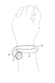
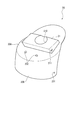
図1は本実施形態に係る腕時計の使用状態を示す斜視図であり、図2は本実施形態の腕時計の側面図である。本実施形態の腕時計は、外装ケース10と、外装ケース10に着脱可能にねじで固定される連結部材20と、連結部材20により外装ケース10に連結されるバンド部材30と、バンド部材30の端部に固定されるパーツ35とを備えている。
本実施形態の時計のバンドは、バンド部材30とパーツ35とを有して全体として略環状に構成されたバングルタイプとされ、腕の周りにほぼ沿って湾曲している。
外装ケース10および連結部材20は、バンド部材30の湾曲形状に連続して湾曲している。これらのケース本体11および連結部材20の湾曲方向を図2にRで示す。
FIG. 1 is a perspective view showing a usage state of a wristwatch according to the present embodiment, and FIG. 2 is a side view of the wristwatch of the present embodiment. The wristwatch of this embodiment includes an
The watch band of the present embodiment is a bangle type that has a
The
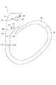
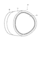
図4は、バンド部材30の斜視図である。バンド部材30は、樹脂製などの任意の材質で形成された断面略楕円形の芯材31と、この芯材31に巻かれた表皮材32とを備えている。
芯材31は、長さ方向にC字状に湾曲して形成されている。芯材31の一端部には連結部材20に固定される直方体状の凸部311が形成され、芯材31の他端部にはパーツ35取付用の孔312が形成されている。この芯材31の内周部には、周方向に沿って溝310が形成されている。
凸部311には、図示しないばね棒が挿通される孔311Aが形成されている。
FIG. 4 is a perspective view of the
The
The
表皮材32は、革、布、樹脂製シートなどの柔軟性を有する任意の材質で形成され、芯材31との間に接着剤が介在した状態で凸部311および孔312の近傍を除く芯材31の表面略全体に沿って設けられている。
表皮材32の端縁部同士は、芯材31の溝310に対応する位置で、絹、綿、樹脂繊維などの適宜の材質から形成された糸34によって縫い合わせられている。
The
The edge portions of the
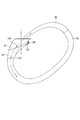
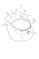
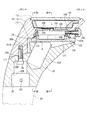
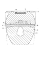
図5は、外装ケース10および連結部材20の斜視図であり、図6は、外装ケース10および連結部材20の平面図である。また、図7は、外装ケース10を図5とは反対側から見た斜視図である。そして、図8は、外装ケース10および連結部材20の縦断面図である。
外装ケース10は、図8に示すように、時計体としてのムーブメント100が設けられるケース本体11と、裏蓋12と、風防ガラス13とを有している。風防ガラス13はケース本体11の開口部に直接接着されている。
FIG. 5 is a perspective view of the
As shown in FIG. 8, the
本実施形態のムーブメント100は、文字板101および指針102により時刻が表示されるアナログ表示式の電子時計となっているが、搭載されるムーブメントの種類はこれに限らず、時刻表示部として液晶パネル等を備えたディジタル表示式の電子時計であってもよい。また、電子制御式機械時計や機械時計であってもよい。
The
ムーブメント100の外周部とケース本体11との間には、ムーブメント100固定用の筒状の枠体103が設けられ、ムーブメント100の6時方向には巻真104およびりゅうず105が設けられている。また、ムーブメント100における裏蓋12に対向する部分には、電池106が収納されている。
ここで、ムーブメント100は、文字板101および指針102を有する時刻表示部と裏蓋12とを結ぶムーブメント100の軸方向Sがケース本体11の湾曲方向R(図2)に対して交差した向きとなるようにケース本体11に設けられている。
A
Here, the
ケース本体11は、図5に示すようにムーブメント100の軸方向Sに対して偏心した略筒状に形成されており、ケース本体11における12時側の部分は風防ガラス13側から連結部材20側に向かって次第に外側に膨出している。また、ケース本体11における6時方向上面側の部分は、りゅうず105の位置よりも外側に突出している。
なお、ケース本体11の内側には、図8に示すように文字板101の外周縁部を隠す見切り115が設けられている。
As shown in FIG. 5, the
In addition, inside the case
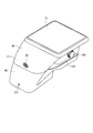
ケース本体11における裏蓋12の周りの部分は、図7に示すように裏蓋12に対して高さ方向に突出したケース本体突出部111とされている。
ケース本体突出部111における12時側の部分は3時側および9時側の部分に比べて高くなっており、この12時側の部分には裏蓋12と交差する方向に沿って2つのねじ孔111Aが形成されている。また、ケース本体突出部111における3時方向および9時方向のそれぞれの近傍の位置には、裏蓋12に沿った方向にねじが挿通される孔111Bが形成されている。
また、ケース本体11における6時方向の部分には、裏蓋12の外周部の一部が挿入される切欠113が形成されている。
A portion around the
The 12 o'clock side portion of the case
In addition, a
裏蓋12は、図7に示すように、円形状の裏蓋本体121と、裏蓋本体121の外周部の一部に連設され裏蓋本体121から立ち上がる段差部122とを有している。段差部122は、ケース本体11の切欠113からケース本体11の外側に露出しており、段差部122とケース本体11との間にはこじあけ口122A(図8)が形成されている。
また、裏蓋本体121の裏側には、図8のIX-IX線断面図である図9に示すように、ケース本体11の開口部114に嵌合するダボ123が形成されている。このダボ123は、裏蓋本体121の外周縁部に沿って、6時方向と12時方向とを除いた部分に形成されている。ケース本体11の開口部114と裏蓋本体121との間にはリング状のゴム製パッキン124が介装されている。
As shown in FIG. 7, the
Further, a
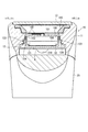
図10は、連結部材20の斜視図である。連結部材20は、外装ケース10側からバンド部材30側に向かって次第に縮径している。連結部材20の上面部20Aは、ケース本体突出部111(図7)および裏蓋12の段差部122(図7)に対向し、外装ケース10の外形とスムースに連続している。
連結部材20の上面部20Aには、ケース本体突出部111の内側に挿入された状態で裏蓋12に対向する直方体状の連結部材突出部21が形成されている。この連結部材突出部21と裏蓋12とは、図8、図9に示すように隙間Aを挟んで近接する。
連結部材突出部21には、図10に示すように軽量化用の孔210が形成されているとともに、ケース本体突出部111に形成された各孔111B(図7)にそれぞれ対応するねじ孔である第1固定孔211が形成されている。この第1固定孔211にはそれぞれ、図8のXI-XI線断面図である図11に示すように、固定部材としてのねじ25が孔111Bを介して挿入される。
FIG. 10 is a perspective view of the connecting
The
As shown in FIG. 10, the connecting
連結部材20の下端部20Bは、バンド部材30の断面形状と同様の形状に形成されており、バンド部材30の外形とスムースに連続している。
また、連結部材20の下端部20Bには、図8に示すように、バンド部材30側から外装ケース10側に向かって窪む凹部22が形成されている。
凹部22の内周部には、段差22Aが設けられており、凹部22における段差22Aの位置までバンド部材30の凸部311(図3)が挿入される。凹部22におけるバンド部材30の孔311A(図4)の両端側にそれぞれ対応する位置には、バンド固定孔231が形成されている。
そして凹部22の底部22Bには、上面部20Aまで貫通する2つの第2固定孔232が形成されている。これらの第2固定孔232にはそれぞれ、固定部材としてのねじ26が挿通される。
The
Moreover, as shown in FIG. 8, the
A
In the bottom 22B of the
以上説明した外装ケース10と、連結部材20と、バンド部材30とを組み立てる際には、図8のように外装ケース10における裏蓋12が設けられた側に連結部材20を配置し、ケース本体突出部111および裏蓋12の段差部122が連結部材20の上面部20Aに当接した状態とする。この状態で連結部材20とケース本体11とをねじ26およびねじ25(図11)によって固定する。具体的には、図8のように連結部材20の第2固定孔232からねじ26を挿入してケース本体11のねじ孔111Aにねじ込む。また、図11のようにケース本体11の外周部からねじ25を挿入して連結部材20の第1固定孔211にねじ込む。
When assembling the
次に、連結部材20にバンド部材30(図4)を固定する。なお、バンド部材30の芯材31には既に表皮材32が巻き付けられて縫合されているものとする。このバンド部材30の凸部311の孔311Aにばね棒(不図示)を挿通した状態とし、バンド部材30の凸部311を連結部材20の凹部22(図8)に挿入することにより、バンド部材30が連結部材20に固定される。そしてバンド部材30にパーツ35(図2)を連結することにより、本実施形態の時計の組立が完了する。この時計を図1のように腕に装着する際には、バンド部材30およびパーツ35で形成される環を内側から外側に拡げながら環の中に腕を通せばよい。
Next, the band member 30 (FIG. 4) is fixed to the connecting
ここで、図8のように裏蓋12に隙間Aを挟んで連結部材突出部21が対向しているため、時計を落としたりぶつけたりした際に、連結部材突出部21が裏蓋12の度当たりとなる。このため、裏蓋12がケース本体11から外れにくい。
Here, as shown in FIG. 8, the connecting
一方、電池交換時などに裏蓋12を開ける際には、まず、バンド部材30と連結部材20とを固定するばね棒(不図示)を外し、連結部材20の凹部22からバンド部材30の凸部311を抜き出す。この後、連結部材20と外装ケース10とを固定するねじ25およびねじ26を外し、こじあけ口122A(図8)から治具を挿入して裏蓋12をこじあけることにより、ダボ123(図9)がケース本体11から外れる。
On the other hand, when the
本実施形態によれば、次のような効果が得られる。
(1)連結部材20が外装ケース10とバンド部材30との間に介在するので、外装ケース10とバンド部材30とが連続的な形状に連結されていても外装ケース10の裏蓋12近傍はそれほど細くならない。すなわち、外装ケース10と連結部材20とを連続した形状に連結しつつ、連結部材20が外装ケース10から取り外された状態において治具により裏蓋12を容易に開閉できる。
According to this embodiment, the following effects can be obtained.
(1) Since the connecting
(2)外装ケース10とバンド部材30とが連結された状態で裏蓋12に連結部材20が対向し、落下衝撃時などに裏蓋12に直接負荷が掛かりにくいため、裏蓋12が外装ケース10から外れにくい。これにより、衝撃に対する信頼性を確保できる。
また、裏蓋12が省スペースなダボ固定構造とされているため、ケース本体11が大径化しない。このため、ケース本体11からバンド部材30にかけて連続した形状とすることを容易にできる。
(2) Since the connecting
Further, since the
(3)ケース本体11やバンド部材30の形状が変わった場合に、ケース本体がバンド部材に直接連結される構造ではケース本体における連結部やバンド部材の端部の形状を変更する必要があるのに対して、本実施形態では連結部材20の形状を変更すればよいことから、モデル展開を促進できる。
(3) When the shape of the case
(4)ケース本体11にバンド部材30の固定部を形成するよりも連結部材20にバンド部材30の固定部(凹部22など)を形成する方が容易なため、バンド部材30の取付を容易にできる。
(4) Since it is easier to form the fixing part (such as the recess 22) of the
(5)ケース本体11および連結部材20がバンド部材30の湾曲形状に連続して湾曲しているため、時計の外観意匠性を向上させることができる。
(5) Since the case
(6)連結部材20が外装ケース10側からバンド部材30側に向かって次第に縮径していることにより、連結部材20を介して外装ケース10とバンド部材30とを連続した形状に容易に連結することができる。
(6) Since the connecting
(7)ムーブメント100の軸方向Sがケース本体11の湾曲方向Rに対して交差しており、文字板101および指針102が腕に沿った方向に対して上側に向いているので、時刻の視認性を向上させることができる。
(7) Since the axial direction S of the
(8)裏蓋12の段差部122がケース本体11の切欠113から外部に露出しているので、裏蓋12をこじあけ易い。ここで、段差部122が露出する位置は腕に対向する側(6時方向)であって目立たないため、外観意匠を良好にできる。
(8) Since the stepped
(9)連結部材突出部21と、この連結部材突出部21には対向しないケース本体突出部111とにねじ25を挿入することにより、ケース本体11と連結部材20とを容易に固定できる。
そのうえ、これらの連結部材突出部21とケース本体突出部111とが固定された状態において連結部材突出部21が裏蓋12に近接するため、耐衝撃性を向上させることができる。
(9) The case
In addition, since the connecting
(10)連結部材20とケース本体11とを固定するねじ26が挿入される凹部22にバンド部材30の凸部311が挿入されており、連結部材20の凹部22が連結部材20およびケース本体11の連結と、連結部材20およびバンド部材30の連結とに兼用されるので、スペース効率を高くできる。
(10) The
(11)バンド部材30の端部に凸部311が形成され、連結部材20におけるバンド部材30側の端部に凹部22が形成されることにより、バンド部材30の表皮材32の表面にねじが露出することなく、バンド部材30と連結部材20とを固定することが可能となる。つまり、芯材31への表皮材32の巻きつけ後に、バンド部材30と連結部材20とを固定することが可能となるので、作業性が良くなる。
(11) The
(12)連結部材20とケース本体11とは、裏蓋12にほぼ沿った方向に設けられるねじ25と、裏蓋12に交差する方向に設けられるねじ26とによって二方向で固定されるため、耐衝撃性をより高くできる。
(12) Since the connecting
〔本発明の変形例〕
本発明は前記実施形態には限定されず、本発明の課題を解決しうる範囲で各種の改良および変形が可能である。
前記実施形態では、図11のように2本のねじ25によって連結部材20とケース本体11とが固定されていたが、連結部材20とケース本体11との固定部材はねじに限らない。例えば、図12のようにケース本体11と連結部材20とに形成された貫通孔40に設けられるピン41および断面C字状のパイプ42とによって連結部材20とケース本体11とが固定されていてもよい。パイプ42は貫通孔40におけるケース本体11の一端部に配置されており、このパイプ42内にピン41が圧入されることにより、ピン41およびパイプ42が貫通孔40内に固定される。
また、図13のように連結部材20とケース本体11とがねじピン43によって固定されていてもよい。
[Modification of the present invention]
The present invention is not limited to the above-described embodiment, and various improvements and modifications can be made within the scope of solving the problems of the present invention.
In the above embodiment, the connecting
Further, the connecting
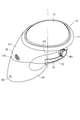
図14に、前記実施形態とは異なる形状の外装ケース45および連結部材46を示す。本例の外装ケース45および連結部材46は断面略四角形状とされている。これらの外装ケース45および連結部材46の構造はそれぞれ、前記実施形態の外装ケース10および連結部材20の構造と略同様に構成されているため、説明を省略する。なお、連結部材46には、断面四角形状のバンド部材が連結されることが好ましい。これにより、前記実施形態の時計と同様に、時計全体が連続した湾曲形状とされるため、外観意匠性を向上させることができる。
FIG. 14 shows an
前記実施形態における裏蓋固定構造はダボ食いつけ構造であったが、裏蓋の固定構造はこれに限定されず、任意の固定構造を採用できる。本発明では外装ケースとバンドとの間に連結部材が介在することにより、裏蓋がケースの奥に潜り込むほどケースが細くならず、裏蓋を開けるための治具を挿入するスペースが確保されるから、ケース本体の開口部に形成された雌ネジにねじ込まれるスクリュー裏蓋固定構造の採用も可能である。スクリュー裏蓋の外周縁部には治具係合用の溝が形成されており、この溝に治具を係合させて裏蓋を回転させることにより、裏蓋の開閉が行える。
また、裏蓋がねじによってケース本体に固定される構造としてもよい。この場合、ねじを立てるスペースの分、ケース本体が大径となるが、連結部材を適宜な長さとして外装ケース側からバンド側に縮径した形状とすることにより、外装ケースからバンドまでスムースに連続した形状とすることが可能となる。
The back cover fixing structure in the embodiment is a dowel biting structure, but the back cover fixing structure is not limited to this, and any fixing structure can be adopted. In the present invention, since the connecting member is interposed between the exterior case and the band, the case does not become so thin that the back cover goes into the back of the case, and a space for inserting a jig for opening the back cover is secured. Therefore, it is possible to employ a screw back cover fixing structure that is screwed into a female screw formed in the opening of the case body. A groove for engaging a jig is formed in the outer peripheral edge of the screw back cover, and the back cover can be opened and closed by engaging the jig in this groove and rotating the back cover.
Moreover, it is good also as a structure where a back cover is fixed to a case main body with a screw. In this case, the case body has a large diameter corresponding to the space for raising the screw, but by connecting the connecting member to an appropriate length and reducing the diameter from the outer case side to the band side, the outer case to the band can be smooth. A continuous shape can be obtained.
以上、本発明を実施するための最良の構成について具体的に説明したが、本発明は、これに限定されるものではない。すなわち、本発明は、主に特定の実施形態に関して特に図示され、かつ、説明されているが、本発明の技術的思想および目的の範囲から逸脱することなく、以上述べた実施形態に対し、形状、材質、数量、その他の詳細な構成において、当業者が様々な変形および改良を加えることができるものである。
上記に開示した形状、材質などを限定した記載は、本発明の理解を容易にするために例示的に記載したものであり、本発明を限定するものではないから、それらの形状、材質などの限定の一部もしくは全部の限定を外した部材の名称での記載は、本発明に含まれるものである。
Although the best configuration for carrying out the present invention has been specifically described above, the present invention is not limited to this. That is, the invention has been illustrated and described primarily with respect to particular embodiments, but may be configured for the above-described embodiments without departing from the scope and spirit of the invention. Various modifications and improvements can be made by those skilled in the art in terms of materials, quantity, and other detailed configurations.
The description limited to the shape, material, etc. disclosed above is an example for easy understanding of the present invention, and does not limit the present invention. The description by the name of the member which removes a part or all of the limitation is included in the present invention.
10・・・外装ケース、11・・・ケース本体、12・・・裏蓋、13・・・風防ガラス、20B・・・下端部、20A・・・上面部、20・・・連結部材、21・・・連結部材突出部、22・・・凹部、22A・・・段差、22B・・・底部、30・・・バンド部材、31・・・芯材、32・・・表皮材、34・・・糸、35・・・パーツ、40・・・貫通孔、41・・・ピン、42・・・パイプ、43・・・ピン、45・・・外装ケース、46・・・連結部材、100・・・ムーブメント、101・・・文字板(時刻表示部)、102・・・指針(時刻表示部)、103・・・枠体、104・・・巻真、106・・・電池、111・・・ケース本体突出部、111A・・・ねじ孔、111B・・・孔、113・・・切欠、114・・・開口部、121・・・裏蓋本体、122A・・・口、122・・・段差部、123・・・ダボ、124・・・ゴム製パッキン、210・・・孔、211・・・第1固定孔、231・・・バンド固定孔、232・・・第2固定孔、310・・・溝、311A・・・孔、311・・・凸部、312・・・孔、R・・・湾曲方向、S・・・軸方向。
DESCRIPTION OF
Claims (8)
前記裏蓋に対向した状態で前記外装ケースに着脱可能に固定される連結部材と、
前記連結部材を介して前記外装ケースに連結されるバンドと、を備える
ことを特徴とする時計。 A case body provided with a watch body, and an exterior case having a back cover;
A connecting member that is detachably fixed to the exterior case in a state of facing the back cover;
And a band connected to the exterior case via the connecting member.
前記裏蓋は、前記ケース本体の開口部に嵌合するダボを有する
ことを特徴とする時計。 The timepiece according to claim 1,
The back cover includes a dowel that fits into an opening of the case body.
前記バンドは、腕の周りにほぼ沿って湾曲し、
前記ケース本体および前記連結部材は、前記バンドの湾曲形状に連続して湾曲している
ことを特徴とする時計。 The timepiece according to claim 1 or 2,
The band is curved substantially along the arm;
The case main body and the connecting member are continuously curved in the curved shape of the band.
前記連結部材は、前記外装ケース側から前記バンド側に向かって次第に縮径している
ことを特徴とする時計。 The timepiece according to any one of claims 1 to 3,
The timepiece in which the connecting member is gradually reduced in diameter from the outer case side toward the band side.
前記時計体が有する時刻表示部と前記裏蓋とを結ぶ前記時計体の軸方向は、前記ケース本体の湾曲方向に対して交差している
ことを特徴とする時計。 The timepiece according to claim 3 or 4,
A timepiece in which an axial direction of the timepiece connecting the time display portion of the timepiece and the back cover intersects a bending direction of the case main body.
前記裏蓋は、前記ケース本体の開口部に嵌合するダボを有し、
前記裏蓋の外周部の一部は、前記ケース本体の湾曲形状における内周側で前記ケース本体から露出している
ことを特徴とする時計。 The timepiece according to any one of claims 3 to 5,
The back cover has a dowel that fits into the opening of the case body,
A part of the outer peripheral portion of the back cover is exposed from the case main body on the inner peripheral side in the curved shape of the case main body.
前記連結部材には、前記裏蓋に向かって突出する突出部が形成され、
前記ケース本体における前記裏蓋の周りの少なくとも一部には、前記連結部材に向かって突出する突出部が形成され、
前記連結部材と前記ケース本体とは、前記裏蓋にほぼ沿った方向において前記連結部材の突出部と前記ケース本体の突出部とに挿入される固定部材によって固定されている
ことを特徴とする時計。 The timepiece according to any one of claims 1 to 6,
The connecting member is formed with a protruding portion that protrudes toward the back cover,
At least a part of the case body around the back cover is formed with a protruding portion that protrudes toward the connecting member,
The connecting member and the case main body are fixed by a fixing member inserted into the protruding portion of the connecting member and the protruding portion of the case main body in a direction substantially along the back cover. .
前記連結部材における前記バンド側の端部には、前記バンドの端部に形成された凸部が挿入される凹部が形成され、
前記連結部材と前記ケース本体とは、前記凹部の底部から前記ケース本体に向かって挿入される固定部材によって固定され、
前記連結部材と前記バンドとは、前記凹部に前記凸部が挿入された状態で前記連結部材と前記凸部とに挿入される固定部材によって固定されている
ことを特徴とする時計。 The timepiece according to any one of claims 1 to 7,
A concave portion into which a convex portion formed at the end portion of the band is inserted is formed at the end portion on the band side of the connecting member,
The connecting member and the case main body are fixed by a fixing member inserted from the bottom of the concave portion toward the case main body,
The connecting member and the band are fixed by a fixing member inserted into the connecting member and the convex portion in a state where the convex portion is inserted into the concave portion.
Priority Applications (1)
| Application Number | Priority Date | Filing Date | Title |
|---|---|---|---|
| JP2007249099A JP5119829B2 (en) | 2007-09-26 | 2007-09-26 | Timepiece with connecting member |
Applications Claiming Priority (1)
| Application Number | Priority Date | Filing Date | Title |
|---|---|---|---|
| JP2007249099A JP5119829B2 (en) | 2007-09-26 | 2007-09-26 | Timepiece with connecting member |
Publications (2)
| Publication Number | Publication Date |
|---|---|
| JP2009077898A JP2009077898A (en) | 2009-04-16 |
| JP5119829B2 true JP5119829B2 (en) | 2013-01-16 |
Family
ID=40653105
Family Applications (1)
| Application Number | Title | Priority Date | Filing Date |
|---|---|---|---|
| JP2007249099A Expired - Fee Related JP5119829B2 (en) | 2007-09-26 | 2007-09-26 | Timepiece with connecting member |
Country Status (1)
| Country | Link |
|---|---|
| JP (1) | JP5119829B2 (en) |
Family Cites Families (4)
| Publication number | Priority date | Publication date | Assignee | Title |
|---|---|---|---|---|
| JPS61129190U (en) * | 1985-01-31 | 1986-08-13 | ||
| JP2000346960A (en) * | 1999-06-03 | 2000-12-15 | Casio Comput Co Ltd | clock |
| JP3098803U (en) * | 2003-06-25 | 2004-03-18 | 永吉電脳股▲分▼有限公司 | Wristwatch containing a small storage device |
| JP2006201052A (en) * | 2005-01-21 | 2006-08-03 | Seiko Epson Corp | clock |
-
2007
- 2007-09-26 JP JP2007249099A patent/JP5119829B2/en not_active Expired - Fee Related
Also Published As
| Publication number | Publication date |
|---|---|
| JP2009077898A (en) | 2009-04-16 |
Similar Documents
| Publication | Publication Date | Title |
|---|---|---|
| JP3961320B2 (en) | Arm-mounted portable device with bangle type band | |
| KR0163059B1 (en) | Watch case with two adjacent shells | |
| JP2005098975A5 (en) | ||
| US7278783B1 (en) | Wristwatch and strap for timepiece | |
| JP3556680B2 (en) | Watch side | |
| US7404668B2 (en) | Timepiece | |
| JPH09501501A (en) | Wrist watch with replaceable band | |
| JP6299954B2 (en) | Pointer and clock | |
| JP5119829B2 (en) | Timepiece with connecting member | |
| JP5090110B2 (en) | Watch with a case that can be unfolded | |
| JP5831846B2 (en) | Band and watch | |
| US7399114B2 (en) | Timepiece having glass and edge member removable as a unit | |
| JP4186469B2 (en) | Wearable equipment | |
| US20070147184A1 (en) | Timepiece | |
| JP2003043165A (en) | Band mounting structure | |
| JP4415170B2 (en) | Band mounting structure and wrist device | |
| JP5397286B2 (en) | Watches | |
| JP2006234792A (en) | Watch movement holding structure and watch | |
| JP6338926B2 (en) | Band mounting structure and watch | |
| KR200346640Y1 (en) | Bouble-Faced Wristwatch | |
| RU176850U1 (en) | WRIST WATCH | |
| RU2664742C1 (en) | Wrist watch | |
| JPH10197660A (en) | Watch band mounting structure | |
| JP3163403U (en) | Push buckle for watch band, watch band and wrist watch provided with the same | |
| KR200174870Y1 (en) | A wrist watch |
Legal Events
| Date | Code | Title | Description |
|---|---|---|---|
| A621 | Written request for application examination |
Free format text: JAPANESE INTERMEDIATE CODE: A621 Effective date: 20100921 |
|
| TRDD | Decision of grant or rejection written | ||
| A01 | Written decision to grant a patent or to grant a registration (utility model) |
Free format text: JAPANESE INTERMEDIATE CODE: A01 Effective date: 20120925 |
|
| A01 | Written decision to grant a patent or to grant a registration (utility model) |
Free format text: JAPANESE INTERMEDIATE CODE: A01 |
|
| A977 | Report on retrieval |
Free format text: JAPANESE INTERMEDIATE CODE: A971007 Effective date: 20120928 |
|
| A61 | First payment of annual fees (during grant procedure) |
Free format text: JAPANESE INTERMEDIATE CODE: A61 Effective date: 20121008 |
|
| FPAY | Renewal fee payment (event date is renewal date of database) |
Free format text: PAYMENT UNTIL: 20151102 Year of fee payment: 3 |
|
| R150 | Certificate of patent or registration of utility model |
Free format text: JAPANESE INTERMEDIATE CODE: R150 |
|
| S531 | Written request for registration of change of domicile |
Free format text: JAPANESE INTERMEDIATE CODE: R313531 |
|
| R350 | Written notification of registration of transfer |
Free format text: JAPANESE INTERMEDIATE CODE: R350 |
|
| LAPS | Cancellation because of no payment of annual fees |