JP5118630B2 - System for ventricular pacing to adjust AV interval - Google Patents
System for ventricular pacing to adjust AV interval Download PDFInfo
- Publication number
- JP5118630B2 JP5118630B2 JP2008508904A JP2008508904A JP5118630B2 JP 5118630 B2 JP5118630 B2 JP 5118630B2 JP 2008508904 A JP2008508904 A JP 2008508904A JP 2008508904 A JP2008508904 A JP 2008508904A JP 5118630 B2 JP5118630 B2 JP 5118630B2
- Authority
- JP
- Japan
- Prior art keywords
- interval
- pacing
- mode
- ventricular
- implantable medical
- Prior art date
- Legal status (The legal status is an assumption and is not a legal conclusion. Google has not performed a legal analysis and makes no representation as to the accuracy of the status listed.)
- Active
Links
Images


Classifications
-
- A—HUMAN NECESSITIES
- A61—MEDICAL OR VETERINARY SCIENCE; HYGIENE
- A61N—ELECTROTHERAPY; MAGNETOTHERAPY; RADIATION THERAPY; ULTRASOUND THERAPY
- A61N1/00—Electrotherapy; Circuits therefor
- A61N1/18—Applying electric currents by contact electrodes
- A61N1/32—Applying electric currents by contact electrodes alternating or intermittent currents
- A61N1/36—Applying electric currents by contact electrodes alternating or intermittent currents for stimulation
- A61N1/362—Heart stimulators
- A61N1/365—Heart stimulators controlled by a physiological parameter, e.g. heart potential
- A61N1/368—Heart stimulators controlled by a physiological parameter, e.g. heart potential comprising more than one electrode co-operating with different heart regions
- A61N1/3682—Heart stimulators controlled by a physiological parameter, e.g. heart potential comprising more than one electrode co-operating with different heart regions with a variable atrioventricular delay
Description
本発明は包括的には埋め込み可能医療デバイスに関し、より具体的には、心臓ペーシングのための埋め込み可能医療デバイスに関する。 The present invention relates generally to implantable medical devices, and more particularly to implantable medical devices for cardiac pacing.
心臓ペーシングを提供する際に、心室の内因性伝導及び内因性脱分極を促進すること、及び心室ペーシングを低減するか又は最小限に抑えることが好ましい。内因性伝導を促進し、種々の度合いで成功に導くための種々のプロトコルが提供されている。たとえば、いくつかのモードでは、プログラムされたAV(房室)遅延が延長され、根底を成す伝導が内在する場合には、心室事象を検知するのに応じて、後続の心室ペーシングが抑制されるであろう。有用ではあるが、利用可能な最大間隔を従来どおりのペーシング方式の能力に合わせておかなければならないという点で、そのようなAV延長は制限される。すなわち、そのようなAV間隔は、たとえば、DDDモード又はDDDRモードの中で定義することができる。任意の所与の心周期において、心室活動が検知されないAV遅延の終わりに、心室ペーシングが送出されることになる。それゆえ、或る最大のAV遅延があり、それを超えると、所与の心周期において、心室ペーシングが安全に送出されないことがある。 In providing cardiac pacing, it is preferable to promote intrinsic conduction and intrinsic depolarization of the ventricles and to reduce or minimize ventricular pacing. Various protocols are provided to promote endogenous conduction and lead to success to varying degrees. For example, in some modes, if the programmed AV (atrioventricular) delay is prolonged and the underlying conduction is intrinsic, subsequent ventricular pacing is suppressed in response to detecting a ventricular event. Will. While useful, such AV extensions are limited in that the maximum available spacing must be matched to the capabilities of conventional pacing schemes. That is, such an AV interval can be defined in the DDD mode or the DDDR mode, for example. In any given cardiac cycle, ventricular pacing will be delivered at the end of the AV delay when no ventricular activity is detected. Therefore, there is some maximum AV delay beyond which ventricular pacing may not be delivered safely in a given cardiac cycle.
本発明のプロトコルによれば、且つ上記で援用された特許出願においてさらに詳細に記載されるように、心室事象が検知されない場合であっても、心室ペーシングを用いることなく、1つの心周期全体が良好に経過できるようにするモードが提供される。これは、所与の心周期中に、内因性伝導が起こる最大限の機会を与える。そのようなプロトコルはまとめて、「管理式心室ペーシング(商標)」(MPV(商標))又は「心室ペーシングプロトコル」(VPP)と呼ばれることがある。 In accordance with the protocol of the present invention and as described in further detail in the above-incorporated patent application, even if no ventricular event is detected, an entire cardiac cycle can be performed without using ventricular pacing. A mode is provided to allow good progress. This gives the greatest opportunity for intrinsic conduction during a given cardiac cycle. Such protocols may be collectively referred to as “managed ventricular pacing ™” (MPV ™) or “ventricular pacing protocol” (VPP).
実際に、心室ペーシングを提供しない所与のVPPによって、所与の患者が申し分なく動作することができる。すなわち、内因性伝導が常に存在するか、又はVPPによって容認されるほど稀にしか欠如しない限り、所与の患者が、AAIRモード、AAIモード、ADIモード又はADIRモードにあるかのように効果的に振舞うことができる。他の患者、たとえば、完全心ブロックを起こしている患者は、ペースメーカに依存し、一定の心室ペーシングを必要とすることがある。そのような場合には、そのペーシングは生きる上で欠くことができないので、VPPが心室ペーシングを低減する機会はない。最後に、2つの極端な状態の間で絶えず変化する患者がいる。これらの患者は、心室ペーシングを必要とするときもあるが、他のときには、正常な間隔又は延長された間隔において、内因性伝導を示すであろう。 Indeed, a given VPP that does not provide ventricular pacing allows a given patient to perform satisfactorily. That is, as long as intrinsic conduction is always present or rarely lacking to be tolerated by VPP, it is effective as if a given patient is in AAIR, AAI, ADI or ADIR mode Can behave. Other patients, such as those who have a complete heart block, depend on the pacemaker and may require constant ventricular pacing. In such cases, there is no opportunity for the VPP to reduce ventricular pacing, since the pacing is vital to life. Finally, there are patients that constantly change between two extreme conditions. These patients may require ventricular pacing, but at other times they will show intrinsic conduction at normal or extended intervals.
絶えず変化する患者では、VPPは、許容可能なときには心房ペーシングモードで動作することになり、心室ペーシングが必要とされるときには、二腔ペーシングモードで動作するであろう。本説明は概要として提供されており、限定することは意図していないものと理解されたい。すなわち、VPPは、場合によって、モードを切り替えることもあれば、心房を基にする機能及び二腔を基にする機能の両方を達成する単一のモードを含むことにある。したがって、説明上、心房モード又は二腔モード(VPPを参照)は、与えられる機能を指示しており、実際のモード状態/切替を含むか、又は両方の態様を含んだ単一モードを用いるVPPの機能状態かのいずれかを含む。さらに、心房ペーシングモードは単に、一般的に心室ペーシングが(所与の周期中)提供されないことを意味しており、二腔モードは、心室ペーシングが(所与の周期中)利用可能であることを意味する。したがって、本明細書において用いられるときに、これらのモードを区別することは、三腔ペーシング構成、四腔ペーシング構成、又は他の多部位ペーシング構成を除外するものではない。 In a constantly changing patient, the VPP will operate in an atrial pacing mode when acceptable, and in a dual chamber pacing mode when ventricular pacing is required. It should be understood that this description is provided as a summary and is not intended to be limiting. That is, the VPP may be switched between modes, and may include a single mode that achieves both an atrial-based function and a dual-chamber based function. Thus, for purposes of explanation, atrial mode or dual chamber mode (see VPP) indicates the function to be provided and includes a real mode state / switch or a VPP using a single mode that includes both aspects. One of the functional states. Furthermore, atrial pacing mode simply means that ventricular pacing is generally not provided (during a given cycle), and dual chamber mode is that ventricular pacing is available (during a given cycle). Means. Thus, as used herein, distinguishing between these modes does not exclude three-chamber pacing configurations, four-chamber pacing configurations, or other multi-site pacing configurations.
上記で示されたように、種々の患者が、心室ペーシングを必要とすること及び必要としないことの間で絶えず変化するであろう。その場合に、二腔ペーシングモードへの変更は、一般的には、永続的であることは期待されない。すなわち、そのデバイスは、周期的に伝導性検査を実行して、内因性伝導が存在するか否か、それゆえ、心房ペーシングモードに戻るのを促進するか否かを判定するであろう。 As indicated above, various patients will constantly change between requiring and not requiring ventricular pacing. In that case, the change to the dual chamber pacing mode is generally not expected to be permanent. That is, the device will periodically perform a conductivity test to determine whether there is intrinsic conduction and therefore facilitates returning to the atrial pacing mode.
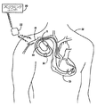
図1は、本発明に従って用いられるようになっている埋め込み可能医療デバイスシステムの図である。図1に示される医療デバイスシステムは、患者12に埋め込まれているペースメーカのような、埋め込み可能医療デバイス(「IMD」)10を含む。IMD10はペースメーカにすることができるか、又はIMD10は埋め込み可能カーディオバータ−ディフィブリレータ(ICD)等のカーディオバージョン能力及び/又はディフィブリレーション能力を含むこともできるものと理解されたい。IMD10は、気密封止され、生物学的に不活性の外部ケーシング内に収容され、ケーシングそのものは導電性であり、ペーシング/検知回路内の不関電極としての役割を果たすことができる。図1においてまとめて参照番号14で特定される、1つ又は複数のペースメーカリード線が、従来どおりにIMD10に電気的に接続され、静脈18を介して、患者の心臓16の中まで延在する。リード線14の概ね遠位端付近には、電気心臓信号を受信し、且つ/又は心臓16に電気的なペーシング刺激を送出するための1つ又は複数の露出した導電性電極が配置される。心臓16の心房内及び/又は心室内にその遠位端が位置するようにリード線14を埋め込むことができることは当業者には理解されよう。
FIG. 1 is a diagram of an implantable medical device system adapted for use in accordance with the present invention. The medical device system shown in FIG. 1 includes an implantable medical device (“IMD”) 10, such as a pacemaker that is implanted in a
IMD10は、図1において、通常胸筋下に画定される「ポケット」内に埋め込まれるように示されており、リード線14は脈管構造を通って心臓の中まで延在する。代替的に、IMD10は、皮下に埋め込まれるデバイスとして具現化することができ、そのデバイスは心臓16から離れて位置する電極を有するか、又は心臓16の内部又は外部まで延在するリード線を備えるかのいずれかである。
The
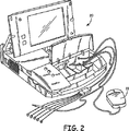
また図1には、後にさらに詳細に説明されることになる、アップリンク通信チャネル及びダウンリンク通信チャネルを介して、埋め込み式デバイス10と非侵襲的に通信するための外部プログラミングユニット20も示される。従来の医療デバイスプログラミングシステムに従って、IMD10とプログラマ20との間の双方向通信を容易にするために、プログラミングユニット20にプログラミングヘッド22が関連付けられる。数多くの既知の埋め込み可能デバイスシステムでは、図1に示されるようなプログラミングヘッドが、そのデバイスの埋め込み部位上の、患者の人体の直ぐ近くに配置され(通常は、皮膚接触の2〜3インチ以内)、当該技術分野における一般的な手法に従って、ヘッド内の1つ又は複数のアンテナが、埋め込み式デバイスの気密封入体内に配置されるか、又はデバイスのコネクタブロック内に配置されるアンテナにRF信号を送信すると共にアンテナからRF信号を受信できるようにする。その代わりに、又はそれに加えて、プログラミングユニット20との通信は、IMD10内に適切な送受信器を組み込むことによって、さらに長距離にわたって、RF伝送を通じて行われる。図2は、現在開示されている本発明によるプログラミングユニット20の一実施形態の斜視図である。
Also shown in FIG. 1 is an
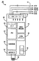
図3は、IMD10内のパルス発生器を構成する電子回路機構の一実施形態のブロック図である。一次刺激制御回路25が、IMDのペーシング機能及び検知機能を制御する。たとえば、図2の刺激制御回路25は、検知増幅器回路24と、刺激パルス出力回路26と、水晶クロック28と、ランダムアクセスメモリ及びリードオンリーメモリ(RAM/ROM)ユニット30と、中央演算装置(CPU)32とを備える。またIMD10は、内部通信回路34も備えており、IMD10が外部プログラマ/制御ユニット20と通信できるようにする。
FIG. 3 is a block diagram of one embodiment of the electronic circuitry that constitutes the pulse generator in the
続けて図3を参照すると、IMD10は、コネクタブロックアセンブリ11において、1つ又は複数のリード線14に接続されており、それらのリード線は、埋め込まれるときに、経静脈的に、埋め込み部位と患者の心臓16との間に延在する。電気的には、リード線の導体とパルス発生器10の内部電気部品との間の接続は、リードインターフェース回路19によって容易に実施することができ、リードインターフェース回路19は、マルチプレクサのようにして、たとえば、心房の先端電極導体ATIP及びリング電極導体ARING、並びに心室の先端電極導体VTIP及びリング電極導体VRINGを含む、リード線14内の種々の導体と、IMD10の個々の電気部品との間に必要な接続を選択的且つ動的に確立するための役割を果たす。
With continued reference to FIG. 3, the IMD 10 is connected to one or more leads 14 in the connector block assembly 11, which leads are implanted intravenously with the implantation site when implanted. It extends between the patient's
図4は、Marker Channel(登録商標)図でADI/RモードのIMD動作を示すラダー図である。NBGコードの助けを借りて、最新技術に精通している人は、以下のことを理解することができるであろう。最初に位置する文字(A)は、心房検知事象が存在しない場合に、ペースメーカ(又は他の埋め込み式デバイス)が心房をペーシングすることを意味する。第2の文字(D)は、ペースメーカが二腔、すなわち心房及び心室の両心腔において検知することを意味する。第3の文字(I)は、いずれかの心腔において検知すると、その特定の心腔においてペーシングが抑制されることを意味する。最後の文字Rは、そのデバイスがレート応答性であり、すなわち圧電結晶、加速度計、換気量等のような人工センサに応答して、心房レートを変更できることを意味する。 FIG. 4 is a ladder diagram showing the IMD operation in the ADI / R mode in the Marker Channel (registered trademark) diagram. A person familiar with the latest technology with the help of the NBG code will be able to understand: The first letter (A) means that the pacemaker (or other implantable device) paces the atrium when there is no atrial sensing event. The second letter (D) means that the pacemaker senses in two chambers, both the atrium and the ventricle. The third letter (I) means that when detected in any heart chamber, pacing is suppressed in that particular heart chamber. The last letter R means that the device is rate responsive, that is, it can change the atrial rate in response to artificial sensors such as piezoelectric crystals, accelerometers, ventilation, etc.
ADI/Rモードにおける動作は、以下のように、ラダー図で示される。心房ペーシング(又は検知)事象1は、プログラムできない自己調整(たとえば、100〜150ミリ秒)ブランキング時間4を開始し、それに、自己調整(auto-adjusting)心房感度(図示せず)が続く。検知回路(図3を参照)が、心室検知事象2が生じているか否かを判定する。検出された場合には、タイミング回路部(図3を参照)は、VA間隔9を開始する。他のタイミング、ブランキング時間、及び不応期は以下の目的を果たす。プログラム可能な心室ブランキング時間8は、「クロストーク」とも呼ばれることがある、心室チャネルにおいて心房ペース1が検知されるのを防ぐ。心室検知事象2は、120ミリ秒の事後心室心房ブランキング(PVAB)時間6を開始し、それに自己調整心房感度が続く。PVAB6は、「遠方場R波検知」と呼ばれる、心房チャネルにおいてR波又はT波が検知されるのを防ぐという目的を果たす。心室検知事象2も、100ミリ秒の心室ブランキング7を開始し、それに自己調整心室感度が続く。この時間は、心室出力パルス又は心室脱分極そのものが検知されるのを防ぐという目的を果たす。R波2に、再分極、すなわちT波3が続く。検知回路(図3を参照)によって検出される心室事象2は、タイミング回路部に信号を送出してVA間隔9を開始し、結果として、次の心房ペーシング周期が開始される。
The operation in the ADI / R mode is shown by a ladder diagram as follows. Atrial pacing (or sensing)
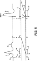
このモードが、完全な、又は或る程度損なわれていないAV伝導を有する洞不全患者で主に用いられることを考慮に入れると、ADI/Rモードの場合に図示されるような、このタイプの動作は、臨床医又は医師が発生することを予想する動作である。完全なAV伝導の存在時には、それが延長される場合であっても、ペースメーカはADI/R動作/モードを保持するであろう。検知される心室事象は、心周期の大部分(すなわち、PQRST)において生じるであろう。図5は、1心周期又は数心周期にわたって患者が一過性AVブロックを発症する場合に、何が生じることになるかを教示する。 Taking into account that this mode is mainly used in patients with sinus failure with complete or somewhat intact AV conduction, this type of as illustrated in the case of ADI / R mode An action is an action that a clinician or physician expects to occur. In the presence of full AV conduction, the pacemaker will retain ADI / R operation / mode even if it is extended. Detected ventricular events will occur during the majority of the cardiac cycle (ie, PQRST). FIG. 5 teaches what will happen if a patient develops a transient AV block over one or several cardiac cycles.
図5は、患者が一過性AVブロックを発症する場合のコミット(committed)DDI/R動作のラダー図である。コミットDDI/R動作の目的は、AVブロックの存在時に、心室支援を保持することである。簡単に説明すると、埋め込み式デバイスは、1つの周期の間、好ましいADI/RからコミットDDI/Rにモードを切り替える。 FIG. 5 is a ladder diagram of a committed DDI / R operation when a patient develops a transient AV block. The purpose of the commit DDI / R operation is to maintain ventricular support in the presence of AV blocks. Briefly, the implantable device switches mode from the preferred ADI / R to the commit DDI / R for one period.
コミットDDI/Rのタイミングは以下のとおりである。DDI/Rモード(DDI/Rを付される第3のペーシング周期)では、第2の心房ペーシング事象と第3の心房ペーシング事象との間でいかなる心室事象も検知されないことに起因して、P波がペーシングされた後に、AV間隔5が短い80ミリ秒に設定される。この短いAV間隔5の目的は、ペーシングされたR波13において終了する心室ペーシングパルスと、前にペーシングされた心房事象から伝導が遅れている任意の潜在的な内因性R波が、競合しないようにすることである。そのような内因性R波が存在するものと仮定すると、通常は、心室出力パルスのタイミングの結果として、心室ペーシングパルスが内因性の伝導されるR波の絶対不応期に入ることになり、結果として偽性融合収縮(pseudo-fusion beat)(図示せず)が生じる。一般的に「pacing on T」現象と呼ばれるような、心室ペーシングパルスが心室の相対不応期に入る場合に、この動作は、心室頻脈の発症を防ぐことを意図している。
The timing of commit DDI / R is as follows. In the DDI / R mode (the third pacing period marked DDI / R), P is due to no ventricular event being detected between the second atrial pacing event and the third atrial pacing event. After the wave is paced,
図5のタイミングで続けると、ペーシングされたR波13は、120ミリ秒の心室ブランキング時間7を開始し、それに自己調整心室感度(図示せず)が続く。ペーシングされたR波13も、120ミリ秒のPVAB6を開始し、それに自己調整心房感度(図示せず)が続く。一過性AVブロックが自己修正し、ペーシングされたR波が検出されるものと仮定すると、図4に示されるように、次のペーシングP波又は検知P波で、好ましいADI/Rが再開する。
Continuing at the timing of FIG. 5, the
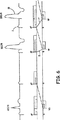
図6は、患者が2周期以上にわたって持続するAVブロックを発症する場合の一実施形態におけるペーシング動作を示すラダー図である。本発明の好ましい実施形態によれば、拍動が一度見逃された(すなわち、Vsがない)だけでは、モードが切り替えられることなく、特に相対的に信頼性があるAV伝導が存在する場合にはそうであることに留意されたい。DDI/Rに1周期だけモードを切り替えた後に、VA間隔9はタイムアウトし、結果として、心房ペーシング事象1が生じる。AV伝導を促進しようと試みるために、非常に長い間隔(たとえば、400ミリ秒又はセンサによって指示されたAV間隔の65%まで)17が用いられる。しかしながら、第1の周期(ADI/Rを付される)において示されるように、AV間隔17が検知された内因性R波によって中断されない場合には、ペースメーカは直ちにDDD/Rモードに切り替わる。内因性R波が検知される場合には、デバイスは、ADI/R動作(図示せず)に戻る。AV間隔がプログラムされているDDD/R動作は、検知された内因性R波が検出されるまで持続される。強制的にADI/R動作を回復しようとする試みが周期的に実行される(図7に示される)。心房頻脈が検出される場合には、DDI/Rモードにモードが切り替えられるであろう(図8を参照)。
FIG. 6 is a ladder diagram illustrating a pacing operation in one embodiment when a patient develops an AV block that lasts for two or more cycles. According to a preferred embodiment of the present invention, once the beat is missed (ie, there is no Vs), the mode is not switched, especially when there is relatively reliable AV conduction. Note that it is. After switching the mode to DDI / R for one cycle, the
図7は、持続DDD/R動作中にADI/R動作を回復するように周期的に試みることを示すラダー図である。上記のように、DDD/Rモードは、患者が、心拍依存性AVブロックで生じることがあるような、遷延性AVブロックを発症する場合には、持続動作モードになることがある。そのような場合には、デバイスは、プログラム可能な数のDDD/R周期後に、ADI/R1に戻るようにプログラムされることがある。その後、デバイスは、たとえば、心房ペース1後の23において、心室検知事象を探索する。検知された内因性R波が検出された場合には、ADI/R動作が直ちに再開される。心室検知事象が存在しない場合には、デバイスは、図7の第3の周期において示されるように、DDD/Rモードにおいて動作し続ける。
FIG. 7 is a ladder diagram illustrating periodically attempting to recover ADI / R operation during sustained DDD / R operation. As noted above, the DDD / R mode may become a continuous mode of operation when the patient develops a protracted AV block that may occur with a heart rate dependent AV block. In such cases, the device may be programmed to return to ADI / R1 after a programmable number of DDD / R periods. The device then searches for a ventricular detection event, for example, at 23 after
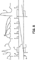
図8は、患者が心房頻脈を発症した場合のペーシング動作のラダー図である。洞不全患者は多くの場合に、心房頻脈、心房粗動又は心房細動のエピソードを有する。これらのエピソード中には、心室ペーシングレートが速い心房レートにも、症状を引き起こすほどの遅いレートにも同期しないように、ペーシング動作が実施されなければならない。 FIG. 8 is a ladder diagram of a pacing operation when a patient develops an atrial tachycardia. Sinus failure patients often have episodes of atrial tachycardia, atrial flutter or atrial fibrillation. During these episodes, a pacing operation must be performed so that the ventricular pacing rate is not synchronized to a fast atrial rate or a slow enough rate to cause symptoms.
図5では、ADI/Rモードにおいて動作している間に、デバイスがDDI/Rモードに切り替わることができることが言及された。DDI/Rモードによれば、心室が速い心房レートに同期できないようにするだけでなく、心室ペーシングレートがプログラムされた低い方のレートを下回らないようにすることができるので、心房頻脈の存在時にペーシングするのに非常に適している。それゆえ、図8に示されるように、心房頻脈が生じるときに、心室事象が伝導されることがない速い心房検知事象27でも、心室タイミング9には影響を及ぼさない。心室事象がないので、その動作は直ちにDDI/Rモードに切り替わる。心房頻脈の存在時に、V−V間隔9はタイムアウトし、プログラムされた低いレートよりも速いレートにおいて、又はDDI/Rモードにおいてセンサによって指示されるレートにおいて、ペーシングされたR波8が生じる。図8において示される動作は、心房頻脈が持続する限り続く。心房頻脈の終了時に、心臓が心房頻脈性不整脈からいかに回復したかによって、図4又は図7に示されるように、好ましいADI/Rが再開する。心房頻脈性不整脈が突然に終了する場合には、ADI/Rモードの迅速な回復が行われる(図4を参照)。しかしながら、心房頻脈性不整脈がゆっくり「鎮まる」場合には、DDD/Rペーシングの期間が存在することがあり、図7に示されるように、周期的にADI/Rペーシングに回復することが試みられる。
In FIG. 5, it was mentioned that the device can switch to DDI / R mode while operating in ADI / R mode. The presence of atrial tachycardia not only prevents the ventricle from synchronizing to the fast atrial rate, but also prevents the ventricular pacing rate from falling below the programmed lower rate, according to DDI / R mode. Very suitable for pacing sometimes. Therefore, as shown in FIG. 8, even a rapid
図9を包括的に参照すると、心室ペーシングプロトコルは、以下の態様の内1つ又は複数を含む。モードスーパーバイザが組み込まれ、モード変更に関連する広範な動作を制御する。モードスーパーバイザとして、ハードウエア、ソフトウエア又はファームウエアに基づくモジュールを用いることができる。モードスーパーバイザの一態様は、患者の心房−心室状態をモニタすると共に、必要なときに、従来のペーシングモード(すなわち、DDD/R及びDDI/R)への持続的なモード切替を呼び出すことによって介入することである。モードスーパーバイザは、一実施形態では、許容できる(又は「相対的に信頼性がある」)AV伝導状態と、許容できない(又は「相対的に信頼性がない」)AV伝導状態とを区別するために重要な意味を持つAV伝導許容比を定義するウェンケバッハパターンに従って、信頼性のないAV伝導を定義する。たとえば、4:3のAV伝導許容比であれば、4つの生理的心房事象毎に少なくとも3つの心室事象が存在する限り、好ましいADI/R動作が持続できるようになる。A事象とV事象との比が、予め定義された許容比未満になる場合には、従来のDDD/Rペーシングへの持続的な切替が生じるであろう。非生理的と分類される(すなわち、ARP内の)心房事象は、A:V比の計算において考慮されない。それにより、頻繁な非伝導の心房性期外収縮(PAC)の存在時に、不適切なDDD/Rへのモード切替が避けられる。 Referring generally to FIG. 9, the ventricular pacing protocol includes one or more of the following aspects. A mode supervisor is incorporated to control a wide range of operations related to mode changes. Modules based on hardware, software or firmware can be used as mode supervisors. One aspect of the mode supervisor is to monitor the patient's atrial-ventricular status and intervene by invoking continuous mode switching to conventional pacing modes (ie, DDD / R and DDI / R) when necessary. It is to be. The mode supervisor, in one embodiment, distinguishes between an acceptable (or “relatively reliable”) AV conduction state and an unacceptable (or “relatively unreliable”) AV conduction state. The unreliable AV conduction is defined according to the Wenkebach pattern that defines the AV conduction tolerance with significant significance to For example, a 4: 3 AV conduction tolerance ratio allows the preferred ADI / R behavior to continue as long as there are at least three ventricular events for every four physiological atrial events. If the ratio of A event to V event falls below a predefined tolerance ratio, a persistent switch to conventional DDD / R pacing will occur. Atrial events classified as non-physiological (ie, within ARP) are not considered in the calculation of the A: V ratio. This avoids inappropriate mode switching to DDD / R in the presence of frequent non-conducting atrial premature contractions (PACs).
信頼性のないAV伝導の存在時にDDD/Rペーシングを呼び出すと、モードスーパーバイザは直ちに、ADI/Rペーシングを回復しようと試みる役割を果たす。AV伝導疾患は通常徐々に進行し、疾患進行の早期の段階において、高度ブロックの短い徴候が予想されることがわかっているので、モードスーパーバイザは、新たに開始されたDDD/Rペーシングの、ほんの短期のエピソード後に、ADI/R動作を回復しようと試みるであろう。したがって、DDD/Rペーシングからわずかな時間(たとえば、1分)が経過した後に、完全なAV伝導を明らかにすると共にADI/Rペーシングを回復しようとする最初の再試行が生じる。ADI/R回復が失敗する場合には、2分、4分、8分、16分及び32分において、その後、1時間、2時間、4時間、8時間、12時間及び16時間において、再試行が行われる。もちろん、周期的及び非周期的に(そして、ローカル及びリモートで臨床医又は患者によって起動される心房ペーシングの開始時に)、他のタイミングシーケンスが用いられることができる。 Invoking DDD / R pacing in the presence of unreliable AV conduction, the mode supervisor immediately plays the role of attempting to recover ADI / R pacing. Since it is known that AV conduction disease usually progresses gradually and short signs of advanced block are expected at an early stage of disease progression, mode supervisors are only able to take advantage of newly initiated DDD / R pacing. After a short episode, it will attempt to restore ADI / R behavior. Thus, after a short period of time (eg, 1 minute) has elapsed since DDD / R pacing, an initial retry occurs that reveals complete AV conduction and restores ADI / R pacing. If ADI / R recovery fails, retry at 2 minutes, 4 minutes, 8 minutes, 16 minutes and 32 minutes, then 1 hour, 2 hours, 4 hours, 8 hours, 12 hours and 16 hours Is done. Of course, other timing sequences can be used periodically and aperiodically (and at the start of atrial pacing initiated by the clinician or patient locally and remotely).
上記で示されたように、IMD10は周期的に、心房ペーシングモードに戻ろうと試みるであろう。同様に、後に説明されるように、頻繁にモードを切り替える結果として、二腔モードに持続的に切り替わることがあり、その後、所与の間隔で、心房モードに戻ろうとする試みがなされる。このように二腔モードから心房モードに戻ろうと意図的に試みる過程は、本明細書において包括的には「伝導性検査("conduction check" or "conduction checking")」と呼ばれる。上記の実施形態において言及されたように、各伝導性検査間の遅延は漸増する。提供される例では、2分間隔、4分間隔、8分間隔、16分間隔及び32分間隔で、その後、1時間間隔、2時間間隔、4時間間隔、8時間間隔、12時間間隔及び16時間間隔で試みられる。選択される個々の値、及び長い間隔に移行する前に所与の間隔で行われる試行回数は変更することができる。たとえば、1、1、2、2、4、4、8、8、8等のパターンを用いることができる。
As indicated above, the
本発明の一実施形態では、伝導性検査タイミングの間隔又は進行は、患者が予測できないように、且つ/又は概日性反復を避けるように選択される。一般的に、心室脱分極が時々存在しなくても、患者には気付かれないであろう。しかしながら、拍動が頻繁に抜けると、知覚できることがある。そのような場合に、伝導性検査が毎分、又は3分毎に(たとえば、比較的短い間隔で)実行され、拍動が飛び越されたことを患者が知覚したなら、患者側への生理的又は心理的いずれかの影響の結果として、伝導性検査に失敗することがある。たとえば、その患者は、予想して緊張した状態又はストレスを受けた状態になることがあり、結果として心拍が高くなり、条件が揃うと、これが、根底を成す内因性伝導の発生を妨げることがある。したがって、そのパターンは、時間差を付けられ(staggered)、徐々に長くなる間隔に設定され、患者によって伝導性検査が予想されないようにする。単なる例示であるが、おそらく、患者は2分において伝導性検査を知覚し、緊張する。4分後に、その患者は依然として緊張している可能性がある。8分後又は16分後には、その患者はその問題への集中を失っている可能性が高く、緊張が緩和されており、より効果的な伝導性検査が助長される。 In one embodiment of the present invention, the interval or progression of the conductivity test timing is selected so that the patient cannot predict and / or avoids circadian repetition. In general, the patient will not be aware that ventricular depolarization is sometimes absent. However, it may be perceivable if beats are frequently lost. In such cases, if a conductivity test is performed every minute or every 3 minutes (eg, at relatively short intervals) and the patient perceives that the beat has been skipped, the patient's physiology Conductivity tests may fail as a result of either psychological or psychological effects. For example, the patient may be expected to be tense or stressed, resulting in a high heart rate and, when conditions are met, this may prevent the development of the underlying intrinsic conduction. is there. Therefore, the pattern is staggered and set at gradually increasing intervals, so that a conductivity test is not expected by the patient. By way of example only, perhaps the patient perceives and tenses a conductivity test in 2 minutes. After 4 minutes, the patient may still be nervous. After 8 or 16 minutes, the patient is likely to have lost focus on the problem, the tension has been relieved, and a more effective conductivity test is encouraged.
段階的に試みられるときに伝導性検査が失敗するものと仮定すると、或る最大値に達する。上記の例では、この値は16時間である。すなわち、伝導性検査が16時間毎に一度実行される。この値は、概日性反復を避ける。これは単に、伝導性検査は、毎日同じ時刻に行われないことを意味する。伝導性検査間隔が最大値に達するほど十分に長く継続する一過性ブロックを発症する仮定的な患者について考える。その後、内因性伝導が再開する(又はペーシングが行われないことになる)が、睡眠時間中にブロックが生じる。最大間隔が24時間であったなら、伝導性検査は、連続して、患者が眠っているときに試みられる可能性があり、それゆえ失敗することになる。そのような状況は、起きている時間中に心室ペーシングが低減されるという利点を捨てることになるであろう。たとえば、16時間の最大値を利用することによって、一日の異なる時刻において伝導性検査が行われ、上記のシナリオが回避される。もちろん、これを同じように達成するために、16時間以外の間隔を選択することもできる。しかしながら、選択される間隔が24時間に比較的近い(たとえば、23時間である)場合には、何日も続けて、同じ概日間隔中に(たとえば、夜間又は睡眠時間中に)伝導性検査が行われる可能性がある。 Assuming that the conductivity test fails when attempted in stages, a certain maximum value is reached. In the example above, this value is 16 hours. That is, a conductivity test is performed once every 16 hours. This value avoids circadian repetition. This simply means that the conductivity test is not performed at the same time every day. Consider a hypothetical patient who develops a transient block that lasts long enough for the conductivity test interval to reach a maximum. Thereafter, intrinsic conduction resumes (or pacing will not occur), but blocking occurs during sleep time. If the maximum interval was 24 hours, the conductivity test could be attempted continuously when the patient is asleep and will therefore fail. Such a situation would abandon the advantage that ventricular pacing is reduced during waking hours. For example, by using a maximum value of 16 hours, conductivity tests are performed at different times of the day, avoiding the above scenario. Of course, intervals other than 16 hours can be selected to accomplish this as well. However, if the selected interval is relatively close to 24 hours (eg, 23 hours), the conductivity test continues for many days during the same circadian interval (eg, at night or during sleep time). May be performed.
したがって、伝導性検査を進めるタイミングを判定する際に、いくつかの要因がある。最初に、その検査は頻繁に、且つ短い持続期間で実施される。それらの検査が失敗するものと仮定すると、その間隔は、最大値に達するまで長くなる。この最大値は、資源を無駄にしないように十分に長くすべきであり、内因性伝導が戻る場合には、比較的迅速に患者に利益をもたらすことができるように十分に短くすべきであり、概日性反復を回避するために時間差を設けるべきであり、オプションでは、時間差を設けることによって、概日周期における反復が延長される(たとえば、23時間)のを避けるように選択されるべきである。 Therefore, there are several factors in determining when to conduct the conductivity test. Initially, the test is performed frequently and with a short duration. Assuming that those tests fail, the interval will increase until the maximum value is reached. This maximum should be long enough not to waste resources and should be short enough to benefit the patient relatively quickly if intrinsic conduction returns. , A time difference should be provided to avoid circadian repeats, and should optionally be selected to avoid extending the repeat in the circadian period (eg, 23 hours) by providing a time difference. It is.
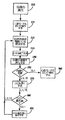
図10は、伝導性検査を実行するための過程を示す流れ図である。上記のような心室ペーシングプロトコルに従って心房ペーシングモードにおいて動作しているとき、患者は内因性伝導を喪失している(200)。任意の所与のプロトコルが、それを果たすのに数周期かかることがあるとき、しばらくすると、そのデバイスは一般的には、二腔ペーシングモード(たとえば、DDD/R)において動作する(210)。IMD10は、伝導性検査間隔(CCI)を開始する(220)。これはタイマ、ペーシング周期のカウント、又はデバイスが伝導性検査を試みるべきときを指示するために用いられる類似の仕組みである。CCIの満了時に(230)、IMD10は伝導性検査を実行し(240)、内因性伝導(250)があるか否かを判定する。内因性伝導がある場合には、IMD10は、心房ペーシングモードにおいて動作する(260)。
FIG. 10 is a flowchart illustrating a process for performing a conductivity test. When operating in atrial pacing mode according to a ventricular pacing protocol as described above, the patient has lost intrinsic conduction (200). When any given protocol may take several cycles to fulfill, after a while, the device typically operates in a dual chamber pacing mode (eg, DDD / R) (210). The
内因性伝導が見つからない場合には(250)、或る所定の量だけCCIを増加させる(270)。CCIが評価され(280)、最大値以下である場合には、その過程はCCIの開始(220)に戻る。これは、CCIの最大値にあるか、又はCCIの増加した値にある(270)かのいずれかであろう。このようにして、最大値に達するまで、CCIを徐々に増加させる。すなわち、CCIが最大値よりも大きい場合には(280)、CCIは最大値に変更され、その過程は(220)に戻る。プログラムされたパターンによって、任意の所与の増加量が求められる。上記で示されたように、これは、一実施形態では、1分、2分、4分、8分、16分及び32分、その後、1時間、2時間、4時間、8時間及び16時間にすることができ、16時間が最大値である。このように進めることは単なる例示であり、それよりも多くの、又は少ない反復が利用されることがあり、それに応じて、値が選択されることがあることは理解されたい。さらに、ステップ(280)は、カウンタを組み込んで、その値を増加させる前に、所与の値において何度も試行が行われることがあるように変更することができる。
If endogenous conduction is not found (250), the CCI is increased by some predetermined amount (270). If the CCI is evaluated (280) and below the maximum value, the process returns to the start of the CCI (220). This will either be at the maximum value of CCI or at an increased value of CCI (270). In this way, the CCI is gradually increased until the maximum value is reached. That is, when the CCI is larger than the maximum value (280), the CCI is changed to the maximum value, and the process returns to (220). Any given increment is determined by the programmed pattern. As indicated above, this is in one
図11は、周期的に行われる伝導性検査を示す概略的なタイミング図である。バー300及び320はいずれも時間を示し、具体的には12時間間隔が示されている。矢印310は、最大値において行われる伝導性検査のパターンを示す。パターン「a」では、伝導性検査が16時間毎に行われている。時間バー320及び時間帯指標330を参照すると、最初の伝導性検査が16時に行われ、それが午後であることが容易に明らかになる。次の伝導性検査は8時に行われることになり、それは午前であり、次の伝導性検査は24時(真夜中)に行われ、夜間の評価を表す。16時間間隔が保持される場合には、このパターンが繰り返されることになり、概日性の区別が達成される。伝導の喪失は開始事象であり、最終的に用いられる実際の時間帯は、トリガ事象から得られることは理解されたい。
FIG. 11 is a schematic timing diagram showing a periodic conductivity test. Both
個別に図示されないが、この変形形態は、さらに概日可変性を達成するためにわずかに変更されることがある。上記で示されたように、16時間間隔の場合、午後、午前及び夜間の進行が繰り返されることになり、伝導性検査は概ね同じ時刻に行われる(たとえば、16時、8時、24時)。この1組の伝導性検査は、完全な概日サブセットとして分類することができる。すなわち、日常の3つの主な時間中にそれぞれ、少なくとも1回の検査が行われる。1つの概日サブセット(又は或る所定の数のサブセット)後に、オフセット値を導入することができる。オフセットのために選択される値は重要ではない。1時間、2時間又は3時間が一般的であるが、任意の値(正又は負)を許容できる。こうして、概日サブセット(所定の概日サブセット数の、最後のサブセット)が終了した後に、もう一度繰り返すために、CCI値にオフセット値が加えられる。したがって、この例では、CCI最大時間は16時間であり、1つの概日サブセット後に、1時間のオフセット値が加えられて、次の伝導性検査が、16時間後ではなく、17時間後に行われるようにする。しかしながら、オフセット値は保持されず、後続の伝導性検査は16時間後に起こる。したがって、例示的なパターンは16−16−16−17−16−16等になるであろう。別の言い方をすると、伝導性検査は、16時、8時、24時、17時、9時等において行うことができる。このようにして、概日区別が後続の各伝導性検査間で常に保持され、所定期間にわたって、毎日の時間の中でそれぞれ、さらに変化が与えられる。 Although not individually illustrated, this variation may be slightly modified to further achieve circadian variability. As indicated above, in the case of a 16 hour interval, the afternoon, morning and night progression will be repeated and the conductivity test will be performed at approximately the same time (eg, 16:00, 8 o'clock, 24 o'clock). . This set of conductivity tests can be classified as a complete circadian subset. That is, at least one test is performed during each of the three main times of day. The offset value can be introduced after one circadian subset (or some predetermined number of subsets). The value chosen for the offset is not important. One hour, two hours, or three hours are common, but any value (positive or negative) is acceptable. Thus, an offset value is added to the CCI value to repeat once after the circadian subset (the last subset of a given number of circadian subsets) is finished. Thus, in this example, the CCI maximum time is 16 hours, and after one circadian subset, an offset value of 1 hour is added and the next conductivity test is done after 17 hours instead of after 16 hours. Like that. However, the offset value is not retained and subsequent conductivity testing occurs after 16 hours. Thus, an exemplary pattern would be 16-16-16-17-16-16, etc. In other words, the conductivity test can be performed at 16:00, 8 o'clock, 24 o'clock, 17 o'clock, 9 o'clock, or the like. In this way, circadian distinction is always maintained between each subsequent conductivity test, and further changes are given in the daily time over a predetermined period of time.
フィードバック機構を用いることができ、成功した伝導性検査が注目され、オフセット値を用いて、過去において成功したことがわかっている時間中に伝導性検査が行われるようにすることができる。言い換えると、IMD10は、伝導性検査に成功する可能性を高める患者特有のパラメータを学習することができ、それに応じて、その進行を調整することができる。
A feedback mechanism can be used, and a successful conductivity test is noted, and an offset value can be used to cause the conductivity test to be performed during a time known to have been successful in the past. In other words, the
図11に戻ると、パターン「b」は、32時間間隔において行われる伝導性検査を示す。これは概日可変性を保持するが、間隔が長くなるので、後続の伝導性検査間で、さらに長い時間が経過し、任意の所与の時間帯における反復検査間でもさらに長い時間が経過する。パターン「c」は、所定の時間として16時間間隔を用いるが、成功しない場合には、32時間まで最大値を増加させることを表す。その数は限定するものではないが、概念的には、長期にわたって伝導性検査が失敗し続ける場合には、成功の可能性が小さくなり、伝導性検査の頻度を下げることを正当化することができる。パターン「d」は、20時間間隔で行われる伝導性検査を示す。したがって、所望の時間的な関係を達成するために、種々のパターンが用いられることがあることは明らかである。 Returning to FIG. 11, pattern “b” shows a conductivity test performed at 32 hour intervals. This retains circadian variability, but due to the longer interval, longer time passes between subsequent conductivity tests and even longer between repeated tests at any given time period. . The pattern “c” indicates that a 16-hour interval is used as the predetermined time, but if it is not successful, the maximum value is increased to 32 hours. The number is not limited, but conceptually, if the conductivity test continues to fail over time, the likelihood of success will be lessened and it may justify reducing the frequency of the conductivity test. it can. The pattern “d” indicates a conductivity test performed at 20 hour intervals. Thus, it is clear that various patterns may be used to achieve the desired temporal relationship.
一実施形態では、完全なAV伝導を探索し、ADI/Rを回復するために用いられるアルゴリズムは、2つのオプションのうちの1つに従って定義される。第1のオプションは、DDD/R動作中に心室ペース刺激を単に控えることである。心室ペーシングが控えられた生理的心房事象に続いて、心室検知が生じる場合には、ADI/Rペーシングが再開される。そうでない場合には、DDD/Rペーシングが継続し、その後、予定どおりに再試行されるか、又は手動で起動することによって再試行される(上記で詳述されている)。完全なAV伝導の第2のオプションの探索は、DDD/Rペーシング中のAV遅延を、予め指定されたAV伝導(探索)間隔(AVCI)まで延長することを伴う。たとえば、AVCIが400msである場合、生理的心房事象(検知又はペーシング)後に、AV遅延が400msまで延長される。AV間隔が心室検知によって中断され、それにより、DDD/R動作において心室ペースを回避する場合には、モードスーパーバイザはADI/R動作に戻る。そうでない場合には、AVCI間隔の満了時に、心室ペースが送出され、DDD/R動作が再開し、上記のように予定どおりに(又は手動による起動で)再試行される。 In one embodiment, the algorithm used to search for complete AV conduction and recover ADI / R is defined according to one of two options. The first option is to simply refrain from ventricular pace stimulation during DDD / R operation. If ventricular sensing occurs following a physiologic atrial event in which ventricular pacing was refrained, ADI / R pacing is resumed. Otherwise, DDD / R pacing continues and is then retried as scheduled or retried by manually triggering (detailed above). The search for a second option for full AV conduction involves extending the AV delay during DDD / R pacing to a pre-specified AV conduction (search) interval (AVCI). For example, if the AVCI is 400 ms, after a physiological atrial event (sensing or pacing), the AV delay is extended to 400 ms. If the AV interval is interrupted by ventricular sensing, thereby avoiding ventricular pace in DDD / R operation, the mode supervisor returns to ADI / R operation. Otherwise, at the expiration of the AVCI interval, the ventricular pace is delivered and DDD / R operation resumes and is retried as scheduled (or with manual activation) as described above.
モードスーパーバイザは、一実施形態において最大試験持続期間で、繰返し失敗したAV伝導試験をモニタする。したがって、たとえば、16時間間隔で、AV伝導の試験が7回立て続けに失敗する場合には、モードスーパーバイザは、AV伝導試験を一時中止することができ、その際、デバイスは無期限にDDD/Rモードに留まることができる。代替的に、本発明は、最大間隔において、伝導性検査を実行し続けることができる。これにより、プログラミングオプションを簡単にできるようになる。すなわち、完全心ブロックが生じる場合であっても、そのプロトコルは、患者にとって都合よく機能し、起こりそうもない場合であっても、内因性伝導の戻りを確認することができる。 The mode supervisor monitors repeatedly failed AV conduction tests in one embodiment with a maximum test duration. Thus, for example, at 16-hour intervals, if the AV conduction test fails 7 times in succession, the mode supervisor can suspend the AV conduction test, in which case the device will DDD / R indefinitely. Can stay in mode. Alternatively, the present invention can continue to conduct conductivity tests at maximum intervals. This simplifies programming options. That is, even when a complete heart block occurs, the protocol works well for the patient and can confirm the return of intrinsic conduction even when it is unlikely.
上記で示されたように、AVCIは、名目値(たとえば、150ms)から、或る所定の値、たとえば、上記で述べられた400msまで延長されることがある。名目値は、DDDモード又はDDDRモードのようなモードにおける標準的な動作のために用いられる、従来どおりにプログラムされたパラメータを示すことを意図している。通常、名目値は約150ms〜180msの範囲内にある。延長されたAV間隔は、より長い窓を提供し、その最中に、内因性伝導が戻ることがあり、それにより心房ペーシングモードに戻ることができるようになる。デバイスが二腔ペーシングモードに留まるとき、必要に応じて、その間隔の終わりに心室ペーシングが提供される。 As indicated above, AVCI may be extended from a nominal value (eg, 150 ms) to some predetermined value, eg, 400 ms as described above. The nominal value is intended to indicate a conventionally programmed parameter used for standard operation in a mode such as DDD mode or DDDR mode. Usually, the nominal value is in the range of about 150 ms to 180 ms. The extended AV interval provides a longer window during which intrinsic conduction may return, thereby returning to the atrial pacing mode. When the device remains in the dual chamber pacing mode, ventricular pacing is provided at the end of the interval, if necessary.
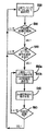
図12は、この全過程を示す流れ図である。例示するために、デバイスは、心房モードにあるものと仮定される(500)。上記で説明されたように、デバイスは内因性伝導をモニタする。存在する場合には(510)、デバイスは心房モードに留まる(500)。内因性伝導が失敗する場合には(510)、デバイスは、二腔ペーシングモードへの変更が必要とされるか否かを判定する(520)。必要とされない場合には、デバイスは再び、心房ペーシングモードに留まる(500)。 FIG. 12 is a flowchart showing the entire process. To illustrate, the device is assumed to be in atrial mode (500). As explained above, the device monitors intrinsic conduction. If present (510), the device remains in atrial mode (500). If the intrinsic conduction fails (510), the device determines whether a change to dual chamber pacing mode is required (520). If not needed, the device again remains in the atrial pacing mode (500).
適切な場合には、そのデバイスは、適切に求められるAV間隔(530b)において、二腔ペーシングモードにおいて動作するであろう(530a)。周期的に伝導性検査が実行され(540)、結果として(550)、デバイスが二腔ペーシングモードにおいて動作するか、又は心房ペーシングモードにおいて動作するかが判定される。 If appropriate, the device will operate (530a) in a dual chamber pacing mode with an appropriately determined AV interval (530b). Periodic conductivity tests are performed (540) and as a result (550) it is determined whether the device operates in a dual chamber pacing mode or an atrial pacing mode.
図13は、二腔ペーシングモードにおいて動作している間に、AV間隔を求めるための種々のオプションを示す。取り扱われる3つの包括的なカテゴリが存在する。第1のカテゴリは、二腔ペーシングモードにおいて動作する初期周期又は最初の数周期の間である(560)。第2のカテゴリ(600)は、最大CCI未満において行われている、周期的又は漸進的な伝導性検査の時間中である。第3のカテゴリは、CCIが最大値である間(680)、代替的に伝導性検査が終了されたときの、二腔ペーシングモードにおける動作である。 FIG. 13 shows various options for determining the AV interval while operating in the dual chamber pacing mode. There are three comprehensive categories that are addressed. The first category is during the initial period or the first few periods operating in the dual chamber pacing mode (560). The second category (600) is during the period of periodic or gradual conductivity testing taking place below the maximum CCI. The third category is operation in the dual chamber pacing mode when the conductivity test is alternatively terminated while the CCI is at its maximum value (680).
第1のカテゴリ(560)では、動作は、心室脱分極が欠如した直後の1周期又は数周期を含むことがある。したがって、一実施形態では、二腔モードにおけるこの最初の周期では、AV間隔は、名目値よりも短くなることがある(570)。たとえば、短縮されたAV間隔は80msに設定されることがある。代替的に、AV間隔は、プログラムし直された名目値に設定されることがある(580)。他の実施形態では、この最初の周期は、AVCIのような、延長された(たとえば、名目値よりも長い)AV間隔を含むことがある。選択されたVPPは、このモードにおける最初の周期、及び/又は最初の数周期のために適した二腔ペーシングプロトコルを判定することになり、このカテゴリを分けることは、AV間隔を設定することに関する以下のオプションが、このカテゴリ(560)においてオプションで適用されることがあることを例示することを単に意図している。 In the first category (560), the action may include one or several cycles immediately following the lack of ventricular depolarization. Thus, in one embodiment, the AV interval may be shorter than the nominal value (570) during this initial cycle in dual chamber mode. For example, the shortened AV interval may be set to 80 ms. Alternatively, the AV interval may be set to a reprogrammed nominal value (580). In other embodiments, this initial period may include an extended AV interval (eg, longer than the nominal value), such as AVCI. The selected VPP will determine the appropriate two-chamber pacing protocol for the first period and / or the first few periods in this mode, and dividing this category is related to setting the AV interval. It is merely intended to illustrate that the following options may be optionally applied in this category (560).
第2のカテゴリ(600)は、伝導性検査が実行されている間の二腔ペーシングモードにおける動作を参照する。上記で説明されたように、そのような伝導性検査間の間隔、たとえば、CCIは異なることがあり、一般的には、連続して試行が成功しないと、最大間隔に達するまで長くなる。このカテゴリでは、AV間隔は名目値(610)に設定されることがある。もちろん、名目的なAV間隔中に、内因性事象が生じることもあり得るであろう。しかしながら、このオプションによれば、VPPは主に伝導性検査そのものに基づいて、内因性伝導が戻っているか否かを判定している。 The second category (600) refers to operation in a dual chamber pacing mode while a conductivity test is being performed. As explained above, the interval between such conductivity tests, e.g., CCI, can be different and generally increases until the maximum interval is reached if consecutive trials are not successful. In this category, the AV interval may be set to a nominal value (610). Of course, endogenous events could occur during the nominal AV interval. However, according to this option, the VPP determines whether intrinsic conduction has returned, mainly based on the conductivity test itself.
別の実施形態では、AV間隔は、或る最大安全延長値、又は名目的なAV間隔よりも長い少なくとも1つの固定値(たとえば、AVCI)に設定される(620)。したがって、心周期毎に、二腔ペーシングモードにおいて心室ペーシング能力を依然として提供しながら、内因性伝導が戻るための機会が、最大ではないにしても増える。 In another embodiment, the AV interval is set 620 to some maximum safe extension value or at least one fixed value (eg, AVCI) that is longer than the nominal AV interval. Thus, every cardiac cycle increases, if not the maximum, the opportunity for intrinsic conduction to return while still providing ventricular pacing capability in a dual chamber pacing mode.
別の実施形態では、伝導性検査が進行するのに応じて、AV間隔が調節される(630)。一般的に、これは、AV間隔が最初に長くなり(第1のカテゴリ(560)中にいかなる変化も生じない)、伝導性検査が進行し、連続して失敗するのに応じて短くされることを意味する。AV間隔の変化又は調節は、CCIの変化に関連し得る。 In another embodiment, the AV interval is adjusted (630) as the conductivity test progresses. In general, this will be shortened as the AV interval first increases (no change occurs during the first category (560)) and the conductivity test proceeds and fails continuously. Means. Changes or regulation of the AV interval can be related to changes in CCI.
一実施形態では、AV間隔は、第2のカテゴリ(600)中の伝導性検査過程にわたって、所定の割合で次第に短くなるであろう(640)。代替的に、AV間隔は、CCIが変化する度にステップ関数として減少することがある(650)。次第に短くなること、又はステップ関数は、所定の時間間隔に基づくことがあるか、又はパーセンテージを基にする変化に基づくことがある。同様に、AV間隔は、CCIに反比例するように調整されることがある(660)。 In one embodiment, the AV interval will gradually decrease (640) at a predetermined rate over the conductivity testing process in the second category (600). Alternatively, the AV interval may decrease as a step function each time the CCI changes (650). The gradual shortening or the step function may be based on a predetermined time interval or may be based on a percentage based change. Similarly, the AV interval may be adjusted to be inversely proportional to CCI (660).
一般的に、上記の変化は、連続して成功しなかった伝導性検査に直に適用される。伝導性検査が間欠的に成功する場合には、心周期又は一連の心周期が成功する度に、VPPは、この過程を再開する。これは完全に許容することができる。しかしながら、これらの間欠的な事象が生じる場合には、所望により、AV間隔は、名目値に近い値又は等しい値に設定されることがあり、次第に短くする割合を増やすことができ、ステップ毎の変化を大きくすることができ、比例(反比例)の割合を増やして、名目的なAV間隔にさらに迅速に導くことができる。 In general, the above changes apply directly to conductivity tests that have not succeeded in succession. If the conductivity test is intermittently successful, the VPP resumes this process every time a cardiac cycle or series of cardiac cycles succeeds. This can be completely tolerated. However, if these intermittent events occur, the AV interval may be set to a value close to or equal to the nominal value as desired, and the rate of reduction can be gradually increased. The change can be increased and the proportion (inverse proportion) can be increased to lead more quickly to the nominal AV interval.
一実施形態では、心房ペーシングモードにおいて費やされる時間のパーセンテージが、二腔ペーシングモードにおいて費やされる時間のパーセンテージと比較される。二腔ペーシングモードにおいて費やされる時間のパーセンテージが所定のしきい値を超える場合には、上記の動作のうちのいずれかを行って、AV間隔を、より迅速に減少させるか、又は名目値に設定する。代替的に、デバイスがAV間隔を変更するための仕組みは、所与の数の心周期にわたるモード切替の回数、又は所定の時間枠内のモード切替の回数を含むことがある。 In one embodiment, the percentage of time spent in the atrial pacing mode is compared to the percentage of time spent in the dual chamber pacing mode. If the percentage of time spent in the dual chamber pacing mode exceeds a predetermined threshold, perform one of the above actions to decrease the AV interval more quickly or set to a nominal value To do. Alternatively, the mechanism for the device to change the AV interval may include the number of mode switches over a given number of cardiac cycles, or the number of mode switches within a predetermined time frame.
一実施形態では、AV間隔は、成功しない伝導性検査が生じるのに応じて、徐々に低減される。或る時点において、CCIは最大値に達することがある(680)。上記で説明されたように、この最大CCIにおいて(変化の有無にかかわらず)、伝導性検査が終わることがあるか、または行われることがある。いずれにしても、AV間隔は名目値に設定される(690)。最大CCIにおいて行われることがある伝導性検査に加えて、内因性伝導が戻るのを容易にするために、この伝導性検査の前に数周期にわたって、AV間隔が延長されることがある。AV間隔の周期的な延長は、予め決められたように実行することができる代替の伝導性検査機能としての役割を果たすこともできる。 In one embodiment, the AV interval is gradually reduced as unsuccessful conductivity tests occur. At some point, the CCI may reach a maximum value (680). As explained above, at this maximum CCI (regardless of whether there is a change), the conductivity test may or may not be completed. In any case, the AV interval is set to a nominal value (690). In addition to the conductivity test that may be performed at maximum CCI, the AV interval may be extended for several cycles prior to this conductivity test to facilitate the return of intrinsic conduction. Periodic extension of the AV interval can also serve as an alternative conductivity test function that can be performed as predetermined.
そのデバイスは実際には二腔動作にあり、名目的なAV間隔は従来の一般に認められているペーシングプログラミングパラメータに従って設定されるので、CCIが最大値にあるときに、AV間隔は名目値に設定される。代替的に、CCIが最大値にある場合であっても、AV間隔が、連続的に又は間欠的に調節されることがある(700)。これは、患者を、最大値に設定されたAV間隔下に連続して置くことなく、心室ペーシングを保持しながら、定期的に実行されることがある伝導性検査の変形形態としての役割も果たすであろう。 The device is actually in dual chamber operation, and the nominal AV interval is set according to conventional accepted pacing programming parameters, so when the CCI is at the maximum value, the AV interval is set to the nominal value. Is done. Alternatively, the AV interval may be adjusted continuously or intermittently even when the CCI is at a maximum (700). This also serves as a variant of a conductivity test that may be performed periodically while maintaining ventricular pacing without continuously placing the patient under the AV interval set to the maximum value. Will.
本発明は、医療デバイスによってセーブされる(又は、医療デバイスにダウンロードされる)実行可能ソフトウエアコード及び/又は動作パラメータを用いて実施することができる。そのようなデバイスは、体内に配置され、本発明に従って後にプログラムされることもできるし、又は埋め込む前にプログラムされることもできる(たとえば、遠隔測定技法等を用いてプログラムし直されることがあるか、又は変更されることがあるファームウエアを用いる)。しかしながら、本発明は、ファームウエア又はハードウエアの実施態様だけには限定されない。実際には、本発明は、当該技術分野において知られており、用いられているデバイスプログラミング技法を用いて、所望のように混成形態で、又は組み合わせて実施することができる。 The present invention may be implemented using executable software code and / or operating parameters that are saved by (or downloaded to) a medical device. Such devices may be placed in the body and later programmed according to the present invention or programmed prior to implantation (eg, may be reprogrammed using telemetry techniques, etc.). Or firmware that is subject to change). However, the present invention is not limited to just firmware or hardware implementations. In practice, the present invention is known in the art and can be implemented in a hybrid form or combination as desired using the device programming techniques used.
上記の説明が例示することを意図しており、限定することを意図していないことは理解されたい。上記の説明を読み、理解すると、当業者には数多くの他の実施形態が明らかになるであろう。それゆえ、本発明の範囲は、添付の特許請求の範囲が権利を与えられる均等物の全範囲とともに、添付の特許請求の範囲を参照することによって決定されるべきである。 It should be understood that the above description is intended to be illustrative and not limiting. Many other embodiments will be apparent to those of skill in the art upon reading and understanding the above description. The scope of the invention should, therefore, be determined by reference to the appended claims, along with the full scope of equivalents to which such claims are entitled.
Claims (7)
前記埋め込み可能医療デバイスを制御すると共に心房ペーシングモード又は二腔ペーシングモードにおいて前記埋め込み可能医療デバイスを選択的に動作させるための心室ペーシングプロトコルモジュールを含む処理ユニットであって、当該心室ペーシングプロトコルモジュールが、IMDを、心房ベースのペーシングモード又は二腔ベースのペーシングモードで、選択的に動作させることを含む心室ペーシングプロトコル(VPP)に従って作動し、VPPが、内因性AV伝導を検知する際に心房ベースのペーシングモードを利用するペーシングプロトコルであり、ペーシングモードが、2つの連続的な心房ペーシングパルスの間で、心室活動無しに、完全な心周期が経過することを許容し、心室活動無しに経過することが許容された心周期の直後の心周期で心室ペーシングパルスを送出するものと、
前記処理ユニットの制御下で心臓ペーシングを選択的に提供するためのパルス発生器と、
前記処理ユニットと通信可能に接続され、前記二腔ペーシングモードにおいて動作するときに前記処理ユニットに伝導性検査を実行させるための内因性伝導性検査モジュールであって、該伝導性検査は所定のパターンに従って行われる、内因性伝導性検査モジュールと、
前記二腔ペーシングモードにおいて動作するときに、前記所定のパターンに基づいて、AV間隔の持続期間を変更するためのAV間隔モジュールと
を備える、埋め込み可能医療デバイス(IMD)。An implantable medical device (IMD),
A processing unit including a ventricular pacing protocol module for controlling the implantable medical device and selectively operating the implantable medical device in an atrial pacing mode or a dual chamber pacing mode, the ventricular pacing protocol module comprising : The IMD operates according to a ventricular pacing protocol (VPP) that includes selectively operating in an atrial-based pacing mode or a dual chamber-based pacing mode, and the VPP detects an atrial-based pacing when detecting intrinsic AV conduction. A pacing protocol that utilizes a pacing mode that allows a complete cardiac cycle to elapse between two consecutive atrial pacing pulses without ventricular activity and without ventricular activity. Peripheral circumference To those delivering ventricular pacing pulses in the cardiac cycle immediately following,
A pulse generator for selectively providing cardiac pacing under the control of the processing unit;
An intrinsic conductivity test module that is communicatively connected to the processing unit and causes the processing unit to perform a conductivity test when operating in the dual chamber pacing mode, wherein the conductivity test has a predetermined pattern An intrinsic conductivity test module,
An implantable medical device (IMD) comprising an AV interval module for changing a duration of an AV interval based on the predetermined pattern when operating in the dual chamber pacing mode.
Applications Claiming Priority (3)
| Application Number | Priority Date | Filing Date | Title |
|---|---|---|---|
| US11/115,605 US7738955B2 (en) | 2000-12-21 | 2005-04-27 | System and method for ventricular pacing with AV interval modulation |
| US11/115,605 | 2005-04-27 | ||
| PCT/US2006/014094 WO2006115836A1 (en) | 2005-04-27 | 2006-04-14 | System and method for ventricular pacing with av interval modulation |
Publications (3)
| Publication Number | Publication Date |
|---|---|
| JP2008538993A JP2008538993A (en) | 2008-11-13 |
| JP2008538993A5 JP2008538993A5 (en) | 2009-05-14 |
| JP5118630B2 true JP5118630B2 (en) | 2013-01-16 |
Family
ID=36763974
Family Applications (1)
| Application Number | Title | Priority Date | Filing Date |
|---|---|---|---|
| JP2008508904A Active JP5118630B2 (en) | 2005-04-27 | 2006-04-14 | System for ventricular pacing to adjust AV interval |
Country Status (5)
| Country | Link |
|---|---|
| US (1) | US7738955B2 (en) |
| EP (1) | EP1901801B1 (en) |
| JP (1) | JP5118630B2 (en) |
| CA (1) | CA2605620A1 (en) |
| WO (1) | WO2006115836A1 (en) |
Families Citing this family (24)
| Publication number | Priority date | Publication date | Assignee | Title |
|---|---|---|---|---|
| US7738955B2 (en) | 2000-12-21 | 2010-06-15 | Medtronic, Inc. | System and method for ventricular pacing with AV interval modulation |
| US7245966B2 (en) | 2000-12-21 | 2007-07-17 | Medtronic, Inc. | Ventricular event filtering for an implantable medical device |
| US9931509B2 (en) | 2000-12-21 | 2018-04-03 | Medtronic, Inc. | Fully inhibited dual chamber pacing mode |
| US7248924B2 (en) | 2004-10-25 | 2007-07-24 | Medtronic, Inc. | Self limited rate response |
| US7283872B2 (en) * | 2005-01-21 | 2007-10-16 | Medtronic, Inc. | Implantable medical device with ventricular pacing protocol |
| US7925344B2 (en) | 2006-01-20 | 2011-04-12 | Medtronic, Inc. | System and method of using AV conduction timing |
| US8046063B2 (en) * | 2006-02-28 | 2011-10-25 | Medtronic, Inc. | Implantable medical device with adaptive operation |
| US7848808B2 (en) * | 2006-02-28 | 2010-12-07 | Medtronic, Inc. | System and method for delivery of cardiac pacing in a medical device in response to ischemia |
| US7894898B2 (en) | 2006-06-15 | 2011-02-22 | Medtronic, Inc. | System and method for ventricular interval smoothing following a premature ventricular contraction |
| US7565196B2 (en) * | 2006-06-15 | 2009-07-21 | Medtronic, Inc. | System and method for promoting intrinsic conduction through atrial timing |
| US7783350B2 (en) * | 2006-06-15 | 2010-08-24 | Medtronic, Inc. | System and method for promoting intrinsic conduction through atrial timing modification and calculation of timing parameters |
| US7869872B2 (en) | 2006-06-15 | 2011-01-11 | Medtronic, Inc. | System and method for determining intrinsic AV interval timing |
| US7689281B2 (en) | 2006-07-31 | 2010-03-30 | Medtronic, Inc. | Pacing mode event classification with increased ventricular sensing |
| US7856269B2 (en) | 2006-07-31 | 2010-12-21 | Medtronic, Inc. | System and method for determining phsyiologic events during pacing mode operation |
| US7515958B2 (en) | 2006-07-31 | 2009-04-07 | Medtronic, Inc. | System and method for altering pacing modality |
| US7502647B2 (en) | 2006-07-31 | 2009-03-10 | Medtronic, Inc. | Rate smoothing pacing modality with increased ventricular sensing |
| EP2069007B8 (en) | 2006-07-31 | 2012-04-11 | Medtronic, Inc. | System for determining physiological events during pacing mode operation |
| US7715914B2 (en) | 2006-07-31 | 2010-05-11 | Medtronic, Inc. | System and method for improving ventricular sensing |
| US7720537B2 (en) | 2006-07-31 | 2010-05-18 | Medtronic, Inc. | System and method for providing improved atrial pacing based on physiological need |
| WO2009075749A1 (en) * | 2007-12-11 | 2009-06-18 | Cardiac Pacemakers, Inc. | Lv unipolar sensing or pacing vector |
| DE102008042681A1 (en) * | 2008-10-08 | 2010-04-15 | Biotronik Crm Patent Ag | Method and device for processing cardiac signals |
| EP2403593B1 (en) | 2009-02-27 | 2014-04-09 | Medtronic, Inc | System for conditional biventricular pacing |
| WO2010099424A1 (en) | 2009-02-27 | 2010-09-02 | Medtronic, Inc. | A system and method for conditional biventricular pacing |
| US8244354B2 (en) | 2009-02-27 | 2012-08-14 | Medtronic, Inc. | System and method for conditional biventricular pacing |
Family Cites Families (99)
| Publication number | Priority date | Publication date | Assignee | Title |
|---|---|---|---|---|
| US3057356A (en) * | 1960-07-22 | 1962-10-09 | Wilson Greatbatch Inc | Medical cardiac pacemaker |
| US3253596A (en) * | 1963-05-27 | 1966-05-31 | Cordis Corp | Cardiac pacer |
| US3478746A (en) * | 1965-05-12 | 1969-11-18 | Medtronic Inc | Cardiac implantable demand pacemaker |
| US3595242A (en) * | 1969-03-26 | 1971-07-27 | American Optical Corp | Atrial and ventricular demand pacer |
| US3648707A (en) * | 1969-07-16 | 1972-03-14 | Medtronic Inc | Multimode cardiac paces with p-wave and r-wave sensing means |
| US3747604A (en) * | 1969-12-15 | 1973-07-24 | American Optical Corp | Atrial and ventricular demand pacer with separate atrial and ventricular beat detectors |
| US4312355A (en) * | 1977-01-12 | 1982-01-26 | Medtronic B.V. | Heart pacemaker |
| US4476868A (en) * | 1978-11-06 | 1984-10-16 | Medtronic, Inc. | Body stimulator output circuit |
| US4432362A (en) | 1980-05-27 | 1984-02-21 | Cordis Corporation | Atrial-based, atrial-ventricular sequential cardiac pacer |
| US4386610A (en) * | 1980-05-27 | 1983-06-07 | Cordis Corporation | Ventricular-inhibited cardiac pacer |
| US4432632A (en) * | 1981-01-13 | 1984-02-21 | Ricoh Company, Ltd. | Apparatus for holding a recording member in the form of an endless belt in a recording system using the same |
| US4428378A (en) * | 1981-11-19 | 1984-01-31 | Medtronic, Inc. | Rate adaptive pacer |
| US4523593A (en) * | 1983-06-15 | 1985-06-18 | Medtronic, Inc. | Constant A-A interval control for DVI and DDD cardiac pacemakers |
| US4726380A (en) | 1983-10-17 | 1988-02-23 | Telectronics, N.V. | Implantable cardiac pacer with discontinuous microprocessor, programmable antitachycardia mechanisms and patient data telemetry |
| US4577633A (en) * | 1984-03-28 | 1986-03-25 | Medtronic, Inc. | Rate scanning demand pacemaker and method for treatment of tachycardia |
| US4727877A (en) * | 1984-12-18 | 1988-03-01 | Medtronic, Inc. | Method and apparatus for low energy endocardial defibrillation |
| US4587970A (en) * | 1985-01-22 | 1986-05-13 | Telectronics N.V. | Tachycardia reversion pacer |
| CA1290813C (en) * | 1985-08-12 | 1991-10-15 | Michael B. Sweeney | Pacemaker for detecting and terminating a tachycardia |
| US4953551A (en) * | 1987-01-14 | 1990-09-04 | Medtronic, Inc. | Method of defibrillating a heart |
| US4856523A (en) * | 1987-10-08 | 1989-08-15 | Siemens-Pacesetter, Inc. | Rate-responsive pacemaker with automatic mode switching and/or variable hysteresis rate |
| US4890617A (en) * | 1987-11-25 | 1990-01-02 | Medtronic, Inc. | Dual chamber activity responsive pacer |
| US4856524A (en) * | 1988-08-29 | 1989-08-15 | Intermedics, Inc. | A-V responsive rate adaptive pacemaker |
| US4941471A (en) * | 1988-09-07 | 1990-07-17 | Medtronic, Inc. | Rate stabilization pacemaker |
| US4932046A (en) * | 1989-07-28 | 1990-06-05 | First Data Resources Inc. | Telephone programming system for automated calling |
| US5052388A (en) * | 1989-12-22 | 1991-10-01 | Medtronic, Inc. | Method and apparatus for implementing activity sensing in a pulse generator |
| US5097832A (en) * | 1990-03-09 | 1992-03-24 | Siemens-Pacesetter, Inc. | System and method for preventing false pacemaker pvc response |
| US5085215A (en) * | 1990-03-20 | 1992-02-04 | Telectronics Pacing Systems, Inc. | Metabolic demand driven rate-responsive pacemaker |
| US5144950A (en) * | 1990-08-30 | 1992-09-08 | Vitatron Medical B.V. | Rate controlled pacemaker system using ar interval for rate control |
| US5163427A (en) * | 1990-11-14 | 1992-11-17 | Medtronic, Inc. | Apparatus for delivering single and multiple cardioversion and defibrillation pulses |
| US5188105A (en) * | 1990-11-14 | 1993-02-23 | Medtronic, Inc. | Apparatus and method for treating a tachyarrhythmia |
| US5117824A (en) * | 1990-11-14 | 1992-06-02 | Medtronic, Inc. | Apparatus for monitoring electrical physiologic signals |
| US5318594A (en) * | 1990-11-30 | 1994-06-07 | Ela Medical | DDD type cardiac pacemaker having automatic operating mode switching |
| US5133350A (en) * | 1991-01-31 | 1992-07-28 | Medtronic, Inc. | Mode switching pacemaker |
| US5228438A (en) * | 1991-10-08 | 1993-07-20 | Siemens Pacesetter, Inc. | Implantable pacemaker including means and method of terminating a pacemaker-mediated tachycardia during rate adaptive pacing |
| US5188117A (en) * | 1991-10-25 | 1993-02-23 | Telectronics Pacing Systems, Inc. | Notch filter noise rejection system in a cardiac control device |
| US5273035A (en) * | 1992-02-03 | 1993-12-28 | Medtronic, Inc. | Dual chamber pacemaker with safe airial pacing |
| US5417714A (en) * | 1992-03-05 | 1995-05-23 | Pacesetter, Inc. | DDI pacing with PVC-protected hysteresis and automatic AV interval adjustment |
| US5334222A (en) * | 1992-11-03 | 1994-08-02 | Cardiac Pacemakers, Inc. | Cardiac stimulating apparatus and method for heart failure therapy |
| US5741308A (en) * | 1992-11-13 | 1998-04-21 | Pacesetter, Inc. | Dual-chamber implantable pacemaker and method of operating same for automatically setting the pacemaker's AV interval as a function of a natural measured conduction time |
| US5814077A (en) * | 1992-11-13 | 1998-09-29 | Pacesetter, Inc. | Pacemaker and method of operating same that provides functional atrial cardiac pacing with ventricular support |
| US5334220A (en) * | 1992-11-13 | 1994-08-02 | Siemens Pacesetter, Inc. | Dual-chamber implantable pacemaker having an adaptive AV interval that prevents ventricular fusion beats and method of operating same |
| FR2699413B1 (en) * | 1992-12-23 | 1995-02-24 | Ela Medical Sa | Implantable pacemaker. |
| US5292340A (en) * | 1993-01-04 | 1994-03-08 | Telectronics Pacing Systems, Inc. | Physiologically-calibrated rate adaptive, dual chamber pacemaker |
| US5345362A (en) * | 1993-04-29 | 1994-09-06 | Medtronic, Inc. | Portable computer apparatus with articulating display panel |
| US5372607A (en) * | 1993-06-23 | 1994-12-13 | Medtronic, Inc. | Method and apparatus for monitoring pacemaker intervals |
| US5522859A (en) * | 1993-09-29 | 1996-06-04 | Medtronic, Inc. | Sinus preference method and apparatus for cardiac pacemakers |
| CA2189867A1 (en) * | 1994-05-27 | 1995-12-07 | Henry L. Weiner | Dual chamber pacing with atrial and ventricular independence |
| US7027868B2 (en) * | 2001-10-30 | 2006-04-11 | Medtronic, Inc. | Capture management improvements |
| US5697958A (en) | 1995-06-07 | 1997-12-16 | Intermedics, Inc. | Electromagnetic noise detector for implantable medical devices |
| US5725561A (en) * | 1995-06-09 | 1998-03-10 | Medtronic, Inc. | Method and apparatus for variable rate cardiac stimulation |
| US5540725A (en) * | 1995-07-11 | 1996-07-30 | Pacesetter, Inc. | Upper rate response for implantable pacemaker based on atrial lock interval pacing |
| WO1997011746A1 (en) * | 1995-09-29 | 1997-04-03 | Medtronic, Inc. | Adaptive search av and auto pvarp adaptation to same with additional benefit |
| US5591214A (en) * | 1995-11-20 | 1997-01-07 | Telectronics Pacing Systems, Inc. | Pacemaker with automatic blanking period function |
| US5836974A (en) * | 1995-12-18 | 1998-11-17 | Trustees Of Boston University | Real-time and adaptive method and system for suppressing a pathological non-chaotic rhythm |
| US5626623A (en) * | 1996-04-30 | 1997-05-06 | Medtronic, Inc. | Method and apparatus for optimizing pacemaker AV delay |
| US6141586A (en) * | 1996-08-19 | 2000-10-31 | Mower Family Chf Treatment Irrevocable Trust | Method and apparatus to allow cyclic pacing at an average rate just above the intrinsic heart rate so as to maximize inotropic pacing effects at minimal heart rates |
| US5909501A (en) * | 1996-09-09 | 1999-06-01 | Arete Associates | Systems and methods with identity verification by comparison and interpretation of skin patterns such as fingerprints |
| US5782881A (en) | 1996-09-20 | 1998-07-21 | Lu; Richard | Pacemaker with safety pacing |
| US6128529A (en) * | 1997-01-29 | 2000-10-03 | Cardiac Pacemakers, Inc. | Device and method providing pacing and anti-tachyarrhythmia therapies |
| US5954755A (en) * | 1997-06-06 | 1999-09-21 | Medtronic, Inc. | Facilitated atrial pacing threshold testing |
| US5999850A (en) | 1997-07-21 | 1999-12-07 | Pacesetter, Inc. | Pacemaker with safe R-wave synchronization during countershock conversion of atrial fibrillation |
| US6058326A (en) * | 1997-08-29 | 2000-05-02 | Medtronic, Inc. | Method and apparatus for cardiac pacing in accordance with multiple pacing therapy features |
| US5978710A (en) * | 1998-01-23 | 1999-11-02 | Sulzer Intermedics Inc. | Implantable cardiac stimulator with safe noise mode |
| US6256541B1 (en) * | 1998-04-17 | 2001-07-03 | Cardiac Pacemakers, Inc. | Endocardial lead having defibrillation and sensing electrodes with septal anchoring |
| US6128534A (en) * | 1998-06-16 | 2000-10-03 | Pacesetter, Inc. | Implantable cardiac stimulation device and method for varying pacing parameters to mimic circadian cycles |
| US6169918B1 (en) * | 1998-10-28 | 2001-01-02 | Cardiac Pacemakers, Inc. | Cardiac rhythm management system with cross-chamber soft blanking |
| US6434424B1 (en) * | 1998-12-28 | 2002-08-13 | Medtronic, Inc. | Regularization of ventricular rate during atrial tachyarrhythmia |
| DE19905279A1 (en) * | 1999-02-09 | 2000-08-10 | Bayer Ag | Use of liquid dye preparations for coloring wood |
| FR2792533B1 (en) * | 1999-04-26 | 2001-09-14 | Ela Medical Sa | ACTIVE IMPLANTABLE MEDICAL DEVICE, IN PARTICULAR A CARDIAC STIMULATOR, DEFIBRILLATOR AND / OR CARDIOVERTER OF THE AUTOMATIC DDD / AAI MODE SWITCHED TYPE |
| US6304778B1 (en) * | 1999-08-20 | 2001-10-16 | Cardiac Pacemakers, Inc. | Implantable defibrillators with programmable cross-chamber blanking |
| US6427084B2 (en) * | 1999-08-23 | 2002-07-30 | Cardiac Pacemakers, Inc. | Multi-site hybrid hardware-based cardiac pacemaker |
| US6321115B1 (en) * | 1999-12-03 | 2001-11-20 | Pacesetter, Inc. | Noise detection system and method for use in an implantable medical device |
| US6477416B1 (en) * | 2000-05-15 | 2002-11-05 | Pacesetter, Inc. | System and method for automatically and adaptively segmenting an atrial blanking period |
| JP2002063747A (en) * | 2000-08-18 | 2002-02-28 | Sony Corp | Recording medium, recording medium master plate, and method for manufacturing recording medium |
| US6904315B2 (en) * | 2000-12-14 | 2005-06-07 | Medtronic, Inc. | Atrial aware VVI: a method for atrial synchronous ventricular (VDD/R) pacing using the subcutaneous electrode array and a standard pacing lead |
| US6772005B2 (en) * | 2000-12-21 | 2004-08-03 | Medtronic, Inc. | Preferred ADI/R: a permanent pacing mode to eliminate ventricular pacing while maintaining backup support |
| US7130683B2 (en) * | 2000-12-21 | 2006-10-31 | Medtronic, Inc. | Preferred ADI/R: a permanent pacing mode to eliminate ventricular pacing while maintaining back support |
| US7738955B2 (en) | 2000-12-21 | 2010-06-15 | Medtronic, Inc. | System and method for ventricular pacing with AV interval modulation |
| US7245966B2 (en) * | 2000-12-21 | 2007-07-17 | Medtronic, Inc. | Ventricular event filtering for an implantable medical device |
| US7254441B2 (en) * | 2000-12-21 | 2007-08-07 | Medtronic, Inc. | Fully inhibited dual chamber pacing mode |
| US7881793B2 (en) * | 2000-12-21 | 2011-02-01 | Medtronic, Inc. | System and method for ventricular pacing with progressive conduction check interval |
| US7676426B2 (en) * | 2001-03-20 | 2010-03-09 | Goldman Sachs & Co. | Biometric risk management |
| US7904361B2 (en) * | 2001-03-20 | 2011-03-08 | Goldman Sachs & Co. | Risk management customer registry |
| US20020138417A1 (en) * | 2001-03-20 | 2002-09-26 | David Lawrence | Risk management clearinghouse |
| US6609028B2 (en) * | 2001-04-26 | 2003-08-19 | Medtronic, Inc. | PVC response-triggered blanking in a cardiac pacing system |
| US6654637B2 (en) | 2001-04-30 | 2003-11-25 | Medtronic, Inc. | Method and system for ventricular fusion prevention |
| US6792307B1 (en) * | 2001-09-12 | 2004-09-14 | Pacesetter, Inc. | Implantable cardiac stimulation system and method for measuring atrioventricular conduction and adjusting atrioventricular hysteresis |
| US6697673B1 (en) * | 2001-09-13 | 2004-02-24 | Pacesetter, Inc. | Implantable stimulation device and method for detecting capture of a heart chamber using cross-chamber conducted depolarization |
| US6731980B1 (en) * | 2001-10-29 | 2004-05-04 | Pacesetter, Inc. | System and method for automatically setting a pre-ventricular atrial blanking period |
| FR2837394B1 (en) * | 2002-03-22 | 2004-06-11 | Ela Medical Sa | ACTIVE IMPLANTABLE MEDICAL DEVICE SUCH AS CARDIAC STIMULATOR, DEFRIBILLATOR AND / OR CARDIOVECTOR, WITH ADVANCED DDD / AAI MODE SWITCHING |
| WO2004025540A2 (en) * | 2002-09-13 | 2004-03-25 | United States Postal Services | Method for detecting suspicious transactions |
| SE0300446D0 (en) | 2003-02-18 | 2003-02-18 | St Jude Medical | An implantable heart stimulating device, a system including such a device and use of the system |
| US7231251B2 (en) * | 2003-08-14 | 2007-06-12 | Cardiac Pacemakers, Inc. | EMI detection for implantable medical devices |
| US20050096708A1 (en) * | 2003-10-31 | 2005-05-05 | Seim Gary T. | Atrial antitachycardia pacing management |
| US7123960B2 (en) * | 2003-12-22 | 2006-10-17 | Cardiac Pacemakers, Inc. | Method and system for delivering cardiac resynchronization therapy with variable atrio-ventricular delay |
| US7296734B2 (en) | 2004-06-02 | 2007-11-20 | Robert Kenneth Pliha | Systems and methods for scoring bank customers direct deposit account transaction activity to match financial behavior to specific acquisition, performance and risk events defined by the bank using a decision tree and stochastic process |
| US7248924B2 (en) * | 2004-10-25 | 2007-07-24 | Medtronic, Inc. | Self limited rate response |
| US7283872B2 (en) * | 2005-01-21 | 2007-10-16 | Medtronic, Inc. | Implantable medical device with ventricular pacing protocol |
| US8046063B2 (en) * | 2006-02-28 | 2011-10-25 | Medtronic, Inc. | Implantable medical device with adaptive operation |
-
2005
- 2005-04-27 US US11/115,605 patent/US7738955B2/en not_active Expired - Lifetime
-
2006
- 2006-04-14 EP EP06740949.0A patent/EP1901801B1/en active Active
- 2006-04-14 CA CA002605620A patent/CA2605620A1/en not_active Abandoned
- 2006-04-14 JP JP2008508904A patent/JP5118630B2/en active Active
- 2006-04-14 WO PCT/US2006/014094 patent/WO2006115836A1/en active Application Filing
Also Published As
| Publication number | Publication date |
|---|---|
| EP1901801A1 (en) | 2008-03-26 |
| US7738955B2 (en) | 2010-06-15 |
| WO2006115836A1 (en) | 2006-11-02 |
| EP1901801B1 (en) | 2013-12-18 |
| US20050267539A1 (en) | 2005-12-01 |
| CA2605620A1 (en) | 2006-11-02 |
| JP2008538993A (en) | 2008-11-13 |
Similar Documents
| Publication | Publication Date | Title |
|---|---|---|
| JP5118630B2 (en) | System for ventricular pacing to adjust AV interval | |
| US7881793B2 (en) | System and method for ventricular pacing with progressive conduction check interval | |
| JP4746622B2 (en) | Implantable medical device and ventricular event filtering method therefor | |
| JP5144502B2 (en) | Implantable medical devices | |
| US6792307B1 (en) | Implantable cardiac stimulation system and method for measuring atrioventricular conduction and adjusting atrioventricular hysteresis | |
| US7031773B1 (en) | Implantable cardiac stimulation system providing autocapture and lead impedance assessment and method | |
| US7587242B2 (en) | Preferred ADI/R: a permanent pacing mode to eliminate ventricular pacing while maintaining backup support | |
| US5607459A (en) | Implantable cardiac stimulation device with time-of-day selectable warning system | |
| US8086308B2 (en) | Implantable medical device for identifying and managing intrinsic reentrant tachycardia | |
| US7363077B1 (en) | Adaptive timing interval control method for treating congestive heart failure | |
| EP2158002B1 (en) | Dual chamber pacemaker | |
| JP2005518256A (en) | Pacemaker with adaptive arrhythmia detection window | |
| US7363081B1 (en) | System and method for providing preventive overdrive pacing and antitachycardia pacing using an implantable cardiac stimulation device | |
| US7212855B1 (en) | System and method for providing preventive overdrive pacing and antitachycardia pacing using an implantable cardiac stimulation device | |
| US7225020B1 (en) | System and method for providing preventive overdrive pacing and antitachycardia pacing using an implantable cardiac stimulation device | |
| WO2006104845A1 (en) | System and method for ventricular pacing with progressive conduction check interval | |
| US7756570B1 (en) | Methods and arrangements for reducing oversensing and/or providing diagnostic information in implantable medical devices | |
| US6968232B2 (en) | Method and apparatus for using a rest mode indicator to automatically adjust control parameters of an implantable cardiac stimulation device | |
| US20040210260A1 (en) | Pacemaker with vasovagal syncope detection and therapy | |
| EP1885440B1 (en) | System for ventricular pacing with progressive conduction check interval |
Legal Events
| Date | Code | Title | Description |
|---|---|---|---|
| A521 | Request for written amendment filed |
Free format text: JAPANESE INTERMEDIATE CODE: A523 Effective date: 20090324 |
|
| A621 | Written request for application examination |
Free format text: JAPANESE INTERMEDIATE CODE: A621 Effective date: 20090324 |
|
| RD04 | Notification of resignation of power of attorney |
Free format text: JAPANESE INTERMEDIATE CODE: A7424 Effective date: 20110905 |
|
| A131 | Notification of reasons for refusal |
Free format text: JAPANESE INTERMEDIATE CODE: A131 Effective date: 20111031 |
|
| A601 | Written request for extension of time |
Free format text: JAPANESE INTERMEDIATE CODE: A601 Effective date: 20111221 |
|
| A602 | Written permission of extension of time |
Free format text: JAPANESE INTERMEDIATE CODE: A602 Effective date: 20120104 |
|
| A521 | Request for written amendment filed |
Free format text: JAPANESE INTERMEDIATE CODE: A523 Effective date: 20120301 |
|
| TRDD | Decision of grant or rejection written | ||
| A01 | Written decision to grant a patent or to grant a registration (utility model) |
Free format text: JAPANESE INTERMEDIATE CODE: A01 Effective date: 20120921 |
|
| A01 | Written decision to grant a patent or to grant a registration (utility model) |
Free format text: JAPANESE INTERMEDIATE CODE: A01 |
|
| A61 | First payment of annual fees (during grant procedure) |
Free format text: JAPANESE INTERMEDIATE CODE: A61 Effective date: 20121019 |
|
| R150 | Certificate of patent or registration of utility model |
Free format text: JAPANESE INTERMEDIATE CODE: R150 Ref document number: 5118630 Country of ref document: JP Free format text: JAPANESE INTERMEDIATE CODE: R150 |
|
| FPAY | Renewal fee payment (event date is renewal date of database) |
Free format text: PAYMENT UNTIL: 20151026 Year of fee payment: 3 |
|
| R250 | Receipt of annual fees |
Free format text: JAPANESE INTERMEDIATE CODE: R250 |
|
| R250 | Receipt of annual fees |
Free format text: JAPANESE INTERMEDIATE CODE: R250 |
|
| R250 | Receipt of annual fees |
Free format text: JAPANESE INTERMEDIATE CODE: R250 |
|
| R250 | Receipt of annual fees |
Free format text: JAPANESE INTERMEDIATE CODE: R250 |
|
| R250 | Receipt of annual fees |
Free format text: JAPANESE INTERMEDIATE CODE: R250 |
|
| R250 | Receipt of annual fees |
Free format text: JAPANESE INTERMEDIATE CODE: R250 |
|
| R250 | Receipt of annual fees |
Free format text: JAPANESE INTERMEDIATE CODE: R250 |
|
| R250 | Receipt of annual fees |
Free format text: JAPANESE INTERMEDIATE CODE: R250 |
|
| R250 | Receipt of annual fees |
Free format text: JAPANESE INTERMEDIATE CODE: R250 |