JP5118541B2 - ENGINE START METHOD AND START DEVICE - Google Patents
ENGINE START METHOD AND START DEVICE Download PDFInfo
- Publication number
- JP5118541B2 JP5118541B2 JP2008100800A JP2008100800A JP5118541B2 JP 5118541 B2 JP5118541 B2 JP 5118541B2 JP 2008100800 A JP2008100800 A JP 2008100800A JP 2008100800 A JP2008100800 A JP 2008100800A JP 5118541 B2 JP5118541 B2 JP 5118541B2
- Authority
- JP
- Japan
- Prior art keywords
- engine
- air
- starting
- motors
- compressed air
- Prior art date
- Legal status (The legal status is an assumption and is not a legal conclusion. Google has not performed a legal analysis and makes no representation as to the accuracy of the status listed.)
- Expired - Fee Related
Links
- 238000000034 method Methods 0.000 title claims description 21
- 239000007858 starting material Substances 0.000 claims description 49
- 230000003247 decreasing effect Effects 0.000 claims 1
- 230000007423 decrease Effects 0.000 description 7
- 239000000446 fuel Substances 0.000 description 5
- 230000009467 reduction Effects 0.000 description 5
- 238000010586 diagram Methods 0.000 description 2
- 230000000694 effects Effects 0.000 description 2
- 230000009471 action Effects 0.000 description 1
- 230000008859 change Effects 0.000 description 1
- 230000003111 delayed effect Effects 0.000 description 1
- 230000002349 favourable effect Effects 0.000 description 1
- 238000002347 injection Methods 0.000 description 1
- 239000007924 injection Substances 0.000 description 1
- 230000001629 suppression Effects 0.000 description 1
Images

Classifications
-
- F—MECHANICAL ENGINEERING; LIGHTING; HEATING; WEAPONS; BLASTING
- F02—COMBUSTION ENGINES; HOT-GAS OR COMBUSTION-PRODUCT ENGINE PLANTS
- F02N—STARTING OF COMBUSTION ENGINES; STARTING AIDS FOR SUCH ENGINES, NOT OTHERWISE PROVIDED FOR
- F02N7/00—Starting apparatus having fluid-driven auxiliary engines or apparatus
-
- F—MECHANICAL ENGINEERING; LIGHTING; HEATING; WEAPONS; BLASTING
- F02—COMBUSTION ENGINES; HOT-GAS OR COMBUSTION-PRODUCT ENGINE PLANTS
- F02N—STARTING OF COMBUSTION ENGINES; STARTING AIDS FOR SUCH ENGINES, NOT OTHERWISE PROVIDED FOR
- F02N11/00—Starting of engines by means of electric motors
- F02N11/006—Starting of engines by means of electric motors using a plurality of electric motors
-
- F—MECHANICAL ENGINEERING; LIGHTING; HEATING; WEAPONS; BLASTING
- F02—COMBUSTION ENGINES; HOT-GAS OR COMBUSTION-PRODUCT ENGINE PLANTS
- F02N—STARTING OF COMBUSTION ENGINES; STARTING AIDS FOR SUCH ENGINES, NOT OTHERWISE PROVIDED FOR
- F02N2300/00—Control related aspects of engine starting
- F02N2300/20—Control related aspects of engine starting characterised by the control method
- F02N2300/2006—Control related aspects of engine starting characterised by the control method using prediction of future conditions
-
- Y—GENERAL TAGGING OF NEW TECHNOLOGICAL DEVELOPMENTS; GENERAL TAGGING OF CROSS-SECTIONAL TECHNOLOGIES SPANNING OVER SEVERAL SECTIONS OF THE IPC; TECHNICAL SUBJECTS COVERED BY FORMER USPC CROSS-REFERENCE ART COLLECTIONS [XRACs] AND DIGESTS
- Y10—TECHNICAL SUBJECTS COVERED BY FORMER USPC
- Y10T—TECHNICAL SUBJECTS COVERED BY FORMER US CLASSIFICATION
- Y10T74/00—Machine element or mechanism
- Y10T74/13—Machine starters
Landscapes
- Engineering & Computer Science (AREA)
- Chemical & Material Sciences (AREA)
- Combustion & Propulsion (AREA)
- Mechanical Engineering (AREA)
- General Engineering & Computer Science (AREA)
- Output Control And Ontrol Of Special Type Engine (AREA)
- Control Of Vehicle Engines Or Engines For Specific Uses (AREA)
- Combined Controls Of Internal Combustion Engines (AREA)
Description
請求項に係る発明は、複数台のエアーモーターを用いてエンジンを始動する、エンジンの始動方法および始動装置に関するものである。 The invention according to the claims relates to an engine starting method and a starting device for starting an engine using a plurality of air motors.
大型のエンジン、たとえば発電機駆動や船舶の主機に使用されるエンジンについては、エンジンを始動するための様々な方式が存在する。その一つとして、圧縮空気を利用するエアーモーター(エアースターター)によりエンジンの出力軸を直接駆動する始動方式がある。エアーモーターは、供給された燃料が着火してエンジンが自力で回転数を上昇させるまでの間駆動し続け、その後エンジンとの連結が解かれたうえ停止する。エアーモーターを使用する始動方法は、下記に示す特許文献1にも記載されている。
For a large engine, for example, an engine used for driving a generator or a main engine of a ship, there are various methods for starting the engine. One of them is a starting method in which an engine output shaft is directly driven by an air motor (air starter) using compressed air. The air motor continues to be driven until the supplied fuel is ignited and the engine increases its rotational speed by itself, after which the connection with the engine is released and then stops. A starting method using an air motor is also described in
エアーモーターは一般的にはエンジンごとに1台設置されるが、2台以上設置する大型のエンジンも存在する。エンジンが大きくなるほどエアーモーターは大型化し、またはその設置台数が増えるのである。エアーモーターに必要な容量(大きさ)は、エンジンが停止状態から回転を始めるときに必要なエンジンの回転トルクと、供給された燃料を着火させる回転数を維持または上昇させるために必要なエンジンの回転トルクと、さらには、エアーモーターに取り付けられた駆動歯車(ピニオン)とエンジンの駆動軸に取り付けられた被駆動歯車(リングギア)の組み合わせによる減速比とに基づいて決定される。なお、2台以上のエアーモーターでエンジンを始動する場合、始動開始から終了まで全台とも揃って作動させる。
エアーモーターは、エンジンが自力で回転数を上昇させるまで駆動し続け、その間、圧縮空気を消費しつづける。したがって、エンジン内で燃料に着火するまで時間がかかる場合(たとえば冬季など)や、大型のエンジンに大型または2台以上のエアーモーターを設置している場合には、エアーモーターによる圧縮空気の消費量が増大し、そのために、容量的に余裕を持った空気槽が必要となる。また、短時間での始動回数が多いなどの事情がある場合にも、同様に圧縮空気消費量が多くなり、それに見合った大型の空気槽および空気圧縮機が必要になる。 The air motor continues to drive until the engine increases its rotational speed by itself, and continues to consume compressed air. Therefore, if it takes time to ignite the fuel in the engine (for example, in winter), or if a large engine or two or more air motors are installed in a large engine, the amount of compressed air consumed by the air motor For this reason, an air tank having sufficient capacity is required. Further, even when there are circumstances such as a large number of start-ups in a short time, the amount of compressed air consumption is similarly increased, and a large air tank and an air compressor corresponding to it are required.
請求項に係る発明は、圧縮空気の消費量を低減することを可能とし、また、圧縮空気槽および空気圧縮機の大型化を抑制することのできるエンジンの始動方法および始動装置を提供するものである。 The invention according to the claims provides a starting method and a starting device for an engine that can reduce the consumption of compressed air and can suppress the increase in size of the compressed air tank and the air compressor. is there.
請求項に係る発明であるエンジンの始動方法は、複数台のエアーモーター(エアースターター)を用いてエンジンを始動する方法であって、始動の際、駆動する(つまり圧縮空気を供給して回転させる)エアーモーターの台数を、エンジンが自力で回転数上昇し始めるまでに(始動の開始当初よりも)減らすことを特徴とする。 The engine starting method according to the present invention is a method of starting an engine using a plurality of air motors (air starters), and is driven at the time of starting (that is, supplied with compressed air to be rotated). ) It is characterized in that the number of air motors is reduced (from the beginning of the start) until the engine starts to increase its rotational speed by itself.
この始動方法は、始動時のエンジンの回転数上昇の間に、駆動するエアーモーターの台数を減らす(たとえば2台から1台へ変更する)ことにより、圧縮空気の消費量を低減するものである。エアーモーターの駆動台数が減るので回転駆動トルクが減少するが、エンジンの始動回転に必要なトルクも回転数上昇につれて低下するため、始動を完了させることが可能である。
この方法によると、エアーモーターの駆動台数を減らした後、エンジンの回転数上昇に要する時間は長くなるものの、圧縮空気の消費量は大幅に低減することができる。その空気消費量の低減度合いは極めて大きく、エアーモーターの駆動台数の低減割合をはるかに超える(たとえばエアーモーターの駆動台数を半減させることにより、空気消費量を1/3以下にまで低減できた)。その理由については、エアーモーターの空気消費量は一般に回転数が高くなるほど増大するが、上記方法では、エンジンの回転数が上昇してエアーモーターの回転数も高めになった時点でエアーモーターの駆動台数を減らし、各回転数の上昇速度を下げるからであると説明できる。エンジンが燃料に着火し自力で回転数上昇できるようになって始動が完了するためには、エアーモーター等によって回転数が所定値以上にされるだけでなく、所定以上の時間だけ回転させられる必要がある。その所定以上の時間を、エアーモーターの駆動台数を多いままにして高回転数とするのではなく、駆動台数を減らして回転数を低めにするのであるから、圧縮空気の消費量はエアーモーターの駆動台数の低減割合よりも下がるわけである。
始動の際の駆動するエアーモーターの台数については、エンジンが自力で回転数上昇し始める前の、定められた回転数に達した時点で減らすのがよい。エンジンの回転数が低すぎる時点で当該台数を減らすと、エアーモーターによるトルクが不足してエンジンの始動に失敗する可能性があり、逆に、エンジンの回転数が高くなりすぎた後に当該台数を減らすと、空気消費量の低減効果があまり得られない。そのため、始動の際に駆動するエアーモーターの台数は、定められた適切なエンジン回転数に達した時点で減らすのが有利なのである。
In this starting method, the consumption of compressed air is reduced by reducing the number of air motors to be driven (for example, changing from two to one) while the engine speed increases at the time of starting. . Since the number of driven air motors decreases, the rotational drive torque decreases. However, since the torque required for engine start rotation also decreases as the engine speed increases, the start can be completed.
According to this method, after the number of driven air motors is reduced, the time required to increase the engine speed increases, but the consumption of compressed air can be greatly reduced. The degree of reduction in air consumption is extremely large, far exceeding the reduction rate of the number of air motors driven (for example, by reducing the number of air motors driven by half, the air consumption could be reduced to 1/3 or less). . The reason for this is that the air consumption of an air motor generally increases as the engine speed increases, but in the above method, the air motor is driven when the engine speed increases and the air motor speed increases. It can be explained that this is because the number of rotations is reduced and the speed of increase of each rotation speed is reduced. In order for the engine to ignite the fuel and increase its rotational speed by itself, the engine must be rotated not only by a predetermined value but also by a predetermined time or more by an air motor or the like. There is. Instead of keeping the number of air motors driven high and increasing the number of revolutions for a longer period of time, the number of drives is reduced and the number of revolutions is lowered. This is lower than the reduction rate of the number of drives.
It is preferable to reduce the number of air motors to be driven at the start when the engine reaches a predetermined number of revolutions before the engine starts to increase the number of revolutions by itself. If the number is reduced when the engine speed is too low, the engine may fail to start due to insufficient torque from the air motor.On the other hand, after the engine speed becomes too high, If it is reduced, the effect of reducing air consumption will not be obtained much. For this reason, it is advantageous to reduce the number of air motors that are driven at the time of starting when the engine speed reaches a predetermined appropriate engine speed.
上記の始動方法については、エンジンの回転数とエアーモーターに供給する圧縮空気の圧力とを検出し、駆動するエアーモーターの台数を減らすか否かの決定と、当該台数を減らすときのエンジンの回転数の決定とを、検出する上記圧縮空気の圧力に応じて行うこととするのが好ましい。
エアーモーターの駆動台数を減らすと、エンジンを回転させるトルクも減少するので、エアーモーターに供給する圧縮空気の圧力が極端に低下している場合や、駆動台数を減らすタイミングが早すぎる(エンジンの回転数がほとんど上昇していない)場合には、エアーモーターによるトルクが不十分になってエンジンの始動に失敗することがある。エアーモーターの駆動台数を減らすことの決定と当該台数を減らすときのエンジンの回転数の決定とを上記のように行うなら、そのような失敗が効果的に回避される。
For the above starting method, the engine speed and the pressure of compressed air supplied to the air motor are detected to determine whether or not to reduce the number of air motors to be driven, and the engine speed when the number is reduced. It is preferable to determine the number according to the pressure of the compressed air to be detected.
Reducing the number of air motors driven also reduces the torque that causes the engine to rotate. Therefore, if the pressure of compressed air supplied to the air motor is extremely low, or the timing for reducing the number of driven motors is too early (engine rotation If the number is almost not increased), the torque from the air motor may be insufficient and the engine may fail to start. If the determination of reducing the number of air motors to be driven and the determination of the engine speed when reducing the number of air motors are performed as described above, such a failure is effectively avoided.
上記の始動方法については、検出する圧縮空気の圧力が低いほど、駆動するエアーモーターの台数を減らすときのエンジンの回転数を高いものに決定し、検出する圧縮空気の圧力が一定値以下であれば、エアーモーターの台数を減らさないよう決定するのがよい。
圧縮空気の圧力が低いと、駆動台数を減らしたエアーモーターによる出力トルクは小さい(当然ながら圧縮空気の消費にともなってさらに圧力が低下し、出力トルクも小さくなる)ため、始動に必要な程度にまでエンジンの回転数を上昇させ得ないことがある。そこで、圧縮空気の圧力が低い場合には、エンジンの回転数が十分に上昇してエンジンの自力回転状態に近くなった状態で初めて駆動台数を減らすのが好ましい。また、圧縮空気の圧力がとくに低くて一定値(臨界値)以下である場合には、エンジンの回転数が相当上昇した後であってもトルク不足となってエンジン回転数を保てないことがあるため、エアーモーターの台数を減らすべきでない。上記の方法はこうした事情に沿ったものであり、エンジンの始動に失敗する可能性を低くすることができる。
Regarding the above starting method, the lower the compressed air pressure to be detected, the higher the engine speed when reducing the number of air motors to be driven, and the detected compressed air pressure being less than a certain value. It is better to decide not to reduce the number of air motors.
When the pressure of compressed air is low, the output torque of the air motor with a reduced number of drives is small (of course, the pressure decreases as the compressed air is consumed and the output torque also decreases). It may not be possible to increase the engine speed. Therefore, when the pressure of the compressed air is low, it is preferable to reduce the number of driven units only when the engine speed is sufficiently increased to approach the self-rotation state of the engine. Also, when the pressure of compressed air is particularly low and below a certain value (critical value), the engine speed may not be maintained due to insufficient torque even after the engine speed has increased considerably. Therefore, the number of air motors should not be reduced. The above method is in line with such circumstances and can reduce the possibility of engine start failure.
請求項に係る発明であるエンジンの始動装置は、エンジンと、そのエンジンを始動する複数台のエアーモーター(エアースターター)と、それらエアーモーターに圧縮空気を供給する空気槽(空気圧縮機に接続されたもの)とを有する装置であって、上記空気槽からの圧縮空気の供給経路にエアーモーターごとに対応づけて設けられた開閉弁と、始動の際エンジンが自力で回転数上昇し始めるまでに、圧縮空気を供給するエアーモーターの台数を減らすべく上記開閉弁のいずれかに閉鎖の指示を出力する制御手段とを有することを特徴とする。なお、そのような始動装置の一例を図1に示している。
この始動装置によれば、上述したエンジンの始動方法を実施することが可能である。始動の際、上記制御手段が開閉弁のいずれかに閉鎖の指示を出すことにより、駆動するエアーモーターの台数を減らすことができるからである。
なお、上記制御手段は、始動の際エンジンが自力で回転数上昇し始める前の定められた回転数に達した時点で、上記開閉弁のいずれかに閉鎖の指示を出力するものであるのが好ましい。定められた適切なエンジン回転数になった時点でエアーモーターの駆動台数を減らすなら、エアーモーターによるトルクが不足したり、空気消費量の低減効果が薄れたりすることが避けられるからである。
The engine starter according to the present invention includes an engine, a plurality of air motors (air starters) for starting the engine, and an air tank (connected to the air compressor) that supplies compressed air to the air motors. And an open / close valve provided in association with each air motor in the compressed air supply path from the air tank, and before the engine starts to increase its rotational speed by itself. And a control means for outputting a closing instruction to any of the on-off valves in order to reduce the number of air motors supplying compressed air. An example of such a starting device is shown in FIG.
According to this starting device, it is possible to carry out the engine starting method described above. This is because the number of air motors to be driven can be reduced by giving the closing instruction to one of the on-off valves by the control means at the time of starting.
The control means outputs a closing instruction to one of the on-off valves when the engine reaches a predetermined rotational speed before starting to increase the rotational speed by itself when starting. preferable. This is because if the number of driven air motors is reduced when the predetermined engine speed is reached, it is possible to avoid a lack of torque due to the air motors and a reduction in the effect of reducing air consumption.
上記の始動装置については、エンジン回転数の検出器(回転検出器)と圧縮空気圧力の検出器(圧力検出器)とが付設されて上記制御手段に接続されているとともに、当該制御手段が、a)開閉弁のいずれかに閉鎖の指示を出力するに対応するエンジン回転数を、上記検出器にて検出される空気圧力に基づいて決定し、b)上記検出器にて検出されるエンジン回転数が当該決定された値になったとき上記開閉弁のいずれかに閉鎖の指示を出力する(つまり、そのような決定および出力が可能な演算部・指示部を有する)ものであるのが好ましい。
この装置によれば、上述のように、エアーモーター駆動台数を減らすときのエンジンの回転数の決定を、検出する上記圧縮空気の圧力に応じて行うことが可能である。そしてそれにより、エアーモーターのトルク不足によるエンジンの始動の失敗が効果的に防止される。
As for the starting device, an engine speed detector (rotation detector) and a compressed air pressure detector (pressure detector) are attached to the control means, and the control means includes: a) An engine speed corresponding to outputting a closing instruction to any of the on-off valves is determined based on the air pressure detected by the detector, and b) the engine speed detected by the detector. When the number reaches the determined value, it is preferable to output a closing instruction to any of the on-off valves (that is, to have a calculation unit / indicating unit capable of such determination and output). .
According to this apparatus, as described above, it is possible to determine the engine speed when reducing the number of air motors driven in accordance with the pressure of the compressed air to be detected. Thereby, engine start failure due to insufficient torque of the air motor is effectively prevented.
また、上記制御手段は、空気圧力の臨界値が設定されていて、上記検出器にて検出される空気圧力がその臨界値を下回るときには、エンジンの回転数によらず、いずれの開閉弁にも閉鎖の指示を出力しない(つまり、そのための演算部・指示部を有する)ものであると好ましい。
そのような制御手段を有する始動装置なら、エンジンの回転数が相当上昇した後であってもエアーモーターの駆動台数を減らすとトルク不足となり得るような場合に、エンジンの始動に失敗する可能性を低くすることができる。
In addition, the control means has a critical value for air pressure, and when the air pressure detected by the detector is lower than the critical value, regardless of the engine speed, any on-off valve is provided. It is preferable that a closing instruction is not output (that is, a calculation unit / instruction unit therefor is provided).
With a starter having such a control means, even after the engine speed has increased considerably, there is a possibility that the engine will fail to start when the number of air motors driven can be reduced and the torque can be insufficient. Can be lowered.
上記複数台のエアーモーターが、同一出力のものを3台以上含み、または、出力の異なるものを含むなら、とくに利点がある。
つまりそのような装置なら、エアーモーターの駆動台数を適宜に選択して減らし、または駆動するエアーモーターの出力を適宜に選択することができる。そうすると、検出する圧縮空気の圧力にきめ細やかに対応づけながら、圧縮空気の消費量の抑制とエンジンの始動の確実性とを高いレベルで実現することが可能になる。
It is particularly advantageous if the plurality of air motors include three or more air motors having the same output, or those having different outputs.
That is, with such a device, the number of air motors driven can be appropriately selected and reduced, or the output of the air motor to be driven can be appropriately selected. Then, it is possible to achieve a high level of suppression of compressed air consumption and certainty of engine start-up while precisely corresponding to the detected pressure of the compressed air.
上記エンジンがガスエンジンであると、とくにメリットが多い。
ガスエンジンは一般に着火性が低く、始動の際、自己着火して自力で回転数上昇し始めるまでには、低めの回転数であってもよいからエアーモーター等にて比較的長時間(十秒前後)回転させてやる必要がある。したがって、発明の装置により駆動台数を減らして回転数を低めにすると、エアーモーターの駆動台数を多いままにして高回転数で回転させる場合に比べて、圧縮空気の消費量をとくに大幅に減少させ得ることになる。
There are many advantages especially when the said engine is a gas engine.
Gas engines generally have low ignitability, and at the time of start-up, it may take a relatively low speed (10 seconds) with an air motor, etc. It needs to be rotated. Therefore, if the number of drives is reduced by the device of the invention and the number of revolutions is lowered, the consumption of compressed air is significantly reduced compared to the case of rotating at a high number of revolutions while keeping the number of air motors driven large. Will get.
発明に係るエンジンの始動方法および始動装置によると、圧縮空気の消費量を大幅に低減することができる。そしてそのために、空気槽や空気圧縮機をコンパクトにして、その容量およびコストを削減することができる。空気槽等の大きさを変えない場合には、一定時間内にエンジンをより多数回にわたって始動することが可能になる。
エンジンの回転数とエアーモーターへの圧縮空気の圧力とを検出し、検出する圧縮空気の圧力に応じて適切なタイミングでエアーモーターの駆動台数を減らす(または全く減らさないようにする)なら、エンジンの始動に失敗する可能性を低くすることができる。
According to the engine starting method and the starting device according to the invention, the consumption of compressed air can be greatly reduced. Therefore, the capacity and cost can be reduced by making the air tank and the air compressor compact. If the size of the air tank or the like is not changed, the engine can be started more times within a certain time.
If the engine speed and the compressed air pressure to the air motor are detected, and the number of driven air motors is reduced (or not reduced at all) at an appropriate timing according to the detected compressed air pressure, the engine The possibility of failing to start can be reduced.
複数台のエアーモーターとして、同一出力のものを3台以上含み、または出力の異なるものを含むなら、とくにきめ細やかな好ましい始動が可能になる。
始動するエンジンがガスエンジンであると、圧縮空気の消費量を減少させる点でとくに効果が大きい。
If the plurality of air motors include three or more air motors having the same output, or those having different outputs, a particularly fine and favorable start is possible.
If the engine to be started is a gas engine, it is particularly effective in reducing the consumption of compressed air.
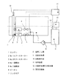
発明の実施形態であるエンジンの始動装置について、全体の概要を図1に示す。図示の例では、大型のガスエンジン1を2台のエアースターター(エアーモーター)2・3を用いて始動することとしている。
An overall outline of an engine starter according to an embodiment of the invention is shown in FIG. In the illustrated example, the
ガスエンジン1の始動をなすNo.1エアースターター2とNo.2エアースターター3は、“A”bar以下の圧力の圧縮空気を供給されることにより、各先端部のピニオン6を突出させて回転させる機能を有している。各エアースターター2・3は本体部分を支持部材(図示省略)に取り付けられていて、ピニオン6が図示左方に突出すると、エンジン1のクランク軸(図示省略)に連結されたフライホイール上のリングギヤ7に噛み合うようになっている。各エアースターター2・3には、圧縮空気の供給手段として、空気圧縮機13を付設された圧縮空気槽9が接続されていて、圧縮空気槽9と各エアースターター2・3との間には、図のように空気こし器8やNo.1開閉弁4およびNo.2開閉弁5も接続されている。No.1開閉弁4とNo.2開閉弁5はそれぞれ、エアースターター2・3へ至る空気経路を個別に開閉させ得るように設けてある。
The No. 1
No.1開閉弁4およびNo.2開閉弁5のそれぞれの開閉は、制御装置(制御手段)11が遠隔から行うようになっている。すなわち、各開閉弁4・5について開放または閉鎖させる旨の指示信号(電気または制御空気による信号)を制御装置11がそれぞれ出力し、それに基づいて機側の各アクチュエータ(図示省略)が各開閉弁4・5を個別に開閉させる。また、上記したリングギヤ7の付近に回転検出器10が設けられるとともに、圧縮空気槽9に圧力検出器12が設けられており、制御装置11には、それぞれの信号出力線も接続されている。
Each of the No. 1 on-off
図1の始動装置は、始動の開始当初は2台のエアースターター2・3を駆動してガスエンジン1を回転させ、その回転数がある程度上昇した時点で、エンジンが自力で回転数上昇し始める前にエアースターター2・3のいずれかの駆動を停止する、という始動方法を実施する。とくに、上記のように回転検出器10と圧力検出器12とが接続された制御装置11の作用により、圧縮空気の圧力に応じて、エアースターター2・3の一方を停止させるタイミング(エンジン1の回転数)を適切に定めることとしている。以下、図示の始動装置のそのような機能を詳細に説明する。
The starting device of FIG. 1 drives two
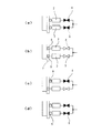
1) エンジン停止中は、開閉弁4・5はともに「閉」とする。すなわち図2(a)のように、この間、No.1・2開閉弁4・5は制御装置11によって共に「閉」であり、エアースターター2・3には圧縮空気が供給されない。この状態は、図3における<1>の区間である。
1) Open /
2) エンジン1を始動する際には、制御装置11により2台の開閉弁4・5を「開」とし、エアースターター2・3へ圧縮空気が送られる。エアースターター2・3が発生する最大の回転トルクによって、停止しているエンジン1の回転数を上昇させる。すなわち図2(b)のように、No.1・2開閉弁4・5は制御装置11によって共に「開」とし、エアースターター2・3へ圧縮空気が供給されて、ピニオン6とリングギア7が噛合って回転を開始する。
2) When the
3) エンジン1の回転数が上昇すると、起動直後に比べてエアースターター2・3に必要な回転トルクは減少するが、回転数の上昇に伴って圧縮空気の消費量は増大する。このような2)〜3)の時期は、図3においては<2>で示される区間に相当する。
3) When the rotational speed of the
4) エンジン1がある設定された回転数(切換タイミング)に達したら、制御装置11により1台の開閉弁4または5を「閉」としてエアースターター2・3のうちの1台を停止させ、もう1台は「開」のまま駆動させる。この切換以降はエアースターター2・3による空気消費量が大幅に低減する。すなわち、回転検出器10からの信号でエンジン1が設定回転数になったことが分かると、図2(c)のように、制御装置11は例えばNo.1開閉弁4のみを「閉」にする。そうすると、No.1エアースターター2のピニオン6はリングギア7との噛合いが外れ、No.2エアースターター3だけでエンジン1を駆動する。これにより、エンジン1の回転上昇する時間は遅くなるが、圧縮空気の消費量は大幅に低減する。このような状態は図3では<3>の区間として示される。
なお、圧縮空気槽9の圧力が低い場合には、上記の設定回転数を制御装置11が自動的に変更することにより、エアースターター1台でも確実に着火回転数まで回転上昇できるようにする。またさらに圧力が低い場合には、いずれの開閉弁4・5をも「閉」にせず、エアースターター2・3の2台をそのまま駆動することで、確実に起動できるように制御する(図4を参照。後述)。
4) When the
When the pressure of the
5) エンジンが自力で回転上昇を始めたら、制御装置により残りの1台の開閉弁5をも「閉」にして、エアースターター2・3によるエンジン1の始動を終了する。すなわち、エンジン1に燃料が投入・着火することで自立して回転上昇を始めた時、回転検出器10からの信号によってある設定回転数に達したことが分かると、制御装置11によって、図2(d)のようにNo.2エアースターターの開閉弁5をも「閉」にして、ピニオン6の噛合いを外し、始動終了とする。図3では<4>の区間である。
5) When the engine starts rotating and increasing by itself, the remaining one on-off
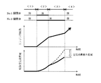
6) 圧縮空気槽9の圧力が低い場合、エアースターター2・3が発生するトルクは減少するので、設定していた切換タイミングの後にエアースターター1台でも回転低下が起こらないように、圧縮空気槽9の圧力を制御装置11で監視して、エアースターター1台ででも回転上昇できるような切換タイミング(エンジン回転数)へ自動的に変更する。図4はそのような切換タイミングの変更を示しており、圧縮空気槽9の圧力が“A”barのときには“NA”rpmでエアースターター2・3の駆動台数を2台から1台に切り換え、圧力が“B”barのときには“NB”rpmで駆動台数を1台に切り換える。
6) When the pressure in the
7) 圧縮空気槽9の低圧力設定(エアースターター1台では着火回転数まで上昇不可能な条件。空気圧力が臨界値以下のとき)においては、制御装置11はエアースターター2・3の切換を自動的に制限し、エアースターターの駆動がカットされないようにする。図4の例では、圧縮空気槽9の圧力が“C”barのときには、エアースターター2・3の駆動台数を減らさないこととしている。エアースターター1台が発生するトルクは、必要なエンジン1の起動トルク(図示破線)と差がなく、エンジン1を着火回転数まで起動できないことがあると考えられるからである。なおこの場合、エアースターター2・3の数を減らさないので、No.1・2とも同時に開閉弁4・5を「閉」とする。
7) When the
1 ガスエンジン
2・3 エアースターター(エアーモーター)
4・5 開閉弁
9 圧縮空気槽
10 回転検出器
11 制御装置(制御手段)
12 圧力検出器
1 Gas engine 2.3 Air starter (air motor)
4.5 Open /
12 Pressure detector
Claims (8)
始動の際、駆動するエアーモーターの台数を、エンジンが自力で回転数上昇し始める前に減らすこととし、
エンジンの回転数とエアーモーターに供給する圧縮空気の圧力とを検出し、
駆動するエアーモーターの台数を減らすことの決定と、当該台数を減らすときのエンジンの回転数の決定とを、検出する上記圧縮空気の圧力に応じて行うことを特徴とするエンジンの始動方法。 A method of starting an engine using a plurality of air motors,
When starting, reduce the number of air motors to be driven before the engine starts to increase its speed .
Detect the engine speed and the pressure of compressed air supplied to the air motor,
A method for starting an engine, characterized in that the determination of reducing the number of air motors to be driven and the determination of the engine speed when the number of air motors to be decreased are made according to the pressure of the compressed air to be detected.
検出する圧縮空気の圧力が一定値以下であれば、エアーモーターの台数を減らさないよう決定することを特徴とする請求項1または2に記載したエンジンの始動方法。 The lower the pressure of the compressed air to be detected, the higher the engine speed when reducing the number of air motors to drive,
3. The engine starting method according to claim 1 , wherein if the pressure of the compressed air to be detected is equal to or less than a predetermined value, it is determined not to reduce the number of air motors.
上記空気槽からの圧縮空気の供給経路にエアーモーターごとに対応づけて設けられた開閉弁と、始動の際エンジンが自力で回転数上昇し始める前に、圧縮空気を供給するエアーモーターの台数を減らすべく上記開閉弁のいずれかに閉鎖の指示を出力する制御手段とを有し、
エンジン回転数の検出器と圧縮空気圧力の検出器とが付設されて上記制御手段に接続されているとともに、
当該制御手段が、開閉弁のいずれかに閉鎖の指示を出力するときのエンジン回転数を、上記検出器にて検出される空気圧力に応じて決定し、上記検出器にて検出されるエンジン回転数が当該決定された値になったとき上記開閉弁のいずれかに閉鎖の指示を出力するものであることを特徴とするエンジンの始動装置。 An engine starter having an engine, a plurality of air motors for starting the engine, and an air tank for supplying compressed air to the air motors,
The number of air motors that supply compressed air before the engine starts to increase its rotational speed by itself when starting, and the open / close valves provided in association with the compressed air supply path from the air tank. Control means for outputting a closing instruction to any of the on-off valves in order to reduce ,
An engine speed detector and a compressed air pressure detector are attached and connected to the control means,
The control means determines the engine speed when outputting a closing instruction to any of the on-off valves according to the air pressure detected by the detector, and the engine speed detected by the detector An engine starter characterized in that when the number reaches the determined value, a closing instruction is output to any of the on-off valves.
Priority Applications (8)
| Application Number | Priority Date | Filing Date | Title |
|---|---|---|---|
| JP2008100800A JP5118541B2 (en) | 2008-04-08 | 2008-04-08 | ENGINE START METHOD AND START DEVICE |
| EP09730208.7A EP2270329A4 (en) | 2008-04-08 | 2009-03-16 | Method and device for starting engine |
| KR1020107014853A KR101217922B1 (en) | 2008-04-08 | 2009-03-16 | Method and device for starting engine |
| US12/936,865 US8661834B2 (en) | 2008-04-08 | 2009-03-16 | Method and apparatus for starting engine |
| PCT/JP2009/001159 WO2009125542A1 (en) | 2008-04-08 | 2009-03-16 | Method and device for starting engine |
| AU2009235000A AU2009235000B2 (en) | 2008-04-08 | 2009-03-16 | Method and apparatus for starting engine |
| RU2010145123/06A RU2454562C1 (en) | 2008-04-08 | 2009-03-16 | Method and device for engine starting |
| BRPI0906322-6A BRPI0906322A2 (en) | 2008-04-08 | 2009-03-16 | Method of starting an engine using a plurality of pneumatic motors and engine starting apparatus. |
Applications Claiming Priority (1)
| Application Number | Priority Date | Filing Date | Title |
|---|---|---|---|
| JP2008100800A JP5118541B2 (en) | 2008-04-08 | 2008-04-08 | ENGINE START METHOD AND START DEVICE |
Publications (2)
| Publication Number | Publication Date |
|---|---|
| JP2009250150A JP2009250150A (en) | 2009-10-29 |
| JP5118541B2 true JP5118541B2 (en) | 2013-01-16 |
Family
ID=41161680
Family Applications (1)
| Application Number | Title | Priority Date | Filing Date |
|---|---|---|---|
| JP2008100800A Expired - Fee Related JP5118541B2 (en) | 2008-04-08 | 2008-04-08 | ENGINE START METHOD AND START DEVICE |
Country Status (8)
| Country | Link |
|---|---|
| US (1) | US8661834B2 (en) |
| EP (1) | EP2270329A4 (en) |
| JP (1) | JP5118541B2 (en) |
| KR (1) | KR101217922B1 (en) |
| AU (1) | AU2009235000B2 (en) |
| BR (1) | BRPI0906322A2 (en) |
| RU (1) | RU2454562C1 (en) |
| WO (1) | WO2009125542A1 (en) |
Families Citing this family (11)
| Publication number | Priority date | Publication date | Assignee | Title |
|---|---|---|---|---|
| KR101185402B1 (en) | 2010-09-01 | 2012-09-24 | 삼성중공업 주식회사 | Air supply system of ship and control method for the same |
| KR101315157B1 (en) * | 2011-12-27 | 2013-10-07 | 삼성중공업 주식회사 | Air storage tank for starting main engine and generating engine of ship |
| US8776753B2 (en) * | 2011-12-30 | 2014-07-15 | Remy Technologies Llc | Dual synchronized starter motors |
| FI20125501L (en) * | 2012-05-10 | 2013-11-11 | Waertsilae Finland Oy | Pneumatic system for a piston engine |
| KR101665330B1 (en) * | 2012-09-27 | 2016-10-12 | 대우조선해양 주식회사 | Air system for offshore structures |
| JP6045424B2 (en) | 2013-03-29 | 2016-12-14 | 三菱重工業株式会社 | Gas internal combustion engine starter |
| WO2015156761A1 (en) * | 2014-04-07 | 2015-10-15 | Ge Aviation Systems Llc | Method for slow starting a reciprocating engine with a pneumatic starter while diagnosing the presence of a hydrostatic lock |
| CN105317610A (en) * | 2015-08-03 | 2016-02-10 | 湖北江山专用汽车有限公司 | Pneumatic interlocking protecting device of diesel engine for engineering machinery |
| CN105569902B (en) * | 2015-12-31 | 2018-11-30 | 泰豪科技股份有限公司 | One-cylinder diesel generator containing air pressure starter |
| US10480417B2 (en) * | 2016-07-14 | 2019-11-19 | Hamilton Sundstrand Corporation | Air turbine start system |
| RU177703U1 (en) * | 2017-04-04 | 2018-03-06 | Российская Федерация, от имени которой выступает Министерство промышленности и торговли Российской Федерации (Минпромторг России) | ICE STARTING SYSTEM IN THE CONDITIONS OF LOW TEMPERATURES |
Family Cites Families (13)
| Publication number | Priority date | Publication date | Assignee | Title |
|---|---|---|---|---|
| US4494499A (en) * | 1983-05-09 | 1985-01-22 | Tech Development Inc. | System and apparatus providing a two step starting cycle for diesel engines using a pneumatic starter |
| SU1288335A1 (en) * | 1985-09-10 | 1987-02-07 | Grachev Evgenij F | Device for starting internal combustion engine |
| DE3604284A1 (en) * | 1986-02-12 | 1987-08-13 | Duesterloh Gmbh | COMPRESSED AIR STARTING SYSTEM |
| DE3736110A1 (en) * | 1987-10-26 | 1989-05-11 | Porsche Ag | STARTING ARRANGEMENT FOR A HELICOPTER |
| JPH02277962A (en) * | 1989-04-19 | 1990-11-14 | Yanmar Diesel Engine Co Ltd | Air motor starting method of internal combustion engine |
| US5435125A (en) * | 1994-06-15 | 1995-07-25 | United Technologies Corporation | Redundant engine starting system |
| RU2120056C1 (en) * | 1997-04-09 | 1998-10-10 | Александр Николаевич Чехунов | Method and device for starting the engine by means of pneumatic starter |
| JP3285531B2 (en) * | 1998-03-20 | 2002-05-27 | 三菱電機株式会社 | Starting device for engine with motor generator |
| JP3414310B2 (en) | 1998-09-25 | 2003-06-09 | トヨタ自動車株式会社 | Engine start control device |
| KR19990068406A (en) | 1999-05-17 | 1999-09-06 | 방효륭 | Aaaaa |
| JP2002349401A (en) * | 2001-05-23 | 2002-12-04 | Honda Motor Co Ltd | Starting system for internal combustion engine |
| JP2007092640A (en) | 2005-09-29 | 2007-04-12 | Hitachi Ltd | Diesel electric power generation facility and its operation method |
| JP4421567B2 (en) * | 2006-03-17 | 2010-02-24 | 富士重工業株式会社 | Engine starter for hybrid vehicle |
-
2008
- 2008-04-08 JP JP2008100800A patent/JP5118541B2/en not_active Expired - Fee Related
-
2009
- 2009-03-16 KR KR1020107014853A patent/KR101217922B1/en not_active IP Right Cessation
- 2009-03-16 WO PCT/JP2009/001159 patent/WO2009125542A1/en active Application Filing
- 2009-03-16 RU RU2010145123/06A patent/RU2454562C1/en not_active IP Right Cessation
- 2009-03-16 US US12/936,865 patent/US8661834B2/en not_active Expired - Fee Related
- 2009-03-16 BR BRPI0906322-6A patent/BRPI0906322A2/en not_active IP Right Cessation
- 2009-03-16 EP EP09730208.7A patent/EP2270329A4/en not_active Withdrawn
- 2009-03-16 AU AU2009235000A patent/AU2009235000B2/en not_active Ceased
Also Published As
| Publication number | Publication date |
|---|---|
| AU2009235000A1 (en) | 2009-10-15 |
| KR20100087238A (en) | 2010-08-03 |
| BRPI0906322A2 (en) | 2015-07-07 |
| RU2454562C1 (en) | 2012-06-27 |
| WO2009125542A1 (en) | 2009-10-15 |
| AU2009235000B2 (en) | 2011-12-08 |
| RU2010145123A (en) | 2012-05-20 |
| KR101217922B1 (en) | 2013-01-02 |
| EP2270329A1 (en) | 2011-01-05 |
| JP2009250150A (en) | 2009-10-29 |
| US8661834B2 (en) | 2014-03-04 |
| US20110094323A1 (en) | 2011-04-28 |
| EP2270329A4 (en) | 2015-08-12 |
Similar Documents
| Publication | Publication Date | Title |
|---|---|---|
| JP5118541B2 (en) | ENGINE START METHOD AND START DEVICE | |
| EP3205848B1 (en) | Auxiliary drive bowed rotor prevention system for a gas turbine engine | |
| EP3205849A1 (en) | Auxiliary drive bowed rotor prevention system for a gas turbine engine through an engine accessory | |
| JP2012149646A (en) | Control of engine including electrically controlled turbocharger | |
| US7938703B2 (en) | Watercraft propulsion system and operating method | |
| JP4868523B2 (en) | Auto choke device in engine | |
| KR20090013872A (en) | Limp home mode drive method for hybrid electric vehicle and engine clutch control hydraulic system for the same | |
| JP2007032388A (en) | Start control device for internal combustion engine | |
| EP3895980B1 (en) | Control system for marine propulsion device, control method for the same, and marine vessel | |
| JP2008121606A (en) | Engine starting device | |
| JP5394569B2 (en) | Engine starter and control method for engine starter | |
| KR100759059B1 (en) | Controller controlling electric machine operated to start internal combustion engine | |
| JP4169952B2 (en) | Gas turbine engine restart method and restart device used therefor | |
| JP2010077822A (en) | Control system for fuel injection engine | |
| JP6394312B2 (en) | Control system for idling stop of internal combustion engine | |
| JP2019127910A (en) | Outboard motor | |
| US12018578B1 (en) | Core turning system | |
| US20240344466A1 (en) | Core turning system | |
| JP6409162B1 (en) | Supercharger surplus power recovery device for internal combustion engine and ship | |
| JPH07233734A (en) | Fuel pressure holding device for gas turbine | |
| JP2005330929A (en) | Diagnostic device of secondary air feeder | |
| JP2006352974A (en) | Controller for generator for vehicle | |
| KR20230082310A (en) | Air starting motor with slow turning function | |
| JP2002322919A (en) | Operating method of gas turbine generator and operating equipment | |
| JP2007321669A (en) | Engine control device for working machine |
Legal Events
| Date | Code | Title | Description |
|---|---|---|---|
| A621 | Written request for application examination |
Free format text: JAPANESE INTERMEDIATE CODE: A621 Effective date: 20110214 |
|
| A131 | Notification of reasons for refusal |
Free format text: JAPANESE INTERMEDIATE CODE: A131 Effective date: 20120703 |
|
| A521 | Request for written amendment filed |
Free format text: JAPANESE INTERMEDIATE CODE: A523 Effective date: 20120828 |
|
| TRDD | Decision of grant or rejection written | ||
| A01 | Written decision to grant a patent or to grant a registration (utility model) |
Free format text: JAPANESE INTERMEDIATE CODE: A01 Effective date: 20121016 |
|
| A01 | Written decision to grant a patent or to grant a registration (utility model) |
Free format text: JAPANESE INTERMEDIATE CODE: A01 |
|
| A61 | First payment of annual fees (during grant procedure) |
Free format text: JAPANESE INTERMEDIATE CODE: A61 Effective date: 20121019 |
|
| R150 | Certificate of patent or registration of utility model |
Free format text: JAPANESE INTERMEDIATE CODE: R150 |
|
| FPAY | Renewal fee payment (event date is renewal date of database) |
Free format text: PAYMENT UNTIL: 20151026 Year of fee payment: 3 |
|
| LAPS | Cancellation because of no payment of annual fees |