JP5115822B2 - Fuel injection control device for in-cylinder injection engine - Google Patents
Fuel injection control device for in-cylinder injection engine Download PDFInfo
- Publication number
- JP5115822B2 JP5115822B2 JP2008299585A JP2008299585A JP5115822B2 JP 5115822 B2 JP5115822 B2 JP 5115822B2 JP 2008299585 A JP2008299585 A JP 2008299585A JP 2008299585 A JP2008299585 A JP 2008299585A JP 5115822 B2 JP5115822 B2 JP 5115822B2
- Authority
- JP
- Japan
- Prior art keywords
- fuel
- engine
- pressure
- fuel pressure
- stop mode
- Prior art date
- Legal status (The legal status is an assumption and is not a legal conclusion. Google has not performed a legal analysis and makes no representation as to the accuracy of the status listed.)
- Expired - Fee Related
Links
Images


Description
この発明は筒内噴射式エンジンの燃料噴射制御装置に係り、特に、燃焼室内に直接燃料を噴射する燃料噴射弁、高圧燃料ポンプおよび、高圧の燃料を蓄圧するデリバリーパイプを備えた燃料噴射制御装置について、エンジンの停止時に燃料噴射弁から燃焼室への燃料漏れを低減することができる筒内噴射式エンジンの燃料噴射制御装置に関する。 The present invention relates to a fuel injection control device for a direct injection engine, and in particular, a fuel injection control device including a fuel injection valve that directly injects fuel into a combustion chamber, a high-pressure fuel pump, and a delivery pipe that accumulates high-pressure fuel. The present invention relates to a fuel injection control device for a direct injection type engine that can reduce fuel leakage from a fuel injection valve to a combustion chamber when the engine is stopped.
筒内直噴式エンジン(以下、「エンジン」と記す。)は、燃焼室内に直接燃料を噴射する燃料噴射弁と、高圧燃料ポンプと、前記高圧燃料ポンプから送られた燃料を前記燃料噴射弁へ供給するデリバリパイプとを備え、燃料噴射制御装置により燃料圧力を制御して燃焼室内に直接燃料を噴射する。エンジンは、通常運転時からのエンジン停止時において、燃料噴射弁からの噴射が無くなることで、デリバリパイプ内の燃料圧力が残圧として燃料噴射弁、高圧燃料ポンプに作用する。デリバリパイプ内の燃料は、時間経過とともに、この残圧の作用によって燃料噴射弁の先端部(ニードルおよびシート)から燃焼室内に漏れることで、次回のエンジン始動時に排ガス性能の悪化を引き起こす問題がある。 An in-cylinder direct injection engine (hereinafter referred to as “engine”) includes a fuel injection valve that directly injects fuel into a combustion chamber, a high-pressure fuel pump, and fuel sent from the high-pressure fuel pump to the fuel injection valve. A delivery pipe for supplying the fuel, and the fuel pressure is controlled by a fuel injection control device to inject the fuel directly into the combustion chamber. When the engine is stopped after the normal operation, the fuel is not injected from the fuel injection valve, so that the fuel pressure in the delivery pipe acts as a residual pressure on the fuel injection valve and the high-pressure fuel pump. Over time, the fuel in the delivery pipe leaks into the combustion chamber from the tip of the fuel injection valve (needle and seat) due to the action of this residual pressure, which causes a problem of deteriorating exhaust gas performance at the next engine start. .
従来の筒内噴射式エンジンの燃料噴射制御装置には、通常のエンジン停止時には、デリバリパイプの燃料を燃料タンクに戻す電磁リリーフ弁を開いて燃料圧力を低下させることで燃焼室内に漏れる燃料量を低減し、エンジンのアイドルストップ時には、電磁リリーフ弁を閉じて燃料圧力を高い圧力に保持することで再始動性を円滑に行うものがある。
また、従来の筒内噴射式エンジンの燃料噴射制御装置には、エンジン停止直前かどうかを判断し、停止直前と判断した場合は、あらかじめ目標燃料圧力を低下させることで、エンジン停止中の燃料噴射弁からの燃料漏れを減少させるものがある。
さらに、従来の筒内噴射式エンジンの燃料噴射制御装置には、エンジン停止条件の成立時に、燃料供給量を低下させるとともに燃料噴射弁からの燃料噴射を継続させて、デリバリパイプ内の燃料圧力を目標燃料圧力に低下させてから、エンジンを停止させるものがある。
ところが、エンジンが停止される状況は、運転者の操作による通常の停止や制御によるアイドルストップだけでなく、熱害による停止がある。 However, the situation in which the engine is stopped includes not only a normal stop by a driver's operation and an idle stop by control, but also a stop by heat damage.
このため、特許文献1に記載の燃料噴射制御装置は、通常のエンジン停止時やエンジンのアイドルストップ時の燃料漏れを低減することはできる一方で、熱害によるエンジン停止時の燃料漏れに対応できない問題がある。また、特許文献1に記載の燃料噴射制御装置は、デリバリパイプと燃料タンクとを連絡する戻り通路の途中に電磁リリーフ弁を設けて開閉制御しているため、構造や制御が煩雑になる問題がある。 For this reason, the fuel injection control device described in Patent Document 1 can reduce fuel leakage at the time of normal engine stop or engine idle stop, but cannot cope with fuel leakage at the time of engine stop due to heat damage. There's a problem. In addition, the fuel injection control device described in Patent Document 1 is provided with an electromagnetic relief valve in the middle of a return path that connects the delivery pipe and the fuel tank, so that the opening and closing control is performed. is there.
また、特許文献2に記載の燃料噴射制御装置は、エンジン停止直前かどうかを判断する必要があり、誤判定した場合に燃料噴射弁噴霧品質の低下が懸念されるだけでなく、熱害再始動時(デリバリパイプ内の燃料中に気泡が発生して再始動が困難となる)においては、燃料漏れに対する効果が期待できない問題がある。 In addition, the fuel injection control device described in Patent Document 2 needs to determine whether or not it is immediately before the engine is stopped, and in the case of erroneous determination, not only is there a concern about a decrease in fuel injection valve spray quality, but also thermal restart At times (bubbles are generated in the fuel in the delivery pipe and restarting becomes difficult), there is a problem that the effect on fuel leakage cannot be expected.
さらに、特許文献3に記載の燃料噴射制御装置は、熱害再始動時には燃料漏れに対する効果が期待できないとともに、アイドルストップ制御中(すぐに再始動するので燃料圧力を下げることができない)にも漏れに対する効果が期待できない問題がある。 Furthermore, the fuel injection control device described in Patent Document 3 cannot be expected to have an effect on fuel leakage at the time of thermal damage restart, and also leaks during idle stop control (because it restarts immediately and fuel pressure cannot be reduced). There is a problem that the effect on can not be expected.
この発明は、エンジンがどのような状況下で停止されたかに応じて、停止時における目標燃料圧力の値を設定することで、エンジン停止後の次のエンジン始動時における始動性能を落とすことなく、燃料供給系から燃焼室に燃料が漏れるのを防止し、始動時における排気ガス浄化性能の向上に貢献することを目的とする。 This invention sets the value of the target fuel pressure at the time of stop according to under what circumstances the engine is stopped, so that the start performance at the time of the next engine start after engine stop is not reduced. An object is to prevent fuel from leaking from the fuel supply system into the combustion chamber and to contribute to the improvement of exhaust gas purification performance at the time of starting.
この発明は、燃焼室内に直接燃料を噴射する燃料噴射弁と、高圧燃料ポンプと、前記高圧燃料ポンプから送られた燃料を前記燃料噴射弁へ供給するデリバリパイプとを備えた筒内噴射式エンジンの燃料噴射制御装置において、前記デリバリパイプ内の燃料圧力を検出する燃料圧力検出手段を備え、前記燃料圧力検出手段で検出された燃料圧力が、目標燃料圧力になるように制御する燃料圧力制御手段を備え、予め前記エンジンが停止した理由毎に設定された複数のエンジン停止モードとして、運転者の意志に基づいてエンジンを停止する通常停止モードと、エンジン運転状態制御手段からの指令によりエンジンを停止するアイドルストップモードと、燃料温度が上昇し次回のエンジン再始動時に影響を与える可能性がある状態でエンジンを停止する熱害停止モードとを備え、どのエンジン停止モードを選択し、エンジンが停止されたのかを判定するエンジン停止モード判定手段を備え、前記エンジン停止モード判定手段で判定されたエンジン停止モードに応じて、前記燃料圧力制御手段により制御する目標燃料圧力の値を設定するエンジン停止時燃料圧力制御手段を備え、前記通常停止モード時には、目標燃料圧力をアイドル時燃料圧力よりも低く設定し、前記アイドルストップモード時には、目標燃料圧力をアイドル時燃料圧力よりも高く設定し、前記熱害停止モード時には、目標燃料圧力をエンジン水温に応じてアイドル時燃料圧力よりも高く設定し、燃料圧力と目標燃料圧力との差分が所定未満となった時に燃料カットおよび点火カットを行い、その後にエンジンの停止の判定を行うことを特徴とする。 The present invention relates to an in-cylinder injection engine that includes a fuel injection valve that directly injects fuel into a combustion chamber, a high-pressure fuel pump, and a delivery pipe that supplies fuel sent from the high-pressure fuel pump to the fuel injection valve. The fuel injection control apparatus of claim 1, further comprising a fuel pressure detecting means for detecting a fuel pressure in the delivery pipe, wherein the fuel pressure detected by the fuel pressure detecting means is controlled to become a target fuel pressure. As a plurality of engine stop modes set in advance for each reason the engine has stopped, a normal stop mode for stopping the engine based on the driver's will and a command from the engine operating state control means to stop the engine To stop the engine in the idle stop mode in which the fuel temperature rises and may affect the next engine restart. And a heat damage stop mode, selecting any engine stop mode, an engine stop mode judging means for judging whether the engine is stopped, depending on the determined engine stop mode in the engine stop mode determination unit An engine stop fuel pressure control means for setting a target fuel pressure value controlled by the fuel pressure control means ; in the normal stop mode, the target fuel pressure is set lower than the idle fuel pressure; In the mode, the target fuel pressure is set higher than the idling fuel pressure. In the thermal damage stop mode, the target fuel pressure is set higher than the idling fuel pressure according to the engine water temperature, and the fuel pressure, the target fuel pressure, The fuel cut and ignition cut are performed when the difference between the two is less than the predetermined value, and then the engine is stopped. And performing.
この発明の筒内噴射式エンジンの燃料噴射制御装置は、エンジンがどのような状況下で停止されたかに応じて、停止時における目標燃料圧力の値を設定しているので、エンジン停止後の次のエンジン始動時における始動性能を落とすことなく、燃料供給系から燃焼室に燃料が漏れるのを防ぐことが可能である。
これにより、この発明の筒内噴射式エンジンの燃料噴射制御装置は、始動時における排気ガス浄化性能の向上に貢献できる。
In the fuel injection control device for a direct injection type engine according to the present invention, the target fuel pressure value at the time of stopping is set according to under what circumstances the engine is stopped. It is possible to prevent the fuel from leaking from the fuel supply system to the combustion chamber without degrading the starting performance when starting the engine.
As a result, the fuel injection control device for a direct injection engine according to the present invention can contribute to the improvement of the exhaust gas purification performance at the time of starting.
この発明の筒内噴射式エンジンの燃料噴射制御装置は、エンジンがどのような状況下で停止されたかに応じて、停止時における目標燃料圧力の値を設定することで、燃料供給系から燃焼室に燃料が漏れるのを防ぐものである。
以下図面に基づいて、この発明の実施例を説明する。
A fuel injection control device for a direct injection type engine according to the present invention sets a target fuel pressure value at the time of stopping according to under what circumstances the engine is stopped, so that the fuel supply system can This prevents the fuel from leaking.
Embodiments of the present invention will be described below with reference to the drawings.
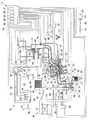
図1〜図13は、この発明の実施例を示すものである。図1は筒内噴射式エンジンの燃料噴射制御装置のシステム構成図、図2は燃料圧力と漏れ量の関係を示す図、図3は時間と漏れ量の関係を示す図、図4はエンジン停止ルーチンのフローチャート、図5は停止モード判定ルーチンのフローチャート、図6は通常停止モードルーチンのフローチャート、図7は通常停止モードの水温による目標燃料圧力のテーブルを示す図、図8は通常停止モードのエンジン回転数による目標燃料圧力の差分判定閾値のMAPを示す図、図9はアイドルストップモードルーチンのフローチャート、図10はアイドルストップモードのエンジン回転数による目標燃料圧力の差分判定閾値のMAPを示す図、図11は熱害停止モードルーチンのフローチャート、図12は熱害停止モードの水温による目標燃料圧力のテーブルを示す図、図13は熱害停止モードのエンジン回転数による目標燃料圧力の差分判定閾値のMAPである。
図1において、1は複数の気筒を有する筒内噴射式エンジン(以下「エンジン」と記す。)、2はシリンダブロック、3はシリンダヘッド、4はシリンダヘッドカバー、5はピストン、6は燃焼室、7は吸気ポート、8は排気ポートである。車両に搭載されるエンジン1は、シリンダヘッド3に吸気カム軸9及び排気カム軸10を軸支し、これら吸気カム軸9の吸気カム11及び排気カム軸10の排気カム12で夫々駆動される吸気バルブ13及び排気バルブ14を設けている。吸気バルブ13及び排気バルブ14は、各気筒の燃焼室6に連通する吸気ポート7及び排気ポート8を夫々開閉する。
エンジン1は、吸気装置15として、エアクリーナ16と吸気管17とスロットルボディ18とサージタンク19と吸気マニホルド20とを順次に接続し、吸気ポート7に連通する吸気通路21を設けている。スロットルボディ18の吸気通路21には、スロットルバルブ22を設けている。また、エンジン1は、排気装置23として、排気マニホルド24と触媒コンバータ25と排気管26とを順次に接続し、排気ポート8に連通する排気通路27を設けている。
このエンジン1には、過給機(ターボチャージャ)28を設けている。過給機28は、吸気管17の途中と排気マニホルド24及び触媒コンバータ25間とに過給機ケース29を配設し、過給機ケース29内の吸気通路21にコンプレッサ30を設け、過給機ケース29内の排気通路27にコンプレッサ30を駆動するタービン31を設けている。
前記エンジン1は、タービン31を迂回して排気通路27を連通するバイパス通路32を設け、バイパス通路32を開閉するウエイストゲートバルブ33を設け、ウエイストゲートバルブ33を開閉動作するウエイストゲートアクチュエータ34を設け、ウエイストゲートアクチュエータ34を動作制御するウエイストゲート制御バルブ35を設けている。ウエイストゲート制御バルブ35は、コンプレッサ30下流側の吸気通路21からウエイストゲートアクチュエータ34に導入される作動圧の一部をコンプレッサ30上流側に逃がして調整することによりウエイストゲートアクチュエータ34の動作を制御し、ウエイストゲートバルブ33を開閉動作して過給圧を設定過給圧に制御する。
また、エンジン1は、コンプレッサ30の上流側及び下流側の吸気通路21を連通するエアバイパス通路36を設け、エアパイパス通路36を開閉するエアバイパスバルブ37を設け、エアバイパスバルブ37を開閉動作するエアバイパスアクチュエータ38を設け、エアバイパスアクチュエータ38を動作制御するエアバイパス制御バルブ39を設けている。エアバイパス制御バルブ39は、コンプレッサ30下流側の吸気通路21からエアバイパスアクチュエータ38に導入される作動圧を調整することによりエアバイパスアクチュエータ38の動作を制御し、スロットルバルブ22の急閉時にエアバイパスバルブ37を開放動作してコンプレッサ30のサージングを防止する。このエンジン1は、コンプレッサ30とスロットルボディ18との間の吸気管17に、過給機28で過給された吸入空気を冷却するインタクーラ40を設けている。
1 to 13 show an embodiment of the present invention. FIG. 1 is a system configuration diagram of a fuel injection control device for a direct injection engine, FIG. 2 is a diagram showing a relationship between fuel pressure and a leak amount, FIG. 3 is a diagram showing a relationship between time and a leak amount, and FIG. FIG. 5 is a flowchart of a stop mode determination routine, FIG. 6 is a flowchart of a normal stop mode routine, FIG. 7 is a table showing a target fuel pressure according to water temperature in the normal stop mode, and FIG. FIG. 9 is a flow chart of an idle stop mode routine, FIG. 10 is a diagram showing a target fuel pressure difference determination threshold MAP according to engine speed in the idle stop mode, FIG. 11 is a flowchart of the thermal damage stop mode routine, and FIG. It shows a table, Fig. 13 is a MAP of difference determination threshold value of the target fuel pressure according to engine speed heat damage stop mode.
In FIG. 1, 1 is a cylinder injection engine having a plurality of cylinders (hereinafter referred to as “engine”), 2 is a cylinder block, 3 is a cylinder head, 4 is a cylinder head cover, 5 is a piston, 6 is a combustion chamber, 7 is an intake port, and 8 is an exhaust port. An engine 1 mounted on a vehicle supports an
In the engine 1, as an
The engine 1 is provided with a supercharger (turbocharger) 28. The
The engine 1 is provided with a
Further, the engine 1 is provided with an
このエンジン1は、燃焼室6内に直接燃料を供給可能な燃料供給装置41として、燃料タンク42内に燃料をエンジン1側に圧送する電磁式の低圧燃料ポンプ43を設け、この低圧燃料ポンプ43の吐出側にフィルタ44と圧力レギュレータ45とを介して低圧燃料供給通路46の一端側を接続している。圧力レギュレータ45は、低圧燃料ポンプ43の吐出する燃料の一部を燃料タンク42に戻すことで吐出量を調整し、低圧燃料供給通路46の燃料圧力を低圧の設定値に維持する。前記低圧燃料供給通路46の他端側は、機械式の高圧燃料ポンプ47の吸入側に接続している。高圧燃料ポンプ47は、シリンダヘッド3に取り付けられ、吸気カム軸9の回転によって機械的に駆動され、低圧燃料供給通路46から供給された低圧の燃料を高圧にしてエンジン1側に圧送する。
前記高圧燃料ポンプ47は、吐出側に高圧燃料供給通路48の一端側を接続している。高圧燃料供給通路48の他端側は、デリバリパイプ49に接続している。高圧燃料供給通路48の途中には、デリバリパイプ49から高圧燃料ポンプ47への燃料の逆流を規制する逆止弁50を設けている。デリバリパイプ49には、シリンダヘッド3に取り付けられた各気筒毎の燃料噴射弁51を接続している。デリバリパイプ49は、高圧燃料供給通路48から供給された高圧の燃料を各燃料噴射弁51に分配する。燃料噴射弁51は、燃焼室6に臨ませてシリンダヘッド3に取り付けられ、燃料を燃焼室6内に直接噴射する。
また、高圧燃料ポンプ47は、吐出側に、前記逆止弁50よりも高圧燃料ポンプ側の高圧燃料供給通路48に連通するように、燃料戻り通路52の一端側を接続している。燃料戻り通路52は、他端側を前記燃料タンク42内に開口している。高圧燃料ポンプ47は、高圧燃料供給通路48に対して、燃料戻り通路52を開閉するスピル弁53を備えている。スピル弁53は、後述の制御手段78に備えた燃料圧力制御手段85でフィードバック制御され、高圧燃料ポンプ47の吐出する燃料の一部を燃料戻り通路52により燃料タンク42に戻すことで吐出量を調整し、高圧燃料供給通路48の燃料圧力を高圧の設定値(目標燃料圧力)に維持する。
前記燃料タンク42には、2ウェイチェックバルブ54を介してエバポ通路55の一端側を接続している。エバポ通路55は、他端側をキャニスタ56に接続している。キャニスタ56には、パージ通路57の一端側を接続している。パージ通路57は、他端側をスロットルバルブ22よりも下流側の吸気通路21に連通している。パージ通路57の途中には、パージ制御バルブ58を設けている。パージ制御バルブ58は、キャニスタ56に吸着した燃料蒸発ガスのエンジン1への導入量(パージ量)を制御する。
The engine 1 is provided with an electromagnetic low-
The high-
The high-
One end of an
このエンジン1は、点火装置59として、シリンダヘッドカバー4に各気筒毎のイグニションコイル60を取り付けている。イグニションコイル60は、各気筒の燃焼室6に臨ませた点火プラグに高電圧を供給し、飛び火させる。
また、このエンジン1は、シリンダヘッドカバー4内にPCVバルブ61を介してタンク側ブローバイガス通路62の一端側を連通している。タンク側ブローバイガス通路62は、他端側をサージタンク19の吸気通路21に連通している。このエンジン1は、シリンダヘッドカバー4内にクリーナ側ブローバイガス通路63の一端側を連通している。クリーナ側ブローバイガス通路63は、他端側をエアクリーナ16内に連通している。
また、このエンジン1は、スロットルバルブ22を迂回して吸気通路21を連通するアイドル空気通路64を設けている。このアイドル空気通路64の途中には、吸気通路21をバイパスしてアイドル空気通路64を通るアイドル空気量を調整するアイドル空気量制御バルブ65を設けている。
さらに、このエンジン1は、一端側を排気マニホルド24の排気通路27に連通し、他端側をサージタンク19の吸気通路21に連通するEGR通路66を設けている。このEGR通路66の途中には、吸気通路21に還流される排気ガス量(EGR量)を調整するEGR制御バルブ67を設けている。
In the engine 1, an ignition coil 60 for each cylinder is attached to the cylinder head cover 4 as an
Further, the engine 1 communicates with one end side of the tank side blow-by
The engine 1 also includes an
Further, the engine 1 is provided with an
このエンジン1には、スロットルバルブ22のスロットル開度を検出するスロットル開度センサ68を設け、スロットルバルブ22下流側の吸気管圧力を検出する吸気圧センサ69を設け、吸気温度を検出する吸気温センサ70を設け、エンジン1のエンジン回転数を検出し且つクランク位置を判別するためのクランク角を検出するクランク角センサ71を設け、エンジン1の気筒を判別し且つ吸気カム軸9のカム位置を判別するためのカム角を検出するカム角センサ72を設け、デリバリパイプ49内の燃料圧力を検出する燃料圧力検出手段である燃料圧力センサ73を設け、ノッキングを検出するノッキングセンサ74を設け、冷却水温度を検出する水温センサ75を設け、排気中の酸素濃度を検出するO2センサ76を設けている。
前記ウエイストゲート制御バルブ35とエアバイパス制御バルブ39と低圧燃料ポンプ43と燃料噴射弁51とスピル弁53とパージ制御バルブ58とイグニションコイル60とアイドル空気量制御バルブ65とEGR制御バルブ67とスロットル開度センサ68と吸気圧センサ69と吸気温センサ70とクランク角センサ71とカム角センサ72と燃料圧力センサ73とノッキングセンサ74と水温センサ75とO2センサ76とは、エンジン1の燃料噴射制御装置77を構成する制御手段78に接続している。制御手段78には、メインスイッチ79及びフューズ80を介してバッテリ81を接続している。なお、燃料噴射弁51は、駆動電圧を高くする燃料噴射弁駆動部82を介して制御手段78に接続している。
エンジン1の燃料噴射制御装置77は、燃焼室6内に直接燃料を噴射する燃料噴射弁51と、高圧燃料ポンプ47と、この高圧燃料ポンプ47から送られた燃料を燃料噴射弁51へ供給するデリバリパイプ49とを備え、各種センサ68〜76からの検出信号を入力する制御手段78によって、燃料噴射弁51の噴射燃料量を制御する燃料噴射制御機能を有している。燃料噴射制御機能は、制御手段78の燃料噴射制御手段83により実行される。燃料噴射制御手段83は、エンジン1の内部状態を含む様々な状態に応じて要求される燃料を燃焼室6内に供給するように燃料噴射弁51を制御する。
また、エンジン1の燃料噴射制御装置77は、各種センサ68〜76からの検出信号を入力する制御手段78によって、エンジン1の自動停止・自動始動を制御するエンジン運転状態制御機能を有している。エンジン運転状態制御機能は、制御手段78のエンジン運転状態制御手段84により実行される。エンジン運転状態制御手段84は、自動停止条件・自動始動条件によりエンジン1を停止・始動する指令を出力し、エンジン1を自動的に停止(アイドルストップ)・始動するように燃料噴射弁51やイグニションコイル60を制御する。
The engine 1 is provided with a
The
The fuel
The fuel
このエンジン1の燃料噴射制御装置77は、前記デリバリパイプ49内の燃料圧力を検出する燃料圧力検出手段として燃料圧力センサ73を備え、前記燃料圧力センサ73で検出された燃料圧力が、目標燃料圧力になるように制御する燃料圧力制御手段85を前記制御手段78に備え、予め前記エンジン1が停止した理由毎に設定された複数のエンジン停止モードの内、どのエンジン停止モードを選択し、エンジン1が停止されたのかを判定するエンジン停止モード判定手段86を前記制御手段78に備え、前記エンジン停止モード判定手段86で判定されたエンジン停止モードに応じて、前記燃料圧力制御手段85により制御する目標燃料圧力の値を設定するエンジン停止時燃料圧力制御手段87を前記制御手段78に備えている。
前記エンジン停止モード判定手段86が判定するエンジン停止モードは、運転者の意志に基づいてエンジン1を停止する通常停止モードと、前記エンジン運転状態制御手段84からの指令によりエンジン1を停止するアイドルストップモードと、燃料温度が上昇し次回のエンジン再始動時に影響を与える可能性がある状態でエンジン1を停止する熱害停止モードとから構成されている。
前記エンジン停止時燃料圧力制御手段87は、前記通常停止モード時には、目標燃料圧力をアイドル時燃料圧力よりも低く設定し、前記アイドルストップモード時には、目標燃料圧力をアイドル時燃料圧力よりも高く設定し、前記熱害停止モード時には、目標燃料圧力をエンジン水温に応じてアイドル時燃料圧力よりも高く設定している。
The fuel
The engine stop mode determined by the engine stop
The engine stop fuel pressure control means 87 sets the target fuel pressure lower than the idling fuel pressure in the normal stop mode, and sets the target fuel pressure higher than the idling fuel pressure in the idling stop mode. In the thermal damage stop mode, the target fuel pressure is set higher than the idling fuel pressure in accordance with the engine water temperature.
すなわち、燃焼室6内に直接燃料を噴射する筒内直噴式のエンジン1は、吸気カム軸9の後端に取り付けられた高圧燃料ポンプ47により作られた高圧燃料をデリバリパイプ49に蓄圧し、燃料噴射弁51より燃焼室6内に噴射することで運転する。
また、高圧燃料ポンプ47においては、燃料タンク42内に取り付けられた低圧燃料ポンプ43(フィードポンプ)からの低圧の燃料を、吸気カム軸9の回転運動をポンプ内ピストンの上下運動に変換して利用することで圧縮して高圧にし、高圧燃料供給通路48でデリバリパイプ49ヘと圧送する。この時、燃料噴射制御装置77の制御手段78は、デリバリパイプ49に取り付けられた燃料圧力センサ73によりデリバリパイプ49内の圧力をモニタし、目標とする燃料圧力となるように高圧燃料ポンプ47のスピル弁53へ指令を送り、圧縮して高圧となった燃料を一部低圧側の燃料タンク42ヘ戻すことで吐出量を調整し、目標燃料圧力となるようフィードバック制御する。
従来の燃料噴射制御装置77のシステム構成においては、エンジン1の運転からの停止時に、デリバリパイプ49内に蓄圧された燃料は、残圧として高圧燃料ポンプ47および燃料噴射弁51に作用する。しかし、高圧燃料ポンプ47側では、高圧燃料供給通路48の途中に設けた逆止弁50により燃料がデリバリパイプ49から高圧燃料ポンプ47へ逆流しづらい構造となっていることから、燃料噴射弁51の内部部品であるシートおよびニードル側より燃焼室6内へ燃料が漏れていた。
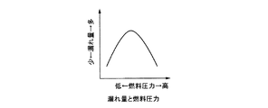
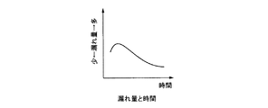
一般的に、燃料漏れ量は、燃料噴射弁51の構造により異なるが、同じ燃料噴射弁51であった場合、図2・図3に示すように、シートおよびニードルに作用する燃料圧力よって変化する。図2・図3は、燃料圧力と漏れ量、および経過時間と漏れ量の関係を、それぞれ示している。図から分かるように、燃料圧力が高い状態および低い状態では、漏れ量が少なくなっており(図2)、また、残圧によりニードルがシートに馴染むことから、時間が経過するとともに漏れ量が少なくなる傾向を示す(図3)。
That is, the in-cylinder direct injection type engine 1 that directly injects fuel into the combustion chamber 6 accumulates high-pressure fuel produced by the high-
In the high-
In the conventional system configuration of the fuel
In general, the amount of fuel leakage varies depending on the structure of the
そこで、このエンジン1の燃料噴射制御装置77は、予めエンジン1が停止した理由毎に複数のエンジン停止モードを設定し、複数のエンジン停止モードの内どのエンジン停止モードでエンジン1が停止されたかによって、デリバリパイプ49内の残圧を変化させるための燃料制御を実施している。燃料噴射制御装置77は、エンジン停止モードとして、通常停止モードとアイドルストップモードと熱害停止モードとを設定している。
運転者の意志に基づいてエンジン1を停止する通常停止モードの場合では、シャットダウンモード(停止時制御)において、高圧燃料ポンプ47のスピル弁53を制御し、低燃料圧力状態とする。すなわち、デリバリパイプ49内の残圧(燃料圧力)を低くし、燃料噴射弁51からの漏れ量を少なくする。
また、エンジン運転状態制御手段84からの指令によりエンジン1を停止するアイドルストップモードや、燃料温度が上昇し次回のエンジン再始動時に影響を与える可能性がある状態でエンジン1を停止する熱害停止モード等の、再始動が考えられる場合においては、通常停止モードとは逆に、高圧燃料ポンプ47のスピル弁53を高燃料圧力状態となるように制御し、デリバリパイプ49内の残圧(燃料圧力)を高くして、燃料噴射弁51からの漏れ量を少なくする。
このように、このエンジン1の燃料噴射制御装置46は、エンジン1の停止判定後、デリバリパイプ49内の燃料圧力を制御するものであり、エンジン停止判定を3つのモードに分け(アイドルストップモード、熱害停止モード、通常停止モード)、それぞれのモードで目標燃料圧力を設定(アイドルストップモードおよび熱害停止モードでは、目標燃料圧力を高く設定、通常停止モードでは、目標燃料圧力を低く設定)している。
Therefore, the fuel
In the normal stop mode in which the engine 1 is stopped based on the driver's will, the spill valve 53 of the high-
Further, an idle stop mode in which the engine 1 is stopped by a command from the engine operating state control means 84, or a thermal damage stop in which the engine 1 is stopped in a state where the fuel temperature rises and may affect the next engine restart. In the case where restart is possible, such as in the mode, the spill valve 53 of the high-
As described above, the fuel
次に、この実施例の作用を説明する。
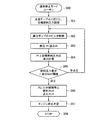
このエンジン1の燃料噴射制御装置77は、図4に示すように、エンジン停止ルーチンによって、エンジン1の停止を判断する。エンジン停止ルーチン(100)においては、イグニションスイッチがOFF(Ig.SW:OFF)されたかを判断する(101)。
この判断(101)がNOの場合は、エンジン停止ルーチン(100)のスタートに戻る(102)。この判断(101)がYESの場合は、停止モード判定ルーチンに移行する(103)。
Next, the operation of this embodiment will be described.
As shown in FIG. 4, the fuel
If this determination (101) is NO, the process returns to the start of the engine stop routine (100) (102). If this determination (101) is YES, the routine proceeds to a stop mode determination routine (103).
図5に示すように、前記停止モード判定ルーチン(200)においては、各種センサ68〜76の検出信号からエンジン回転数、吸気温、水温等のエンジン運転条件を読み込み(201)、アイドルストップモード判定条件が成立するかを判断する(202)。
この判断(202)が成立の場合は、アイドルストップモードルーチンへ移行する(203)。この判断(202)が不成立の場合は、熱害停止モード判定条件が成立するかを判断する(204)。
この判断(204)が成立の場合は、熱害停止モードルーチンへ移行する(205)。この判断(204)が不成立の場合は、通常停止モードルーチンへ移行する(206)。
このように、停止モード判定ルーチン(200)においては、エンジン運転条件による停止モードの判断、すなわちアイドルストップモード、熱害停止モード、もしくはユーザー操作による通常停止モードであるかを判断する。
As shown in FIG. 5, in the stop mode determination routine (200), engine operating conditions such as engine speed, intake air temperature, and water temperature are read from the detection signals of the
If this determination (202) is established, the routine proceeds to an idle stop mode routine (203). If this determination (202) is not satisfied, it is determined whether a thermal damage stop mode determination condition is satisfied (204).
If this determination (204) is established, the routine proceeds to a thermal damage stop mode routine (205). If this determination (204) is not established, the routine proceeds to a normal stop mode routine (206).
Thus, in the stop mode determination routine (200), it is determined whether the stop mode is determined based on the engine operating conditions, that is, whether the stop mode is the idle stop mode, the thermal damage stop mode, or the normal stop mode by the user operation.
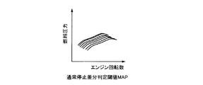
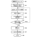
図6に示すように、前記通常停止モードルーチン(300)においては、水温テーブル(図7に示す、水温による目標燃料圧力のテーブル)に応じた目標燃料圧力を設定する(301)。通常停止モードにおける目標燃料圧力は、通常のアイドル時目標燃料圧力より低く設定することで、燃料噴射弁51からの漏れ量を低減させる。
続いて、高圧燃料ポンプ47のスピル弁53を燃料圧力制御手段85により制御し(302)、燃料圧力センサ73が検出するデリバリパイプ49内の燃料圧力Pfを読み込み(303)、燃料圧力Pfと目標燃料圧力との差分を計算し(304)、差分が差分MAP閾値(図8に示す、エンジン回転数による目標燃料圧力の差分判定閾値のMAP)未満の条件が成立するかを判断する(305)。
前記スピル弁53の制御(302)は、通常のスピル弁53のフィードバック制御とは異なり、燃料圧力Pfが目標燃料圧力より低い場合にはスピル弁53の閉制御を行い、高い場合にはスピル弁53の開制御を行い、直ちに目標燃料圧力まで燃料圧力Pfを変化させる。(通常は、目標燃料圧力が低くなるため、スピル弁53はフルオープン(全開)状態で、フィードバック制御は無し。)
前記判断(305)が不成立の場合は、前記スピル弁53の制御(302)に戻る。また、前記判断(305)が成立の場合、つまり、差分が差分MAP閾値未満となった場合は、スピル弁53の制御を停止し,燃料カットおよび点火カットを行い(306)、エンジン1の停止を判定し(307)、プログラムをストップさせる(308)。
As shown in FIG. 6, in the normal stop mode routine (300), the target fuel pressure is set according to the water temperature table (the target fuel pressure table according to the water temperature shown in FIG. 7) (301). By setting the target fuel pressure in the normal stop mode to be lower than the normal idling target fuel pressure, the amount of leakage from the
Subsequently, the spill valve 53 of the high
The control (302) of the spill valve 53 is different from the normal feedback control of the spill valve 53. When the fuel pressure Pf is lower than the target fuel pressure, the spill valve 53 is closed and when it is higher, the spill valve 53 is controlled. 53 is controlled to immediately change the fuel pressure Pf to the target fuel pressure. (Normally, since the target fuel pressure becomes low, the spill valve 53 is in a fully open state (fully open) and there is no feedback control.)
If the determination (305) is not established, the control returns to the control (302) of the spill valve 53. If the determination (305) is satisfied, that is, if the difference is less than the difference MAP threshold, the control of the spill valve 53 is stopped, fuel cut and ignition cut are performed (306), and the engine 1 is stopped. (307) and the program is stopped (308).
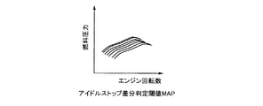
図9に示すように、前記アイドルストップモードルーチン(400)においては、目標燃料圧力定数値を読み込み、目標燃料圧力定数値に基づいて目標燃料圧力を設定する(401)。アイドルストップモードにおける目標燃料圧力は、通常のアイドル時目標燃料圧力よりも高く設定することで、燃料噴射弁51からの漏れ量を低減させる。また、エンジン運転状態制御手段84からの指令によりエンジン1を停止するアイドルストップ制御時は、エンジン1の再始動が考えられるため、デリバリパイプ49内の燃料圧力を高めに保持することで、再始動時の噴霧品質向上を図ることができる。
続いて、高圧燃料ポンプ47のスピル弁53を燃料圧力制御手段85により制御し(402)、燃料圧力センサ73が検出するデリバリパイプ49内の燃料圧力Pfを読み込み(403)、燃料圧力Pfと目標燃料圧力との差分を計算し(404)、差分が差分MAP閾値(図10に示す、エンジン回転数による目標燃料圧力の差分判定閾値のMAP)未満の条件が成立するかを判断する(405)。
前記スピル弁53の制御(402)は、通常のスピル弁53のフィードバック制御とは異なり、燃料圧力Pfが目標燃料圧力より低い場合にはスピル弁53の閉制御を行い、高い場合にはスピル弁53の開制御を行い、直ちに目標燃料圧力まで燃料圧力Pfを変化させる。(通常は、目標燃料圧力が高くなるため、スピル弁53はフルクローズ(全閉)状態で、フィードバック制御は無し。)
前記判断(405)が不成立の場合は、前記スピル弁53の制御(402)に戻る。また、前記判断(405)が成立の場合、つまり、差分が差分MAP閾値未満となった場合は、スピル弁53の制御を継続しつつ,燃料カットおよび点火カットを行い(406)、エンジン1の停止を判定し(407)、プログラムをストップさせる(408)。燃料カット実行後もエンジン1は惰性で回るため、高圧燃料ポンプ47のスピル弁53を継続制御することで、燃料圧力を作り続けることが可能である。エンジン1の惰性による燃料圧力上昇分も見込めるため、すばやくエンジン1を停止させることが可能となる。
As shown in FIG. 9, in the idle stop mode routine (400), the target fuel pressure constant value is read and the target fuel pressure is set based on the target fuel pressure constant value (401). The target fuel pressure in the idle stop mode is set higher than the normal idling target fuel pressure, thereby reducing the amount of leakage from the
Subsequently, the spill valve 53 of the high
The control (402) of the spill valve 53 is different from the normal feedback control of the spill valve 53. When the fuel pressure Pf is lower than the target fuel pressure, the spill valve 53 is closed and when it is higher, the spill valve 53 is controlled. 53 is controlled to immediately change the fuel pressure Pf to the target fuel pressure. (Normally, since the target fuel pressure becomes high, the spill valve 53 is in a fully closed state (fully closed) and there is no feedback control.)
If the determination (405) is not established, the process returns to the control (402) of the spill valve 53. Further, when the determination (405) is established, that is, when the difference is less than the difference MAP threshold, the fuel cut and the ignition cut are performed while the control of the spill valve 53 is continued (406). The stop is determined (407), and the program is stopped (408). Since the engine 1 rotates by inertia even after the fuel cut is executed, the fuel pressure can be continuously generated by continuously controlling the spill valve 53 of the high-
図11に示すように、前記熱害停止モードルーチン(500)においては、水温テーブル(図12に示す、水温による目標燃料圧力のテーブル)に応じた目標燃料圧力を設定する(501)。熱害停止モードにおける目標燃料圧力は、通常のアイドル時目標燃料圧力より高く設定することで、燃料噴射弁51からの漏れ量を低減させる。また、熱害条件下でエンジン1を停止していると、デリバリパイプ49内の燃料が暖められ、ガソリンのパーコレーションによって再始動性が悪化する。この発明では、熱害停止モードの条件下において、水温に応じて燃料圧力を高く設定することで、熱害再始動性の悪化を抑制することができる。
続いて、高圧燃料ポンプ47のスピル弁53を燃料圧力制御手段85により制御し(502)、燃料圧力センサ73が検出するデリバリパイプ49内の燃料圧力Pfを読み込み(503)、燃料圧力Pfと目標燃料圧力との差分を計算し(504)、差分が差分MAP閾値(図13に示す、エンジン回転数による目標燃料圧力の差分判定閾値のMAP)未満であるかの条件が成立するかを判断する(505)。
前記スピル弁53の制御(402)は、通常のスピル弁53のフィードバック制御とは異なり、燃料圧力Pfが目標燃料圧力より低い場合にはスピル弁53の閉制御を行い、高い場合にはスピル弁53の開制御を行い、直ちに目標燃料圧力まで燃料圧力Pfを変化させる。(通常は、目標燃料圧力が高くなるため、スピル弁53はフルクローズ(全閉)状態で、フィードバック制御は無し。)
前記判断(505)が不成立の場合は、前記スピル弁53の制御(502)に戻る。また、前記判断(505)が成立の場合、つまり、差分が差分MAP閾値未満となった場合は、スピル弁53の制御を継続しつつ,燃料カットおよび点火カットを行い(506)、エンジン1の停止を判定し(507)、プログラムをストップさせる(508)。燃料カット実行後もエンジン1は惰性で回るため、高圧燃料ポンプ47のスピル弁53を継続制御することで、燃料圧力を作り続けることが可能である。エンジン1の惰性による燃料圧力上昇分も見込めるため、すばやくエンジン1を停止させることが可能となる。
As shown in FIG. 11, in the thermal damage stop mode routine (500), the target fuel pressure is set according to the water temperature table (the target fuel pressure table based on the water temperature shown in FIG. 12) (501). The target fuel pressure in the thermal damage stop mode is set to be higher than the normal idling target fuel pressure, thereby reducing the amount of leakage from the
Subsequently, the spill valve 53 of the high
The control (402) of the spill valve 53 is different from the normal feedback control of the spill valve 53. When the fuel pressure Pf is lower than the target fuel pressure, the spill valve 53 is closed and when it is higher, the spill valve 53 is controlled. 53 is controlled to immediately change the fuel pressure Pf to the target fuel pressure. (Normally, since the target fuel pressure becomes high, the spill valve 53 is in a fully closed state (fully closed) and there is no feedback control.)
If the determination (505) is not established, the control returns to the control (502) of the spill valve 53. If the determination (505) is satisfied, that is, if the difference is less than the difference MAP threshold, the fuel cut and the ignition cut are performed while continuing the control of the spill valve 53 (506). Stop is determined (507), and the program is stopped (508). Since the engine 1 rotates by inertia even after the fuel cut is executed, the fuel pressure can be continuously generated by continuously controlling the spill valve 53 of the high-
このように、この筒内噴射式のエンジン1の燃料噴射制御装置77は、エンジン1がどのような状況下で停止されたか(複数のエンジン停止モードの内、どのエンジン停止モードで停止されたか)に応じて、停止時における目標燃料圧力の値を設定しているので、エンジン停止後の次のエンジン始動時における始動性能を落とすことなく、燃料供給系の燃料噴射弁51から燃焼室6に燃料が漏れるのを防ぐことが可能である。
これにより、このエンジン1の燃料噴射制御装置76は、始動時における排気ガス浄化性能の向上に貢献できる。
また、この筒内噴射式のエンジン1の燃料噴射制御装置77は、エンジン1が停止した理由毎に設定された複数のエンジン停止モード(通常停止モード、アイドルストップモード、熱害停止モード)に対応した、目標燃料圧力を設定できるので、精度の高いエンジン停止時の燃料圧力制御を実施可能である。
さらに、この筒内噴射式のエンジン1の燃料噴射制御装置76は、通常停止モード時には、目標燃料圧力をアイドル時燃料圧力よりも低く設定することで、燃料噴射弁51から燃焼室6内に漏れる燃料量を減少させることができ、また、アイドルストップモード時には、目標燃料圧力をアイドル時燃料圧力よりも高く設定することで、アイドルストップ後の再始動が良好に実施でき、更に、熱害停止モード時には、目標燃料圧力をエンジン水温に応じてアイドル時燃料圧力よりも高く設定することで、エンジン水温に応じた目標燃料圧力を設定できるので、再始動性能を向上させることが可能である。
なお、上述実施例においては、複数のエンジン停止モードの内、どのエンジン停止モードでエンジン1が停止されたかによって目標燃料圧力を設定したが、始動時の目標燃料圧力に関しては、以下のように設定する。
・運転者の操作による通常停止モード時では、エンジン運転条件(吸気温,水温,油温等)に応じた目標燃料圧力テーブルにて、目標燃料圧力を設定する。
・アイドルストップ条件成立時におけるアイドルストップモード時においても、エンジン運転条件(吸気温,水温,油温等)に応じたアイドルストップ時目標燃料圧力テーブルにて、目標燃料圧力を設定する。
As described above, the fuel
Thereby, the fuel
Further, the fuel
Further, the fuel
In the above-described embodiment, the target fuel pressure is set depending on which engine stop mode is stopped in the plurality of engine stop modes. However, the target fuel pressure at the start is set as follows. To do.
-In the normal stop mode by the driver's operation, the target fuel pressure is set in the target fuel pressure table corresponding to the engine operating conditions (intake air temperature, water temperature, oil temperature, etc.).
Even in the idling stop mode when the idling stop condition is satisfied, the target fuel pressure is set in the idling stop target fuel pressure table according to the engine operating conditions (intake air temperature, water temperature, oil temperature, etc.).
この発明の筒内噴射式エンジンの燃料噴射制御装置は、エンジン停止後の次のエンジン始動時における始動性能を落とすことなく、燃料供給系から燃焼室に燃料が漏れるのを防ぐことが可能であり、燃焼室内に直接燃料を噴射する燃料噴射弁を備えたエンジンに適用することができる。 The fuel injection control device for a direct injection engine according to the present invention can prevent the fuel from leaking from the fuel supply system to the combustion chamber without degrading the starting performance at the next engine starting after the engine is stopped. The present invention can be applied to an engine including a fuel injection valve that directly injects fuel into a combustion chamber.
1 エンジン(筒内噴射式エンジン)
6 燃焼室
21 吸気通路
27 排気通路
42 燃料タンク
47 高圧燃料ポンプ
48 高圧燃料供給通路
49 デリバリパイプ
50 逆止弁
51 燃料噴射弁
52 燃料戻り通路
53 スピル弁
68 スロットル開度センサ
70 吸気温センサ
71 クランク角センサ
73 燃料圧力センサ
75 水温センサ
77 燃料噴射制御装置
78 制御手段
83 燃料噴射制御手段
84 エンジン運転状態制御手段
85 燃料圧力制御手段
86 エンジン停止モード判定手段
87 エンジン停止時燃料圧力制御手段
1 engine (in-cylinder injection engine)
6
Claims (1)
前記デリバリパイプ内の燃料圧力を検出する燃料圧力検出手段を備え、
前記燃料圧力検出手段で検出された燃料圧力が、目標燃料圧力になるように制御する燃料圧力制御手段を備え、
予め前記エンジンが停止した理由毎に設定された複数のエンジン停止モードとして、運転者の意志に基づいてエンジンを停止する通常停止モードと、エンジン運転状態制御手段からの指令によりエンジンを停止するアイドルストップモードと、燃料温度が上昇し次回のエンジン再始動時に影響を与える可能性がある状態でエンジンを停止する熱害停止モードとを備え、
どのエンジン停止モードを選択し、エンジンが停止されたのかを判定するエンジン停止モード判定手段を備え、
前記エンジン停止モード判定手段で判定されたエンジン停止モードに応じて、前記燃料圧力制御手段により制御する目標燃料圧力の値を設定するエンジン停止時燃料圧力制御手段を備え、
前記通常停止モード時には、目標燃料圧力をアイドル時燃料圧力よりも低く設定し、前記アイドルストップモード時には、目標燃料圧力をアイドル時燃料圧力よりも高く設定し、前記熱害停止モード時には、目標燃料圧力をエンジン水温に応じてアイドル時燃料圧力よりも高く設定し、燃料圧力と目標燃料圧力との差分が所定未満となった時に燃料カットおよび点火カットを行い、その後にエンジンの停止の判定を行うことを特徴とする筒内噴射式エンジンの燃料噴射制御装置。 Fuel injection control for a cylinder injection engine comprising a fuel injection valve that directly injects fuel into a combustion chamber, a high-pressure fuel pump, and a delivery pipe that supplies fuel sent from the high-pressure fuel pump to the fuel injection valve In the device
A fuel pressure detecting means for detecting the fuel pressure in the delivery pipe;
Fuel pressure control means for controlling the fuel pressure detected by the fuel pressure detection means to be a target fuel pressure;
As a plurality of engine stop modes set for each reason why the engine has been stopped in advance, a normal stop mode for stopping the engine based on the driver's will and an idle stop for stopping the engine by a command from the engine operating state control means And a thermal damage stop mode that stops the engine in a state where the fuel temperature rises and may affect the next engine restart,
An engine stop mode determining means for determining which engine stop mode is selected and determining whether the engine is stopped;
Engine stop fuel pressure control means for setting a target fuel pressure value controlled by the fuel pressure control means according to the engine stop mode determined by the engine stop mode determination means ;
In the normal stop mode, the target fuel pressure is set lower than the idle fuel pressure, in the idle stop mode, the target fuel pressure is set higher than the idle fuel pressure, and in the thermal damage stop mode, the target fuel pressure is set. Is set higher than the idling fuel pressure according to the engine water temperature, fuel cut and ignition cut are performed when the difference between the fuel pressure and the target fuel pressure is less than the predetermined value, and then the engine stop is judged A fuel injection control device for an in-cylinder injection engine.
Priority Applications (1)
| Application Number | Priority Date | Filing Date | Title |
|---|---|---|---|
| JP2008299585A JP5115822B2 (en) | 2008-11-25 | 2008-11-25 | Fuel injection control device for in-cylinder injection engine |
Applications Claiming Priority (1)
| Application Number | Priority Date | Filing Date | Title |
|---|---|---|---|
| JP2008299585A JP5115822B2 (en) | 2008-11-25 | 2008-11-25 | Fuel injection control device for in-cylinder injection engine |
Publications (2)
| Publication Number | Publication Date |
|---|---|
| JP2010127092A JP2010127092A (en) | 2010-06-10 |
| JP5115822B2 true JP5115822B2 (en) | 2013-01-09 |
Family
ID=42327668
Family Applications (1)
| Application Number | Title | Priority Date | Filing Date |
|---|---|---|---|
| JP2008299585A Expired - Fee Related JP5115822B2 (en) | 2008-11-25 | 2008-11-25 | Fuel injection control device for in-cylinder injection engine |
Country Status (1)
| Country | Link |
|---|---|
| JP (1) | JP5115822B2 (en) |
Families Citing this family (2)
| Publication number | Priority date | Publication date | Assignee | Title |
|---|---|---|---|---|
| JP5991268B2 (en) * | 2013-05-28 | 2016-09-14 | 株式会社デンソー | Fuel supply device for internal combustion engine |
| JP6720996B2 (en) | 2018-04-02 | 2020-07-08 | トヨタ自動車株式会社 | Control device for hybrid vehicle |
Family Cites Families (3)
| Publication number | Priority date | Publication date | Assignee | Title |
|---|---|---|---|---|
| JP3829035B2 (en) * | 1999-11-30 | 2006-10-04 | 株式会社日立製作所 | Engine fuel pressure control device |
| JP3791298B2 (en) * | 2000-05-09 | 2006-06-28 | トヨタ自動車株式会社 | In-cylinder injection internal combustion engine controller |
| JP2004293354A (en) * | 2003-03-26 | 2004-10-21 | Mazda Motor Corp | Fuel injection control device of engine |
-
2008
- 2008-11-25 JP JP2008299585A patent/JP5115822B2/en not_active Expired - Fee Related
Also Published As
| Publication number | Publication date |
|---|---|
| JP2010127092A (en) | 2010-06-10 |
Similar Documents
| Publication | Publication Date | Title |
|---|---|---|
| US10273892B2 (en) | Fuel supply system for an internal combustion engine | |
| US7801672B2 (en) | After-stop fuel pressure control device of direct injection engine | |
| US20140251280A1 (en) | Control apparatus for internal combustion engine and control method for internal combustion engine | |
| JP6137473B2 (en) | Engine control device | |
| JP5989406B2 (en) | Fuel pressure control device | |
| JP2002174134A (en) | Engine control device | |
| US9702321B2 (en) | Fuel supply system for an internal combustion engine | |
| JP5115822B2 (en) | Fuel injection control device for in-cylinder injection engine | |
| JP2019027296A (en) | Engine system | |
| JP2013155615A (en) | Control device of internal combustion engine | |
| JP2009191650A (en) | Control device of internal combustion engine | |
| JP4470794B2 (en) | Engine start-up injection control device | |
| JP6049563B2 (en) | Engine control device | |
| JP6160816B2 (en) | Engine control device | |
| JP2010265751A (en) | Engine air fuel ratio control device | |
| JP2021173261A (en) | Engine device | |
| JP2021183836A (en) | Engine device | |
| JP2019173578A (en) | Engine control device | |
| JP2012052441A (en) | Ignition control device of internal combustion engine | |
| JP5510649B2 (en) | Air-fuel ratio control device for internal combustion engine | |
| JP5786468B2 (en) | Control device for internal combustion engine | |
| JP2007327422A (en) | Fuel injection control device of internal combustion engine | |
| JP2022012630A (en) | Engine device | |
| JP2021188511A (en) | Engine device | |
| CN117780519A (en) | Start control device for internal combustion engine |
Legal Events
| Date | Code | Title | Description |
|---|---|---|---|
| A621 | Written request for application examination |
Free format text: JAPANESE INTERMEDIATE CODE: A621 Effective date: 20110621 |
|
| A131 | Notification of reasons for refusal |
Free format text: JAPANESE INTERMEDIATE CODE: A131 Effective date: 20120425 |
|
| A977 | Report on retrieval |
Free format text: JAPANESE INTERMEDIATE CODE: A971007 Effective date: 20120427 |
|
| A521 | Written amendment |
Free format text: JAPANESE INTERMEDIATE CODE: A523 Effective date: 20120619 |
|
| TRDD | Decision of grant or rejection written | ||
| A01 | Written decision to grant a patent or to grant a registration (utility model) |
Free format text: JAPANESE INTERMEDIATE CODE: A01 Effective date: 20120920 |
|
| A01 | Written decision to grant a patent or to grant a registration (utility model) |
Free format text: JAPANESE INTERMEDIATE CODE: A01 |
|
| A61 | First payment of annual fees (during grant procedure) |
Free format text: JAPANESE INTERMEDIATE CODE: A61 Effective date: 20121003 |
|
| FPAY | Renewal fee payment (event date is renewal date of database) |
Free format text: PAYMENT UNTIL: 20151026 Year of fee payment: 3 |
|
| LAPS | Cancellation because of no payment of annual fees |