JP5114916B2 - Electrical component box - Google Patents
Electrical component box Download PDFInfo
- Publication number
- JP5114916B2 JP5114916B2 JP2006274885A JP2006274885A JP5114916B2 JP 5114916 B2 JP5114916 B2 JP 5114916B2 JP 2006274885 A JP2006274885 A JP 2006274885A JP 2006274885 A JP2006274885 A JP 2006274885A JP 5114916 B2 JP5114916 B2 JP 5114916B2
- Authority
- JP
- Japan
- Prior art keywords
- casing
- electrolytic capacitor
- substrate
- electrical component
- opening
- Prior art date
- Legal status (The legal status is an assumption and is not a legal conclusion. Google has not performed a legal analysis and makes no representation as to the accuracy of the status listed.)
- Expired - Fee Related
Links
- 239000003990 capacitor Substances 0.000 claims description 160
- 239000000758 substrate Substances 0.000 claims description 59
- 238000007789 sealing Methods 0.000 claims description 20
- 230000002093 peripheral effect Effects 0.000 claims description 18
- 230000007613 environmental effect Effects 0.000 description 11
- 238000004382 potting Methods 0.000 description 10
- 238000000034 method Methods 0.000 description 8
- 239000000463 material Substances 0.000 description 6
- 125000006850 spacer group Chemical group 0.000 description 6
- 239000000853 adhesive Substances 0.000 description 5
- 230000001070 adhesive effect Effects 0.000 description 5
- 230000000694 effects Effects 0.000 description 5
- 238000004064 recycling Methods 0.000 description 5
- 239000000428 dust Substances 0.000 description 2
- 230000017525 heat dissipation Effects 0.000 description 2
- NJPPVKZQTLUDBO-UHFFFAOYSA-N novaluron Chemical compound C1=C(Cl)C(OC(F)(F)C(OC(F)(F)F)F)=CC=C1NC(=O)NC(=O)C1=C(F)C=CC=C1F NJPPVKZQTLUDBO-UHFFFAOYSA-N 0.000 description 2
- 239000011347 resin Substances 0.000 description 2
- 229920005989 resin Polymers 0.000 description 2
- XLYOFNOQVPJJNP-UHFFFAOYSA-N water Substances O XLYOFNOQVPJJNP-UHFFFAOYSA-N 0.000 description 2
- 241000238631 Hexapoda Species 0.000 description 1
- 239000011810 insulating material Substances 0.000 description 1
- 239000002184 metal Substances 0.000 description 1
- 238000009423 ventilation Methods 0.000 description 1
Images


Landscapes
- Inverter Devices (AREA)
- Casings For Electric Apparatus (AREA)
Description
この発明は、電装品箱に関し、詳しくは、空気調和機の室外機等に使用される電装品箱に関する。 The present invention relates to an electrical component box, and more particularly to an electrical component box used for an outdoor unit or the like of an air conditioner.
従来、電装品箱としては、空気調和機の室外機に用いられたものがある(例えば、特開2006−194584号公報(特許文献1)参照)。この電装品箱では、インバータ装置等が収納されており、放熱性をよくするためにケーシングに通気開口部を設けている。 Conventionally, as an electrical component box, there is one used for an outdoor unit of an air conditioner (see, for example, JP-A-2006-194484 (Patent Document 1)). In this electrical component box, an inverter device and the like are housed, and a ventilation opening is provided in the casing in order to improve heat dissipation.
このような空気調和機の室外機に用いられる電装品箱において、耐環境性を向上するために電装品箱を密閉構造にする要望が高まっている。しかしながら、そのような密閉構造の電装品箱では、電装品箱内の温度が上昇するため、インバータ装置等に用いられる電解コンデンサの寿命が短くなるという問題がある。
そこで、この発明の課題は、密閉構造により耐環境性能を高めつつ、簡単な構造で電解コンデンサの長寿命化が図れる電装品箱を提供することにある。 SUMMARY OF THE INVENTION An object of the present invention is to provide an electrical component box capable of extending the life of an electrolytic capacitor with a simple structure while improving environmental resistance performance by a sealed structure.
上記課題を解決するため、この発明の電装品箱では、
密閉構造のケーシングと、
上記ケーシング内に配置された基板と、
上記基板に実装され、上記ケーシングに固定されていない電解コンデンサと
を備え、
上記ケーシングに設けられた開口部から上記電解コンデンサの一部が外部に露出し、
上記ケーシングの上記開口部の内周と上記電解コンデンサの外周との隙間を密閉する弾性シール部材を備え、
上記ケーシングに設けられ、上記開口部の周縁部から上記基板側に向かって延びる延伸筒部を備え、
上記弾性シール部材は、上記電解コンデンサに外嵌され、上記延伸筒部の先端と上記基板との間および上記延伸筒部の先端側と上記電解コンデンサの外周との間を密閉する。
In order to solve the above problem, in the electrical component box of the present invention ,
A sealed casing;
A substrate disposed in the casing;
An electrolytic capacitor mounted on the substrate and not fixed to the casing;
With
A part of the electrolytic capacitor is exposed to the outside through an opening provided in the casing,
An elastic seal member for sealing a gap between the inner periphery of the opening of the casing and the outer periphery of the electrolytic capacitor;
Provided in the casing, and provided with a stretched cylindrical portion extending from the peripheral edge of the opening toward the substrate,
The elastic seal member is externally fitted to the electrolytic capacitor, and seals between the tip of the extending cylinder part and the substrate and between the tip side of the extending cylinder part and the outer periphery of the electrolytic capacitor.
上記構成の電装品箱によれば、基板に実装された電解コンデンサの一部をケーシングに設けた開口部から露出させて、ケーシングの開口部の内周と電解コンデンサの外周との隙間を密閉することによって、ケーシングの内部温度よりも低温のケーシングの外部に電解コンデンサの一部を曝露して放熱する。したがって、密閉構造のケーシングにより耐環境性能を高めつつ、簡単な構成で電解コンデンサの寿命を延ばすことができる。また、電解コンデンサの寿命を露出構造にする前と同じに想定した場合は、耐熱温度の低い電解コンデンサが使用でき、コストを低減できる。また、上記ケーシングの開口部の周縁部から基板側に向かって延びる延伸筒部と基板との間、および、延伸筒部の先端側と電解コンデンサの外周との間を、電解コンデンサに外嵌された弾性シール部材により密閉することによって、電解コンデンサを露出させるケーシングの開口部を安価な方法でシールするので、コストを上げずに電解コンデンサの寿命を延ばすことができる。また、弾性シール部材を基板に接するように電解コンデンサの下部に配置することにより、ケーシングの延伸筒部の先端が弾性シール部材に押し付けられたとき、弾性シール部材が基板側にずれるのを防止でき、弾性シール部材によるシール性を向上できる。 According to the electrical component box having the above configuration, a part of the electrolytic capacitor mounted on the substrate is exposed from the opening provided in the casing, and the gap between the inner periphery of the opening of the casing and the outer periphery of the electrolytic capacitor is sealed. As a result, a part of the electrolytic capacitor is exposed to the outside of the casing at a temperature lower than the internal temperature of the casing to dissipate heat. Therefore, it is possible to extend the life of the electrolytic capacitor with a simple configuration while improving the environmental performance by the sealed casing. In addition, when the life of the electrolytic capacitor is assumed to be the same as that before the exposed structure, an electrolytic capacitor having a low heat-resistant temperature can be used, thereby reducing the cost. Further , the electrolytic capacitor is externally fitted between the extending cylindrical portion extending from the peripheral portion of the opening of the casing toward the substrate side and the substrate, and between the distal end side of the extending cylindrical portion and the outer periphery of the electrolytic capacitor. By sealing with an elastic seal member, the opening of the casing exposing the electrolytic capacitor is sealed by an inexpensive method, so that the lifetime of the electrolytic capacitor can be extended without increasing costs. In addition, by disposing the elastic seal member in the lower part of the electrolytic capacitor so as to contact the substrate, it is possible to prevent the elastic seal member from shifting to the substrate side when the tip of the extending cylindrical portion of the casing is pressed against the elastic seal member. The sealing performance by the elastic seal member can be improved.
また、この発明の電装品箱では、
密閉構造のケーシングと、
上記ケーシング内に配置された基板と、
上記基板に実装され、上記ケーシングに固定されていない電解コンデンサと
を備え、
上記ケーシングに設けられた開口部から上記電解コンデンサの一部が外部に露出し、
上記ケーシングの上記開口部の内周と上記電解コンデンサの外周との隙間を密閉する弾性シール部材を備え、
上記ケーシングに設けられ、上記開口部の周縁部から上記基板側に向かって延びる第1延伸筒部と、
上記電解コンデンサに外嵌された環状の上記弾性シール部材の外周部から上記ケーシングに向かって延び、かつ、上記ケーシング側の上記第1延伸筒部の外側を囲うように設けられた第2延伸筒部と
を備え、
上記第1延伸筒部と上記第2延伸筒部によってラビリンスを形成している。
In the electrical component box of the present invention ,
A sealed casing;
A substrate disposed in the casing;
An electrolytic capacitor mounted on the substrate and not fixed to the casing;
With
A part of the electrolytic capacitor is exposed to the outside through an opening provided in the casing,
An elastic seal member for sealing a gap between the inner periphery of the opening of the casing and the outer periphery of the electrolytic capacitor;
A first extending cylinder provided in the casing and extending from a peripheral edge of the opening toward the substrate;
A second extending cylinder that extends from the outer peripheral portion of the annular elastic seal member fitted around the electrolytic capacitor toward the casing, and is provided so as to surround the outside of the first extending cylinder portion on the casing side. With
A labyrinth is formed by the first extending cylinder part and the second extending cylinder part.
上記構成の電装品箱によれば、基板に実装された電解コンデンサの一部をケーシングに設けた開口部から露出させて、ケーシングの開口部の内周と電解コンデンサの外周との隙間を密閉することによって、ケーシングの内部温度よりも低温のケーシングの外部に電解コンデンサの一部を曝露して放熱する。したがって、密閉構造のケーシングにより耐環境性能を高めつつ、簡単な構成で電解コンデンサの寿命を延ばすことができる。また、電解コンデンサの寿命を露出構造にする前と同じに想定した場合は、耐熱温度の低い電解コンデンサが使用でき、コストを低減できる。また、上記ケーシングの開口部の周縁部から基板側に向かって設けられ第1延伸筒部と、電解コンデンサに外嵌された環状の弾性部材の外周部からケーシングに向かって延び、かつ、ケーシング側の第1延伸筒部の外側を囲うように設けられた第2延伸筒部とによって、ラビリンスを形成することによって、電解コンデンサを露出させるケーシングの開口部を安価な方法でシールするので、コストを上げずに電解コンデンサの寿命を延ばすことができる。また、接着剤やポッティング材を使用しないため、リサイクルが容易にできる。 According to the electrical component box having the above configuration, a part of the electrolytic capacitor mounted on the substrate is exposed from the opening provided in the casing, and the gap between the inner periphery of the opening of the casing and the outer periphery of the electrolytic capacitor is sealed. As a result, a part of the electrolytic capacitor is exposed to the outside of the casing at a temperature lower than the internal temperature of the casing to dissipate heat. Therefore, it is possible to extend the life of the electrolytic capacitor with a simple configuration while improving the environmental performance by the sealed casing. In addition, when the life of the electrolytic capacitor is assumed to be the same as that before the exposed structure, an electrolytic capacitor having a low heat-resistant temperature can be used, thereby reducing the cost. Further , the first extending cylinder portion provided from the peripheral edge of the opening of the casing toward the substrate side, and extending from the outer peripheral portion of the annular elastic member externally fitted to the electrolytic capacitor toward the casing, and on the casing side Since the labyrinth is formed by the second extending cylinder portion provided so as to surround the outside of the first extending cylinder portion, the opening of the casing exposing the electrolytic capacitor is sealed by an inexpensive method. The life of the electrolytic capacitor can be extended without raising it. In addition, since no adhesive or potting material is used, recycling is easy.
以上より明らかなように、この発明の電装品箱によれば、耐環境性の高い密閉構造において、簡単な構造で電解コンデンサの長寿命化が図れる電装品箱を実現することができる。 As is clear from the above, according to the electrical component box of the present invention, an electrical component box that can extend the life of an electrolytic capacitor with a simple structure can be realized in a sealed structure with high environmental resistance.
また、上記ケーシングの開口部の周縁部から基板側に向かって延びた延伸筒部の先端と基板との間、および、延伸筒部の先端側と電解コンデンサの外周との間を、電解コンデンサに外嵌された弾性シール部材により密閉することによって、電解コンデンサを露出させるケーシングの開口部を安価な方法でシールするので、コストを上げずに電解コンデンサの寿命を延ばすことができる。また、弾性シール部材を基板に接するように電解コンデンサの下部に配置することにより、ケーシングの延伸筒部の先端が弾性シール部材に押し付けられたとき、弾性シール部材が基板側にずれるのを防止でき、弾性シール部材によるシール性を向上できる。 Also, between the tip and the substrate of the stretch tube portion extending from the perimeter of the opening of the upper Symbol casing toward the substrate side, and, between the outer periphery of the distal end side and the electrolytic capacitor of the stretched tube portion, electrolytic capacitor Since the opening of the casing exposing the electrolytic capacitor is sealed by an inexpensive method by sealing with the elastic seal member fitted on the outer surface of the capacitor, the life of the electrolytic capacitor can be extended without increasing the cost. In addition, by disposing the elastic seal member in the lower part of the electrolytic capacitor so as to contact the substrate, it is possible to prevent the elastic seal member from shifting to the substrate side when the tip of the extending cylindrical portion of the casing is pressed against the elastic seal member. The sealing performance by the elastic seal member can be improved.
また、この発明の電装品箱によれば、耐環境性の高い密閉構造において、簡単な構造で電解コンデンサの長寿命化が図れる電装品箱を実現することができる。
また、上記ケーシングの開口部の周縁部から基板側に向かって設けられた第1延伸筒部と、電解コンデンサに外嵌された環状の弾性部材の外周部からケーシングに向かって延び、かつ、ケーシング側の第1延伸筒部の外側を囲うように設けられた第2延伸筒部とによって、ラビリンスを形成することによって、電解コンデンサを露出させるケーシングの開口部を安価な方法でシールするので、コストを上げずに電解コンデンサの寿命を延ばすことができる。また、接着剤やポッティング材を使用しないため、リサイクルが容易にできる。
Further, according to the electrical component box of the present invention , it is possible to realize an electrical component box capable of extending the life of the electrolytic capacitor with a simple structure in a highly environmentally sealed structure.
A first extending cylinder provided from the peripheral edge of the opening of the casing toward the substrate; and an outer peripheral portion of an annular elastic member fitted on the electrolytic capacitor; Since the labyrinth is formed by the second extending cylinder portion provided so as to surround the outside of the first extending cylinder portion on the side, the opening of the casing exposing the electrolytic capacitor is sealed by an inexpensive method. The lifetime of the electrolytic capacitor can be extended without increasing the value. In addition, since no adhesive or potting material is used, recycling is easy.
以下、この発明の電装品箱を図示の実施の形態により詳細に説明する。 Hereinafter, the electrical component box of the present invention will be described in detail with reference to the illustrated embodiments.
〔第1実施形態〕
図1はこの発明の第1実施形態の電装品箱の要部の断面図を示している。また、図8はこの第1実施形態の電装品箱1の斜視図を示しており、この電装品箱1は、金属製の箱形状のケーシング11と、上記ケーシング11内に電子部品(電解コンデンサ13を含む)が実装された基板12とを備えている。このケーシング11は、基板12が内部に取り付けられ、上側が開口する底部11Aと、上記底部11Aの上側開口を蓋する蓋部11Bとを備えた密閉構造をしている。
[First Embodiment]
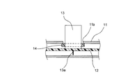
FIG. 1 shows a cross-sectional view of an essential part of an electrical component box according to the first embodiment of the present invention. FIG. 8 is a perspective view of the electrical component box 1 of the first embodiment. The electrical component box 1 includes a metal box-
図1に示すように、ケーシング11内に配置された基板12に、円柱形状の電解コンデンサ13が実装されている。上記電解コンデンサ13の下端側から下方に伸びた2つのリード端子13a(図1では1つのみを示す)が、基板12に設けられたスルーホール(図示せず)内に挿入され、ハンダ付けされている。また、上記ケーシング11に円形の開口部11aが設けられている。この円形の開口部11aの直径は、電解コンデンサ13の直径より大きく、電解コンデンサ13の外周と開口部11aの内周との隙間は、略2mmとしている。そうして、上記電解コンデンサ13の一部を、ケーシング11に設けられた円形の開口部11aから突出して外部に露出させている。
As shown in FIG. 1, a cylindrical
上記電解コンデンサ13のカシメ部の外周に、環状の弾性シール部材14を予め取り付けている。この弾性シール部材14の外周は、ケーシング11に設けられた円形の開口部11aよりも大きくしている。それによって、弾性シール部材14の基板12側と反対の端面の外周部を、ケーシング11の円形の開口部11aの周縁部に密着させて、電解コンデンサ13とケーシング11との間を密閉している。
An annular
上記ケーシングに設けた開口部の径サイズは、ケーシングの歪を考慮して電解コンデンサの直径より大きくする(ケーシング自体のサイズ、形状、材質や開口部の位置により異なるが、空気調和機のケーシングであれば、通常約2mm程度の隙間を設けるのが妥当である)。 The diameter of the opening provided in the casing is made larger than the diameter of the electrolytic capacitor in consideration of the distortion of the casing (it varies depending on the size, shape, material, and position of the opening of the casing itself, but in the casing of the air conditioner. If so, it is usually appropriate to provide a gap of about 2 mm).
上記構成の電装品箱によれば、電解コンデンサ13の一部をケーシング11から露出させて、ケーシング11の内部温度より低温のケーシング11の外部に曝露することにより、電解コンデンサ13の温度上昇が抑制されるので、密閉構造により耐環境性能を高めつつ、電解コンデンサ13の寿命を延ばすことができる。または、コンデンサの寿命を露出構造にする前と同じに寿命に想定した場合は、温度グレードの低い電解コンデンサ13を用いることにより、低コスト化が図れる。
According to the electrical component box having the above configuration, a part of the
上記電解コンデンサ13を露出させるケーシング11の開口部11aを安価な方法でシールし、ケーシング11を密閉化することにより、耐環境性能および信頼性を向上できる。
By sealing the
また、ケーシングの密閉化に接着剤やポッティング材を使用しないため、リサイクルが容易にできる。 Further, since no adhesive or potting material is used for sealing the casing, recycling can be facilitated.
上記第1実施形態の電装品箱1において、弾性シール部材14に熱伝導率の高い絶縁材料を用いることによって、電解コンデンサ13の熱が弾性シール部材14を介してケーシング11に伝わるので、電解コンデンサ13の放熱がよくなり、寿命をさらに向上できる。
In the electrical component box 1 of the first embodiment, by using an insulating material having high thermal conductivity for the
上記第1実施形態の電装品箱1では、弾性シール部材14をケーシング11内部の電解コンデンサ13の部分に外嵌したが、弾性シール部材をケーシング外部の電解コンデンサの部分に外嵌してもよい。
In the electrical component box 1 of the first embodiment, the
〔第2実施形態〕
図2はこの発明の第2実施形態の電装品箱の要部の断面図を示している。なお、この第2実施形態の電装品箱は、シール構造を除いて第1実施形態の図8に示す電装品箱と同様の構成をしている。
[Second Embodiment]
FIG. 2 shows a cross-sectional view of an essential part of an electrical component box according to a second embodiment of the present invention. The electrical component box of the second embodiment has the same configuration as the electrical component box shown in FIG. 8 of the first embodiment except for the seal structure.
図2に示すように、ケーシング21内に配置された基板22に、円柱形状の電解コンデンサ23が円板形状のスペーサ24を介して実装されている。上記スペーサ24は、電解コンデンサ23の外径よりも大きい。上記電解コンデンサ23の下端側から下方に伸びた2つのリード端子23a(図2では1つのみを示す)が、スペーサ24に設けられた穴(図示せず)を介して基板22のスルーホール(図示せず)内に挿入され、ハンダ付けされている。また、上記ケーシング21に設けられた円形の開口部21aが設けられている。この円形の開口部21aの直径は、電解コンデンサ23の直径より大きく、電解コンデンサ23の外周と開口部21aの内周との隙間は、略2mmとしている。そうして、上記電解コンデンサ23の一部を、ケーシング21に設けられた円形の開口部21aから突出して外部に露出させている。
As shown in FIG. 2, a columnar
上記電解コンデンサ23の下部のスペーサ24の外周部上かつ電解コンデンサ23の外周に、環状の弾性シール部材25を取り付け、ケーシング21を弾性シール部材25に押し付ける。これにより、上記基板22と電解コンデンサ23との間に設けられたスペーサ24の外周部とケーシング21との間を、電解コンデンサ23に外嵌された弾性シール部材25により密閉する。
An annular
上記構成の電装品箱は、第1実施形態の電装品箱と同様の効果を有する。また、スペーサ24を弾性シール部材25と基板22との間に配置することにより、ケーシング21が弾性シール部材25に押し付けられたとき、弾性シール部材25が下方向にずれることを防止でき、弾性シール部材25によるシール性が向上する。
The electrical component box having the above configuration has the same effect as the electrical component box of the first embodiment. Further, by disposing the
〔第3実施形態〕
図3はこの発明の第3実施形態の電装品箱の要部の断面図を示している。なお、この第3実施形態の電装品箱は、シール構造を除いて第1実施形態の図8に示す電装品箱と同様の構成をしている。
[Third Embodiment]
FIG. 3 shows a cross-sectional view of an essential part of an electrical component box according to a third embodiment of the present invention. The electrical component box of the third embodiment has the same configuration as the electrical component box shown in FIG. 8 of the first embodiment except for the seal structure.
図3に示すように、ケーシング31内に配置された基板32に、円柱形状の電解コンデンサ33が実装されている。上記電解コンデンサ33の下端側から下方に伸びた2つのリード端子33a(図3では1つのみを示す)が、基板32に設けられたスルーホール(図示せず)内に挿入され、ハンダ付けされている。また、上記ケーシング31に円形の開口部31aが設けられている。この円形の開口部31aの直径は、電解コンデンサ33の直径より大きく、電解コンデンサ33の外周と開口部31aの内周との隙間は、略2mmとしている。そうして、上記電解コンデンサ33の一部を、ケーシング31に設けられた円形の開口部31aから突出して外部に露出させている。
As shown in FIG. 3, a cylindrical
上記電解コンデンサ33の外周に、基板32に下端面が接するように、環状の弾性シール部材35を予め取り付けている。この弾性シール部材35の外周は、ケーシング31に設けられた円形の開口部31aよりも大きくしている。
An annular
上記ケーシング31の開口部31aから電解コンデンサ33の外周に沿って、基板32の方向へ延伸した円筒形状の延伸筒部34を設けている。この延伸筒部34の先端を、電解コンデンサ33の下部に取り付けた弾性シール部材35に押し付ける。これによって、上記ケーシング31の開口部31aの周縁部から基板32側に向かって延びる延伸筒部34と基板32との間、および、延伸筒部34の先端側と電解コンデンサ33の外周との間を、電解コンデンサ33に外嵌された弾性シール部材35により密閉する。
A cylindrical extending tube portion 34 extending in the direction of the
上記構成の電装品箱は、第1実施形態の電装品箱と同様の効果を有する。また、弾性シール部材35を基板32に接するように電解コンデンサ33の下部に配置したことにより、ケーシング31が弾性シール部材35に押し付けられたとき、弾性シール部材35が下方向にずれることを防止でき、弾性シール部材35によるシール性が向上する。
The electrical component box having the above configuration has the same effect as the electrical component box of the first embodiment. Further, since the
〔第4実施形態〕
図4はこの発明の第4実施形態の電装品箱の要部の断面図を示している。なお、この第4実施形態の電装品箱は、シール構造を除いて第1実施形態の図8に示す電装品箱と同様の構成をしている。
[Fourth Embodiment]
FIG. 4 shows a cross-sectional view of an essential part of an electrical component box according to a fourth embodiment of the present invention. The electrical component box of the fourth embodiment has the same configuration as the electrical component box shown in FIG. 8 of the first embodiment except for the seal structure.
図4に示すように、ケーシング41内に配置された基板42に、円柱形状の電解コンデンサ43が実装されている。上記電解コンデンサ43の下端側から下方に伸びた2つのリード端子43a(図4では1つのみを示す)が、基板42に設けられたスルーホール(図示せず)内に挿入され、ハンダ付けされている。また、上記ケーシング41に円形の開口部41aが設けられている。この円形の開口部41aの直径は、電解コンデンサ43の直径より大きく、電解コンデンサ33の外周と開口部41aの内周との隙間は、略2mmとしている。そうして、上記電解コンデンサ43の一部を、ケーシング41に設けられた円形の開口部41aから突出して外部に露出させている。
As shown in FIG. 4, a cylindrical
そして、上記ケーシング41に設けた開口部41aにグロメット形状の弾性シール部材45を予め取り付け、この弾性シール部材45内に電解コンデンサ43を挿入することにより、ケーシング41の密閉を行う。
A grommet-shaped
上記構成の電装品箱によれば、電解コンデンサ43の一部をケーシング41から露出させて、ケーシング41の内部温度より低温のケーシング41の外部に曝露することにより、電解コンデンサ43の温度上昇が抑制されるので、密閉構造により耐環境性能を高めつつ、電解コンデンサ43の寿命を延ばすことができる。または、コンデンサの寿命を露出構造にする前と同じに寿命に想定した場合は、温度グレードの低い電解コンデンサを用いることにより低コスト化を図ることができる。
According to the electrical component box configured as described above, a part of the
また、電解コンデンサ43を露出させるためのケーシング41の開口部41aを安価な方法でシールし、ケーシング41を密閉化することにより、耐環境性能および信頼性を向上できる。
Further, by sealing the
また、ケーシング41と電解コンデンサ43との間に弾性体(弾性シール部材45)が介在するため、ケーシング41に歪が発生した場合においても、電解コンデンサ43にかかる応力を吸収し、電解コンデンサ43を傷つけることはない。
In addition, since an elastic body (elastic sealing member 45) is interposed between the
また、接着剤やポッティング材を使用しないため、リサイクルが容易にできる。 In addition, since no adhesive or potting material is used, recycling is easy.
上記ケーシング43の開口部41aに取り付けたときの弾性シール部材45の内径は、電解コンデンサ43を挿入し密閉化するために、挿入する電解コンデンサ43の外形よりも少し小さいサイズとする。
The inner diameter of the
〔第5実施形態〕
図5はこの発明の第5実施形態の電装品箱の要部の断面図を示している。なお、この第5実施形態の電装品箱は、弾性シール部材を除いて第4実施形態の電装品箱と同様の構成をしている。
[Fifth Embodiment]
FIG. 5 shows a cross-sectional view of an essential part of an electrical component box according to a fifth embodiment of the present invention. The electrical component box of the fifth embodiment has the same configuration as the electrical component box of the fourth embodiment except for the elastic seal member.
図5に示すように、ケーシング51内に配置された基板52に、円柱形状の電解コンデンサ53が実装されている。上記電解コンデンサ53の下端側から下方に伸びた2つのリード端子53a(図5では1つのみを示す)が、基板52に設けられたスルーホール(図示せず)内に挿入され、ハンダ付けされている。また、上記ケーシング51に円形の開口部51aが設けられている。この円形の開口部51aの直径は、電解コンデンサ53の直径より大きく、電解コンデンサ33の外周と開口部51aの内周との隙間は、略2mmとしている。そうして、上記電解コンデンサ43の一部を、ケーシング51に設けられた円形の開口部51aから突出して外部に露出させている。
As shown in FIG. 5, a cylindrical
そして、上記ケーシング51に設けた開口部51aにグロメット形状の弾性シール部材54を予め取り付け、この弾性シール部材54内に電解コンデンサ43を挿入することにより、ケーシング41の密閉を行う。
A grommet-shaped
上記グロメット状の弾性シール部材54は、環状の基部54aと、その環状の基部54aの内周部に全周に亘ってかつ内側に向かって設けられた2つの環状凸部54bとを有する。この弾性シール部材54の環状凸部54bと電解コンデンサ53の外周面が密着することにより、ケーシング51を密閉化している。
The grommet-like
上記構成の電装品箱は、第4実施形態の電装品箱と同様の効果を有すると共に、弾性シール部材54の環状凸部54bがある程度柔軟であるため、電解コンデンサ53の抜き差しを容易に行うことができる。
The electrical component box having the above configuration has the same effect as the electrical component box of the fourth embodiment, and the annular
なお、上記第5実施形態の電装品箱では、グロメット状の弾性シール部材54の内周の環状凸部54bを2つとしたが、環状凸部は1つでもよいし、3以上であってもよい。
In the electrical component box of the fifth embodiment, the number of the
〔第6実施形態〕
図6はこの発明の第6実施形態の電装品箱の要部の断面図を示している。なお、この第6実施形態の電装品箱は、シール構造を除いて第1実施形態の図8に示す電装品箱と同様の構成をしている。
[Sixth Embodiment]
FIG. 6 shows a sectional view of an essential part of an electrical component box according to a sixth embodiment of the present invention. The electrical component box of the sixth embodiment has the same configuration as the electrical component box shown in FIG. 8 of the first embodiment except for the seal structure.
図6に示すように、ケーシング61内に配置された基板62に、円柱形状の電解コンデンサ63が実装されている。上記電解コンデンサ63の下端側から下方に伸びた2つのリード端子63a(図6では1つのみを示す)が、基板62に設けられたスルーホール(図示せず)内に挿入され、ハンダ付けされている。また、上記ケーシング61に円形の開口部61aが設けられている。この円形の開口部61aの直径は、電解コンデンサ63の直径より大きく、電解コンデンサ63の外周と開口部31aの内周との隙間は、略2mmとしている。そうして、上記電解コンデンサ63の一部を、ケーシング61に設けられた円形の開口部61aから突出して外部に露出させている。
As shown in FIG. 6, a cylindrical
上記ケーシング61の開口部61aの周縁部から電解コンデンサ63の外周に沿って基板62の方向に延びた円筒形状の第1延伸筒部64を設けている。
A cylindrical first extending
上記電解コンデンサ63の外周に、環状の弾性シール部材65を予め取り付けている。この弾性シール部材65は、ドーナツ形状の基部65aと、その基部65aの外周部から上方に向かって延びた円筒形状の第2延伸筒部65bとを有している。上記弾性シール部材65の第2延伸筒部65bの内径を、ケーシング61の第1延伸筒部64の外径よりも大きくして、第2延伸筒部65bが第1延伸筒部64の外側を囲うようにしている。
An annular
また、電解コンデンサ63の一部をケーシング61から露出させて、ケーシング61の内部温度より低温のケーシング61の外部に曝露することにより、電解コンデンサ63の温度上昇が抑制され、電解コンデンサ63の寿命を延ばすことができる。または、コンデンサの寿命を露出構造にする前と同じに寿命に想定した場合は、温度グレードの低い電解コンデンサを用いることにより低コスト化を図ることができる。
Further, by exposing a part of the
また、電解コンデンサ63を露出させるケーシング61を、安価な方法で粉塵、水滴等の入りにくい構造とすることにより、耐環境性能および信頼性を向上できる。
Further, the
また、接着剤やポッティング材を使用しないため、リサイクルが容易にできる。 In addition, since no adhesive or potting material is used, recycling is easy.
上記構成の電装品箱は、第1実施形態の電装品箱と同様の効果を有する。また、ケーシング61に電解コンデンサ63より一回り大きい下向き筒状の開口部61aを設け、ケーシング61の開口部61aとは逆方向の筒状の形状を持つ台座(弾性シール部材65の第2延伸筒部65b)を電解コンデンサ63に取り付け、台座の内径がケーシング61の開口部61aの外径より大きくすることにより、電解コンデンサ63の露出部にラビリンス構造を設けて、粉塵、水滴、虫等の入りにくい構造としている。
The electrical component box having the above configuration has the same effect as the electrical component box of the first embodiment. Further, the
〔第7実施形態〕
図7はこの発明の第7実施形態の電装品箱の要部の断面図を示している。なお、この第7実施形態の電装品箱は、シール構造を除いて第1実施形態の図8に示す電装品箱と同様の構成をしている。
[Seventh Embodiment]
FIG. 7 shows a cross-sectional view of an essential part of an electrical component box according to the seventh embodiment of the present invention. The electrical component box of the seventh embodiment has the same configuration as the electrical component box shown in FIG. 8 of the first embodiment except for the seal structure.
図7に示すように、ケーシング71内に配置された基板72に、円柱形状の電解コンデンサ73が実装されている。上記電解コンデンサ73の下端側から下方に伸びた2つのリード端子73a(図7では1つのみを示す)が、基板72に設けられたスルーホール(図示せず)内に挿入され、ハンダ付けされている。また、上記ケーシング71に円形の開口部71aが設けられている。この円形の開口部71aの直径は、電解コンデンサ73の直径より大きく、電解コンデンサ73の外周と開口部71aの内周との隙間は、略2mmとしている。そうして、上記電解コンデンサ73の一部を、ケーシング71に設けられた円形の開口部71aから突出して外部に露出させている。
As shown in FIG. 7, a columnar
上記ケーシング71の開口部71aから電解コンデンサ73の外周に沿って基板72の方向に延びた円筒形状の延伸筒部74を設けている。この延伸筒部74の先端を基板72表面に押し付ける。
A cylindrical extending
そして、ケーシング71と電解コンデンサ73との間に、少なくとも基板72の表面が覆われ、かつ電解コンデンサ73の下端側の一部が埋没する程度まで、弾性のある樹脂等を充填してシール部材の一例としてのポッティング部75を形成する。なお、ポッティング部75は、電解コンデンサ73のリード部近傍が埋没する程度でもよい。
Then, between the
上記構成の電装品箱は、第1実施形態の電装品箱と同様の効果を有する。また、電解コンデンサ73の一部をケーシング71から露出させて、ケーシング71の内部温度より低温のケーシング71の外部に曝露することにより、電解コンデンサ73の温度上昇が抑制され、電解コンデンサ73の寿命を延ばすことができる。または、コンデンサの寿命を露出構造にする前と同じに寿命に想定した場合は、温度グレードの低い電解コンデンサを用いることにより低コスト化を図ることができる。
The electrical component box having the above configuration has the same effect as the electrical component box of the first embodiment. Further, by exposing a part of the
また、電解コンデンサ73を露出させるケーシング71の開口部71aを安価な方法でシールし、ケーシング71を略密閉化することにより、耐環境性能および信頼性を向上できる。
Further, by sealing the
また、弾性を有する樹脂等からなるポッティング部75がケーシング71と電解コンデンサ73との間に介在するため、ケーシング71の歪が発生した場合においても、電解コンデンサ73にかかる応力を吸収し、電解コンデンサ73を傷つけることはない。
また、電解コンデンサ73が、ポッティング部75を介してケーシング71および基板72と接触することにより、電解コンデンサ73からケーシング71および基板72への伝熱性能を向上する。
Further, since the
Further, the
上記第7実施形態では、ケーシング71の円筒形状の延伸筒部74の先端を基板72表面に押し付けたが、延伸筒部の先端を基板に近接させてもよい。その場合は、延伸筒部の先端と基板との間から漏れ出さない程度の粘度を有するシール部材を延伸筒部内に充填する。
In the seventh embodiment, the tip of the cylindrical extending
上記第1〜第7実施形態では、ケーシング11,21,31,41,51,61,71内に配置された基板12,22,32,42,52,62,72に電解コンデンサ13,23,33,43,53,63,73が実装された電装品箱について説明したが、基板に実装されるコンデンサは、電解コンデンサに限らず、温度上昇により寿命が劣化するような他のコンデンサであってもよい。また、コンデンサの形状は、円柱形状に限らず、コンデンサの形状に合わせてケーシングの開口部も相似形状とするのが望ましい。
In the first to seventh embodiments, the
また、上記第1〜第7実施形態では、底部11Aと蓋部11Bからなるケーシング11を備えた電装品箱について説明したが、ケーシングはこれに限らず、他の形態のケーシングであってもよい。
Moreover, in the said 1st-7th embodiment, although the electrical component box provided with the
また、上記第1〜第7実施形態のシール構造に限らず、ケーシングに設けられた開口部と、その開口部から一部が突出するコンデンサとの間を密閉する他のシール構造を用いてもよい。 In addition to the seal structure of the first to seventh embodiments, other seal structures that seal between the opening provided in the casing and the capacitor partially protruding from the opening may be used. Good.
11,21,31,41,51,61,71…ケーシング
11a,21a,31a,41a,51a,61a,71a…開口部
12,22,32,42,52,62,72…基板
13,23,33,43,53,63,73…電解コンデンサ
14,25,35,45,54,65…弾性シール部材
24…スペーサ
34,64,65b,74…延伸筒部
64…第1延伸筒部
65b…第2延伸筒部
75…ポッティング部
11, 21, 31, 41, 51, 61, 71 ...
Claims (2)
上記ケーシング(31)内に配置された基板(32)と、
上記基板(32)に実装され、上記ケーシング(31)に固定されていない電解コンデンサ(33)と
を備え、
上記ケーシング(31)に設けられた開口部(31a)から上記電解コンデンサ(33)の一部が外部に露出し、
上記ケーシング(31)の上記開口部(31a)の内周と上記電解コンデンサ(33)の外周との隙間を密閉する弾性シール部材(35)を備え、
上記ケーシング(31)に設けられ、上記開口部(31a)の周縁部から上記基板(32)側に向かって延びる延伸筒部(34)を備え、
上記弾性シール部材(35)は、上記電解コンデンサ(33)に外嵌され、上記延伸筒部(34)の先端と上記基板(32)との間および上記延伸筒部(34)の先端側と上記電解コンデンサ(33)の外周との間を密閉することを特徴とする電装品箱。 A sealed casing (31);
A substrate (32) disposed in the casing (31);
An electrolytic capacitor (33) mounted on the substrate (32) and not fixed to the casing (31);
With
A portion of the electrolytic capacitor (33) is exposed to the outside through an opening (31a) provided in the casing (31),
An elastic seal member (35) for sealing a gap between the inner periphery of the opening (31a) of the casing (31) and the outer periphery of the electrolytic capacitor (33);
Provided in the casing (31), comprising an extending cylinder part (34) extending from the peripheral part of the opening (31a) toward the substrate (32) side,
The elastic seal member (35) is externally fitted to the electrolytic capacitor (33), and is provided between the tip of the stretched cylinder portion (34) and the substrate (32) and the tip side of the stretched cylinder portion (34). An electrical component box, wherein the space between the electrolytic capacitor (33) and the outer periphery is sealed.
上記ケーシング(61)内に配置された基板(62)と、
上記基板(62)に実装され、上記ケーシング(61)に固定されていない電解コンデンサ(63)と
を備え、
上記ケーシング(61)に設けられた開口部(61a)から上記電解コンデンサ(63)の一部が外部に露出し、
上記ケーシング(61)の上記開口部(61a)の内周と上記電解コンデンサ(63)の外周との隙間を密閉する弾性シール部材(65)を備え、
上記ケーシング(61)に設けられ、上記開口部(61a)の周縁部から上記基板(62)側に向かって延びる第1延伸筒部(64)と、
上記電解コンデンサ(63)に外嵌された環状の上記弾性シール部材(65)の外周部から上記ケーシング(61)に向かって延び、かつ、上記ケーシング(61)側の上記第1延伸筒部(64)の外側を囲うように設けられた第2延伸筒部(65b)と
を備え、
上記第1延伸筒部(64)と上記第2延伸筒部(65b)によってラビリンスを形成していることを特徴とする電装品箱。 A sealed casing (61);
A substrate (62) disposed in the casing (61);
An electrolytic capacitor (63) mounted on the substrate (62) and not fixed to the casing (61);
With
A portion of the electrolytic capacitor (63) is exposed to the outside through an opening (61a) provided in the casing (61),
An elastic seal member (65) for sealing a gap between the inner periphery of the opening (61a) of the casing (61) and the outer periphery of the electrolytic capacitor (63);
A first extending cylinder portion (64) provided in the casing (61) and extending from the peripheral edge of the opening (61a) toward the substrate (62);
The first extending tube portion (on the casing (61) side) extends from the outer peripheral portion of the annular elastic seal member (65) fitted on the electrolytic capacitor (63) toward the casing (61). 64) and a second extending cylinder portion (65b) provided so as to surround the outside of
An electrical component box, wherein a labyrinth is formed by the first extending cylinder part (64) and the second extending cylinder part (65b).
Priority Applications (1)
| Application Number | Priority Date | Filing Date | Title |
|---|---|---|---|
| JP2006274885A JP5114916B2 (en) | 2006-10-06 | 2006-10-06 | Electrical component box |
Applications Claiming Priority (1)
| Application Number | Priority Date | Filing Date | Title |
|---|---|---|---|
| JP2006274885A JP5114916B2 (en) | 2006-10-06 | 2006-10-06 | Electrical component box |
Publications (2)
| Publication Number | Publication Date |
|---|---|
| JP2008095979A JP2008095979A (en) | 2008-04-24 |
| JP5114916B2 true JP5114916B2 (en) | 2013-01-09 |
Family
ID=39379009
Family Applications (1)
| Application Number | Title | Priority Date | Filing Date |
|---|---|---|---|
| JP2006274885A Expired - Fee Related JP5114916B2 (en) | 2006-10-06 | 2006-10-06 | Electrical component box |
Country Status (1)
| Country | Link |
|---|---|
| JP (1) | JP5114916B2 (en) |
Families Citing this family (5)
| Publication number | Priority date | Publication date | Assignee | Title |
|---|---|---|---|---|
| FR2973640B1 (en) * | 2011-04-04 | 2013-04-05 | Schneider Toshiba Inverter Europe Sas | SPEED DRIVE WITH OPTIMIZED ARCHITECTURE |
| US9516786B2 (en) | 2012-02-28 | 2016-12-06 | Toshiba Carrier Corporation | Electric equipment and air conditioner |
| WO2016129117A1 (en) * | 2015-02-13 | 2016-08-18 | 三菱電機株式会社 | Outdoor unit for air conditioning devices |
| FR3062277B1 (en) * | 2017-01-20 | 2019-06-07 | Moteurs Leroy-Somer | ELECTRONIC DEVICE, IN PARTICULAR A SPEED CONTROLLER OR ALTERNATOR REGULATOR, COMPRISING AT LEAST ONE POWER COMPONENT AND A PLURALITY OF CAPACITORS |
| CN112944491A (en) * | 2021-02-18 | 2021-06-11 | 珠海格力电器股份有限公司 | Electric box assembly, air conditioner outdoor unit and air conditioner |
Family Cites Families (3)
| Publication number | Priority date | Publication date | Assignee | Title |
|---|---|---|---|---|
| JPH02155297A (en) * | 1988-12-07 | 1990-06-14 | Fuji Electric Co Ltd | Cooler for totally closed inverter |
| JP3008656B2 (en) * | 1992-04-03 | 2000-02-14 | 三菱電機株式会社 | Capacitor mounting equipment |
| JP3208076B2 (en) * | 1996-12-02 | 2001-09-10 | アルプス電気株式会社 | Shield case |
-
2006
- 2006-10-06 JP JP2006274885A patent/JP5114916B2/en not_active Expired - Fee Related
Also Published As
| Publication number | Publication date |
|---|---|
| JP2008095979A (en) | 2008-04-24 |
Similar Documents
| Publication | Publication Date | Title |
|---|---|---|
| JP5358639B2 (en) | Electronic controller seal structure | |
| JP4635994B2 (en) | Waterproof housing and electronic control device having waterproof housing | |
| JP5114916B2 (en) | Electrical component box | |
| CN107432093B (en) | Electronic control unit | |
| JP2009123558A (en) | Electronic control device | |
| JP4267677B1 (en) | Electronics | |
| JP6652038B2 (en) | Electronic equipment | |
| JP4743158B2 (en) | Waterproof ventilation case device | |
| US10267658B2 (en) | Encoder | |
| JP2018148089A (en) | Electronic equipment | |
| JP2012090482A (en) | Waterproof case and on-vehicle electronic apparatus | |
| JP4903286B2 (en) | Fluid sensor | |
| JP2018137260A (en) | Electronic device | |
| JP2010074064A (en) | Housing structure for electronic apparatus | |
| JP2006049556A (en) | Capacitor | |
| JP2003258444A (en) | Case for electronic device | |
| JP2019220596A (en) | Electronic unit | |
| JP5156526B2 (en) | Electronics | |
| JP6866941B2 (en) | Compressor | |
| JP2009071110A (en) | Electric equipment | |
| JP2010533988A (en) | Semiconductor module | |
| JP4501585B2 (en) | Electrical circuit parts and housing with waterproof structure | |
| CN114353849B (en) | Device for protecting temperature and pressure sensor from being corroded by fuel gas | |
| JPH09298372A (en) | Circuit device | |
| JP2019121519A (en) | Electronic equipment |
Legal Events
| Date | Code | Title | Description |
|---|---|---|---|
| A621 | Written request for application examination |
Free format text: JAPANESE INTERMEDIATE CODE: A621 Effective date: 20090917 |
|
| A977 | Report on retrieval |
Free format text: JAPANESE INTERMEDIATE CODE: A971007 Effective date: 20110621 |
|
| A131 | Notification of reasons for refusal |
Free format text: JAPANESE INTERMEDIATE CODE: A131 Effective date: 20110927 |
|
| A521 | Request for written amendment filed |
Free format text: JAPANESE INTERMEDIATE CODE: A523 Effective date: 20111125 |
|
| A131 | Notification of reasons for refusal |
Free format text: JAPANESE INTERMEDIATE CODE: A131 Effective date: 20120321 |
|
| A521 | Request for written amendment filed |
Free format text: JAPANESE INTERMEDIATE CODE: A523 Effective date: 20120425 |
|
| TRDD | Decision of grant or rejection written | ||
| A01 | Written decision to grant a patent or to grant a registration (utility model) |
Free format text: JAPANESE INTERMEDIATE CODE: A01 Effective date: 20120918 |
|
| A01 | Written decision to grant a patent or to grant a registration (utility model) |
Free format text: JAPANESE INTERMEDIATE CODE: A01 |
|
| A61 | First payment of annual fees (during grant procedure) |
Free format text: JAPANESE INTERMEDIATE CODE: A61 Effective date: 20121001 |
|
| R151 | Written notification of patent or utility model registration |
Ref document number: 5114916 Country of ref document: JP Free format text: JAPANESE INTERMEDIATE CODE: R151 |
|
| FPAY | Renewal fee payment (event date is renewal date of database) |
Free format text: PAYMENT UNTIL: 20151026 Year of fee payment: 3 |
|
| LAPS | Cancellation because of no payment of annual fees |