JP5114847B2 - Non-aqueous electrolyte secondary battery and manufacturing method thereof - Google Patents
Non-aqueous electrolyte secondary battery and manufacturing method thereof Download PDFInfo
- Publication number
- JP5114847B2 JP5114847B2 JP2006025898A JP2006025898A JP5114847B2 JP 5114847 B2 JP5114847 B2 JP 5114847B2 JP 2006025898 A JP2006025898 A JP 2006025898A JP 2006025898 A JP2006025898 A JP 2006025898A JP 5114847 B2 JP5114847 B2 JP 5114847B2
- Authority
- JP
- Japan
- Prior art keywords
- positive electrode
- negative electrode
- impedance
- active material
- battery
- Prior art date
- Legal status (The legal status is an assumption and is not a legal conclusion. Google has not performed a legal analysis and makes no representation as to the accuracy of the status listed.)
- Expired - Fee Related
Links
Images


Classifications
-
- Y—GENERAL TAGGING OF NEW TECHNOLOGICAL DEVELOPMENTS; GENERAL TAGGING OF CROSS-SECTIONAL TECHNOLOGIES SPANNING OVER SEVERAL SECTIONS OF THE IPC; TECHNICAL SUBJECTS COVERED BY FORMER USPC CROSS-REFERENCE ART COLLECTIONS [XRACs] AND DIGESTS
- Y02—TECHNOLOGIES OR APPLICATIONS FOR MITIGATION OR ADAPTATION AGAINST CLIMATE CHANGE
- Y02E—REDUCTION OF GREENHOUSE GAS [GHG] EMISSIONS, RELATED TO ENERGY GENERATION, TRANSMISSION OR DISTRIBUTION
- Y02E60/00—Enabling technologies; Technologies with a potential or indirect contribution to GHG emissions mitigation
- Y02E60/10—Energy storage using batteries
-
- Y—GENERAL TAGGING OF NEW TECHNOLOGICAL DEVELOPMENTS; GENERAL TAGGING OF CROSS-SECTIONAL TECHNOLOGIES SPANNING OVER SEVERAL SECTIONS OF THE IPC; TECHNICAL SUBJECTS COVERED BY FORMER USPC CROSS-REFERENCE ART COLLECTIONS [XRACs] AND DIGESTS
- Y02—TECHNOLOGIES OR APPLICATIONS FOR MITIGATION OR ADAPTATION AGAINST CLIMATE CHANGE
- Y02P—CLIMATE CHANGE MITIGATION TECHNOLOGIES IN THE PRODUCTION OR PROCESSING OF GOODS
- Y02P70/00—Climate change mitigation technologies in the production process for final industrial or consumer products
- Y02P70/50—Manufacturing or production processes characterised by the final manufactured product
Description
この発明は、充放電サイクル特性に優れた非水電解質二次電池およびその製造方法に関する。 The present invention relates to a nonaqueous electrolyte secondary battery excellent in charge / discharge cycle characteristics and a method for producing the same.
近年、移動体通信機やノート型パーソナルコンピュータ、パームトップ型パーソナルコンピュータ、一体型ビデオカメラ、携帯型再生装置、コードレス電話等の電子機器の小型化、軽量化を図る上で、小型で大容量の電池が求められている。 In recent years, in order to reduce the size and weight of electronic devices such as mobile communication devices, notebook personal computers, palmtop personal computers, integrated video cameras, portable playback devices, and cordless phones, they are small and have a large capacity. There is a need for a battery.
電子機器の電源として普及している電池としては、アルカリマンガン電池のような一次電池や、ニッケルカドミウム電池、鉛蓄電池等の二次電池が挙げられる。その中でも、正極にリチウム複合酸化物を用い、かつ負極にリチウムイオンをドープ・脱ドープ可能な炭素質材料を用いた非水電解質二次電池が、小型軽量で単電池電圧が高く、高エネルギー密度を得られることから注目されている。 Examples of batteries that are widely used as power sources for electronic devices include primary batteries such as alkaline manganese batteries, and secondary batteries such as nickel cadmium batteries and lead storage batteries. Among them, non-aqueous electrolyte secondary batteries that use lithium composite oxide for the positive electrode and carbonaceous materials that can be doped / undoped with lithium ions for the negative electrode are small and light, with high cell voltage and high energy density. It is attracting attention because it can be obtained.
このような構成を有する非水電解質二次電池は、充放電サイクルを繰り返した場合に、徐々に容量が低下していき、電子機器の作動時間が短くなってしまうため、更なる充放電サイクル特性の向上が求められている。 When the non-aqueous electrolyte secondary battery having such a configuration is repeatedly charged and discharged, the capacity gradually decreases and the operation time of the electronic device becomes shorter. Improvement is demanded.
このようなことから、充放電サイクル特性を向上させる方法として正極および負極のインピーダンス比に応じて充放電制御を行う方法が検討されている。例えば、下記の特許文献1には、リチウム金属を参照電極として対極に用いた電気化学セルにおいて、正極および負極それぞれのインピーダンスを測定し、正極と負極とのインピーダンス比に応じて、参照電極を基準として正極および負極の充電電位を制御する方法が記載されている。
For this reason, a method of performing charge / discharge control in accordance with the impedance ratio of the positive electrode and the negative electrode has been studied as a method for improving the charge / discharge cycle characteristics. For example, in
しかしながら、上述の特許文献1に記載されているように、参照電極を基準として測定した正極および負極のインピーダンスと、実際の正極および負極のインピーダンスとでは、電池構成の違いや組立工程の違いから必ずしも一致しないことが考えられる。
However, as described in
また、正極および負極のインピーダンスは、それぞれの電極の活物質の比表面積に大きく依存するが、従来は、正極および負極の活物質の比表面積に関してはそれぞれ独立して考えられている。 Moreover, although the impedance of the positive electrode and the negative electrode largely depends on the specific surface area of the active material of each electrode, conventionally, the specific surface area of the active material of the positive electrode and the negative electrode has been considered independently.
したがって、従来の方法では正確なインピーダンスの測定が困難であり、また、正極および負極の活物質の比表面積に関しては、それぞれ独立して考えられているため、充放電サイクル特性を十分に向上することができないという問題点があった。 Therefore, it is difficult to accurately measure the impedance by the conventional method, and the specific surface areas of the active material of the positive electrode and the negative electrode are considered independently, so that the charge / discharge cycle characteristics can be sufficiently improved. There was a problem that could not.
また、特許文献1では、充放電サイクル特性を向上するために電池内に参照電極を挿入する必要があるため、小型の電池に適用するのは困難であるという問題点もあった。
Moreover, in
従って、この発明の目的は、小型の電池に対しても容易に適用でき、且つ、充放電サイクル特性を向上させた非水電解質二次電池およびその製造方法を提供することにある。 Accordingly, an object of the present invention is to provide a nonaqueous electrolyte secondary battery that can be easily applied to a small battery and that has improved charge / discharge cycle characteristics, and a method for manufacturing the same.
上述した課題を解決するために、この発明は、負極集電体の両面に負極活物質層が形成される負極の負極活物質の比表面積S1と正極集電体の両面に正極活物質層が形成される正極の正極活物質の比表面積S2との比表面積比S2/S1を0.5≦S2/S1≦4の範囲内に調整し、非水電解質二次電池を組み立てる工程と、組み立てられた非水電解質二次電池の充電率100%の状態における正極および負極のインピーダンスを測定し、周波数100Hzにおけるインピーダンスにおける虚数成分の絶対値Z1と周波数5Hzにおけるインピーダンスにおける虚数成分の絶対値Z2とのインピーダンス比Z2/Z1が0.2≦Z2/Z1≦1の範囲内にあるか否かを判別し、インピーダンス比Z2/Z1が範囲内にある場合は、良品と判別し、インピーダンス比Z2/Z1が範囲外にある場合は、不良品と判別する工程とを備えることを特徴とする非水電解質二次電池の作製方法である。 In order to solve the above-described problems , the present invention provides a negative electrode active material layer having a negative electrode active material layer formed on both sides of the negative electrode current collector and a positive electrode active material layer on both sides of the positive electrode current collector. Adjusting the specific surface area ratio S2 / S1 with the specific surface area S2 of the positive electrode active material of the positive electrode to be formed within a range of 0.5 ≦ S2 / S1 ≦ 4, and assembling the nonaqueous electrolyte secondary battery; The impedance of the positive electrode and the negative electrode in a state where the charging rate of the nonaqueous electrolyte secondary battery is 100% is measured, and the impedance between the absolute value Z1 of the imaginary component in the impedance at a frequency of 100 Hz and the absolute value Z2 of the imaginary component in the impedance at a frequency of 5 Hz. It is determined whether or not the ratio Z2 / Z1 is within the range of 0.2 ≦ Z2 / Z1 ≦ 1, and when the impedance ratio Z2 / Z1 is within the range, it is determined as a non-defective product. , If the impedance ratio Z2 / Z1 is outside the range is a method for fabricating a nonaqueous electrolyte secondary battery characterized by comprising a step of determining as defective.
上述したように、この発明は、負極活物質の比表面積S1と正極活物質の比表面積S2との比表面積比S2/S1が0.5≦S2/S1≦4の範囲内にあり、充電率100%の状態における周波数100Hzにおけるインピーダンスの虚数成分の絶対値Z1と周波数5Hzにおけるインピーダンスの虚数成分の絶対値Z2とのインピーダンス比Z2/Z1が0.2≦Z2/Z1≦1の範囲内にあるので、正極および負極の劣化を抑えることができる。 As described above, in the present invention, the specific surface area ratio S2 / S1 between the specific surface area S1 of the negative electrode active material and the specific surface area S2 of the positive electrode active material is in the range of 0.5 ≦ S2 / S1 ≦ 4, and the charging rate The impedance ratio Z2 / Z1 between the absolute value Z1 of the imaginary component of the impedance at a frequency of 100 Hz and the absolute value Z2 of the imaginary component of the impedance at a frequency of 5 Hz in a state of 100% is in the range of 0.2 ≦ Z2 / Z1 ≦ 1. Therefore, deterioration of the positive electrode and the negative electrode can be suppressed.
この発明は、正極および負極の活物質の比表面積比と、正極および負極のインピーダンス比とが規定の範囲内に収まるようにするので、充放電サイクル特性が向上した非水電解質二次電池を得ることができるという効果がある。 The present invention makes it possible to obtain a non-aqueous electrolyte secondary battery with improved charge / discharge cycle characteristics because the specific surface area ratio of the positive and negative electrode active materials and the impedance ratio of the positive and negative electrodes are within the specified range. There is an effect that can be.
また、この発明は、参照電極を用いることなく、充放電サイクル特性を向上させることができるため、小型の電池に対しても容易に適用できるという効果がある。 In addition, since the present invention can improve charge / discharge cycle characteristics without using a reference electrode, there is an effect that it can be easily applied to a small battery.
以下、この発明の実施の第1の形態について、図面を参照して詳細に説明する。 Hereinafter, a first embodiment of the present invention will be described in detail with reference to the drawings.
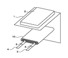
図1は、この発明の実施の第1の形態による非水電解質二次電池の一例の構成を示す。この非水電解質二次電池は、電池素子10を防湿性ラミネートフィルムからなる外装材1に収容し、電池素子10の周囲を溶着することにより封止してなる。電池素子10には、正極リード3および負極リード4が備えられ、これらのリードは、外装材1に挟まれて外部へと引き出される。正極リード3および負極リード4のそれぞれの両面には、外装材1との接着性を向上させるために樹脂片5および樹脂片6が被覆されている。
FIG. 1 shows a configuration of an example of a nonaqueous electrolyte secondary battery according to a first embodiment of the present invention. This non-aqueous electrolyte secondary battery is formed by housing the
[外装材]
外装材1は、例えば、接着層、金属層、表面保護層を順次積層した積層構造を有する。接着層は高分子フィルムからなり、この高分子フィルムを構成する材料としては、例えばポリプロピレン(PP)、ポリエチレン(PE)、無延伸ポリプロピレン(CPP)、直鎖状低密度ポリエチレン(LLDPE)、低密度ポリエチレン(LDPE)が挙げられる。金属層は金属箔からなり、この金属箔を構成する材料としては、例えばアルミニウム(Al)が挙げられる。また、金属箔を構成する材料としては、アルミニウム以外の金属を用いることも可能である。表面保護層を構成する材料としては、例えばナイロン(Ny)、ポリエチレンテレフタレート(PET)が挙げられる。なお、接着層側の面が、電池素子10を収納する側の収納面となる。
[Exterior material]
The
[電池素子]
以下、電池素子10の構成について説明する。図2は、図1に示した電池素子10の一部を拡大して表すものである。この電池素子10は、例えば、図2に示すように、両面にゲル電解質層15が設けられた帯状の負極13と、セパレータ14と、両面にゲル電解質層15が設けられた帯状の正極12と、セパレータ14とを積層し、長手方向に巻回されてなる巻回型の電池素子10である。なお、上記の実施の第1の形態の他、例えば電池素子10は、ゲル電解質を利用せず、非水電解液のみで構成することもできる。さらに、同様な電池素子をラミネートフィルムの代わりに金属ケースに収納した角型電池のような実施形態も可能である。
[Battery element]
Hereinafter, the configuration of the
[正極]
正極12は、帯状の正極集電体12Aと、この正極集電体12Aの両面に形成された正極活物質層12Bとからなる。正極集電体12Aは、例えばアルミニウム(Al)などからなる金属箔である。
[Positive electrode]
The
正極活物質層12Bは、例えば正極活物質と、導電剤と、結着剤とを含有して構成されている。正極活物質としては、リチウムイオンをドープ・脱ドープ可能な公知の正極活物質材料を用いることができ、特に限定されないが、種々の酸化物、例えば二酸化マンガン、リチウムマンガン複合酸化物、リチウム含有ニッケル酸化物、リチウム含有コバルト酸化物、リチウム含有ニッケルコバルト酸化物、リチウム含有鉄酸化物、リチウムを含むバナジウム酸化物や、二硫化チタン、二硫化モリブデンなどのカルコゲン化合物などを挙げることができる。中でも、リチウム含有コバルト酸化物(例えば、LiCoO2)、リチウム含有ニッケルコバルト酸化物(例えば、LiNi0.8Co0.2O2)、リチウムマンガン複合酸化物(例えば、LiMn2O4、LiMnO2)を用いると、高電圧が得られるために好ましい。なお、正極活物質としては、1種類の酸化物を単独で使用しても、あるいは2種類以上の酸化物を混合して使用しても良い。
The positive electrode
なお、正極活物質材料としては、上述の正極活物質を複数種混合して用いることもできる。 Note that, as the positive electrode active material, a plurality of the above-described positive electrode active materials can be mixed and used.
導電剤としては、正極活物質に適量混合して導電性を付与できるものであれば特に制限はないが、例えばカーボンブラックあるいはグラファイトなどの炭素材料等が用いられる。また、結着剤としては、通常この種の電池の正極合剤に用いられている公知の結着剤を用いることができるが、好ましくはポリフッ化ビニル、ポリフッ化ビニリデン、ポリテトラフルオロエチレン等のフッ素系樹脂が用いられる。 The conductive agent is not particularly limited as long as an appropriate amount can be mixed with the positive electrode active material to impart conductivity, and for example, a carbon material such as carbon black or graphite is used. As the binder, a known binder that is usually used in a positive electrode mixture of this type of battery can be used, and preferably polyvinyl fluoride, polyvinylidene fluoride, polytetrafluoroethylene, etc. A fluorine resin is used.
正極12の長手方向の一端部には、例えばスポット溶接または超音波溶接で接続された正極リード3が設けられている。この正極リード3は金属箔、網目状のものが望ましいが、電気化学的および化学的に安定であり、導通がとれるものであれば金属でなくとも問題はない。正極リード3の材料としては、例えばアルミニウム等の金属を用いることができる。
One end of the
[負極]
負極13は、帯状の負極集電体13Aと、この負極集電体13Aの両面に形成された負極活物質層13Bとからなる。負極集電体13Aは、負極集電体13Aとしては、例えば、銅(Cu)箔、ニッケル箔あるいはステンレス箔などの金属箔により構成されている。
[Negative electrode]
The
負極活物質層13Bは、例えば負極活物質と、必要であれば導電剤と、結着剤とを含有して構成されている。負極活物質としては、リチウムをドープ・脱ドープ可能な炭素材料、結晶質、非結晶質金属酸化物が用いられる。具体的に、リチウムをドープ・脱ドープ可能な炭素材料としては、グラファイト、難黒鉛化性炭素材料、易黒鉛化性炭素材料、結晶構造が発達した高結晶性炭素材料等が挙げられる。より具体的には、熱分解炭素類、コークス類(ピッチコークス、ニードルコークス、石油コークス)、黒鉛類、ガラス状炭素類、有機高分子化合物焼成体(フェノール樹脂、フラン樹脂等を適当な温度で焼成し炭素化したもの)、炭素繊維や活性炭、カーボンブラック等の炭素材料あるいはポリアセチレン等のポリマー等を使用することができる。 The negative electrode active material layer 13B includes, for example, a negative electrode active material, a conductive agent if necessary, and a binder. As the negative electrode active material, a carbon material, crystalline, or amorphous metal oxide that can be doped / undoped with lithium is used. Specifically, examples of the carbon material that can be doped / dedoped with lithium include graphite, non-graphitizable carbon material, graphitizable carbon material, and highly crystalline carbon material with a developed crystal structure. More specifically, pyrolytic carbons, cokes (pitch coke, needle coke, petroleum coke), graphites, glassy carbons, organic polymer compound fired bodies (phenolic resin, furan resin, etc.) at an appropriate temperature. Baked and carbonized), carbon fibers, activated carbon, carbon materials such as carbon black, polymers such as polyacetylene, and the like can be used.
また、他の負極活物質材料として、リチウムと合金を形成可能な金属、またはこのような金属の合金化合物が挙げられる。ここで言う合金化合物とは、具体的にはリチウムと合金を形成可能なある金属元素をMとしたとき、MpM’qLir(式中、M’はLi元素およびM元素以外の1つ以上の金属元素である。また、pは0より大きい数値であり、q,rは0以上の数値である。)で表される化合物である。さらに、この発明では半導体元素であるB,Si,As等の元素も金属元素に含めることとする、具体的には、マグネシウム(Mg),ホウ素(B),アルミニウム(Al),ガリウム(Ga),インジウム(In),ケイ素(Si),ゲルマニウム(Ge),スズ(Sn),鉛(Pb),アンチモン(Sb),ビスマス(Bi),カドミウム(Cd)、銀(Ag)、亜鉛(Zn)、ハフニウム(Hf)、ジルコニウム(Zr)、イットリウム(Y)の各金属とそれらの合金化合物、すなわち、例えばLi−Al,Li−Al−M(式中、Mは2A族、3B族、4B族遷移金属元素のうち1つ以上からなる。)、AlSb、CuMgSb等が挙げられる。 As another negative electrode active material, a metal capable of forming an alloy with lithium, or an alloy compound of such a metal can be given. Specifically, the alloy compound referred to here is M p M ′ q Li r (where M ′ is 1 other than Li element and M element), where M is a metal element capable of forming an alloy with lithium. And p is a numerical value greater than 0, and q and r are numerical values greater than or equal to 0). Furthermore, in the present invention, elements such as B, Si, As and the like, which are semiconductor elements, are also included in the metal element, specifically, magnesium (Mg), boron (B), aluminum (Al), gallium (Ga). , Indium (In), silicon (Si), germanium (Ge), tin (Sn), lead (Pb), antimony (Sb), bismuth (Bi), cadmium (Cd), silver (Ag), zinc (Zn) , Hafnium (Hf), zirconium (Zr), yttrium (Y) and their alloy compounds, for example, Li-Al, Li-Al-M (wherein M is a group 2A, 3B, 4B) It consists of one or more transition metal elements.), AlSb, CuMgSb and the like.
上述したような元素の中でも、リチウムと合金形成可能な元素としては3B族典型元素を用いるのが好ましい。中でも、SiやSn等の元素またはその合金を用いるのが好ましく、さらにSiまたはSi合金が特に好適である。Si合金またはSn合金として具体的には、MxSi、MxSn(式中、MはSiまたはSnを除く1つ以上の金属元素である。)で表される化合物で、具体的にはSiB4、SiB6、Mg2Si、Mg2Sn、Ni2Si、TiSi2、MoSi2、CoSi2、NiSi2、CaSi2、CrSi2、Cu5Si、FeSi2、MnSi2、NbSi2、TaSi2、VSi2、WSi2、ZnSi2等が挙げられる。 Among the elements described above, it is preferable to use a group 3B typical element as an element capable of forming an alloy with lithium. Among them, it is preferable to use an element such as Si or Sn or an alloy thereof, and Si or Si alloy is particularly preferable. Specifically, the Si alloy or the Sn alloy is a compound represented by M x Si, M x Sn (wherein M is one or more metal elements excluding Si or Sn), specifically, SiB 4 , SiB 6 , Mg 2 Si, Mg 2 Sn, Ni 2 Si, TiSi 2 , MoSi 2 , CoSi 2 , NiSi 2 , CaSi 2 , CrSi 2 , Cu 5 Si, FeSi 2 , MnSi 2 , NbSi 2 , TaSi 2 , VSi 2 , WSi 2 , ZnSi 2 and the like.
さらに、1つ以上の非金属元素を含む、炭素を除く4B族化合物もこの発明の負極材料として利用することができる。負極材料中には、2種類以上の4B族元素が含まれていても良い。また、リチウムを含む4B族以外の金属元素が含まれていても良い。例示するならばSiC、Si3N4、Si2N2O、Ge2N2O、SiOx(0<x≦2)、SNOx(0<x≦2)、LiSiO、LiSNO等である。 Furthermore, a 4B group compound excluding carbon containing one or more nonmetallic elements can also be used as the negative electrode material of the present invention. Two or more types of 4B group elements may be contained in the negative electrode material. Moreover, metal elements other than the 4B group containing lithium may be contained. For example, SiC, Si 3 N 4 , Si 2 N 2 O, Ge 2 N 2 O, SiO x (0 <x ≦ 2), SNO x (0 <x ≦ 2), LiSiO, LiSNO, and the like.
導電剤としては、正極活物質に適量混合して導電性を付与できるものであれば特に制限はないが、例えばカーボンブラックあるいはグラファイトなどの炭素材料等が用いられる。また、結着剤としては、例えばポリフッ化ビニリデン、スチレンブタジエンゴム等が用いられる。 The conductive agent is not particularly limited as long as an appropriate amount can be mixed with the positive electrode active material to impart conductivity, and for example, a carbon material such as carbon black or graphite is used. As the binder, for example, polyvinylidene fluoride, styrene butadiene rubber or the like is used.
また、負極13の長手方向の一端部にも正極12と同様に、例えばスポット溶接または超音波溶接で接続された負極リード4が設けられている。この負極リード4は電気化学的および化学的に安定であり、導通がとれるものであれば金属でなくとも問題はない。負極リード4の材料としては、例えば銅(Cu)、ニッケル(Ni)等を用いることができる。
Further, similarly to the
[電解質]
ゲル電解質層15は、電解液と、この電解液を保持する保持体となる高分子化合物とを含み、いわゆるゲル状となっている。ゲル電解質層15は高いイオン伝導率を得ることができるとともに、電池の漏液を防止できるので好ましい。
[Electrolytes]
The
電解液としては、非水溶媒に電解質塩を溶解させた非水電解液を用いることができる。非水溶媒としては、例えば、エチレンカーボネートおよびプロピレンカーボネートのうちの少なくとも一方を含んでいることが好ましい。サイクル特性を向上させることができるからである。特に、エチレンカーボネートとプロピレンカーボネートとを混合して含むようにすれば、よりサイクル特性を向上させることができるので好ましい。非水溶媒としては、また、ジエチルカーボネート、ジメチルカーボネート、エチルメチルカーボネートまたはメチルプロピルカーボネート等の鎖状炭酸エステルの中から、少なくとも1種を含んでいることが好ましい。サイクル特性をより向上させることができるからである。 As the electrolytic solution, a nonaqueous electrolytic solution in which an electrolyte salt is dissolved in a nonaqueous solvent can be used. As the non-aqueous solvent, for example, it is preferable to contain at least one of ethylene carbonate and propylene carbonate. This is because the cycle characteristics can be improved. In particular, it is preferable to mix and contain ethylene carbonate and propylene carbonate because cycle characteristics can be further improved. The nonaqueous solvent preferably contains at least one of chain carbonates such as diethyl carbonate, dimethyl carbonate, ethyl methyl carbonate, or methyl propyl carbonate. This is because the cycle characteristics can be further improved.
非水溶媒としては、さらに、2,4−ジフルオロアニソールおよびビニレンカーボネートのうちの少なくとも一方を含んでいることが好ましい。2,4−ジフルオロアニソールは放電容量を改善することができ、ビニレンカーボネートはサイクル特性をより向上させることができるからである。特に、これらを混合して含んでいれば、放電容量およびサイクル特性を共に向上させることができるのでより好ましい。 The non-aqueous solvent preferably further contains at least one of 2,4-difluoroanisole and vinylene carbonate. This is because 2,4-difluoroanisole can improve discharge capacity, and vinylene carbonate can further improve cycle characteristics. In particular, it is more preferable that they are mixed and contained because both the discharge capacity and the cycle characteristics can be improved.
非水溶媒としては、さらに、ブチレンカーボネート、γ−ブチロラクトン、γ−バレロラクトン、これら化合物の水素基の一部または全部をフッ素基で置換したもの、1,2−ジメトキシエタン、テトラヒドロフラン、2−メチルテトラヒドロフラン、1,3−ジオキソラン、4−メチル−1,3−ジオキソラン、酢酸メチル、プロピオン酸メチル、アセトニトリル、グルタロニトリル、アジポニトリル、メトキシアセトニトリル、3−メトキシプロピロニトリル、N,N−ジメチルフォルムアミド、N−メチルピロリジノン、N−メチルオキサゾリジノン、N,N−ジメチルイミダゾリジノン、ニトロメタン、ニトロエタン、スルホラン、ジメチルスルフォキシドあるいはリン酸トリメチル等のいずれか1種または2種以上を含んでいてもよい。 Non-aqueous solvents further include butylene carbonate, γ-butyrolactone, γ-valerolactone, those in which part or all of the hydrogen groups of these compounds are substituted with fluorine groups, 1,2-dimethoxyethane, tetrahydrofuran, 2-methyl Tetrahydrofuran, 1,3-dioxolane, 4-methyl-1,3-dioxolane, methyl acetate, methyl propionate, acetonitrile, glutaronitrile, adiponitrile, methoxyacetonitrile, 3-methoxypropironitrile, N, N-dimethylformamide N-methylpyrrolidinone, N-methyloxazolidinone, N, N-dimethylimidazolidinone, nitromethane, nitroethane, sulfolane, dimethyl sulfoxide or trimethyl phosphate may be included. Yes.
組み合わせる電極によっては、上記非水溶媒群に含まれる物質の水素原子の一部または全部をフッ素原子で置換したものを用いることにより、電極反応の可逆性が向上する場合がある。したがって、これらの物質を適宜用いることも可能である。 Depending on the electrode to be combined, the reversibility of the electrode reaction may be improved by using a material in which part or all of the hydrogen atoms of the substance contained in the non-aqueous solvent group are substituted with fluorine atoms. Therefore, these substances can be used as appropriate.
電解質塩であるリチウム塩としては、例えば、LiPF6、LiBF4、LiAsF6、LiClO4、LiB(C6H5)4、LiCH3SO3、LiCF3SO3、LiN(SO2CF3)2、LiC(SO2CF3)3、LiAlCl4、LiSiF6、LiCl、LiBF2(ox)、LiBOB、あるいはLiBrが適当であり、これらのうちのいずれか1種または2種以上が混合して用いることができる。なかでも、LiPF6は、高いイオン伝導性を得ることができるとともに、サイクル特性を向上させることができるので好ましい。 Examples of the lithium salt that is an electrolyte salt include LiPF 6 , LiBF 4 , LiAsF 6 , LiClO 4 , LiB (C 6 H 5 ) 4 , LiCH 3 SO 3 , LiCF 3 SO 3 , LiN (SO 2 CF 3 ) 2. , LiC (SO 2 CF 3 ) 3 , LiAlCl 4 , LiSiF 6 , LiCl, LiBF 2 (ox), LiBOB, or LiBr are suitable, and one or more of these are used in combination. be able to. Among them, LiPF 6 is preferable because it can obtain high ion conductivity and can improve cycle characteristics.
高分子化合物としては、例えば、ポリアクリロニトリル、ポリフッ化ビニリデン、フッ化ビニリデンとヘキサフルオロプロピレンとの共重合体、ポリテトラフルオロエチレン、ポリヘキサフルオロプロピレン、ポリエチレンオキサイド、ポリプロピレンオキサイド、ポリフォスファゼン、ポリシロキサン、ポリ酢酸ビニル、ポリビニルアルコール、ポリメタクリル酸メチル、ポリアクリル酸、ポリメタクリル酸、スチレン−ブタジエンゴム、ニトリル−ブタジエンゴム、ポリスチレンあるいはポリカーボネートを挙げることができる。特に電気化学的な安定性の点からは、ポリアクリロニトリル、ポリフッ化ビニリデン、ポリヘキサフルオロプロピレンあるいはポリエチレンオキサイドが好ましい。 Examples of the polymer compound include polyacrylonitrile, polyvinylidene fluoride, a copolymer of vinylidene fluoride and hexafluoropropylene, polytetrafluoroethylene, polyhexafluoropropylene, polyethylene oxide, polypropylene oxide, polyphosphazene, and polysiloxane. , Polyvinyl acetate, polyvinyl alcohol, polymethyl methacrylate, polyacrylic acid, polymethacrylic acid, styrene-butadiene rubber, nitrile-butadiene rubber, polystyrene or polycarbonate. In particular, from the viewpoint of electrochemical stability, polyacrylonitrile, polyvinylidene fluoride, polyhexafluoropropylene, or polyethylene oxide is preferable.
[セパレータ]
セパレータ14は、例えばポリプロピレン(PP)あるいはポリエチレン(PE)などのポリオレフィン系の材料よりなる多孔質膜、またはセラミック製の不織布などの無機材料よりなる多孔質膜により構成されており、これら2種以上の多孔質膜を積層した構造とされていてもよい。中でも、ポリエチレン、ポリプロピレンの多孔質フィルムが最も有効である。
[Separator]
The
一般的にセパレータ14の厚みは5〜50μmが好適に使用可能であるが、7〜30μmがより好ましい。セパレータ14は、厚すぎると活物質の充填量が低下して電池容量が低下するとともに、イオン伝導性が低下して電流特性が低下する。逆に薄すぎると、膜の機械的強度が低下する。
In general, the thickness of the
[非水電解質二次電池の作製]
次に、この発明の実施の第1の形態による非水電解質二次電池の作製方法について説明する。まず、正極12を作製する。上述の正極活物質、結着剤、導電剤を均一に混合して正極合剤とし、この正極合剤を溶剤中に分散させ、必要に応じてボールミル、サンドミル、二軸混練機等によりスラリー状にする。溶剤としては、電極材料に対して不活性であり、かつ結着剤を溶解し得るものであれば特に限定はなく、無機溶剤、有機溶剤のいずれも用いることができるが、例えばN−メチル−2−ピロリドン(NMP)等が用いられる。なお、正極活物質、導電剤、結着剤および溶剤は、均一に分散していればよく、その混合比は問わない。次いで、このスラリーをドクターブレード法等により正極集電体12Aの両面に均一に塗布する。その際に、正極活物質の比表面積が、例えば、0.1m2/g〜0.8m2/g程度の範囲内となるように調整すると好ましい。さらに、高温で乾燥させて溶剤を飛ばした後、例えばロールプレス機で圧縮成型することにより正極活物質層12Bが形成される。これにより、正極12が作製される。
[Preparation of non-aqueous electrolyte secondary battery]
Next, a method for manufacturing a nonaqueous electrolyte secondary battery according to the first embodiment of the present invention will be described. First, the
次に、負極13を作製する。上述の負極活物質、結着剤、導電剤を均一に混合して負極合剤とし、溶剤中に分散させてスラリー状にする。このとき、正極合剤の場合と同様にボールミル、サンドミル、二軸混練機等を用いてもよい。溶剤としては、例えばN−メチル−2−ピロリドン、メチルエチルケトン等が用いられる。なお、負極活物質、導電剤、結着剤および溶剤は、正極活物質と同様に、その混合比は問わない。次いで、このスラリーをドクターブレード法等により負極集電体13Aの両面に均一に塗布する。その際に、負極活物質の比表面積が、例えば、0.2m2/g〜0.7m2/g程度の範囲内となるように調整すると好ましい。さらに、高温で乾燥させて溶剤を飛ばした後、例えばロールプレス機で圧縮成型することにより負極活物質層13Bが形成される。これにより、負極13が作製される。
Next, the
なお、塗布装置については特に限定されず、スライドコーティングやエクストルージョン型のダイコーティング、リバースロール、グラビア、ナイフコーター、キスコーター、マイクログラビア、ロッドコーター、ブレードコーターなどが使用できる。また、乾燥方法についても特に制限はないが、放置乾燥、送風乾燥機、温風乾燥機、赤外線加熱機、遠赤外線加熱機などが使用できる。 The coating apparatus is not particularly limited, and slide coating, extrusion type die coating, reverse roll, gravure, knife coater, kiss coater, micro gravure, rod coater, blade coater and the like can be used. Also, the drying method is not particularly limited, but standing drying, blower dryer, hot air dryer, infrared heater, far infrared heater, and the like can be used.
上述のようにして作製された正極12および負極13のそれぞれに、溶媒と、電解質塩と、高分子化合物と、混合溶媒とを含む前駆溶液を塗布し、混合溶媒を揮発させてゲル電解質層15を形成する。なお、予め正極集電体12Aの端部に正極リード3を溶接により取り付けるとともに、負極集電体13Aの端部に負極リード4を溶接により取り付けるようにする。
A
次に、ゲル電解質層15が形成された正極12と負極13とをセパレータ14を介して積層し積層体とした後、この積層体をその長手方向に巻回して、巻回型の電池素子10を形成する。
Next, the
次に、ラミネートフィルムからなる外装材1を深絞り加工することで凹部2を形成し、電池素子10をこの凹部2に挿入し、外装材1の未加工部分を凹部2上部に折り返し、凹部2の外周部分を熱溶着し密封する。以上により、この発明の一実施形態による非水電解質二次電池が作製される。
Next, the
[インピーダンスの測定]
次に、上述のようにして作製された非水電解質二次電池の正極および負極の交流インピーダンスを測定する。先ず、所定の周波数範囲における電池の交流インピーダンスを測定する。電池の交流インピーダンスの測定には、ポテンショ/ガルバノスタットや周波数応答アナライザ等の測定機器が用いられる。
[Measurement of impedance]
Next, the AC impedance of the positive electrode and the negative electrode of the nonaqueous electrolyte secondary battery manufactured as described above is measured. First, the AC impedance of the battery in a predetermined frequency range is measured. Measurement equipment such as a potentio / galvanostat or a frequency response analyzer is used to measure the AC impedance of the battery.
このように非水電解質二次電池の交流インピーダンスを測定した場合、各周波数における交流インピーダンスの値は、基準となる参照電極が存在しないため、正極12および負極13のインピーダンスが合成された値である。
When the AC impedance of the nonaqueous electrolyte secondary battery is measured in this way, the value of the AC impedance at each frequency is a value obtained by combining the impedances of the
しかしながら、通常、正極12と負極13とでは電極特性が異なるため、正極12または負極13のみの周波数に対するインピーダンス応答は異なり、例えば、所定の周波数においては、正極12または負極13によるインピーダンスが主に現れる。
However, since the
したがって、所定の周波数において、インピーダンスの実数成分および虚数成分のうち、周波数に依存する虚数成分を比較することにより、正極12および負極13のインピーダンスの大小関係を知ることができる。インピーダンスは充電状態により変化するため、測定は、定格容量に対して充電率100%の状態で行う。
Therefore, the magnitude relationship between the impedances of the
図3は、この発明の実施の第1の形態による非水電解質二次電池の周波数とインピーダンスの虚数成分の絶対値との関係の一例を示すグラフである。図3に示すように、例えば、周波数が100Hzの付近に平坦部があり、周波数が5Hzの付近にインピーダンスのピークが見られることから、この2つの周波数におけるインピーダンスの虚数成分の絶対値を基準とすることができる。 FIG. 3 is a graph showing an example of the relationship between the frequency of the nonaqueous electrolyte secondary battery according to the first embodiment of the present invention and the absolute value of the imaginary component of the impedance. As shown in FIG. 3, for example, there is a flat portion in the vicinity of the frequency of 100 Hz, and an impedance peak is seen in the vicinity of the frequency of 5 Hz. Therefore, the absolute value of the imaginary component of the impedance at these two frequencies is used as a reference. can do.
この非水電解質二次電池の場合には、周波数100Hzにおけるインピーダンスの虚数成分の絶対値Z1が主に負極13のインピーダンスを示し、周波数5Hzにおけるインピーダンスの虚数成分の絶対値Z2が主に正極12のインピーダンスを示しており、このZ1とZ2とを比較することにより、電池の正極12および負極13のインピーダンスの大小関係を知ることができる。
In the case of this nonaqueous electrolyte secondary battery, the absolute value Z1 of the imaginary component of the impedance at a frequency of 100 Hz mainly indicates the impedance of the
次に、上述のように測定された負極のインピーダンスZ1および正極のインピーダンスZ2に基づき、インピーダンス比Z2/Z1を算出する。そして、インピーダンス比Z2/Z1が所定の範囲内にあるか否かに応じて、この非水電解質二次電池の良否を判別する。例えば、インピーダンス比Z2/Z1が所定の範囲内にある場合には良品とし、インピーダンス比Z2/Z1が所定の範囲外である場合には不良品として排除する。 Next, based on the negative electrode impedance Z1 and the positive electrode impedance Z2 measured as described above, an impedance ratio Z2 / Z1 is calculated. And the quality of this nonaqueous electrolyte secondary battery is discriminate | determined according to whether impedance ratio Z2 / Z1 exists in the predetermined range. For example, when the impedance ratio Z2 / Z1 is within a predetermined range, the product is rejected, and when the impedance ratio Z2 / Z1 is outside the predetermined range, the product is rejected as a defective product.
このインピーダンス比Z2/Z1の値は、例えば、0.2≦Z2/Z1≦1の範囲内にあると好ましい。 The value of the impedance ratio Z2 / Z1 is preferably in the range of 0.2 ≦ Z2 / Z1 ≦ 1, for example.
なお、例えば、以下に示すようにして、非水電解質二次電池の良否を判別するようにしてもよい。即ち、交流インピーダンスを測定する測定機器をPC(Personal Computer)などのコンピュータに接続し、測定機器により測定された交流インピーダンスの虚数成分の絶対値をコンピュータに出力する。そして、コンピュータにて測定装置から供給された交流インピーダンスの虚数成分の絶対値が所定の範囲にあるか否かを判別し、交流インピーダンスの虚数成分の絶対値が所定の範囲内にある場合には、例えば、コンピュータに接続されたモニタ等の表示部に良品であることを表示する。一方、交流インピーダンスの虚数成分の絶対値が所定の範囲外にある場合には、例えば、表示部に不良品であることを表示する。 For example, the quality of the nonaqueous electrolyte secondary battery may be determined as follows. That is, a measuring device that measures AC impedance is connected to a computer such as a PC (Personal Computer), and the absolute value of the imaginary component of the AC impedance measured by the measuring device is output to the computer. Then, the computer determines whether the absolute value of the imaginary component of the AC impedance supplied from the measuring device is within a predetermined range, and if the absolute value of the imaginary component of the AC impedance is within the predetermined range, For example, a non-defective product is displayed on a display unit such as a monitor connected to the computer. On the other hand, when the absolute value of the imaginary component of the AC impedance is outside the predetermined range, for example, the display unit displays that the product is defective.
次に、この発明の実施の第1の形態による非水電解質二次電池における、充放電サイクル特性について説明する。この発明の実施の第1の形態による非水電解質二次電池は、負極活物質と正極活物質との比表面積比、および負極13と正極12とのインピーダンス比を調整することにより、充放電サイクル特性を向上させることができる。
Next, the charge / discharge cycle characteristics in the nonaqueous electrolyte secondary battery according to the first embodiment of the present invention will be described. The nonaqueous electrolyte secondary battery according to the first embodiment of the present invention has a charge / discharge cycle by adjusting the specific surface area ratio between the negative electrode active material and the positive electrode active material and the impedance ratio between the
正極12および負極13の比表面積は、ある程度のバランスがとれている必要がある。例えば、正極12および負極13のうち、どちらか一方の活物質の比表面積が他方に比べて非常に大きい場合、正負極間でのリチウムの授受の効率が悪化してしまう。
The specific surface areas of the
また、正極12および負極13のインピーダンスは、正極12および負極13の活物質の比表面積に依存している。通常、活物質の比表面積が大きい場合には、インピーダンスは小さくなり、比表面積が小さい場合には、インピーダンスは大きくなる。そのため、充放電サイクル特性を向上させるためには、インピーダンス比が所定の範囲内に収まるようにする必要がある。
The impedance of the
したがって、充放電サイクル特性を向上させるためには、正極12および負極13における活物質の比表面積比が所定の範囲内に収まるようにするとともに、インピーダンス比が所定の範囲内に収まるようにする必要がある。
Therefore, in order to improve the charge / discharge cycle characteristics, the specific surface area ratio of the active material in the
この非水電解質二次電池の場合、具体的には、例えば、比表面積比S2/S1が0.5よりも小さく、インピーダンス比Z2/Z1が1よりも大きい場合は、正極12のインピーダンスが負極13のインピーダンスよりも大きいために正極12の劣化が生じ、充放電サイクル特性が低下する。
In the case of this non-aqueous electrolyte secondary battery, specifically, for example, when the specific surface area ratio S2 / S1 is smaller than 0.5 and the impedance ratio Z2 / Z1 is larger than 1, the impedance of the
一方、例えば、比表面積比S2/S1が4よりも大きく、インピーダンス比Z2/Z1が0.2よりも小さい場合は、負極13のインピーダンスが正極12のインピーダンスよりも極端に大きいために、負極13の劣化が生じ、充放電サイクル特性が低下する。
On the other hand, for example, when the specific surface area ratio S2 / S1 is larger than 4 and the impedance ratio Z2 / Z1 is smaller than 0.2, since the impedance of the
したがって、この場合、比表面積比S2/S1が0.5≦S2/S1≦4となるように正極および負極の活物質の比表面積を制御するとともに、インピーダンス比Z2/Z1が0.2≦Z2/Z1≦1となるようにインピーダンスを制御することにより、良好な充放電サイクル特性の非水電解質二次電池を得ることができる。また、正極12および負極13のインピーダンス比が上述の範囲内に収まっているかどうかを判断することにより、その非水電解質二次電池の充放電サイクル特性が良好であるかどうかを簡易的に判断することができる。
Accordingly, in this case, the specific surface area of the active material of the positive electrode and the negative electrode is controlled so that the specific surface area ratio S2 / S1 is 0.5 ≦ S2 / S1 ≦ 4, and the impedance ratio Z2 / Z1 is 0.2 ≦ Z2. By controlling the impedance so that / Z1 ≦ 1, a non-aqueous electrolyte secondary battery having good charge / discharge cycle characteristics can be obtained. In addition, by determining whether the impedance ratio of the
次に、この発明の実施の第2の形態について、図面を参照して説明する。図4は、この発明の実施の第2の形態による非水電解質二次電池の一例の構成を示す断面図である。この非水電解質二次電池は、いわゆる円筒形と呼ばれるものであり、ほぼ中空円柱状の電池缶31の内部に、帯状の正極32と帯状の負極33とがセパレータ34を介して対向配置され、巻回された電池素子50を有している。電池缶31は、例えばニッケル(Ni)のめっきがされた鉄(Fe)により構成されており、一端部が閉鎖され他端部が開放されている。電池缶31の内部には、液状の電解質である電解液が注入されセパレータ34に含浸されている。また、電池素子50を挟むように巻回周面に対して垂直に一対の絶縁板35、36がそれぞれ配置されている。
Next, a second embodiment of the present invention will be described with reference to the drawings. FIG. 4 is a cross-sectional view showing a configuration of an example of a nonaqueous electrolyte secondary battery according to the second embodiment of the present invention. This non-aqueous electrolyte secondary battery is a so-called cylindrical shape, and a strip-shaped
電池缶31の開放端部には、電池蓋37と、この電池蓋37の内側に設けられた安全弁機構38および熱感抵抗素子(Positive Temperature Coefficient;PTC素子)39とが、ガスケット40を介してかしめられることにより取り付けられており、電池缶31の内部は密閉されている。電池蓋37は、例えば、電池缶31と同様の材料により構成されている。安全弁機構38は、熱感抵抗素子39を介して電池蓋37と電気的に接続されており、内部短絡あるいは外部からの加熱などにより電池の内圧が一定以上となった場合にディスク板41が反転して電池蓋37と電池素子50との電気的接続を切断するようになっている。熱感抵抗素子39は、温度が上昇すると抵抗値の増大により電流を制限し、大電流による異常な発熱を防止するものである。ガスケット40は、例えば、絶縁材料により構成されており、表面にはアスファルトが塗布されている。
At the open end of the battery can 31, a
電池素子50は、例えば、センターピン42を中心に巻回されている。電池素子50の正極32にはアルミニウム(Al)などよりなる正極リード43が接続されており、負極33にはニッケルなどよりなる負極リード44が接続されている。正極リード43は安全弁機構38に溶接されることにより電池蓋37と電気的に接続されており、負極リード44は電池缶31に溶接され電気的に接続されている。
The
以下、電池缶31に収容された電池素子50の構成について説明する。図5は、図4に示した電池素子50の一部を拡大して表すものである。なお、正極32および正極33に用いられる材料やセパレータ34については、上述の実施の第1の形態と同様であるため、説明を省略する。
Hereinafter, the configuration of the
[正極]
正極32は、図5に示すように、例えば、対向する一対の面を有する正極集電体32Aと、正極集電体32Aの両面に設けられた正極活物質層32Bとを有している。なお、正極集電体32Aの片面のみに正極活物質層32Bが設けられた領域を有するようにしてもよい。正極集電体32Aは、例えばアルミニウム(Al)箔,ニッケル箔あるいはステンレス箔などの金属箔により構成されている。なお、正極活物質層32Bに用いられる材料については、上述の実施の第1の形態で説明したのと同様であるため、省略する。
[Positive electrode]
As shown in FIG. 5, the
正極32の一端部には、スポット溶接または超音波溶接で接続された1本の正極リード43が溶着される。この正極リード43は金属箔、網目状のものが望ましいが、電気化学的および化学的に安定であり、導通がとれるものであれば金属でなくとも問題はない。正極リード43の材料としては、例えばAl等が挙げられる。正極リード43は、正極32の端部に設けられた正極集電体露出部に溶着されるようにする。
One
[負極]
負極33は、図5に示すように、例えば、対向する一対の面を有する負極集電体33Aと、負極集電体33Aの両面に設けられた負極活物質層33Bとを有している。なお、負極集電体33Aの片面のみに負極活物質層33Bが設けられた領域を有するようにしてもよい。負極集電体33Aは、例えば銅箔,ニッケル箔あるいはステンレス箔などの金属箔により構成されている。なお、負極活物質層33Bに用いられる材料については、上述の実施の第1の形態で説明したのと同様であるため、省略する。
[Negative electrode]
As shown in FIG. 5, the
負極33の一端部には、スポット溶接または超音波溶接で接続された1本の負極リード44を有している。この負極リード44は電気化学的および化学的に安定であり、導通がとれるものであれば金属でなくとも問題はない。負極リード44の材料としては、例えば銅、ニッケル等が挙げられる。正極リード溶接部分と同様に、負極リード44は、負極33の端部に設けられた負極集電体露出部に溶着されるようにする。
One end of the
[電解質]
電解液の構成(すなわち液状の溶媒、電解質塩および添加剤)は、上述の実施の第1の形態と同様であるため、詳細については省略する。電解質としては、非水溶媒に電解質塩が溶解された非水電解液を用いることができる。非水電解液は、非水溶媒と電解質塩とを適宜組み合わせて調整されるが、これら有機溶媒は、この種の電池に一般的に使用される材料であればいずれも使用可能である。
[Electrolytes]
The configuration of the electrolytic solution (that is, the liquid solvent, the electrolyte salt, and the additive) is the same as that in the first embodiment described above, and thus the details are omitted. As the electrolyte, a nonaqueous electrolytic solution in which an electrolyte salt is dissolved in a nonaqueous solvent can be used. The nonaqueous electrolytic solution is prepared by appropriately combining a nonaqueous solvent and an electrolyte salt, and any organic solvent can be used as long as it is a material generally used for this type of battery.
[非水電解質二次電池の作製]
次に、円筒型の非水電解質二次電池の作製方法について説明する。まず、上述の実施の第1の形態と同様にして正極32および負極33を作製する。作製された正極32および負極33を、正極32、セパレータ34、負極33、セパレータ34の順に積層し、巻回して電池素子50とする。このとき、正極32および負極33にそれぞれ設けた集電体露出部が対向した集電体対向面を設けるようにして積層し、電池素子50の最外周部、最内周部および中間層部において集電体対向面が1周以上となるように構成する。固体状あるいはゲル状の電解質を用いる場合は、電解質溶液を正極32および負極33の表面に均一に塗布し、常温もしくは高温雰囲気下で乾燥させ、溶媒を気化・除去して電解質層を形成する。その後セパレータ34とともに積層して巻回し、電池素子50とする。
[Production of non-aqueous electrolyte secondary battery]
Next, a method for manufacturing a cylindrical nonaqueous electrolyte secondary battery will be described. First, the
次いで、上述の電池素子50を電池缶31に収容する。このとき、電池素子50の巻回面の負極リード導出側が、絶縁性樹脂により作製された絶縁板36で覆われるようにして収容する。この後、一方の電極棒を電池素子巻回中心部から挿入し、もう一方の電極棒を電池缶底面外側に配置して抵抗溶接を行い、負極リード44を電池缶に溶接する。
Next, the
負極リード44と電池缶31とを溶接後、センターピン42を挿入し、電池缶開放端部に位置する巻回面部分にも絶縁板35を配置して電解液を注液する。さらに、内側に安全弁機構38およびPTC素子39を設けた電池蓋37に正極リード43を接続するとともに、この電池蓋7が絶縁封口ガスケット40を介してかしめられることにより取り付けられ、電池缶31の内部が密閉される。
After welding the
なお、正極リード43は製造工程上、ある程度の長さを持ったものを用いる必要がある。これは、あらかじめ正極リード43を電池蓋37に設けられた安全弁機構38に接続してから電池缶31の開放端部を密閉するためであり、正極リード43が短いほど正極リード43と電池蓋37の接続が困難になる。このため、正極リード43が電池内部で略U字状に屈曲して収容される。
The
[インピーダンスの測定]
次に、上述のようにして作製された非水電解質二次電池の負極のインピーダンスZ1および正極のインピーダンスZ2を測定する。そして、測定されたインピーダンスZ1およびZ2に基づき、正極および負極のインピーダンス比Z2/Z1を算出し、このインピーダンス比Z2/Z1の値が所定の範囲内にあるか否かに応じて、この非水電解質二次電池の良否を判別する。なお、インピーダンスおよびインピーダンス比の測定方法については、上述の実施の第1の形態で説明したのと同様であるため、省略する。
[Measurement of impedance]
Next, the impedance Z1 of the negative electrode and the impedance Z2 of the positive electrode of the nonaqueous electrolyte secondary battery manufactured as described above are measured. Then, based on the measured impedances Z1 and Z2, an impedance ratio Z2 / Z1 between the positive electrode and the negative electrode is calculated, and this non-water is determined depending on whether or not the value of the impedance ratio Z2 / Z1 is within a predetermined range. The quality of the electrolyte secondary battery is determined. The method for measuring the impedance and the impedance ratio is the same as that described in the first embodiment, and will not be described.
以下、実施例により、この発明の実施の第1の形態による非水電解質二次電池について、具体的に説明するが、この実施の第1の形態は、これらの実施例のみに限定されるものではない。 Hereinafter, the nonaqueous electrolyte secondary battery according to the first embodiment of the present invention will be specifically described by way of examples. However, the first embodiment is limited to only these examples. is not.
実施例1
先ず、以下のように正極12を作製した。平均粒子径が10μmであり、且つ、比表面積S2が0.4m2/gであるLiCoO2粉末91重量%と、導電剤である黒鉛6重量%と、結着剤であるポリビニリデンフルオライド3重量%とを混合して正極合剤を作製した。この正極合剤をN−メチル−2−ピロリドンに分散させてスラリー状とし、これを正極集電体12Aとなる厚さ20μmの帯状のアルミニウム箔の片面に均一に塗布した後に乾燥させた。そして、ロールプレス機で圧縮成型することによって正極活物質層12Bを作製した。
Example 1
First, the
次に、以下のように負極13を作製した。比表面積S1が0.2m2/gとなるように粉砕して調整した黒鉛粉末90重量%と、結着剤であるポリビニリデンフルオライド10重量%とを混合して負極合剤を作製した。この負極合剤をN−メチル−2−ピロリドンに分散させてスラリー状とし、これを負極集電体13Aとなる厚さ20μmの帯状の銅箔の片面に均一に塗布した後に乾燥させた。そして、ロールプレス機で圧縮成型することによって負極活物質層13Bを作製した。
Next, the
また、以下のようにゲル状電解質を作製した。炭酸エチレン(EC)13.0重量%と、炭酸プロピレン(PC)13.0重量%と、電解質塩であるLiPF64重量%とを混合して可塑剤を調整した。これに対して分子量が600000であるブロック共重合ポリビニリデンフルオライド−co−ヘキサフルオロプロピレン10重量%と、炭酸ジエチル60重量%とを混合して溶解させた。次に、これを負極活物質層13Bの片面に均一に塗布して含浸させた。そして、常温で8時間放置することによって炭酸ジエチルを気化させて除去し、ゲル状電解質を作製した。 Moreover, the gel electrolyte was produced as follows. A plasticizer was prepared by mixing 13.0% by weight of ethylene carbonate (EC), 13.0% by weight of propylene carbonate (PC), and 4% by weight of LiPF 6 as an electrolyte salt. On the other hand, 10% by weight of block copolymer polyvinylidene fluoride-co-hexafluoropropylene having a molecular weight of 600,000 and 60% by weight of diethyl carbonate were mixed and dissolved. Next, this was uniformly applied and impregnated on one surface of the negative electrode active material layer 13B. Then, by standing for 8 hours at room temperature, diethyl carbonate was vaporized and removed, and a gel electrolyte was produced.
最後に、上述したようにゲル状電解質が塗布された正極活物質層12Bと負極活物質層13Bとを、ゲル状電解質が塗布された面同士を対向させて圧着し、電池素子10を作製した。この発電素子を、厚さ180μmの防湿性アルミラミネートフィルム外装中に真空封止して、寸法がおよそ2.5cm×4.0cm×0.46mmである平板型ゲル状電解質電池を作製した。
Finally, as described above, the positive electrode
実施例2
比表面積S1が0.3m2/gとなるように粉砕して調整した黒鉛粉末を負極活物質として用いた以外のことは、実施例1と全て同様にした。
Example 2
The same procedure as in Example 1 was conducted except that graphite powder pulverized and adjusted so that the specific surface area S1 was 0.3 m 2 / g was used as the negative electrode active material.
実施例3
比表面積S1が0.7m2/gとなるように粉砕して調整した黒鉛粉末を負極活物質として用いた以外のことは、実施例1と全て同様にした。
Example 3
The same procedure as in Example 1 was conducted except that graphite powder pulverized and adjusted so that the specific surface area S1 was 0.7 m 2 / g was used as the negative electrode active material.
実施例4
平均粒子径が6μmであり、且つ、比表面積S2が0.8m2/gであるLiCoO2粉末を正極活物質として用いるとともに、比表面積S1が0.3m2/gとなるように粉砕して調整した黒鉛粉末を負極活物質として用いた以外のことは、実施例1と全て同様にした。
Example 4
LiCoO 2 powder having an average particle diameter of 6 μm and a specific surface area S2 of 0.8 m 2 / g is used as a positive electrode active material, and pulverized so that the specific surface area S1 is 0.3 m 2 / g. Except for using the prepared graphite powder as the negative electrode active material, the same procedure as in Example 1 was performed.
実施例5
平均粒子径が20μmであり、且つ、比表面積S2が0.1m2/gであるLiCoO2粉末を正極活物質として用いた以外のことは、実施例1と全て同様にした。
Example 5
Except that LiCoO 2 powder having an average particle diameter of 20 μm and a specific surface area S2 of 0.1 m 2 / g was used as the positive electrode active material, the same procedure as in Example 1 was performed.
実施例6
平均粒子径が10μmであり、且つ、比表面積S2が0.8m2/gであるLiNi0.33Co0.33Mn0.33O2粉末を正極活物質として用いた以外のことは、実施例1と全て同様にした。
Example 6
The same as Example 1 except that LiNi 0.33 Co 0.33 Mn 0.33 O 2 powder having an average particle diameter of 10 μm and a specific surface area S2 of 0.8 m 2 / g was used as the positive electrode active material. did.
実施例7
平均粒子径が10μmであり、且つ、比表面積が0.4m2/gであるLiCoO2粉末50.0重量%と、平均粒子径が10μmであり、且つ、比表面積が0.8m2/gのLiNi0.33Co0.33Mn0.33O2粉末50.0重量%とを混合して、比表面積S2が0.6m2/gとした粉末を正極活物質として用いた以外のことは、実施例1と全て同様にした。
Example 7
50.0% by weight of LiCoO 2 powder having an average particle diameter of 10 μm and a specific surface area of 0.4 m 2 / g, an average particle diameter of 10 μm and a specific surface area of 0.8 m 2 / g Except for using as a positive electrode active material a powder having a specific surface area S2 of 0.6 m 2 / g mixed with 50.0 wt% of LiNi 0.33 Co 0.33 Mn 0.33 O 2 powder of Example 1 All were the same.
比較例1
比表面積S1が1.0m2/gとなるように粉砕して調整した黒鉛粉末を負極活物質として用いた以外のことは、実施例1と全て同様にした。
Comparative Example 1
The same procedure as in Example 1 was conducted except that graphite powder pulverized and adjusted so that the specific surface area S1 was 1.0 m 2 / g was used as the negative electrode active material.
比較例2
平均粒子径が6μmであり、且つ、比表面積S2が0.8m2/gであるLiCoO2粉末を正極活物質として用いるとともに、比表面積S1が0.15m2/gとなるように粉砕して調整した黒鉛粉末を負極活物質として用いた以外のことは、実施例1と全て同様にした。
Comparative Example 2
LiCoO 2 powder having an average particle diameter of 6 μm and a specific surface area S2 of 0.8 m 2 / g is used as the positive electrode active material, and pulverized so that the specific surface area S1 is 0.15 m 2 / g. Except for using the prepared graphite powder as the negative electrode active material, the same procedure as in Example 1 was performed.
比較例3
平均粒子径が6μmであり、且つ、比表面積S2が0.8m2/gであるLiCoO2粉末を正極活物質として用いるとともに、比表面積S1が0.18m2/gとなるように粉砕して調整した黒鉛粉末を負極活物質として用いた以外のことは、実施例1と同様にして電池を作製した。
Comparative Example 3
LiCoO 2 powder having an average particle diameter of 6 μm and a specific surface area S2 of 0.8 m 2 / g is used as the positive electrode active material, and pulverized so that the specific surface area S1 is 0.18 m 2 / g. A battery was fabricated in the same manner as in Example 1 except that the adjusted graphite powder was used as the negative electrode active material.
<交流インピーダンスの測定>
上述の実施例1〜実施例7および比較例1〜比較例3で示すように作製した非水電解質二次電池を0.2Cで10H、4.2Vで定電流定電圧充電を行い、定格容量に対して充電率100%の状態にした。次に、この電池の交流インピーダンスを電池電圧に対して定電圧制御した状態において、ポテンショ/ガルバノスタットと周波数応答アナライザとを用いて、周波数10000〜0.1Hzおよび振幅5mVの条件で交流インピーダンスの測定を行った。そして、周波数が100Hzおよび5Hzにおけるインピーダンスの値から虚数成分の絶対値を求め、周波数100Hzのインピーダンスの虚数成分の絶対値Z1、および周波数5Hzのインピーダンスの虚数成分の絶対値Z2の値を得た。
<Measurement of AC impedance>
The non-aqueous electrolyte secondary batteries produced as shown in the above-mentioned Examples 1 to 7 and Comparative Examples 1 to 3 were subjected to constant current and constant voltage charging at 0.2 C, 10 H, 4.2 V, and rated capacity. The charging rate was 100%. Next, in a state where the AC impedance of the battery is controlled at a constant voltage with respect to the battery voltage, the AC impedance is measured using a potentio / galvanostat and a frequency response analyzer under the conditions of a frequency of 10,000 to 0.1 Hz and an amplitude of 5 mV. Went. Then, the absolute value of the imaginary component was obtained from the impedance values at frequencies of 100 Hz and 5 Hz, and the absolute value Z1 of the imaginary component of the impedance of
<充放電サイクル特性>
交流インピーダンスを測定した電池を0.2Cで終止電圧3.0Vまで放電後、1Cで2.5H、4.2Vで定電流定電圧充電し、1Cで終止電圧3.0Vまで放電する充放電サイクル試験を500サイクル行った。そして、1サイクル目の放電容量に対する500サイクル目の放電容量の比を容量維持率として算出し、このときの容量維持率が80%となるものを合否判定の基準とした。
<Charge / discharge cycle characteristics>
Charge / discharge cycle in which the battery whose AC impedance was measured was discharged at 0.2C to a final voltage of 3.0V, charged at a constant current and constant voltage at 2.5C and 4.2V at 1C, and discharged to a final voltage of 3.0V at 1C. The test was conducted for 500 cycles. Then, the ratio of the discharge capacity at the 500th cycle to the discharge capacity at the first cycle was calculated as the capacity maintenance rate, and the capacity maintenance rate at this time was 80%, which was used as a criterion for the pass / fail judgment.
上述のようにして作製された実施例1〜7および比較例1〜3の電池ついて、正極活物質と負極活物質との比表面積比S2/S1、周波数100Hzにおける交流インピーダンスの虚数成分の値の絶対値Z1と5Hzにおける交流インピーダンスの虚数成分の値の絶対値との比Z2/Z1、および500サイクル時の容量維持率の算出結果を表1に示す。 For the batteries of Examples 1 to 7 and Comparative Examples 1 to 3 manufactured as described above, the specific surface area ratio S2 / S1 between the positive electrode active material and the negative electrode active material, the value of the imaginary component of the AC impedance at a frequency of 100 Hz Table 1 shows the ratio Z2 / Z1 between the absolute value Z1 and the absolute value of the imaginary component value of the AC impedance at 5 Hz, and the calculation result of the capacity retention rate at 500 cycles.

この結果から、実施例1〜7では、比表面積比S2/S1およびインピーダンス比Z2/Z1が共に規定の範囲内に収まるように調整することにより、容量維持率も80%以上とすることができる。 From these results, in Examples 1 to 7, the capacity retention ratio can be set to 80% or more by adjusting the specific surface area ratio S2 / S1 and the impedance ratio Z2 / Z1 so that both are within the specified range. .
一方、比較例1および2では、比表面積比S2/S1およびインピーダンス比Z2/Z1が共に規定の範囲外となるようにすると、容量維持率が80%未満となってしまう。また、比較例3のように、インピーダンス比Z2/Z1が規定の範囲内に収まるように調整し、比表面積比S2/S1が規定の範囲外となるようにすることにより、容量維持率が80%未満となってしまう。 On the other hand, in Comparative Examples 1 and 2, when the specific surface area ratio S2 / S1 and the impedance ratio Z2 / Z1 are both out of the specified range, the capacity retention ratio becomes less than 80%. Further, as in Comparative Example 3, by adjusting the impedance ratio Z2 / Z1 so as to be within a specified range and setting the specific surface area ratio S2 / S1 to be out of the specified range, the capacity retention ratio is 80. %.
上述の結果から、容量維持率を80%以上とするためには、比表面積比S2/S1が0.5≦S2/S1≦4の範囲内にあり、且つ、インピーダンス比Z2/Z1が0.2≦Z2/Z1≦1の範囲内にある必要があることがわかる。 From the above results, in order to make the capacity maintenance ratio 80% or more, the specific surface area ratio S2 / S1 is in the range of 0.5 ≦ S2 / S1 ≦ 4, and the impedance ratio Z2 / Z1 is 0.00. It turns out that it needs to be in the range of 2 ≦ Z2 / Z1 ≦ 1.
以上、この発明の実施の第1および第2の形態について説明したが、この発明は、上述したこの発明の実施の第1および第2の形態に限定されるものではなく、この発明の要旨を逸脱しない範囲内で様々な変形や応用が可能である。例えば、上述の実施の第1および第2の形態において挙げた数値は、あくまでも例に過ぎず、必要に応じてこれと異なる数値を用いてもよい。 Although the first and second embodiments of the present invention have been described above, the present invention is not limited to the first and second embodiments of the present invention described above, and the gist of the present invention is described. Various modifications and applications are possible without departing from the scope. For example, the numerical values given in the first and second embodiments described above are merely examples, and different numerical values may be used as necessary.
また、非水電解質二次電池の形状は、上述の実施の第1および第2の形態における形状に限らず、例えば、コイン型やボタン型等の各種の形状の電池に対しても適用可能である。 In addition, the shape of the nonaqueous electrolyte secondary battery is not limited to the shape in the first and second embodiments described above, and can be applied to various shapes of batteries such as a coin type and a button type. is there.
1 外装材
2 凹部
3 正極リード
4 負極リード
5 樹脂片
6 樹脂片
10 電池素子
12 正極
12A 正極集電体
12B 正極活物質層
13 負極
13A 負極集電体
13B 負極活物質層
14 セパレータ
15 ゲル電解質層
31 電池缶
32 正極
32A 正極集電体
32B 正極活物質層
33 負極
33A 負極集電体
33B 負極活物質層
50 電池素子
DESCRIPTION OF
Claims (1)
上記組み立てられた非水電解質二次電池の充電率100%の状態における正極および負極のインピーダンスを測定し、周波数100Hzにおけるインピーダンスにおける虚数成分の絶対値Z1と周波数5Hzにおけるインピーダンスにおける虚数成分の絶対値Z2とのインピーダンス比Z2/Z1が0.2≦Z2/Z1≦1の範囲内にあるか否かを判別し、上記インピーダンス比Z2/Z1が上記範囲内にある場合は、良品と判別し、上記インピーダンス比Z2/Z1が上記範囲外にある場合は、不良品と判別する工程と
を備えることを特徴とする非水電解質二次電池の作製方法。 The specific surface area S1 of the negative electrode active material in which the negative electrode active material layer is formed on both sides of the negative electrode current collector and the specific surface area S2 of the positive electrode active material in which the positive electrode active material layer is formed on both sides of the positive electrode current collector Adjusting the specific surface area ratio S2 / S1 within the range of 0.5 ≦ S2 / S1 ≦ 4, and assembling the nonaqueous electrolyte secondary battery;
The impedance of the positive electrode and the negative electrode in a state where the charging rate of the assembled nonaqueous electrolyte secondary battery is 100% is measured, and the absolute value Z1 of the imaginary component in the impedance at a frequency of 100 Hz and the absolute value Z2 of the imaginary component in the impedance at a frequency of 5 Hz. It is determined whether or not the impedance ratio Z2 / Z1 is within the range of 0.2 ≦ Z2 / Z1 ≦ 1, and when the impedance ratio Z2 / Z1 is within the range, it is determined as a non-defective product, And a step of discriminating a defective product when the impedance ratio Z2 / Z1 is outside the above range. A method for producing a nonaqueous electrolyte secondary battery.
Priority Applications (1)
| Application Number | Priority Date | Filing Date | Title |
|---|---|---|---|
| JP2006025898A JP5114847B2 (en) | 2006-02-02 | 2006-02-02 | Non-aqueous electrolyte secondary battery and manufacturing method thereof |
Applications Claiming Priority (1)
| Application Number | Priority Date | Filing Date | Title |
|---|---|---|---|
| JP2006025898A JP5114847B2 (en) | 2006-02-02 | 2006-02-02 | Non-aqueous electrolyte secondary battery and manufacturing method thereof |
Publications (2)
| Publication Number | Publication Date |
|---|---|
| JP2007207606A JP2007207606A (en) | 2007-08-16 |
| JP5114847B2 true JP5114847B2 (en) | 2013-01-09 |
Family
ID=38486872
Family Applications (1)
| Application Number | Title | Priority Date | Filing Date |
|---|---|---|---|
| JP2006025898A Expired - Fee Related JP5114847B2 (en) | 2006-02-02 | 2006-02-02 | Non-aqueous electrolyte secondary battery and manufacturing method thereof |
Country Status (1)
| Country | Link |
|---|---|
| JP (1) | JP5114847B2 (en) |
Families Citing this family (2)
| Publication number | Priority date | Publication date | Assignee | Title |
|---|---|---|---|---|
| WO2011108657A1 (en) * | 2010-03-04 | 2011-09-09 | Jx日鉱日石金属株式会社 | Positive electrode active material for lithium ion batteries, positive electrode for lithium ion batteries, and lithium ion battery |
| CN115000386B (en) * | 2022-07-07 | 2023-07-14 | 欣旺达电动汽车电池有限公司 | Negative electrode active material, negative electrode plate, lithium ion battery and electric equipment |
Family Cites Families (1)
| Publication number | Priority date | Publication date | Assignee | Title |
|---|---|---|---|---|
| JP4852836B2 (en) * | 2004-10-05 | 2012-01-11 | パナソニック株式会社 | Method for producing electrode plate for negative electrode of non-aqueous secondary battery |
-
2006
- 2006-02-02 JP JP2006025898A patent/JP5114847B2/en not_active Expired - Fee Related
Also Published As
| Publication number | Publication date |
|---|---|
| JP2007207606A (en) | 2007-08-16 |
Similar Documents
| Publication | Publication Date | Title |
|---|---|---|
| KR101628638B1 (en) | Anode and secondary battery | |
| CN105703006B (en) | Electrolyte and negative pole structure | |
| US10403926B2 (en) | Nonaqueous electrolyte secondary battery | |
| US8828606B2 (en) | Positive electrode active material, positive electrode using the same and non-aqueous electrolyte secondary battery | |
| WO2015046469A1 (en) | Lithium ion secondary battery cathode and lithium ion secondary battery using same | |
| TWI387148B (en) | Anode and secondary battery | |
| JP5264099B2 (en) | Nonaqueous electrolyte secondary battery | |
| US10424772B2 (en) | Separator, battery and electronic device | |
| CN102088109A (en) | Nonaqueous electrolyte secondary battery and separator | |
| US7442469B2 (en) | Cathode active material and non-aqueous electrolyte secondary battery | |
| JP2008059999A (en) | Negative electrode and nonaqueous electrolyte secondary battery using it | |
| JP4506792B2 (en) | Nonaqueous electrolyte battery separator and nonaqueous electrolyte battery using the same | |
| EP2006940A1 (en) | Cathode mix and nonaqueous electrolyte battery | |
| US20070292756A1 (en) | Non-aqueous electrolyte secondary battery | |
| US20110311860A1 (en) | Nonaqueous electrolyte battery and nonaqueous electrolyte | |
| JP2010086722A (en) | Nonaqueous electrolyte battery | |
| US8252460B2 (en) | Non-aqueous electrolyte battery and negative electrode, and method for manufacturing the same | |
| JP4840302B2 (en) | Separator and battery using the same | |
| JP2009206092A (en) | Nonaqueous electrolyte battery and positive electrode, and method for manufacturing the same | |
| JP2009134970A (en) | Nonaqueous electrolytic battery | |
| JP6656370B2 (en) | Lithium ion secondary battery and battery pack | |
| JP2000058112A (en) | Nonaqueous battery electrolyte and secondary battery using the same | |
| JP2019164965A (en) | Lithium ion secondary battery | |
| JP2009123484A (en) | Separator and battery | |
| JP5114847B2 (en) | Non-aqueous electrolyte secondary battery and manufacturing method thereof |
Legal Events
| Date | Code | Title | Description |
|---|---|---|---|
| A621 | Written request for application examination |
Free format text: JAPANESE INTERMEDIATE CODE: A621 Effective date: 20081224 |
|
| A131 | Notification of reasons for refusal |
Free format text: JAPANESE INTERMEDIATE CODE: A131 Effective date: 20110726 |
|
| A977 | Report on retrieval |
Free format text: JAPANESE INTERMEDIATE CODE: A971007 Effective date: 20110727 |
|
| A521 | Written amendment |
Free format text: JAPANESE INTERMEDIATE CODE: A523 Effective date: 20110922 |
|
| A131 | Notification of reasons for refusal |
Free format text: JAPANESE INTERMEDIATE CODE: A131 Effective date: 20120612 |
|
| A521 | Written amendment |
Free format text: JAPANESE INTERMEDIATE CODE: A523 Effective date: 20120813 |
|
| TRDD | Decision of grant or rejection written | ||
| A01 | Written decision to grant a patent or to grant a registration (utility model) |
Free format text: JAPANESE INTERMEDIATE CODE: A01 Effective date: 20120918 |
|
| A01 | Written decision to grant a patent or to grant a registration (utility model) |
Free format text: JAPANESE INTERMEDIATE CODE: A01 |
|
| A61 | First payment of annual fees (during grant procedure) |
Free format text: JAPANESE INTERMEDIATE CODE: A61 Effective date: 20121001 |
|
| FPAY | Renewal fee payment (event date is renewal date of database) |
Free format text: PAYMENT UNTIL: 20151026 Year of fee payment: 3 |
|
| LAPS | Cancellation because of no payment of annual fees |