JP5114480B2 - Spark plug with built-in pressure sensor - Google Patents
Spark plug with built-in pressure sensor Download PDFInfo
- Publication number
- JP5114480B2 JP5114480B2 JP2009518914A JP2009518914A JP5114480B2 JP 5114480 B2 JP5114480 B2 JP 5114480B2 JP 2009518914 A JP2009518914 A JP 2009518914A JP 2009518914 A JP2009518914 A JP 2009518914A JP 5114480 B2 JP5114480 B2 JP 5114480B2
- Authority
- JP
- Japan
- Prior art keywords
- spark plug
- outer body
- force sensor
- region
- outer peripheral
- Prior art date
- Legal status (The legal status is an assumption and is not a legal conclusion. Google has not performed a legal analysis and makes no representation as to the accuracy of the status listed.)
- Expired - Fee Related
Links
Images
Classifications
-
- H—ELECTRICITY
- H01—ELECTRIC ELEMENTS
- H01T—SPARK GAPS; OVERVOLTAGE ARRESTERS USING SPARK GAPS; SPARKING PLUGS; CORONA DEVICES; GENERATING IONS TO BE INTRODUCED INTO NON-ENCLOSED GASES
- H01T13/00—Sparking plugs
- H01T13/40—Sparking plugs structurally combined with other devices
-
- G—PHYSICS
- G01—MEASURING; TESTING
- G01L—MEASURING FORCE, STRESS, TORQUE, WORK, MECHANICAL POWER, MECHANICAL EFFICIENCY, OR FLUID PRESSURE
- G01L23/00—Devices or apparatus for measuring or indicating or recording rapid changes, such as oscillations, in the pressure of steam, gas, or liquid; Indicators for determining work or energy of steam, internal-combustion, or other fluid-pressure engines from the condition of the working fluid
- G01L23/22—Devices or apparatus for measuring or indicating or recording rapid changes, such as oscillations, in the pressure of steam, gas, or liquid; Indicators for determining work or energy of steam, internal-combustion, or other fluid-pressure engines from the condition of the working fluid for detecting or indicating knocks in internal-combustion engines; Units comprising pressure-sensitive members combined with ignitors for firing internal-combustion engines
- G01L23/221—Devices or apparatus for measuring or indicating or recording rapid changes, such as oscillations, in the pressure of steam, gas, or liquid; Indicators for determining work or energy of steam, internal-combustion, or other fluid-pressure engines from the condition of the working fluid for detecting or indicating knocks in internal-combustion engines; Units comprising pressure-sensitive members combined with ignitors for firing internal-combustion engines for detecting or indicating knocks in internal combustion engines
- G01L23/222—Devices or apparatus for measuring or indicating or recording rapid changes, such as oscillations, in the pressure of steam, gas, or liquid; Indicators for determining work or energy of steam, internal-combustion, or other fluid-pressure engines from the condition of the working fluid for detecting or indicating knocks in internal-combustion engines; Units comprising pressure-sensitive members combined with ignitors for firing internal-combustion engines for detecting or indicating knocks in internal combustion engines using piezoelectric devices
Abstract
Description
本発明は、圧力センサを組み込んだスパークプラグに関する。 The present invention relates to a spark plug incorporating a pressure sensor.
内燃機関のシリンダの内側の圧力を知ることは重要である。これを知ることによってエンジン内の燃焼のより良い制御を維持することが可能になる。より良い制御はまた、燃料消費を制限し、さらに、より少ない汚染物質しか発生させないエンジンを設けることを可能にする。ガソリンエンジンでは、シリンダ内における圧力を測定する圧力センサはさらに、ノッキング検出器の必要性を排除することを可能にしている。 It is important to know the pressure inside the cylinder of an internal combustion engine. Knowing this makes it possible to maintain better control of the combustion in the engine. Better control also limits fuel consumption and allows for an engine that produces less pollutants. In gasoline engines, a pressure sensor that measures the pressure in the cylinder further makes it possible to eliminate the need for a knocking detector.
ガソリンエンジンのシリンダ内の圧力の測定を可能にするためのセンサを組み込むためには、公知先行技術においていくつかの解決方法がある。たとえば、圧力センサはシリンダ内に配置されていてよい。しかしこのことはセンサを貫通させるためのシリンダヘッドの変更を必要とする。シリンダヘッドの変形を測定することによりシリンダ内の圧力を測定することも知られている。この解決方法も、エンジンのシリンダヘッドを適応させることを要求し、さらに較正が極めて困難であるという欠点を有している。 There are several solutions in the known prior art for incorporating sensors to enable measurement of pressure in gasoline engine cylinders. For example, the pressure sensor may be disposed in the cylinder. However, this requires a change in the cylinder head to penetrate the sensor. It is also known to measure the pressure in a cylinder by measuring the deformation of the cylinder head. This solution also requires the adaptation of the cylinder head of the engine and has the disadvantage that calibration is extremely difficult.
スパークプラグにセンサを取り付けることも公知であり、たとえば米国特許第6756722号明細書に開示されている。この明細書中に提案された解決方法の欠点は、センサの寸法と、提案された組立てが複雑であるということである。さらに上記明細書に開示されたセンサは、圧縮力で動作する。 It is also known to attach a sensor to a spark plug, for example as disclosed in US Pat. No. 6,756,722. The disadvantage of the solution proposed in this specification is that the dimensions of the sensor and the proposed assembly are complex. Furthermore, the sensor disclosed in the above specification operates with compressive force.
本発明の目的は、上記の種々の問題を排除することである。したがって本発明の目的は、対応するシリンダの内側の圧力を測定するための圧力センサが設けられたスパークプラグを提供することであり、このセンサは、全体的な寸法が小さく、好適には組付けができるだけ簡単である。さらにこのセンサが引張力センサであると好適である。 The object of the present invention is to eliminate the various problems described above. The object of the present invention is therefore to provide a spark plug provided with a pressure sensor for measuring the pressure inside the corresponding cylinder, which has a small overall size and is preferably assembled. Is as easy as possible. Furthermore, it is preferable that this sensor is a tensile force sensor.
この目的のために、本発明によって、中心電極と、該中心電極を支持する絶縁碍子と、外側ボディと、力センサとが設けられているスパークプラグであって、外側ボディの内側に絶縁碍子が取り付けられていて、外側ボディが、絶縁碍子上に圧着された領域を有している形式のものが提案される。 To this end, according to the present invention, there is provided a spark plug provided with a center electrode, an insulator supporting the center electrode, an outer body, and a force sensor, wherein the insulator is provided inside the outer body. A type of attachment is proposed in which the outer body has a region that is crimped onto an insulator.
本発明によれば、力センサは、(一方では)外側ボディの第1の外周領域に取り付けられた支持エレメントと、(他方では)外側ボディの第2の外周領域との間において、外側ボディの外周面に取り付けられている。外側ボディの第2の外周領域は、第1の外周領域よりも圧着領域(crimping region)から離れており、支持エレメントには、力センサに向かって予荷重がかけられている。 According to the invention, the force sensor is arranged between the support element attached to (on the one hand) the first outer peripheral area of the outer body and (on the other hand) the second outer peripheral area of the outer body. It is attached to the outer peripheral surface. The second outer peripheral region of the outer body is farther from the crimping region than the first outer peripheral region, and the support element is preloaded toward the force sensor.
この形式により、特許請求の範囲に記載のスパークプラグに対応する燃焼室の内側の圧力は、スパークプラグの外側においてボディの変形によって測定される。絶縁碍子は、圧着領域の高さにおいて、外側ボディに燃焼室の内側の圧力に比例した拘束力を加える。本発明によるスパークプラグは、この圧着領域にかかる力の測定を可能にする。 In this manner, the pressure inside the combustion chamber corresponding to the claimed spark plug is measured by deformation of the body outside the spark plug. The insulator applies a restraining force proportional to the pressure inside the combustion chamber to the outer body at the height of the crimping region. The spark plug according to the invention makes it possible to measure the force on this crimping area.
本発明によるスパークプラグの1つの好適な実施形態(これはスパークプラグの簡単な1実施形態である)によれば、スパークプラグの外側ボディの第2の外周領域の高さに、外側ショルダが設けられており、この外側ショルダには力センサの面が載置されている。この実施形態では、外側ショルダと力センサとの間にアダプタ(中間部材)が配置されていてよい。 According to one preferred embodiment of the spark plug according to the invention (this is a simple embodiment of the spark plug), an outer shoulder is provided at the height of the second outer peripheral region of the outer body of the spark plug. The surface of the force sensor is placed on the outer shoulder. In this embodiment, an adapter (intermediate member) may be disposed between the outer shoulder and the force sensor.
支持エレメントと、外側ボディの第1の外周領域との間の良好な結合を得るために、支持エレメントが、外側ボディの第1の外周領域に溶接によって取り付けられていると有利である。 In order to obtain a good connection between the support element and the first outer peripheral area of the outer body, it is advantageous if the support element is attached to the first outer peripheral area of the outer body by welding.
圧着領域における応力をより良好に測定するために、第1の外周領域が、圧着領域の近傍の区域内にあるか、または圧着領域に移行していると有利である。 In order to better measure the stress in the crimping region, it is advantageous if the first outer peripheral region is in the area in the vicinity of the crimping region or has transitioned to the crimping region.
いくつかのタイプの力センサが使用され得る。たとえば、使用される力センサは、圧電式センサであってよい。圧電抵抗式センサも当該用途に使用することができる。 Several types of force sensors can be used. For example, the force sensor used may be a piezoelectric sensor. Piezoresistive sensors can also be used for this application.
好適な実施形態の択一的な実施形態では、力センサを保護する外側の外周キャップが設けられていてもよい。外側ボディの外側ショルダと力センサとの間にアダプタを設けようとする場合、外周キャップは、たとえばアダプタと支持エレメントとの間に取り付けられる。 In an alternative embodiment of the preferred embodiment, an outer peripheral cap may be provided to protect the force sensor. When an adapter is to be provided between the outer shoulder of the outer body and the force sensor, the outer peripheral cap is attached, for example, between the adapter and the support element.
圧力測定装置の存在による全体的な長手方向寸法を制限することを可能にする択一的な実施形態では、外面において六角形の横断面を有する支持エレメントが設けられている。 In an alternative embodiment which makes it possible to limit the overall longitudinal dimension due to the presence of the pressure measuring device, a support element having a hexagonal cross section at the outer surface is provided.
本発明はさらに、少なくとも1つの、上述のようなスパークプラグを有することを特徴とする内燃機関に関する。 The invention further relates to an internal combustion engine comprising at least one spark plug as described above.
本発明の詳細および利点を、添付した概略的な図面を参照しながら、以下の説明により明らかにする。 The details and advantages of the present invention will become apparent from the following description with reference to the accompanying schematic drawings.
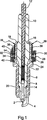
この図面には、スパークプラグに通常設けられている構成部分が示されている。このスパークプラグは、従来の形式の中心電極2と、接地電極4と、絶縁碍子6と、スパークプラグシェルとも呼ばれる外側ボディ8とを有している。 This drawing shows the components that are normally provided in a spark plug. This spark plug has a conventional type center electrode 2, a ground electrode 4, an insulator 6, and an outer body 8, also called a spark plug shell.
スパークプラグは、内燃機関の燃焼室内で火花を発生させるために設計されている。この火花は、上記の2つの電極の間で発生させられる。中心電極2は、絶縁碍子6の一方の端部の内側に取り付けられている。この中心電極2には、ロッド10を通じて高圧電流が供給される。このロッド10も、絶縁碍子6の内側に取り付けられていて、絶縁碍子6を貫通して、中心電極2とは反対側の端部から突出している。ロッド10の、中心電極2とは反対側の端部には、接続ナット(図示せず)を受容するためのねじ山12が設けられている。
Spark plugs are designed to generate sparks in the combustion chamber of an internal combustion engine. This spark is generated between the two electrodes. The center electrode 2 is attached to the inside of one end of the insulator 6. A high voltage current is supplied to the center electrode 2 through the
通常はセラミック材料から製作されている絶縁碍子6は、外側ボディ8の内側に取り付けられている。外側ボディ8は、概して円筒状かつ円形チューブの形を有している。外側ボディ8の一方の端部(以下、「下端部」と呼ぶ)は、接地電極4を支持している。接地電極4は、中心電極2と向かい合っている。 An insulator 6, usually made of a ceramic material, is attached to the inside of the outer body 8. The outer body 8 has a generally cylindrical and circular tube shape. One end of the outer body 8 (hereinafter referred to as “lower end”) supports the ground electrode 4. The ground electrode 4 faces the center electrode 2.
絶縁碍子6は、円錐状領域14により外側ボディ8内で位置決めされている。絶縁碍子6は圧着により外側ボディ8内に保持されている。外側ボディ8の上端部は絶縁碍子6のショルダ16に当て付けられており、これにより外側ボディ8の内側での絶縁碍子6の圧着部を形成している。圧着領域18はこのように、外側ボディ8の上端部に形成されており、これにより絶縁碍子6を外側ボディ8内に拘束しかつ円錐状領域14に載置させながら保持している。
The insulator 6 is positioned in the outer body 8 by the
通常の形式では、外側ボディ8の下端部の側方の外面には、ねじ山20が設けられている。このねじ山20の下に、プラグワッシャとも呼ばれるワッシャ(図示せず)を収容する凹所22が設けられている。
In a normal form, a
外側ボディ8は、凹所22の上方に拡大領域24を有しており、この拡大領域24は、スパークプラグをシリンダヘッドに螺入する際の当接部を形成する。拡大領域24の上部はショルダを有していて、このショルダ上に支持リング26が適応されている。支持リング26の半径方向の下面は、外側ボディ8の拡大領域24に載置されている。この支持リングの半径方向の上面28は、力センサ30のための支持部として働く。図示の実施例では、圧電素子32と、2つの電極34とを含む1つの圧電式センサが設けられており、2つの電極34は絶縁ワッシャ36により絶縁されている。
The outer body 8 has an enlarged
力センサ30には、支持された状態において、本実施例では支持ケーシング38により構成された支持エレメントによって予荷重がかけられている。支持ケーシング38は、外側ボディ8の上部の形状に適応するように成形されている。この支持ケーシング38は、力センサ30から圧着領域18にまで延びている。支持ケーシング38は、外側ボディ8に溶接されている。溶接された領域は、図面では矢印39により示されている。
In a supported state, the
したがって力センサ30は、外側ボディ8の拡大領域24(支持リング26を介して)と、支持ケーシング38との間に取り付けられている。したがって支持ケーシング38は、圧着領域18の近傍に溶接されており、力センサ30は、スパークプラグの、外側ボディ8の圧着領域18と拡大領域24との間の応力を測定する。
Accordingly, the
支持ケーシング38の上部区域、つまり力センサ30とは反対の側の円筒状の外面は、六角形の横断面を有している。上述のシリンダヘッドへのスパークプラグの螺入は、この支持ケーシング38において行われる。
The upper area of the
圧着領域18は、対応する燃焼室内で燃焼が起こると、上方に向かって押圧される。シリンダヘッドの近傍に配置されて該シリンダヘッドに螺入された拡大領域24は、押圧されないものと仮定される。外側ボディ8の拡大領域24と圧着領域18との間は、フレキシブルかつ変形可能な領域である。
When the combustion occurs in the corresponding combustion chamber, the crimping region 18 is pressed upward. It is assumed that the
力センサ30によって行われる測定は、力センサ30の信号を処理した後に、フレキシブルかつ変形可能な区域における応力を知ることを可能にする。その後の較正は、対応する内燃機関内の圧力を知ることを可能にする。
The measurements made by the
図面から判るように、電極34は、スパークプラグまで長手方向に延びた接続リード線40を有している。この接続リード線40はつまり、支持ケーシング38に対して平行に延びている。力センサ30を覆う外周キャップ42は、接続リード線40を外的損傷から保護している。この接続リード線40は好適には金属から製造されていて、力センサ30を電気ノイズから遮断することをも可能にする。
As can be seen from the drawing, the
本発明は、スパークプラグの大きな変更を要求することなく、従来の形式のスパークプラグに圧力センサを取り付けることを可能にするという利点を提供する。圧力センサ30は、スパークプラグの外側ボディ8の外周面に取り付けられている。このセンサの寸法は、半径方向および長手方向の寸法に関して著しく減じられている。さらに組み込まれる部品の数は、極めて限られている。さらにセンサの組立ても簡単である。実際には、種々多様な構成要素が、スパークプラグの外側ボディ8の上部の外周面に積み重ねられる。次いで較正された応力が支持ケーシング38に加えられ、これにより力センサ30に予荷重がかけられる。次いで応力が維持され、支持ケーシング38は融着される。
The present invention provides the advantage of allowing pressure sensors to be attached to conventional types of spark plugs without requiring major changes to the spark plug. The
このように取り付けられたこのタイプのセンサは、シリンダヘッドとスパークプラグのボディとの間に取り付けられた圧力センサよりも良好な信号を提供する。公知先行技術の場合、予荷重はスパークプラグをシリンダヘッドにねじ込む間に形成されていた。したがって一方では力センサに特定の応力をかけること、他方ではこの応力を長時間維持することは困難であった。 This type of sensor mounted in this way provides a better signal than a pressure sensor mounted between the cylinder head and the spark plug body. In the known prior art, the preload was formed while screwing the spark plug into the cylinder head. Therefore, it is difficult to apply a specific stress to the force sensor on the one hand and to maintain this stress for a long time on the other hand.
本発明は、非制限的な例として上に説明された好適な実施形態に限定されない。本発明は、当業者の範囲内における全ての様々な実施形態にも関連する。 The invention is not limited to the preferred embodiments described above as non-limiting examples. The invention also relates to all the various embodiments within the purview of those skilled in the art.
たとえば、使用される力センサは、上述のセンサとは異なるタイプの圧電式センサであってよい。たとえば、圧電抵抗式のセンサまたは他のタイプの力センサであってよい。 For example, the force sensor used may be a different type of piezoelectric sensor than that described above. For example, it may be a piezoresistive sensor or other type of force sensor.
上記の組立ては、1つの好適な組立てである。 The above assembly is one suitable assembly.
したがって力センサの下面とスパークプラグの外側ボディとの間に支持リングを設けることは、必須ではない。 Therefore, it is not essential to provide a support ring between the lower surface of the force sensor and the outer body of the spark plug.
支持ケーシングを、圧着領域の極めて近傍において溶接すると好適であるが、外側ボディへの支持ケーシングの溶接は、圧着領域からより離して実行することもできる。 Although it is preferred to weld the support casing in the immediate vicinity of the crimping area, the welding of the support casing to the outer body can also be carried out further away from the crimping area.
Claims (9)
該中心電極(2)を支持する絶縁碍子(6)と、
外側ボディ(8)と、
力センサ(30)と
が設けられているスパークプラグであって、
外側ボディ(8)の内側に絶縁碍子(6)が取り付けられており、外側ボディ(8)が、絶縁碍子(6)に圧着された領域(18)を有している形式のものにおいて、
力センサ(30)が、外側ボディ(8)の、前記圧着領域(18)に移行する第1の外周領域に取り付けられた支持エレメント(38)と、外側ボディ(8)の第2の外周領域(24)との間で、外側ボディ(8)の外周面に取り付けられており、
外側ボディ(8)の第2の外周領域(24)が、第1の外周領域よりも圧着領域(18)から離れており、
外側ボディ(8)が、第2の外周領域(24)の高さにおいて、外側ショルダ(28)を有しており、該ショルダ(28)に力センサ(30)の面が載置していて、
支持エレメント(38)に、力センサ(30)に向かって予荷重がかけられていることを特徴とするスパークプラグ。A center electrode (2);
An insulator (6) supporting the central electrode (2);
An outer body (8);
A spark plug provided with a force sensor (30),
In the type in which the insulator (6) is attached to the inside of the outer body (8), and the outer body (8) has a region (18) crimped to the insulator (6),
A force sensor (30) has a support element (38) attached to a first outer peripheral region of the outer body (8) that transitions to the crimping region (18), and a second outer peripheral region of the outer body (8). (24) is attached to the outer peripheral surface of the outer body (8),
The second outer peripheral region (24) of the outer body (8) is farther from the crimping region (18) than the first outer peripheral region;
The outer body (8) has an outer shoulder (28) at the height of the second outer peripheral region (24), and the surface of the force sensor (30) is placed on the shoulder (28). ,
The support element (38), spark plug, characterized in that preload toward the force sensor (30) is applied.
該中心電極(2)を支持する絶縁碍子(6)と、An insulator (6) supporting the central electrode (2);
外側ボディ(8)と、An outer body (8);
圧電式センサである力センサ(30)とA force sensor (30) which is a piezoelectric sensor;
が設けられているスパークプラグであって、A spark plug provided with
外側ボディ(8)の内側に絶縁碍子(6)が取り付けられており、外側ボディ(8)が、絶縁碍子(6)に圧着された領域(18)を有している形式のものにおいて、In the type in which the insulator (6) is attached to the inside of the outer body (8), and the outer body (8) has a region (18) crimped to the insulator (6),
前記圧着領域(18)が、外側ボディ(8)の上端部に形成されており、The crimping region (18) is formed at the upper end of the outer body (8);
力センサ(30)が、外側ボディ(8)の、前記圧着領域(18)に移行する第1の外周領域に取り付けられた支持エレメント(38)と、外側ボディ(8)の、第1の外周領域よりも圧着領域(18)から離れた第2の外周領域(24)との間で、外側ボディ(8)の外周面に取り付けられており、A force sensor (30) has a first outer periphery of the outer body (8) and a support element (38) attached to the first outer peripheral region of the outer body (8) that transitions to the crimping region (18). It is attached to the outer peripheral surface of the outer body (8) between the second outer peripheral region (24) farther from the crimping region (18) than the region,
外側ボディ(8)が、第2の外周領域(24)の高さにおいて、外側ショルダ(28)を有しており、該ショルダ(28)に力センサ(30)の面が載置していて、The outer body (8) has an outer shoulder (28) at the height of the second outer peripheral region (24), and the surface of the force sensor (30) is placed on the shoulder (28). ,
支持エレメント(38)に、力センサ(30)に向かって予荷重がかけられていることを特徴とするスパークプラグ。A spark plug characterized in that a preload is applied to the support element (38) towards the force sensor (30).
Applications Claiming Priority (3)
| Application Number | Priority Date | Filing Date | Title |
|---|---|---|---|
| FR0606195 | 2006-07-07 | ||
| FR0606195A FR2903531B1 (en) | 2006-07-07 | 2006-07-07 | IGNITION CANDLE INTEGRATING PRESSURE SENSOR |
| PCT/FR2007/001085 WO2008003846A1 (en) | 2006-07-07 | 2007-06-28 | Spark plug incorporating a pressure sensor |
Publications (2)
| Publication Number | Publication Date |
|---|---|
| JP2009543310A JP2009543310A (en) | 2009-12-03 |
| JP5114480B2 true JP5114480B2 (en) | 2013-01-09 |
Family
ID=37776673
Family Applications (1)
| Application Number | Title | Priority Date | Filing Date |
|---|---|---|---|
| JP2009518914A Expired - Fee Related JP5114480B2 (en) | 2006-07-07 | 2007-06-28 | Spark plug with built-in pressure sensor |
Country Status (9)
| Country | Link |
|---|---|
| US (1) | US8196459B2 (en) |
| EP (1) | EP2038973B1 (en) |
| JP (1) | JP5114480B2 (en) |
| KR (1) | KR20090034366A (en) |
| CN (1) | CN101496244B (en) |
| AT (1) | ATE468641T1 (en) |
| DE (1) | DE602007006668D1 (en) |
| FR (1) | FR2903531B1 (en) |
| WO (1) | WO2008003846A1 (en) |
Families Citing this family (8)
| Publication number | Priority date | Publication date | Assignee | Title |
|---|---|---|---|---|
| FR2923093A1 (en) | 2007-10-29 | 2009-05-01 | Continental Automotive France | SPARK IGNITION DEVICE WITH INTEGRATED COMBUSTION SENSOR |
| US8578762B2 (en) | 2009-01-29 | 2013-11-12 | Federal-Mogul Ignition Company | Spark plug with integral combustion sensor and engine component therewith |
| CN102341979A (en) | 2009-01-29 | 2012-02-01 | 费德罗-莫格尔点火公司 | Spark plug with combustion sensor |
| EP2690726B1 (en) | 2012-07-25 | 2017-10-18 | Caterpillar Energy Solutions GmbH | Spark plug |
| EP2730905B1 (en) * | 2012-11-12 | 2019-01-02 | Sensata Technologies, Inc. | A pressure-measuring plug for a combustion engine |
| WO2014178449A1 (en) * | 2013-04-30 | 2014-11-06 | 쌍용자동차 주식회사 | Ignition plug with oxygen sensor |
| FR3024542B1 (en) * | 2014-07-31 | 2016-09-02 | Continental Automotive France | SUPPORT OF AN ELECTRONIC MODULE OF A PRESSURE MEASURING SENSOR |
| US9702333B1 (en) * | 2016-03-29 | 2017-07-11 | Eco-S Spark Plug Corporation | Thermally controlled ignition device |
Family Cites Families (16)
| Publication number | Priority date | Publication date | Assignee | Title |
|---|---|---|---|---|
| JPH0412488A (en) * | 1990-05-01 | 1992-01-17 | Ngk Spark Plug Co Ltd | Spark plug with pressure sensor |
| JP3141218B2 (en) * | 1992-07-28 | 2001-03-05 | 日本特殊陶業株式会社 | Spark plug with built-in pressure sensor |
| JP3806448B2 (en) * | 1993-02-03 | 2006-08-09 | 日本特殊陶業株式会社 | Spark plug |
| US6204594B1 (en) * | 1998-06-12 | 2001-03-20 | Cooper Automotive Products, Inc. | Spark plug with pressure sensor |
| US6119667A (en) * | 1999-07-22 | 2000-09-19 | Delphi Technologies, Inc. | Integrated spark plug ignition coil with pressure sensor for an internal combustion engine |
| FR2797721B1 (en) * | 1999-08-18 | 2001-10-19 | Daniel Drecq | SPARK PLUG PROVIDED WITH A PRESSURE SENSOR, AND THERMAL ENGINE PROVIDED WITH SUCH SPARK PLUGS |
| JP4378040B2 (en) * | 2000-07-31 | 2009-12-02 | 日本特殊陶業株式会社 | Spark plug and plug cap with built-in pressure sensor |
| JP2002124362A (en) * | 2000-10-19 | 2002-04-26 | Ngk Spark Plug Co Ltd | Pressure sensor built-in spark plug |
| US6799451B2 (en) * | 2001-03-05 | 2004-10-05 | Delphi Technologies, Inc. | Spark generating apparatus having strain gage cylinder pressure measurement feature |
| JP2003077620A (en) * | 2001-06-20 | 2003-03-14 | Denso Corp | Spark plug and its manufacturing method |
| JP3900053B2 (en) * | 2002-09-19 | 2007-04-04 | 株式会社デンソー | Ignition device for internal combustion engine |
| JP4308697B2 (en) * | 2004-03-31 | 2009-08-05 | 本田技研工業株式会社 | In-cylinder pressure detector |
| JP4209829B2 (en) * | 2004-10-15 | 2009-01-14 | 三菱電機株式会社 | Knock sensor and manufacturing method thereof |
| US7272970B2 (en) * | 2005-03-31 | 2007-09-25 | Ngk Spark Plug Co., Ltd. | Spark plug having combustion pressure detecting function |
| FR2923093A1 (en) * | 2007-10-29 | 2009-05-01 | Continental Automotive France | SPARK IGNITION DEVICE WITH INTEGRATED COMBUSTION SENSOR |
| US8707922B2 (en) * | 2009-12-15 | 2014-04-29 | Federal Mogul Ignition Company | Spark ignition device for an internal combustion engine and central electrode assembly therefor |
-
2006
- 2006-07-07 FR FR0606195A patent/FR2903531B1/en not_active Expired - Fee Related
-
2007
- 2007-06-28 EP EP07803794A patent/EP2038973B1/en not_active Not-in-force
- 2007-06-28 DE DE602007006668T patent/DE602007006668D1/en active Active
- 2007-06-28 KR KR1020097002007A patent/KR20090034366A/en active IP Right Grant
- 2007-06-28 JP JP2009518914A patent/JP5114480B2/en not_active Expired - Fee Related
- 2007-06-28 AT AT07803794T patent/ATE468641T1/en not_active IP Right Cessation
- 2007-06-28 CN CN2007800257678A patent/CN101496244B/en not_active Expired - Fee Related
- 2007-06-28 WO PCT/FR2007/001085 patent/WO2008003846A1/en active Application Filing
- 2007-06-28 US US12/307,841 patent/US8196459B2/en not_active Expired - Fee Related
Also Published As
| Publication number | Publication date |
|---|---|
| US8196459B2 (en) | 2012-06-12 |
| EP2038973A1 (en) | 2009-03-25 |
| US20100116039A1 (en) | 2010-05-13 |
| ATE468641T1 (en) | 2010-06-15 |
| FR2903531A1 (en) | 2008-01-11 |
| FR2903531B1 (en) | 2008-09-26 |
| KR20090034366A (en) | 2009-04-07 |
| WO2008003846A1 (en) | 2008-01-10 |
| CN101496244A (en) | 2009-07-29 |
| CN101496244B (en) | 2012-05-30 |
| EP2038973B1 (en) | 2010-05-19 |
| DE602007006668D1 (en) | 2010-07-01 |
| JP2009543310A (en) | 2009-12-03 |
Similar Documents
| Publication | Publication Date | Title |
|---|---|---|
| JP5114480B2 (en) | Spark plug with built-in pressure sensor | |
| US6539787B1 (en) | Glow plug having a combustion pressure sensor | |
| US9063031B2 (en) | Pressure-measuring plug for a combustion engine | |
| US7726269B2 (en) | Glow plug with integrated pressure sensor | |
| US6973820B2 (en) | Combustion pressure sensor designed to ensure stability of output characteristic and sensitivity | |
| US9581565B2 (en) | Gas sensor | |
| JPH03293534A (en) | Mounting apparatus for pressure sensor | |
| US6597088B1 (en) | Spark plug with pressure measuring device | |
| KR20070043931A (en) | Glow plug provided with a pressure sensor | |
| JP3900059B2 (en) | Mounting structure and mounting method of glow plug with combustion sensor and glow plug with combustion pressure sensor | |
| KR101614625B1 (en) | Glow plug equipped with pressure sensor | |
| US6538366B1 (en) | Sparking plug equipped with a pressure sensor, and combustion engine equipped with such sparking plugs | |
| US20060123887A1 (en) | Apparatus for pressure detection in an engine combustion chamber | |
| US20110056925A1 (en) | Pressure Measuring Glow Plug | |
| KR101218081B1 (en) | Body of a glow plug provided with a pressure sensor | |
| WO2014010246A1 (en) | Combustion sensor | |
| JP4207070B2 (en) | Glow plug with combustion sensor | |
| KR20120117844A (en) | Ignition and pressure measurement device of an internal combustion engine | |
| JP4206941B2 (en) | Combustion pressure sensor | |
| JP5237237B2 (en) | Spark plug | |
| JPH0127586Y2 (en) |
Legal Events
| Date | Code | Title | Description |
|---|---|---|---|
| A621 | Written request for application examination |
Free format text: JAPANESE INTERMEDIATE CODE: A621 Effective date: 20100510 |
|
| RD04 | Notification of resignation of power of attorney |
Free format text: JAPANESE INTERMEDIATE CODE: A7424 Effective date: 20101227 Free format text: JAPANESE INTERMEDIATE CODE: A7424 Effective date: 20101228 |
|
| A977 | Report on retrieval |
Free format text: JAPANESE INTERMEDIATE CODE: A971007 Effective date: 20120216 |
|
| A131 | Notification of reasons for refusal |
Free format text: JAPANESE INTERMEDIATE CODE: A131 Effective date: 20120224 |
|
| A601 | Written request for extension of time |
Free format text: JAPANESE INTERMEDIATE CODE: A601 Effective date: 20120518 |
|
| A602 | Written permission of extension of time |
Free format text: JAPANESE INTERMEDIATE CODE: A602 Effective date: 20120525 |
|
| A601 | Written request for extension of time |
Free format text: JAPANESE INTERMEDIATE CODE: A601 Effective date: 20120625 |
|
| A602 | Written permission of extension of time |
Free format text: JAPANESE INTERMEDIATE CODE: A602 Effective date: 20120702 |
|
| A601 | Written request for extension of time |
Free format text: JAPANESE INTERMEDIATE CODE: A601 Effective date: 20120724 |
|
| A602 | Written permission of extension of time |
Free format text: JAPANESE INTERMEDIATE CODE: A602 Effective date: 20120731 |
|
| A521 | Request for written amendment filed |
Free format text: JAPANESE INTERMEDIATE CODE: A523 Effective date: 20120824 |
|
| TRDD | Decision of grant or rejection written | ||
| A01 | Written decision to grant a patent or to grant a registration (utility model) |
Free format text: JAPANESE INTERMEDIATE CODE: A01 Effective date: 20120928 |
|
| A01 | Written decision to grant a patent or to grant a registration (utility model) |
Free format text: JAPANESE INTERMEDIATE CODE: A01 |
|
| A61 | First payment of annual fees (during grant procedure) |
Free format text: JAPANESE INTERMEDIATE CODE: A61 Effective date: 20121015 |
|
| FPAY | Renewal fee payment (event date is renewal date of database) |
Free format text: PAYMENT UNTIL: 20151019 Year of fee payment: 3 |
|
| R150 | Certificate of patent or registration of utility model |
Free format text: JAPANESE INTERMEDIATE CODE: R150 |
|
| LAPS | Cancellation because of no payment of annual fees |