JP5114440B2 - Subsoil improvement work machine - Google Patents
Subsoil improvement work machine Download PDFInfo
- Publication number
- JP5114440B2 JP5114440B2 JP2009036550A JP2009036550A JP5114440B2 JP 5114440 B2 JP5114440 B2 JP 5114440B2 JP 2009036550 A JP2009036550 A JP 2009036550A JP 2009036550 A JP2009036550 A JP 2009036550A JP 5114440 B2 JP5114440 B2 JP 5114440B2
- Authority
- JP
- Japan
- Prior art keywords
- subsoil
- hydrophobic material
- tank
- working machine
- plow
- Prior art date
- Legal status (The legal status is an assumption and is not a legal conclusion. Google has not performed a legal analysis and makes no representation as to the accuracy of the status listed.)
- Active
Links
Images


Landscapes
- Soil Working Implements (AREA)
- Agricultural Machines (AREA)
Description
本発明は、重粘土の心土層を改良する心土改良用作業機に関するものである。 The present invention relates to a working machine for improving the subsoil of a heavy clay.
重粘土地帯の畑地、草地等の圃場は、作土層の下にある心土層が通常粘土であって、そこをトラクター等の走行により圧縮されて強固な底盤を形成しているため、一般の圃場に比べて通気性、透水性、保水性等の土壌物性が低く、農産物、花等の生産性が低い。このような重粘土の心土層(以下、心土ともいう)を改良するための方法およびそのために用いられる作業機としては、例えば特許文献1に記載されている心土改良法および心土改良用作業機が知られている。
In fields such as upland and grassland in the heavy clay zone, the subsoil layer under the soil layer is usually clay, and it is compressed by the running of a tractor etc. to form a solid bottom. Compared with other fields, soil physical properties such as air permeability, water permeability and water retention are low, and productivity of agricultural products and flowers is low. As a method for improving such a heavy clay subsoil layer (hereinafter also referred to as subsoil) and a working machine used therefor, for example, the subsoil improvement method and subsoil improvement described in
前記特許文献1に記載されている心土改良用作業機は、プラウによって作土層(以下、作土ともいう)を耕起(掘削)して一列目の心土層を露呈させ、り柱(犂)によって前記心土層に溝を掘削し、この溝に疎水材を投入し、しかる後チゼルで溝の周囲の心土をかき崩して溝幅を拡幅するとともに溝に投入された疎水材とかき崩した心土とをほぐして混和させる(膨軟化)。次に、作業機が一列目の心土層の隣に移動してプラウが新たに二列目の作土層を耕起すると、その作土で直前に耕起した一列目の心土層および溝を覆土、すなわち耕起した作土を覆い被せて作土層から露呈している心土層を元に戻すようにしている。
The working machine for improving subsoil described in
しかしながら、上記した従来の心土改良用作業機は、疎水材を溝に均等に投入することができず、疎水材の散布性能が低いという問題があった。すなわち、タンク内の疎水材を後方送出しコンベヤによって後方に搬送して横送りコンベヤに投下したとき、後方送出しコンベヤと横送りコンベヤとは互いに直交して配設されているため、疎水材は横送りコンベア上の幅方向において一箇所に集中的に投下されて堆積する。言い換えれば、横送りコンベアの幅方向に均等に振り分けられて投下されないため、横送りコンベアから溝に投入される疎水材は溝の長手方向においてばらつきが生じる。また、タンク内の疎水材を後方送出しコンベアによって搬送すると、後方送出しコンベア上に載っている最下層の疎水材のみが搬送されて上層部の疎水材は搬送されず、タンクの左右両側壁間に疎水材のブリッジを形成し、後方送出しコンベアによる疎水材の搬送量にばらつきが生じる。 However, the above-described conventional subsoil improvement work machine has a problem that the hydrophobic material cannot be uniformly introduced into the groove, and the dispersion performance of the hydrophobic material is low. That is, when the hydrophobic material in the tank is fed backward and conveyed backward by the conveyor and dropped onto the cross feed conveyor, the rear feed conveyor and the cross feed conveyor are arranged orthogonal to each other. It is dropped and accumulated in one place in the width direction on the transverse conveyor. In other words, since it is not evenly distributed and dropped in the width direction of the transverse feed conveyor, the hydrophobic material thrown into the groove from the transverse feed conveyor varies in the longitudinal direction of the groove. In addition, when the hydrophobic material in the tank is fed backward and conveyed by the conveyor, only the lowermost hydrophobic material placed on the backward fed conveyor is conveyed, and the upper hydrophobic material is not conveyed. Hydrophobic material bridges are formed between them, and the transport amount of the hydrophobic material by the backward delivery conveyor varies.
そこで、このような疎水材の搬送量のばらつきを少なくするために、従来は作業者が手作業でタンク内に生じる疎水材のブリッジを棒等の適宜な道具で突き壊したり、横送りコンベア上に投下された疎水材を掻き出してコンベアの幅方向に均等になるように振り分けていた。 Therefore, in order to reduce such a variation in the transport amount of the hydrophobic material, conventionally, an operator manually breaks the bridge of the hydrophobic material generated in the tank with an appropriate tool such as a bar, The hydrophobic material dropped onto the conveyor was scraped out and distributed evenly in the width direction of the conveyor.
しかしながら、このような作業者による疎水材の掻き出しおよびブリッジの壊し作業は、心土改良用作業機をトラクターで牽引走行させ、心土改良作業を行っている状態で行なうために、2人の作業者、すなわちトラクターを運転する作業者と、疎水材の掻き出しおよびブリッジの壊し作業を行う作業者を必要とし、またトラクターを運転する作業者においては疎水材の掻き出しおよびブリッジの壊し作業を行う作業者のために慎重な運転と十分な安全性の確認と確保が要求されるため、精神的な負担が多く、疎水材の掻き出しおよびブリッジの壊し作業を行う作業者においては肉体的な負担が大きいという問題があった。 However, since the hydrophobic material scraping and the bridge breaking work by such an operator are performed while the subsoil improvement work machine is towed by the tractor and the subsoil improvement work is being performed, the work of two people A worker who operates the tractor and a worker who scrapes the hydrophobic material and breaks the bridge, and a worker who drives the tractor and scrapes the hydrophobic material and breaks the bridge Therefore, careful driving and sufficient safety confirmation and ensuring are required, so there is a lot of mental burden, and there is a heavy physical burden on workers who scrape hydrophobic materials and break bridges There was a problem.
本発明は、上記した従来の問題を解決するためになされたもので、その目的とするところは、作業者による疎水材の掻き出しおよびブリッジの壊し作業を必要とせず、圃場を走行するだけで疎水材の溝への投入量を一定にすることができ、省力化を可能にするとともに疎水材の散布性能を向上させるようにした心土改良用作業機を提供することにある。 The present invention has been made in order to solve the above-described conventional problems. The object of the present invention is to eliminate the need for the operator to scrape the hydrophobic material and break the bridge. An object of the present invention is to provide a working machine for improving the subsoil, which can make the input amount of the material into the groove constant, can save labor and improve the dispersion performance of the hydrophobic material.
上記目的を達成するために本発明に係る心土改良用作業機は、タイヤ付き機体と、前記機体上に設置された疎水材を収納するタンクと、前記タンクの内底部に配設され前記疎水材を前方から後方に搬送して前記タンクの後方開口部より外部に排出する後方送出しコンベアと、前記タンクの後方開口部より排出された前記疎水材を前記機体の一側に向けて搬送する横送りコンベアと、前記機体の下方に配設され作土層を耕起して心土層を露呈させるプラウと、前記プラウの後方に位置して前記機体の下方に昇降自在に配設され、前記心土層に溝を掘削するり柱と、前記タンクの後方開口部から前記横送りコンベア上に投下された前記疎水材を前記横送りコンベアの搬送方向と直交する方向に掻き出して分散させる疎水材掻き出し調整装置とを備えているものである。 In order to achieve the above object, a working machine for improving subsoil according to the present invention includes a machine body with a tire, a tank for storing a hydrophobic material installed on the machine body, and an inner bottom portion of the tank. Conveying material from the front to the rear and discharging it from the rear opening of the tank to the outside, and conveying the hydrophobic material discharged from the rear opening of the tank toward one side of the machine body A transverse conveyor, a plow disposed below the machine body to cultivate a soil layer to expose the subsoil layer, and disposed rearward of the plow so as to be movable up and down below the machine body, Hydrophobic that scrapes and disperses the pillars excavating grooves in the subsoil layer and the hydrophobic material dropped on the transverse feed conveyor from the rear opening of the tank in a direction perpendicular to the conveying direction of the transverse feed conveyor Equipped with a material scraping adjustment device And those are.
また、本発明に係る心土改良用作業機は、上記発明において、前記疎水材掻き出し調整装置および前記横送りコンベアを連動させるものである。 Moreover, the working machine for subsoil improvement which concerns on this invention makes the said hydrophobic material scraping adjustment apparatus and the said horizontal feed conveyor interlock | cooperate in the said invention.
また、本発明に係る心土改良用作業機は、前記タンクの内部上方に設けられ、前記タンク内の疎水材を掻き出す後方掻き出し装置を備えているものである。 Moreover, the working machine for improving subsoil according to the present invention includes a rear scraping device that is provided in the upper part of the tank and scrapes the hydrophobic material in the tank.
また、本発明に係る心土改良用作業機は、前記疎水材掻き出し調整装置が、回転軸の外周にその軸線方向に離間して設けられた複数の掻き出し用フィンを有するフィンローラからなるものである。 In the subsoil improvement work machine according to the present invention, the hydrophobic material scraping adjusting device includes a fin roller having a plurality of scraping fins provided on the outer periphery of the rotating shaft so as to be spaced apart from each other in the axial direction. is there.
また、本発明に係る心土改良用作業機は、前記タンクの後方開口部を開閉する油圧式シャッタを備えたものである。 The subsoil improvement work machine according to the present invention includes a hydraulic shutter that opens and closes the rear opening of the tank.
また、本発明に係る心土改良用作業機は、前記プラウを機体の左右方向にずらして前後方向に少なくとも2つ縦設したものである。 Moreover, the working machine for improving subsoil according to the present invention is such that at least two plows are vertically arranged in the front-rear direction by shifting in the left-right direction of the machine body.
さらに、本発明に係る心土改良用作業機は、前記溝を保護するとともに前記横送りコンベアから投下された疎水材を前記溝に投入するオープナーを前記り柱に設けたものである。 Furthermore, the working machine for improving the subsoil according to the present invention is provided with an opener on the column that protects the groove and introduces a hydrophobic material dropped from the transverse conveyor into the groove.
本発明においては、後方送出しコンベアから横送りコンベア上に投下された疎水材を疎水材掻き出し調整装置によって、横送りコンベアの走行方向と直交する方向に掻き出して分散させるため、横送りコンベアの幅方向において疎水材の量を均一化させることができる。したがって、作業者による疎水材の掻き出し作業を必要とせず、省力化することができ、また疎水材を溝に一定量投入することができるから、疎水材の散布性能を向上させることができる。 In the present invention, the hydrophobic material dropped onto the lateral feed conveyor from the rear delivery conveyor is scraped and dispersed in the direction orthogonal to the traveling direction of the lateral feed conveyor by the hydrophobic material scraping adjustment device. The amount of hydrophobic material can be made uniform in the direction. Therefore, the operator does not need to scrape off the hydrophobic material and can save labor, and a certain amount of the hydrophobic material can be put into the groove, so that the dispersion performance of the hydrophobic material can be improved.
疎水材掻き出し調整装置および横送りコンベアが連動して稼働する発明においては、疎水材を溝に連続して確実に投入、散布することができ、また横送りコンベアの連駆動装置を疎水材掻き出し調整装置に兼用することができる。 In the invention in which the hydrophobic material scraping adjustment device and the transverse feed conveyor operate in conjunction with each other, the hydrophobic material can be continuously put into and dispersed in the groove, and the continuous drive device of the transverse feed conveyor can be adjusted with the hydrophobic material scraping adjustment. It can also be used as a device.
後方掻き出し装置を備えた発明においては、タンク内の内部上方の疎水材を掻き出すため、タンク内に疎水材のブリッジが生じず、したがって、作業者によるブリッジの壊し作業を必要とせず、後方送出しコンベアによって疎水材を一定量搬送することができるから、散布性能を向上させることができる。 In the invention provided with the rear scraping device, the hydrophobic material above the inside of the tank is scraped out, so that no bridge of the hydrophobic material is generated in the tank. Since a certain amount of the hydrophobic material can be conveyed by the conveyor, the spraying performance can be improved.
疎水材掻き出し調整装置が複数の掻き出し用フィンを有するフィンローラからなる発明においては、フィンローラが疎水材を掻き出してほぐすため、あらゆる疎水材に対応することができる。 In the invention in which the hydrophobic material scraping adjusting device includes a fin roller having a plurality of fins for scraping, the fin roller scrapes and loosens the hydrophobic material, and therefore can cope with any hydrophobic material.
油圧式シャッタを備えた発明においては、運転席からの遠隔操作によってシャッタを開閉制御することができ、タンクの後方開口部の開度調整を迅速に行なうことができる。また、疎水材をタンクに収納するとき、シャッタによってタンクの後方開口部を閉じておくことにより、疎水材が後方開口部からこぼれ出るのを防止することができる。 In the invention provided with the hydraulic shutter, the shutter can be controlled to be opened and closed by remote control from the driver's seat, and the opening degree of the rear opening of the tank can be adjusted quickly. Further, when the hydrophobic material is stored in the tank, the hydrophobic material can be prevented from spilling out from the rear opening by closing the rear opening of the tank with the shutter.
プラウを少なくとも2つ縦設した発明においては、各プラウが作土を分担して耕起するため作土を幅広く耕起することができ、また、各プラウに対する作土の抵抗を小さくすることができる。 In the invention in which at least two plows are installed vertically, each plow shares the soil and cultivates it, so that the soil can be cultivated widely, and the resistance of the soil to each plow can be reduced. it can.
り柱にオープナーを設けた発明においては、り柱によって形成された溝をオープナーが保護し、溝壁の崩壊を防止することができる。また、横送りコンベアから投下された疎水材を前記溝に投入することができる。 In the invention in which the opener is provided in the column, the opener can protect the groove formed by the column and prevent the groove wall from collapsing. Moreover, the hydrophobic material dropped from the transverse feed conveyor can be thrown into the groove.
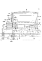
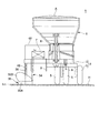
図1〜図3において、全体を符号1で示す心土改良用作業機は、重粘土地帯の畑地、草地などの圃場Hに疎水材Aを投入、散布して心土改良するもので、図示していないトラクターに牽引されて走行する機体2を備えている。機体2は、前後方向に長い矩形枠状のフレーム3と、このフレーム3の下方に上下動自在に取付けられ、油圧シリンダ4によって昇降する3本のタイヤ5とを備え、フレーム3上に疎水材Aを収納するタンク6と油圧タンク7が設置され、前端にはトラクターに接続されるトップリンク8およびロアリンク9が取付けられている。油圧シリンダ4は、心土改良用作業機1の非作業時においてタイヤ5を図1に2点鎖線で示す最下位置に下降させて機体2を保持し、作業時において破線で示す最上位置に機体2を上昇させて保持する。
1 to 3, the subsoil improvement work machine indicated by
前記圃場Hは、表層部が厚さ25〜30cm程度の作土層Bを形成し、その下層が粘土からなる心土層Cを形成している。 In the field H, a soil layer B having a surface layer portion of about 25 to 30 cm in thickness is formed, and a subsoil layer C made of clay is formed in the lower layer.
疎水材Aとしては、有機質の堆肥(例えば、バーク堆肥)、砂、貝殻、チップ等が用いられる。 As the hydrophobic material A, organic compost (for example, bark compost), sand, shells, chips and the like are used.
前記タンク6は、上方が開放する前後方向に長い箱型ではあるが、下部が上方に向かって広がる逆台形で、上部が矩形の箱型に形成されており、内底面に疎水材Aを前方から後方に向かって搬送する後方送出しコンベア10が配設され、背面下部には後方開口部11が形成されている。後方送出しコンベア10は、ベルトコンベアからなり、タンク6の底部と略同じ長さおよび幅を有している。後方開口部11は後方送出しコンベア10に対応して形成され、油圧式シャッタ12によって開閉される。油圧式シャッタ12は、作業者がトラクターの運転席においてスイッチを操作して油圧シリンダ12Aを駆動することにより開閉制御される。さらに、タンク6の内部後方でかつ上方には、タンク6の内部上方で後方寄りに収納されている疎水材Aを掻き出す後方掻き出し装置13が配設されている。
Although the
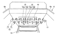
図3、図6〜図8において、前記後方掻き出し装置13は、タンク6の左右両側壁6a、6b間に回転自在に支架された駆動軸14と、この駆動軸14に取付けられた多数の掻き出し用羽根15と、前記駆動軸14を図6、図7において矢印17で示す掻き出し方向に回転させる図示していないのモータとを備えている。掻き出し用羽根15は、駆動軸14の軸線方向に一定の間隔をおいて取付けられた細長い矩形板状の羽根からなり、2枚一組で駆動軸14の軸線方向に配列されている。また、2枚一組の掻き出し用羽根15a、15bは、駆動軸14の周方向に180°位相をずらして取付けられ、かつ駆動軸14の軸線に対して傾斜するように所要の取付角度α(例えば、α=60°:図7)をもって取付けられている。さらに駆動軸14の軸線方向において隣り合う2枚一組の羽根15a、15bどうしは、互いに直交するように駆動軸14の周方向に90°位相をずらして取付けられている。
3 and 6 to 8, the
図1、図3〜図6において、前記機体2の後部には、後方送出しコンベア10によって搬送されタンク6の後方開口部11から投下された疎水材Aを疎水材投下部20に搬送する横送りコンベア21が配設されている。横送りコンベア21は、ベルトコンベアからなり、後方送出しコンベア10と直交するように配設され、疎水材Aを機体2の後端右端に搬送する。疎水材投下部20は、機体2の後端右端で、前記横送りコンベア21の終端直下とされる。また、横送りコンベア21の上方で終端近傍部には、後方送出しコンベア10から横送りコンベア21上に投下された疎水材Aを横送りコンベア21の搬送方向と直交する方向、言い換えれば機体2の前後方向に掻き出して均一に分散させる疎水材掻き出し調整装置22が配設されている。
In FIG. 1 and FIG. 3 to FIG. 6, the rear side of the
疎水材掻き出し調整装置22は、横送りコンベア21の前後壁25a、25b間に回転自在に支架された回転軸26と、この回転軸26の外周にその軸線方向に所定の間隔をおいて取付けられた複数の掻き出し用フィン27とからなるフィンローラによって構成されている。このような疎水材掻き出し調整装置22は、横送りコンベア21の駆動軸28を駆動するモータ29の回転がチェーン30を介して伝達されることにより、疎水材Aの投下、散布時に横送りコンベア21と連動して稼働し、これによってモータ29に疎水材掻き出し調整装置22の駆動装置を兼用させている。
The hydrophobic material
図1、図4、図6および図9において、前記機体2の下方右側には、さらにコルター34、プラウ(鍬)35およびり柱36が配設されている。前記コルター34は、心土改良用作業機1の前進走行にともない圃場Hの残渣物を切断するために用いられるもので、円盤状に形成され機体2の右前端下方に回転自在、かつばね等の緩衝装置(図示せず)によって上下動可能および左右方向に傾動可能に配設されている。
In FIG. 1, FIG. 4, FIG. 6 and FIG. 9, a
前記プラウ35は、作土層Bを耕起して心土層Cを露呈させるもので、前記コルター34の直後でその右側であって、かつコルター34よりも下方で、非作業時における最下位置のタイヤ5より若干上方に位置するように配設されている。また、プラウ35は、作土Bを耕起し進行方向右側に反転させ得る形状と傾斜角度をもつように形成されている。すなわち、プラウ35は、作土Bを耕起する右斜め後方に傾斜した耕起部35Aと、この耕起部35Aの上方に張り出しており耕起部35Aによって耕起された作土Bを反転させる蝶の羽根形をした反転部35Bとを一体に有している。プラウ35の機体中心軸線に対する傾斜角度βは、略40°である(図3)。
The
前記り柱36は、プラウ35による作土層Bの耕起によって露呈した心土層Cの表面に疎水材Aを投入、散布するための溝40(図11)を掘削するものであって、前記プラウ35の直後に昇降自在に配設され、油圧シリンダ41によって昇降されるように構成されている。また、り柱36は、プラウ35の幅W(図3)より十分小さい幅を有して、プラウ35の略幅方向中心線上に位置するように配設されている。油圧シリンダ41は、心土改良用作業機1の非作業時において、図1に実線で示すようにり柱36をプラウ35と略同一高さになるように最上位置に上昇させて保持し、心土改良作業時にり柱36を二点鎖線で示すプラウ35よりも所定距離、例えば30cm程度下方の最下位置に下降させて保持する。なお、図1において、G.Lは地表面、P.Lはプラウ35の下端レベル、Q.Lはり柱36によって掘削される溝40の底部レベルを示す。
The
図1、図3〜図6および図9において、り柱36の背後には、金属板によって形成された上下および後方に開放する平面視略U字状のオープナー45が取付けられている。オープナー45は、り柱36によって掘削した溝40を保護し、溝壁の崩壊を防止する機能と、横送りコンベア21から投下された疎水材Aを前記溝40に投入する機能とを有するもので、前記疎水材投入部20の真下に位置するようにり柱36の支柱36Aに取付けられている。また、オープナー45は、横送りコンベア21の幅より長く形成され後端が横送りコンベア21より後方に延在しており、り柱36によって掘削される溝40より十分に高く形成され下端前端部がり柱36の下端と略同一高さで、下端後端部に切欠部46が設けられ、上方開口部には前記横送りコンベア21から投下された疎水材Aをオープナー45に導くガイド部材47(図5、図9)の下端部が挿入されている。さらに、オープナー45は、り柱36の幅より大きな幅にすることにより、溝40を拡幅する機能をも有している。ガイド部材47は、ゴム等の弾性材料によって断面形状が扁平な長円形の筒体に形成され、横送りコンベア21の上方を覆うカバー48に取付けられている。
1, FIG. 3 to FIG. 6 and FIG. 9, an
次に、上記構造からなる心土改良用作業機1による心土改良作業について説明する。
図1において、心土改良用作業機1は、タンク6に疎水材Aを収納した後、トラクターT(図10)に連結されて所定の圃場Hに搬送される。圃場Hへの輸送に際しては、タイヤ5を油圧シリンダ4によってプラウ35の下端より若干低い最下位置まで下降させて保持し、り柱36を油圧シリンダ41によって最上位置まで上昇させる。これにより、心土改良用作業機1の輸送時においては、タイヤ5のみが路面に接地して機体2を支持するため、プラウ35とり柱36が路面を耕起してしまうようなことがなく、プラウ35またはり柱36の破損を防止することができる。
Next, the subsoil improvement work by the subsoil
In FIG. 1, the subsoil
心土改良用作業機1による耕起の種類としては、a.耕地を往復しながら耕起する往復耕法、b.耕地を回りながら耕起する回り耕法、c.耕地を往路のみ耕起する片道耕法、d.耕地全体を蛇行しながら耕起して順次同一方向に礫土を反転させる順次耕法の4種類が知られている。本実施の形態においては、図10に示す外返し耕による往復耕法によって耕起する例を示す。すなわち、外返し耕による往復耕法は、心土改良用作業機1が耕地(圃場H)の両側から耕起部49の中央に徐々に向かうように往復走行しながら耕起部49を耕起して礫土を外側(進行方向右側)に反転させ、複数条の溝40を所定のピッチで掘削する耕法である。
The types of tillage by the subsoil
圃場Hの左右両端部は、トラクタTの旋回、移動部分を形成し、耕起部49の心土改良時においては心土改良用作業機1によって心土改良しない通称枕地と呼ばれる非耕起部50、51(図10の斜線部)を形成している。これらの非耕起部50、51は、トラクターTと心土改良用作業機1の総全長(10m程度)と略等しく、この部分については、耕起部49の心土改良作業が終了した後に、心土改良用作業機1によって片道耕法で作土層Bおよび溝40の掘削を行ない、疎水材Aの投入、散布、およびその後の作土による覆土を行なう。
The left and right ends of the farm field H form a turning and moving part of the tractor T, and when the subsoil is improved by the plowing
トラクターTは、心土改良用作業機1を牽引して圃場Hに到着すると、図10において例えば右側非耕起部50の右端に心土改良用作業機1を停止させて作業開始位置Gとする。次に、油圧シリンダ4によってタイヤ5を最上位置に上昇させて機体2を相対的に下降させ、プラウ35を右側非耕起部50の予め掘削しておいた心土層Cの表面に接触させる。さらに、油圧シリンダ41によってり柱36を最下位置に下降させてり柱36とオープナー45の下端部を前記心土層Cの表面に予め形成しておいた溝に挿入する。タイヤ5の上昇にともない機体2を下降させると、コルター34は、図1に示すように心土改良用作業機1全体の重量により下端部が作土層Bに押し込まれる。
When the tractor T pulls the subsoil
心土改良用作業機1による心土改良作業の準備が完了すると、作業者はトラクターTを前進走行させて心土改良用作業機1による心土改良作業を開始する。トラクターTの走行開始と同時に、後方送出しコンベア10、後方掻き出し装置13および横送りコンベア21の電源スイッチを投入してこれらを駆動する。横送りコンベア21を駆動すると、これに連動して疎水材掻き出し調整装置22も稼働する。さらに、油圧シリンダ12Aを駆動して油圧式シャッタ12を作動させ、タンク6の後方開口部11を開放させる。
When the preparation of the subsoil improvement work by the subsoil
後方送出しコンベア10、後方掻き出し装置13、横送りコンベア21および疎水材掻き出し調整装置22が駆動すると、タンク6内の下層部に堆積している疎水材Aは、後方送出しコンベア10によって後方に搬送され、後方開口部11から横送りコンベア21上に投下され、横送りコンベア21によって疎水材投入部20の上方に搬送される。
When the
一方、タンク6内の後部上方に堆積している上層部の疎水材Aは、後方掻き出し装置13によって後方に掻き出されるため、ブリッジの発生を阻止される。すなわち、後方送出しコンベア10によってタンク6内に収納されている最下層の疎水材Aを移動させたとき、上層部の疎水材Aが移動しないと、疎水材Aの上層部と下層部との間に滑りが生じる。このため、疎水材Aの上層部と下層部との間に空洞が生じ、この空洞より上層部の疎水材Aがタンク6の左右両側壁6a、6bを接続するブリッジを形成する。このようなブリッジが形成されると、後方送出しコンベア10による疎水材Aの搬送量にばらつきが生じる。そこで、後方掻き出し装置13によって上層部の疎水材Aを掻き出すことにより、ブリッジが形成されることがなく、後方送出しコンベア10による疎水材Aの搬送量を略一定にすることができる。
On the other hand, the upper layer hydrophobic material A accumulated in the upper rear portion of the
横送りコンベア21上に投下された疎水材Aは、疎水材投入部20に向けて搬送される途中において、疎水材掻き出し調整装置22によって掻き出されることにより横送りコンベア21の幅方向に均一に分散され、横送りコンベア21の終端から疎水材投入部20に一定量ずつ投下される。すなわち、疎水材Aは、ガイド部材47を経てオープナー45に一定量ずつ投下される。
The hydrophobic material A dropped on the
一方、心土改良用作業機1がトラクターTに牽引されて前進すると、プラウ35は圃場Hの右端の作土Bを耕起して右側に反転させ、心土層Cを露呈させる(図11(a))。り柱36は、プラウ35によって露呈した心土層Cを通過することにより溝40(図11(b))を掘削し、この溝40をオープナー45が保護して溝壁の崩壊を防止するとともに拡幅する(図11、(c))。また、 オープナー45は、前述した通り横送りコンベア21の終端からガイド部材47を経て投下された疎水材Aを拡幅した溝40に投入、散布し、改良心土Fを生成する(図11(c))。なお、図11において、B’は耕起されて反転した作土である。
On the other hand, when the subsoil
心土改良用作業機1は、前進移動して左側非耕起部51の右端に到着した後、右一列目の作土Bの耕起、溝40の掘削および疎水材Aの投入、散布を終了する。そして、左旋回して左側非耕起部51の左端に移動する。この旋回移動時においては、トラクタTの3点ヒッチを使って心土改良用作業機1を上昇させるとともに、り柱36を最上位置に上昇させて移動し、左側非耕起部51の左端に移動、停止すると、心土改良用作業機1を下げてり柱36を元の高さに戻す。次に、右側非耕起部50の左端に向かって前進し、上記と同様に左一列目の作土層Bの耕起、溝40の掘削および疎水材Aの投入、散布を行ない、改良心土Fを生成する。右側非耕起部50の左端まで前進して左一列目の作土層Bの耕起、溝40の掘削および疎水材Aの投入、散布が終了すると、左旋回して右側非耕起部51の上記作業開始位置Gの左側に移動する。このときも上記と同様に心土改良用作業機1を上昇させてり柱36を上昇させておく。つまり、左右の非耕起部50、51内を移動するときは、上記したトラクターTによる搬送時と同じ状態で心土改良用作業機1を移動させる。
The subsoil
心土改良用作業機1は、右側非耕起部51の上記作業開始位置Gの左側に移動した後、再び左側非耕起部51に向かって前進して右二列目の作土層Bの耕起、溝40の掘削および疎水材Aの投入、散布を行ない、改良心土Fを生成する。このとき、プラウ35によって耕起され右側に反転した作土B’は、右一列目の改良心土F、すなわち右端の疎水材Aが投入、散布されている溝40および作土層Bから露呈している心土層Cを覆い隠し元の状態に戻す(図11(d))。以下同様にして、心土改良用作業機1が圃場Hの中央に向かって左回りに旋回して走行を繰り返すことにより、左右の非耕起部50、51以外の圃場Hにおける作土Bの耕起、溝40の掘削、疎水材Aの投入、散布、作土Bによる溝40および心土Cの覆土を行なう。
The subsoil
心土改良用作業機1による耕起部49の心土改良作業が終了した後、引き続き左右の非耕起部50、51の心土改良作業を行う。左右の非耕起部50、51に対しては、上記したとおり心土改良用作業機1によって片道耕法で作土層Bを掘削して心土層Cの表面に溝40を形成し、さらに溝40に疎水材Aを投入、散布して溝40および作土層Bから露呈している心土層Cを掘削した作土B’で覆い隠して元の状態に戻し、もって圃場H全体の心土改良作業を終了する。
After the subsoil improvement work of the tilling
このように本発明に係る心土改良用作業機1においては、横送りコンベア21の上方に設けた疎水材掻き出し調整装置22によって横送りコンベア21上の疎水材Aを機体2の前後方向に掻き出して均一に分散させるようにしているので、横送りコンベア21から溝40に投入する疎水材Aの投入量を一定にすることができ、溝40の長手方向における疎水材Aのばらつきを解消することができる。また、タンク6の内部後方の上方に後方掻き出し装置13を設けているので、疎水材Aによるブリッジが生じず、後方送出しコンベア10による疎水材Aの搬送量のばらつきを解消し、心土改良用作業機1による疎水材Aの散布性能を向上させることができる。また、一人の作業者がトラクターTを運転して心土改良用作業機1を牽引走行させるだけで、別の作業者が機体2に乗って疎水材Aの掻き出し、ブリッジの壊し作業を行う必要がなく、省力化することができる。さらに、心土層Cの膨軟化と疎水材Aの投入、散布により、圃場Hの通気性、透水性、保水性、肥沃性等の土壌物性を改善することができる。
Thus, in the subsoil
図12および図13は本発明の他の実施の形態に係る心土改良用作業機100を示す平面図および正面図である。
本実施の形態は、それぞれ2つからなるコルター34A、34Bおよびプラウ35A、35Bを機体2の前後および左右方向にずらして縦設したものである。プラウ35A、35Bは、上記した実施の形態において用いたプラウ35と同一の大きさで、各コルター34A、34Bに対応してその直後にそれぞれ配設されている。プラウ35A、35Bの左右方向のずれ量はプラウ幅Wと略等しいかこれより若干小さい値に設定され、前後方向のずれ量は、適宜な値に設定されている。その他の構成は上記した実施の形態と同一であるため、同一構成部材、部分については同一符号をもって示し、その説明を省略する。
12 and 13 are a plan view and a front view showing a working
In the present embodiment, the two
このような心土改良用作業機100においては、プラウ35A、35Bが図1に示したプラウ35と同一の大きさであるため、プラス35の略2倍の幅(2W)の作土Bを耕起することができ、そのため溝40の条数を半減でき、作業時間を短縮することができる。また、作土層Bの耕起幅を2Wとし、1つの大きなプラウで耕起する場合と、2つの小さなプラウ35A、35Bで耕起する場合とを比較すると、1つの大きなプラウで耕起する場合の耕起抵抗に比べて各プラウ35A、35Bの耕起抵抗を略1/2にすることができるため、強度、剛性の大きなプラウを製作する必要がなく、既製の安価なプラウを用いることができる。なお、プラウの数は、2つに限らずプラウの大きさや溝40の溝幅や作土Bの耕起幅によっては2つ以上用いてもよい。
In such a subsoil
1…心土改良用作業機、2…機体、5…タイヤ、6…タンク、10…後方送出しコンベヤ、11…後方開口部、12…油圧式シャッタ、13…後方掻き出し装置、21…横送りコンベヤ、22…疎水材掻き出し調整装置、26…回転軸、27…掻き出し用フィン、35、35A、35B…プラウ、36…り柱、40…溝、45…オープナー、A…疎水材、B…作土層、C…心土層、F…改良心土。
DESCRIPTION OF
Claims (7)
前記機体上に設置された疎水材を収納するタンクと、
前記タンクの内底部に配設され前記疎水材を前方から後方に搬送して前記タンクの後方開口部より外部に排出する後方送出しコンベアと、
前記タンクの後方開口部より排出された前記疎水材を前記機体の一側に向けて搬送する横送りコンベアと、
前記機体の下方に配設され作土層を耕起して心土層を露呈させるプラウと、
前記プラウの後方に位置して前記機体の下方に昇降自在に配設され、前記心土層に溝を掘削するり柱と、
前記タンクの後方開口部から前記横送りコンベア上に投下された前記疎水材を前記横送りコンベアの搬送方向と直交する方向に掻き出して分散させる疎水材掻き出し調整装置とを備えた心土改良用作業機。 With tires,
A tank for storing a hydrophobic material installed on the airframe;
A rear delivery conveyor disposed on the inner bottom of the tank to convey the hydrophobic material from the front to the rear and discharge the hydrophobic material to the outside from the rear opening of the tank;
A transverse feed conveyor for conveying the hydrophobic material discharged from the rear opening of the tank toward one side of the machine body;
A plow disposed below the aircraft to cultivate the soil layer and expose the subsoil layer;
Positioned behind the plow and disposed below the fuselage so as to be movable up and down, and a pillar for excavating a groove in the subsoil layer,
Work for improving subsoil including a hydrophobic material scraping adjustment device that scrapes and disperses the hydrophobic material dropped from the rear opening of the tank onto the lateral feed conveyor in a direction perpendicular to the conveying direction of the lateral feed conveyor Machine.
前記疎水材掻き出し調整装置および前記横送りコンベアを連動させる心土改良用作業機。 The working machine for improving subsoil according to claim 1,
A working machine for improving the subsoil that links the hydrophobic material scraping adjusting device and the transverse feed conveyor.
前記タンクの内部上方に設けられ、前記タンク内の疎水材を掻き出す後方掻き出し装置を備えた心土改良用作業機。 In the working machine for improving subsoil according to claim 1 or 2,
A working machine for improving subsoil provided with a rear scraping device that is provided above the tank and scrapes the hydrophobic material in the tank.
前記疎水材掻き出し調整装置が、回転軸の外周にその軸線方向に離間して設けられた複数の掻き出し用フィンを有するフィンローラからなる心土改良用作業機。 In the working machine for subsoil improvement according to any one of claims 1, 2, and 3,
A working machine for improving subsoil, wherein the hydrophobic material scraping adjusting device comprises a fin roller having a plurality of scraping fins provided on an outer periphery of a rotating shaft so as to be spaced apart from each other in the axial direction.
前記タンクの後方開口部を開閉する油圧式シャッタを備えた心土改良用作業機。 In the working machine for subsoil improvement as described in any one of Claims 1-4,
A working machine for improving subsoil, comprising a hydraulic shutter that opens and closes a rear opening of the tank.
前記プラウを機体の左右方向にずらして前後方向に少なくとも2つ縦設した心土改良用作業機。 In the working machine for subsoil improvement as described in any one of Claims 1-5,
A subsoil improvement work machine in which at least two plows are vertically shifted in the front-rear direction by shifting the plow in the left-right direction.
前記溝を保護するとともに前記横送りコンベアから投下された疎水材を前記溝に投入するオープナーを前記り柱に設けた心土改良用作業機。 In the working machine for the subsoil improvement according to any one of claims 1 to 6,
A working machine for improving subsoil, which protects the groove and is provided with an opener on the pillar to introduce a hydrophobic material dropped from the transverse conveyor into the groove.
Priority Applications (1)
| Application Number | Priority Date | Filing Date | Title |
|---|---|---|---|
| JP2009036550A JP5114440B2 (en) | 2009-02-19 | 2009-02-19 | Subsoil improvement work machine |
Applications Claiming Priority (1)
| Application Number | Priority Date | Filing Date | Title |
|---|---|---|---|
| JP2009036550A JP5114440B2 (en) | 2009-02-19 | 2009-02-19 | Subsoil improvement work machine |
Publications (2)
| Publication Number | Publication Date |
|---|---|
| JP2010187611A JP2010187611A (en) | 2010-09-02 |
| JP5114440B2 true JP5114440B2 (en) | 2013-01-09 |
Family
ID=42814392
Family Applications (1)
| Application Number | Title | Priority Date | Filing Date |
|---|---|---|---|
| JP2009036550A Active JP5114440B2 (en) | 2009-02-19 | 2009-02-19 | Subsoil improvement work machine |
Country Status (1)
| Country | Link |
|---|---|
| JP (1) | JP5114440B2 (en) |
Family Cites Families (7)
| Publication number | Priority date | Publication date | Assignee | Title |
|---|---|---|---|---|
| JPS568602A (en) * | 1979-07-03 | 1981-01-29 | Matsuyama Kk | Field conditioning method and its device |
| JPS61115007U (en) * | 1984-11-14 | 1986-07-21 | ||
| JPS61141805A (en) * | 1984-12-14 | 1986-06-28 | 本田技研工業株式会社 | Compost sprinkler |
| JPH0636681B2 (en) * | 1989-02-14 | 1994-05-18 | 財団法人北海道農業開発公社 | Subsoil improvement method and work equipment for subsoil improvement |
| JPH0724485B2 (en) * | 1990-05-30 | 1995-03-22 | 財団法人北海道農業開発公社 | Rice husk feeding subsoil improvement tillage method and working machine for the method |
| JPH0438316A (en) * | 1990-06-02 | 1992-02-07 | Yasunori Nara | Regenerating method for underdrainage equipment |
| JP2558572B2 (en) * | 1992-03-23 | 1996-11-27 | 秀吉 与北 | Carrier |
-
2009
- 2009-02-19 JP JP2009036550A patent/JP5114440B2/en active Active
Also Published As
| Publication number | Publication date |
|---|---|
| JP2010187611A (en) | 2010-09-02 |
Similar Documents
| Publication | Publication Date | Title |
|---|---|---|
| EP2753163B1 (en) | Tilling apparatus | |
| EP1848263B1 (en) | Combined agricultural machine | |
| JP5714822B2 (en) | Paddy field machine | |
| JP2011142872A5 (en) | ||
| CN110121962A (en) | A kind of salt-soda soil comprehensive improvement device | |
| US2788725A (en) | Soil tilling machine | |
| JP2015142538A (en) | Soil covering device of seeder | |
| WO2011040863A1 (en) | Cultivator with two rows of discs in direction of travel | |
| US3306240A (en) | Chemical incorporator | |
| CN111034404B (en) | Multifunctional micro-tillage machine | |
| JP5114440B2 (en) | Subsoil improvement work machine | |
| JP3878031B2 (en) | Rotary tillage device | |
| CN108093711B (en) | Soil turning and fertilizer increasing equipment | |
| KR102205203B1 (en) | Plow-rotary device eliminates hard layer | |
| JP6180966B2 (en) | 2-axis rotary tiller | |
| JPH0436104A (en) | Process for improving tilled subsoil with charged rice chafe and working machine therefor | |
| US2785613A (en) | Apparatus for soil preparation | |
| JP2005130715A (en) | Apparatus for eliminating ditch of chain transmission case | |
| US2044507A (en) | Wheeled pulverizing and grading machine | |
| JP5612315B2 (en) | Paddy field machine | |
| CN108124544A (en) | A kind of multifunctional seed drill | |
| JP2548070B2 (en) | Sakuzo direct seeding cover | |
| JP7338869B2 (en) | agricultural machine | |
| US1436946A (en) | Seed-sowing machine | |
| JP2005204556A (en) | Agricultural implement |
Legal Events
| Date | Code | Title | Description |
|---|---|---|---|
| A621 | Written request for application examination |
Free format text: JAPANESE INTERMEDIATE CODE: A621 Effective date: 20111117 |
|
| A977 | Report on retrieval |
Free format text: JAPANESE INTERMEDIATE CODE: A971007 Effective date: 20120920 |
|
| TRDD | Decision of grant or rejection written | ||
| A01 | Written decision to grant a patent or to grant a registration (utility model) |
Free format text: JAPANESE INTERMEDIATE CODE: A01 Effective date: 20121002 |
|
| A01 | Written decision to grant a patent or to grant a registration (utility model) |
Free format text: JAPANESE INTERMEDIATE CODE: A01 |
|
| A61 | First payment of annual fees (during grant procedure) |
Free format text: JAPANESE INTERMEDIATE CODE: A61 Effective date: 20121015 |
|
| FPAY | Renewal fee payment (event date is renewal date of database) |
Free format text: PAYMENT UNTIL: 20151019 Year of fee payment: 3 |
|
| R150 | Certificate of patent or registration of utility model |
Ref document number: 5114440 Country of ref document: JP Free format text: JAPANESE INTERMEDIATE CODE: R150 Free format text: JAPANESE INTERMEDIATE CODE: R150 |
|
| R250 | Receipt of annual fees |
Free format text: JAPANESE INTERMEDIATE CODE: R250 |
|
| R250 | Receipt of annual fees |
Free format text: JAPANESE INTERMEDIATE CODE: R250 |
|
| R250 | Receipt of annual fees |
Free format text: JAPANESE INTERMEDIATE CODE: R250 |
|
| R250 | Receipt of annual fees |
Free format text: JAPANESE INTERMEDIATE CODE: R250 |
|
| R250 | Receipt of annual fees |
Free format text: JAPANESE INTERMEDIATE CODE: R250 |
|
| R250 | Receipt of annual fees |
Free format text: JAPANESE INTERMEDIATE CODE: R250 |
|
| R250 | Receipt of annual fees |
Free format text: JAPANESE INTERMEDIATE CODE: R250 |
|
| R250 | Receipt of annual fees |
Free format text: JAPANESE INTERMEDIATE CODE: R250 |
|
| R250 | Receipt of annual fees |
Free format text: JAPANESE INTERMEDIATE CODE: R250 |